

Lamptron CM615 instruction manual
Thank you for choosing Lamptron CM615 controller.
This new controller features the following:
Large touch-screen design, clear and pleasing white on black, highbrightness white backlight.
The first Lamptron product to feature client software with network remote
control functions.
The CM615 PC can be used regardless of your computer being on or off.
Each channel can be in the "fan / networking fan" modes, each mode
has an intuitive icon.
Each channel can be individually set to manual mode (M) or automatic
mode (A). When a channel is in the automatic mode you can specify
the channel's target temperature target both minimum and maximum
values. This automatic control also supports devices without tachometer
and / or speedometer.
Each channel outputs 15W.
6-channel design, you can simply touch any channel and see the
corresponding parameters.
There are five selectable backlight brightness (25%, 50%, 75%, 100%
and backlight off), you can choose the most suitable brightness.
Each channel can be individually customized to have the Alarm and
functions turned on or off.
boost
start
Black PCBs
Other options that can be customized or turned on or off are
Screensaver, touch sound, and Celsius / Fahrenheit setting, etc..
We recommend that you read the following detailed
description of the installation before using the CM615 .
INSTALLATION:
4. P5: PC switch line interface for controlling the PC switch.
5. USB: USB cable interface for the client software.
Tip: Connect the USB cable, pay attention to line sequence, USB red
line corresponds to PCB silkscreen +5 V, the black line corresponds
to GND.
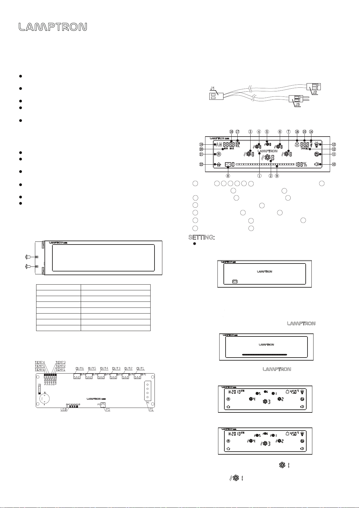
J1
J2
J3
PC switch wire interface mode: J1 connector P5; J2 connected PC
motherboard; J3 connect the PC button.
OPERATION:
LOGO;
1
channel switching area, where is the
current channel; slide to unlock arrow; slider area;
key tone switch; screensavers button; target temperature;
10
13
backlight adjustment button; temperature units;
15
temperature value; alarm switch; speed / voltage unit;
18
speed / voltage values; auto / manual switch; Min / Max;
computer switch button; Start boost mode
21
223 4 5 6
8
11
16 17
7
9
12
14
19
22
20
SETTING:
Icon in the user interface to connect the power cord, accessories and
load.
Powered display interface is shown below:
SPECIFICATIONS:
Dimension
LCD Dimension
Power Output
Control Channel
Color Available
DC Input
DC Output
Connectors
148.5mm * 42.5mm * 63mm
129mm * 32.5mm(wide screen)
Up to 15 watts per channel
6 Channels
Black Anodized/Silver
+ 12V(Standard “D” Connector)
0V - 12V DC
6pcs 3pin connectors
Installation location:
Please use the attached screws on the 5.25-inch bay on the computer
case (Phillips screwdriver needed and not included).
CONNECTIONS:
Instructions:
1. P1: Connect the power supply.
Tip: Be sure to use at least 18AWG wiring specifications.
2. Out1~Out6: channel 1 to channel 6 output interface for the
connected load fan. The six interfaces are standard with KF2510
3pin interfaces.
Tip: You can also smooth insertion KF2510 4pin connector.
3. TEMP1 ~ TEMP6: are respectively connected to the P1 ~ P6
corresponding to the temperature sensitive.
Tip: Automatic control of each output channel is carried out according
to the temperature of the corresponding sensor.
1.When the computer is not turned on;
Users can use the CM615 without the PC being on (requires computer
support turned off, USB interface 5V output remainining plugged in to
the motherboard).
Use: Touch the slider to the left slide to the right to display the slider
all the following figure, 12V is detected after flashing 3
times, and enters the main display interface.
2.Computer is in boot state;
Slide the slider from left to right, flashes 3 times, CM615
will then go to the main interface.
This figure shows the main display interface:
3.Once the client software is opened, it will show a successfully
connected icon below:
When the client application is not connected or
connected successfully,the fan icon is:
When the client application is connected successfully,
the fan icon is:
 Loading...