

Page 1
P
P
P
R
R
R
O
O
O
L
L
L
U
U
U
M
M
M
D
D
D
3
3
3
–
–
–
2
2
2
5
5
5
0
0
0
W
W
W
C
C
C
Y
Y
Y
M
M
M
c
c
c
o
o
o
l
l
l
o
o
o
u
u
u
r
r
r
c
c
c
h
h
h
a
a
a
n
n
n
g
g
g
e
e
e
r
r
r
USER’ S MANUAL release 1.0
This manual must be considered an integral part of the projector.
Page 2

1
BEFORE CONNECTING AND USING THE PROJECTOR, IT IS IMPORTANT TO READ CAREFULLY ALL THE
INSTRUCTIONS IN THIS MANUAL.
QUALIFIED PERSONNEL ONLY, IN COMPLIANCE WITH ALL THE SECURITY LAWS, CAN DO THE
INSTALLATION, THE MAINTENANCE AND THE UTILISATION OF THIS PROJECTOR.
BEFORE CONNECTING THE PROJECTOR, MAKE SURE THAT THE FREQUENCY AND THE VOLTAGE
VALUES ARE SUITABLE AS SPECIFIED ON THE PROJECTOR.
FOR ANY DOUBT, CONTACT YOUR SUPPLIER OR SEND AN E-MAIL TO:
tech@lamposrl.it
SOLID: Objects exceeding 12mm diameter
WATER: Non protected
Not suitable for direct mounting on normally flammable surfaces
Minimum distance from lighted objects (meters)
Rated maximum ambient temperature (indoor with ventilation)
Connection must be made to a power supply system fitted with efficient
earthing (EN60598-1 – Class I fixture)
Replace any cracked protective shield, dichroic filter or lens
Ignitor circuit lamp have very high voltage
Index
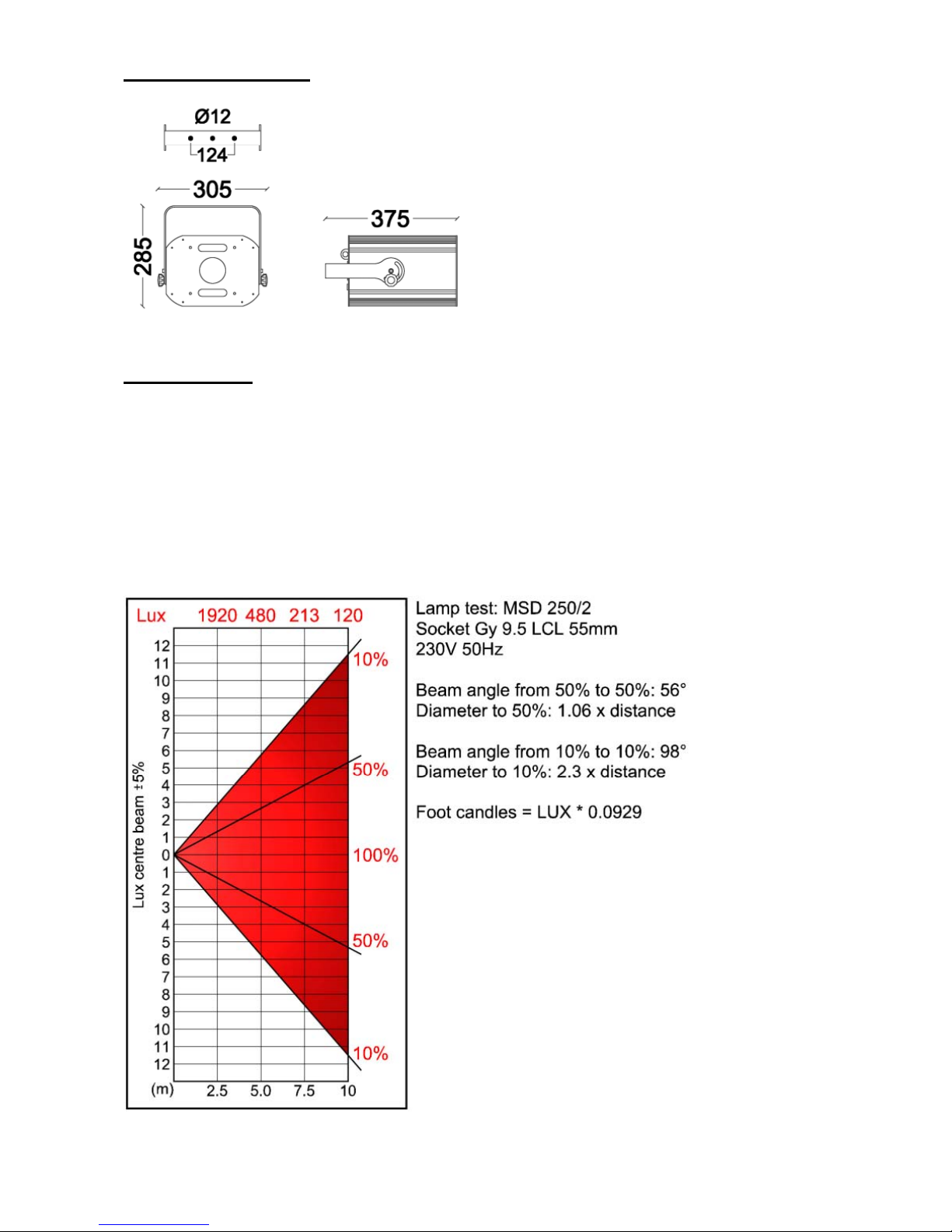
Dimensions and weight ---------------------------------------------------------------------------------- page 2
Technical data --------------------------------------------------------------------------------------------- page 2
Storage ------------------------------------------------------------------------------------------------------ page 3
Admissible environmental conditions ----------------------------------------------------------------- page 3
Power supply ---------------------------------------------------------------------------------------------- page 3
Example of connection ---------------------------------------------------------------------------------- page 4
DMX signal cable ----------------------------------------------------------------------------------------- page 4
DMX512 specifications ---------------------------------------------------------------------------------- page 6
User’s interface ------------------------------------------------------------------------------------------- page 8
Parameters of projector -------------------------------------------------------------------------------- page 9
Stand alone mode (Recordable dmx scenes) -------------------------------------------------------- page 10
Remote control of parameters ------------------------------------------------------------------------- page 11
Lamp replacement --------------------------------------------------------------------------------------- page 12
Lamp calibration ------------------------------------------------------------------------------------------ page 12
Page 3
2
Dimensions & weight
Weight: 10 Kg
Weight: 10 Kg
Technical data
- Aluminium body
- Silent small fan
- Brackets for adjustable fixing
- MSD 250W (base Gy9.5) lamp
- Magnetic ballast with power factor correction (1.8A max @ 230VAC with lamp ON)
- Colour changing system C.M.Y. (unlimited colours combination)
- Linear dimmer from 0 to 100%
- STROBE runs up to 10 flashes per second
- DMX controlled or 20 scenes recordable on projector
- The projector can work in all position
Page 4

3
Storage
The projector, in its original packing, must be kept in covered, dry areas with a temperature between –10°C and +50°C.
Attention, the projector will be damaged during the unpacking.
Admissible environmental conditions
The projector was engineered and produced to function in indoor areas with an air temperature ranging between 0° and 35°C
and with a humidity level between 30 and 90%.
When choosing the installation, please make sure that the device is not exposed to extreme heat or in small area.
Power supply
Disconnect mains power supply before any operations.
Connect the fixture to the mains. See the table and the drawing for the colours of the connection cable.
Do not power the projector with a dimmer circuit
Use the plug provided to connect the mains power.
When in doubt, consult a qualified electrician.
The projector can be fed with voltage between 210Vac and 240Vac (on the projector body is specified if 50 or 60 Hz). Overvoltage can damage the electronic parts of the projector or reduce the lamp life. It is advised to check the electric system before
installation.
When the projector is switched on, the starting current is proxy double from the nominal current. After one minute the lamp
has beam switched and the current absorbed goes down to 1.8A (230V).
The projector is complete grounded, it is necessary to connect the grounding system to the projector.
Protect the electric system with highly sensitive differential circuit breaker, 30mA.
The projector has a fuse, if a power failure should occur, that breaker the power supply, if damage change it with a fuse of the
same size.
Attention, the ignitor circuit inside the projector have a very high voltage, over 4.5KV.
Page 5

4
Example of connection
Example 1: The DMX signal is generated by a DMX controller, the signal cable goes in and out from each projector up to the
last one.
The projectors will execute the same scenes if the DMX addresses are the same (factory set is 1) or they can be driven one by
one if the DMX addresses are different from each other. (each projector uses 6 DMX channels):
Projector 1: DMX address 1 Projector 2: DMX address 7 Projector 3: DMX address 13
Example 2: The DMX signal is generated by a projector on stand alone mode (MASTER).
The projector MASTER will automatically execute scenes and it will drive the projector SLAVE of the same model.
In the two examples the projectors can be fed from different power sources, it is not necessary to switch on the projectors at the
same time.
If the DMX controller or the MASTER projector is not switched on, the projectors are on black-out (version with
dimmer/black-out) or they will project white light (version without dimmer/black-out).
DMX signal cable
Use only shielded and twisted cables with EIA485 (RS485) standards. The cable must be low capacity and an impedance
between 82 and 120 ohm.
It is preferable not to use audio cables.
We advise you to read the example of the following tables as a reference to use to correct cables.
Cables with 1 pair of wires Cables with 2 pairs of wires
Type Cod. AWG Impedance (ohm) Type Cod. AWG Impedance (ohm)
BELDEN 1162A 20 100 BELDEN 8102 24 100
BELDEN 8227 20 100 BELDEN 8162 24 100
BELDEN 89207 20 100 BELDEN 89696 22 100
ALPHA 9109 20 100 PROPLEX PC224P 22 110
ALPHA 9817 20 100 PROPLEX PC224T 22 110
ALPHA 9818 20 100
The wire size we recommended is 26 AWG or higher.
It is preferable:
- not to insert over 32 projectors each DMX chain
- not to use more than 150m of signal cable (with low quality cable)
- not to use more than 300m of signal cable (with good quality cable)
Page 6

5
Standard DMX controllers have only one signal out-put. If more than 32 projectors are used it is necessary to have a signal
SPLITTER, that will duplicate the signal in 2 or more lines.
If the signal cable is very long, it is necessary to install a signal AMPLIFIER on the DMX line (at least every 300m of good
quality cable), so that it will repeat the signal to the following projectors.
On the last projector of the signal chain it is necessary to insert a resistor (from 82 to 120 ohm) between positive and negative
terminal (+ and -).
Use MALE XLR 3 or 5 pin connector to connect the projectors to the DMX controller.
Use MALE / FEMALE 3 pin connectors to connect the projector to projector.
Solder on PIN 1 of the XLR connector the shield of the signal cable, on PIN 2 solder the negative (example: black wire of
cable) and on PIN 3 solder the positive (example: red or white wire of the cable).
The sequences and the colours has to be the same on each projector, do not change the sequences
Page 7

6
DMX512 specifications
The projector reads 6 consecutive DMX
DMX Ch. FUNCTION
channels starting from the set address. 1 Dimmer
2 Shutter/Strobe
The AUX channel always works as rainbow 3 Cyan
control channel and if REMOTE CONTROL 4 Magenta
is active (INDEX 5) also it works as remote 5 Yellow
control channel 6 Rainbow or Remote control
(ch. 1) Dimmer
Controls the intensity of the light beam from 0 to 100%. It also works during the Strobe function.
The value of this channel is ignored if the shutter channel is in the CLOSE position.
Function DMX Values Notes
Open 252..255
Proportional 4..251 Intensity Min ... Max
Close 0..3
(ch. 2) Shutter/Strobe
Selects blackout, channel open and strobe functions.
With the SHUT ON COLOUR function selected, the shutter closes during the colour change.
Function DMX Values Notes
Open 248..255
Close 240..247 Blackout (It has priority over the dimmer)
Strobe 29 232..239 Maximum rate (1 flash/sec)
Strobe 28 224..231
Strobe 27 216..223
Strobe 26 208..215
Strobe 25 200..207
Strobe 24 192..199
Strobe 23 184..191
Strobe 22 176..183
Strobe 21 168..175
Strobe 20 160..167
Strobe 19 152..159
Strobe 18 144..151
Strobe 17 136..143
Strobe 16 128..135
Strobe 15 120..127
Strobe 14 112..119
Strobe 13 104..111
Strobe 12 96..103
Strobe 11 88..95
Strobe 10 80..87
Strobe 9 72..79
Strobe 8 64..71
Strobe 7 56..63
Strobe 6 48..55
Strobe 5 40..47
Strobe 4 32..39
Strobe 3 24..31
Strobe 2 16..23
Strobe 1 8..15 Minimum rate
Close 0..7 Blackout (It has priority over the dimmer)
Page 8

7
(ch. 3) Cyan
Select the quantity of the Cyan colour proportionally to the value of the DMX channel.
“0” = NO COLOUR, “255” = FULL COLOUR
(ch. 4) Magenta
Select the quantity of the Magenta colour proportionally to the value of the DMX channel.
“0” = NO COLOUR, “255” = FULL COLOUR
(ch. 5) Yellow
Select the quantity of the Yellow colour proportionally to the value of the DMX channel.
“0” = NO COLOUR, “255” = FULL COLOUR
(ch. 6) Aux / Remote Control
If the REMOTE CONTROL is deactivate (default), the DMX channel 6 can enable the RAINBOW effect
DMX value from 0 to 54 = NO RAINBOW
DMX value from 55 to 255 = RAINBOW, from maximun speed to lower speed
The type of RAINBOW effect is definite from the parameter of index "RAINBOW TYPE" (R0, R1, R2, R3 and R4).
Graphic representations of the 5 patterns of RAINBOW effect. (x = time ; Y = % colours)
R0 R1
CYAN CYAN
MAGENTA MAGENTA
YELLOW YELLOW
DIMMER DIMMER
R2 R3 R4
CYAN CYAN
MAGENTA MAGENTA
YELLOW YELLOW
DIMMER DIMMER
The charts represent the temporal course of each channel interested to the effect (Cyan, Magenta, Yellow and Dimmer).
If possible select the % of colours of the rainbow, with the channels 3 – 4 – 5.
To obtain the completely images of the charts, the value of the DMX channels CYAN, MAGENTA, YELLOW must be = 255.
If the REMOTE CONTROL option is activated, the channel sends, via DMX, special codes to the projector. (page 11).
Page 9

8
User’s interface
Press and release the push-button MODE to access the different functions, as indicated by the three LED
Index (green led on): see the table in the next page for the meaning.
Use the + or - button to select the number of the Index.
Parameter (yellow led on): Use the + or - button to select the value of the Parameter which must be checked or modified.
To enable a modification, press the ENTER button; the display will flash twice as confirmation.
Fault (red led flashing): it is possible to access this mode only if a fault happens.
When the cause of the fault will be removed, the indication will be automatically removed too.
It is also possible to remove some fault indications, pressing the ENTER button.
Pressing the - button it is possible to see how many faults are enabled (in this case the red LED stops flashing),
pressing the + button, the system returns to the visualization of the current fault code.
Automatic return to the default visualization: if no buttons are pressed for more than 30 seconds, the system automatically
returns back to the default visualization: the DMX INDEX, if there aren't faults, or the current fault code.
Permanent visualization of a fault, when existing: when a fault happens, even if the Index or the Parameter mode
have been enabled, the red "LED" stay on.
Start-up codes: when the projector is switched on, the display visualises in a sequence, 2 codes that identify the software of
the main electronic board: first the Device Code
and second the Software Release.
Procedures of zero: while performing a start procedure, the display will show only one “0” on the middle digit.
Special function system: when the projector runs special functions, the 3-digit display flashes the same number.
222 - Remote control of the parameters
Faults
If the microprocessor finds a functional fault, it stores and shows that on the display.
CODE CAUSE EFFECT RESET
5 Absence of DMX signal The system waits for the signal Automatic
Page 10

9
Parameters
The parameters Boolean type (min=0, max=1) enable the controlled function when their value is = 1 and they unable it when
their value is = 0.
Index NAME EFFECT Min Default Max
0
DMX INDEX Sets the DMX address of the projector 1 1 507
2
SHUT ON
COLOUR
Closes the shutter before to change the colour, then re-open it 0 0 1
3
COLOUR
CONVERSION
Enables the halogen lamp simulation (Corrector Temperature
Orange):
No effect=0 ½ CTO = 1 CTO = 2
0 0 2
4
RAINBOW TYPE
Selects the pattern of the RAINBOW effect, which will be
enabled by the value of the DMX channel 6
0 0 4
5
REMOTE
CONTROL
Enables the possibility to remote control the parameter of the
projector via DMX
0 0 1
6
SYNCRO STROBE
SYNCRO STROBE = 0: does not guarantee the synchronism
of 2 or more projectors driven with the same DMX value
SYNCRO STROBE. = 1: is guarantee the synchronism
0 0 1
7
RESET COLOUR
Enables the manual reset of the colours actuators (the
parameter is automatically reset at the end of the procedure)
0 0 1
8
RESET
Enables the manual reset of the projector (the parameter is
automatically reset at the end of the procedure)
0 0 1
10
PROGRAM
EXECUTION
Enables the STAND ALONE function, sets the number of
STEPS to execute into the loop or enable the RESIDENT
PROGRAM
O = the projector receive the DMX signal
1 - 20 = select the steps of INSIDE MEMORY to execute
into the loop
0 0 21
11
PROGRAM STEP
Determines the current STEP of the inside memory to which
STEP SLOPE and STEP HOLD referred to
1 1 20
12
STEP SLOPE
Determines the time, in seconds, of the slope before the
current STEP
0 0 240
13
STEP HOLD
Determines the time, in seconds, of the current STEP
duration
0 1 240
14
LAMP LIFE
Shows the life time, in hours, of the lamp
Press the ENTER button to clear the counter
0 - 16.383
Page 11

10
Stand alone mode (recordable dmx scenes)
To start this execution, assign to Index n° 10 (PROGRAM EXECUTION) the value from 1 to 20.
It is possible to create an inside program that allows the projector to function on "stand-alone" mode, it is necessary to have a
DMX controller to record the scenes.
When the "stand-alone" function is enabled, the projector becomes a DMX generator. It will supply via DMX line, the values
corresponding to the inside program.
The inside program runs a loop up to 20 steps (PROGRAM STEP); each step contains: a DMX value of all the channels of the
projector, a time slope to achieve the new step (STEP SLOPE) and a hold time of the step (STEP HOLD).
WARNING: The projector in stand alone mode becomes a DMX generator, it is necessary to disconnect that projector
by DMX controller or by the other projector MASTER because generates conflict in the signal.
Storing of the steps
• Via the DMX controller, give to the projector the position and the image required
• Set the value of STEP SLOPE (Index 12) to assign the time (in seconds) of the transition from the previous
step to this new one
• Confirm with the ENTER button
• Set the value of STEP HOLD (Index 13) to assign the time (in seconds) of the hold time of this new step
• Confirm with the ENTER button
• Assign to the PROGRAM STEP parameter (Index 11) the number of the step you want memorize
• Push the ENTER button to store
Execution of the inside program
If the PROGRAM EXECUTION parameter (Index 10) contains "0", than the projector follows the command received from an
external DMX controller, otherwise, if it contains a value between "1" and "20", than the projector executes a loop of steps
from "1" to the number stored in the PROGRAM EXECUTION parameter.
Modification of the program during execution
If, during the execution of a program in "stand-alone" mode, you set a PROGRAM STEP value (Index 11) and then you push
the ENTER button, the program in execution will jump directly to the step required.
If, during the execution of a program in "stand-alone" mode, you set a STEP SLOPE value (Index 12) or a STEP HOLD value
(Index 13) and then you push the ENTER button, the corresponding parameter of the step in execution will be modified.
1 2 3 N
DMX
Time
Step 1
Step 2
Slope 1 Slope 2Hold 1 Hold 2
Page 12

11
Remote control of parameters
If the REMOTE ENABLE parameter (Index n°5) is equal to 1, then it is possible to modify or activate some functions of the
projector, via DMX. The activation of controls is based on a precise time sequence of the DMX channels values, if a step of
the sequence is wrong, the procedure will be deleted.
All the STEPS of the following table must be executed.
STEP DMX channels status Timing Action
1
CH1..CH5 = 0 4sec<time ------------------------------
2
CH1..CH5 = 0
CH6 = 255
2sec<time<4sec ------------------------------
3
CH1..CH5 = 0
CH6 = 0
2sec<time<4sec ------------------------------
4
CH1..CH5 = 0
CH6 = 255
2sec<time<4sec ------------------------------
5
CH1..CH5 = any
CH6 different from 0 and
from 255
2sec<time
The display flashes the number 222 to show the entrance in the
parameters remote control.
The coupling of the parameters and the DMX channels is as follow:
HP BLACKOUT Æ CH1
SHUT ON COLOUR Æ CH2
COLOUR CORRECTION Æ CH3
RAINBOW MODE Æ CH4
RESET Æ CH5
BOOLEAN PARAMETER
If the value of the DMX channel is minor than 9, the parameter will
remain the same.
If it is inclusive between 9 to 127, the parameter will be equal to 0.
If it is greater than 127, the parameter will be equal to 1.
NOT BOOLEAN PARAMETER
COLOUR CORRECTION:
If the value of the DMX channel is minor than 9, the parameter will
remain the same.
If it is inclusive between 9 to 90, the parameter will be equal to 0
If it is inclusive between 91 to 171, the parameter will be equal to 1.
If it is greater than 171, the parameter will be equal to 2.
RAINBOW TYPE:
If the value of the DMX channel is minor than 10, the parameter
will remain the same.
If it is inclusive between 10 to 59, the parameter will be 0.
If it is inclusive between 60 to 109, the parameter will be 1.
If it is inclusive between 110 to 159, the parameter will be 2.
If it is inclusive between 160 to 209, the parameter will be 3.
If it is greater than 209, the parameter will be equal to 4.
6
CH1..CH5 = any
CH6 = 0
------------
The display will return to the usual visualized condition, to signal
the exit from the remote control. The values of the DMX channels at
the moment of the exit from the remote control condition will
modify in a permanent way the parameters to which those are
coupled.
N.B. if the parameter RESET has been set at 1 will be executed a
global reset procedure of the projector.
Page 13

12
Lamp Replacement
1) Disconnect the projector from the main power supply
2) Unscrew the 4 screws “D” that hold the lamp holder
3) Remove the lamp holder
4) Remove the lamp, taking care to wear proper protective gloves
5) Insert a new lamp
6) Re-insert the lamp holder
7) Fix well the 4 screws that hold the lamp holder
DISCHARGE LAMPS CONTAIN SUBSTANCES THAT CAN
POLLUTE THE AMBIENCE. DISPOSE OF USING THE
APPROPRIATE REFUGES (TOXIC).
Lamp Calibration
Screwing / unscrewing the 3 regulation screws “A”, “B” and “C”,
you can lift or lower the lamp.
To bend the lamp, you have to operate on the “A” screw or on both “B” and “C” screws.
Screwing “A”, the lamp goes near to the “A” screw.
Screwing “B” and “C”, the lamp goes near to the “B” and “C”.
On request is available complete spare sparts list with wires diagrams (send e-mail plese)
The improper use of this projector, cancel the guarantee and our responsibility. All the information have been written and driven with
extreme care; however, we do not engage us any responsibility for contingent errors or omissions. We reserve the right to modify and/ or
improve our product as we retain necessary, without subsequent warning or notice. It is forbidden any complete or partial reproduction of
this handbook, if not expressly authorized.
 Loading...