

Page 1
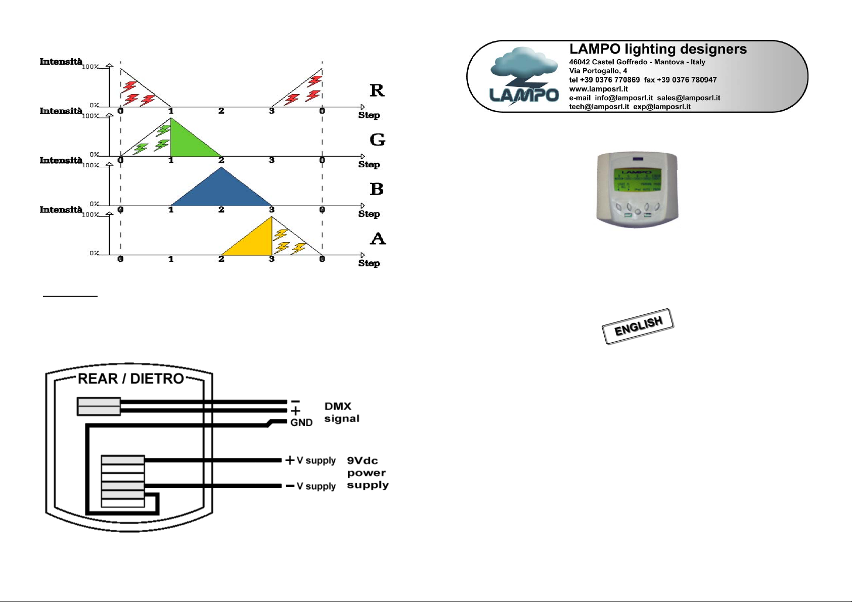
Here following the graphic of the colour mixing and the 4 steps strobe effect (pag. 7 ex.)
Connection
Disconnect mains before connection and maintenance.
Open the back lid to see the AMP 2 poles dmx connectors and the AMP 6 poles power supply
connectors.
8
L
E
D
C
O
N
T
R
O
L
L
E
L
L
E
E
D
D
C
O
N
T
R
O
C
O
N
T
R
O
L
L
L
L
E
E
R
R
R
D
M
X
d
e
d
i
c
a
t
e
d
L
E
D
c
o
n
t
r
o
l
l
e
r
D
D
M
M
X
X
d
e
d
i
c
a
t
e
d
L
E
D
c
o
n
t
r
d
e
d
i
c
a
t
e
d
L
E
D
c
o
n
o
t
r
o
l
l
e
r
l
l
e
r
USER’ S MANUAL release 1.0
This manual must be considered an integral part of the projector.
BEFORE CONNECTING AND USING THE CONTROLLER, IT IS IMPORTANT TO READ
CAREFULLY ALL THE INSTRUCTIONS IN THIS MANUAL.
QUALIFIED PERSONNEL ONLY, IN COMPLIANCE WITH ALL THE SECURITY LAWS,
CAN DO THE INSTALLATION AND THE MAINTENANCE OF THIS CONTROLLER.
BEFORE CONNECTING THE PROJECTOR, MAKE SURE THAT THE FREQUENCY AND
THE VOLTAGE VALUES.
FOR ANY DOUBT, CONTACT YOUR SUPPLIER OR SEND AN E-MAIL TO:
The improper use of this controller, cancel the guarantee and our responsibility. All the information have
been written and driven with extreme care; however, we do not engage us any responsibility for
contingent errors or omissions. We reserve the right to m odify and/ or improve our product as we retain
necessary, without subsequent warning or notice. It is forbidden any complete or partial reproduction of
tech@lamposrl.it
this handbook, if not expressly authorized.
Page 2

Index
Dimension ----------------------------------------------------------------------------- pag. 2
Technical data ------------------------------------------------------------------------ pag. 2
Functions description --------------------------------------------------------------- pag. 3
Manual mode ------------------------------------------------------------------------- pag. 3
Automatic mode ---------------------------------------------------------------------- pag. 4
Programming mode ----------------------------------------------------------------- pag. 5
Connections --------------------------------------------------------------------------- pag. 8
Dimension
Pic. 1 Holes for wall mounting
Technical data
- Plastic case
- Main supply 9Vdc, 300mA (included)
- Controls projector via DMX 512 signal
- Control up to 6 independent group of LED’s colour changer, (48 channels = 6 x 8ch)
- Manual mode or automatic mode
- Possibility to record up to 4 programs with 9 steps for each one
- Green light graphic display 128x64
- Multifunctional 5 digit keyboard
- Holes for wall mounting on the back (Pic. 1)
2
The display in zone 2 will show the labels from L1 to L6, with their values (from 0 to 255).
Each label represent one group of lights:
L1 = group 1 (dmx starting address 1)
L2 = group 2 (dmx starting address 9)
L3 = group 3 (dmx starting address 17)
L4 = group 4 (dmx starting address 25)
L5 = group 5 (dmx starting address 33)
L6 = group 6 (dmx starting address 41)
The display in zone 3 show the dmx values of R (Red), G (Green), B (Blue), A (Amber), and
ST (Strobe) of the group of lights used.
To modify the ongoing step assign a time different from 0 and with button C you can move
from one value to the other of the labels (from L1 to L6).
When you are on a label, use buttons A and B to modify the values and see what the projector
does if it is connect to the led controller or you can check on zone 3 the values.
After these steps, press button D to confirm and change the next label.
To assign the last step of a program, you have to put the seconds of following step to zero.
Example: to have a 3 steps program, you can edit the step 0, step 1 and step 2, then you must
put to zero the seconds of the step 3, after that push E button to save.
The led controller automatically mixes the steps, see the following example.
The led controller automatically mixes the steps of the program. It should not be possible to
assign mixing time and holding time of the colour in one step, but it is possible to assign the
holding time of this colour in two steps: step 1, choose the colour that will be mixed with the
previous colour (example 5 sec.); step 2, the same colour will remain for the set time
(example 10 sec).
7
Page 3

Programming mode
When using the programming mode, the display will be as follows:
Fig. 4
First thing to do is to choose one of the 4 program.
To select the programs press button A and B, one selected the desired program (between 0
and 3) pres button E.
To exit this mode without modifying anything press button D.
Each program (4) has maximum 9 scenes (called steps, from 0 to 8) each of variable timing.
Once a modification is done, you can see the projectors, connected to the led controller,
execute it immediately.
Once the program to execute has been chosen, the led controller will be as follows:
Fig. 5
The display in zone 1 will show:
PROG: number of the program chosen (from 0 to 3)
STEP: is the step that is executing (from 0 to 8)
SEC: is the time in second of executing the step (from o to 255)
6
Functions description
LED Controller is a dedicated console for led’s colour changers.
LED Controller is a DMX console, suitable for small applications and an easy to use but
professional controller for our led’s projectors.
LED Controller can control up to 6 groups of projectors via signal cable (DMX 512 signal).
One group is made by one or more projectors.
For each group there are 8 dmx channels, starting from channel 1.
Group 1 (from ch.1 to ch.8) Group 2 (from ch.9 to ch.17) Group 3 (from ch.18 to ch.25)
etc’….. up to ch. 48.
The dmx address (1
belong.
st
control channel) to the projectors depending to which group they
GROUP 1 GROUP 2 GROUP 3 GROUP 4 GROUP 5 GROUP 6
Ch. dmx 1 Ch. dmx 9 Ch. dmx 17 Ch. dmx 25 Ch. dmx 33 Ch. dmx 41
Manual mode
This mode will appear the first time the LED controller will be switched on.
With this mode it is possible to control intensity and the colour of the light output for each
group of projectors or for all the groups.
To set the projectors is necessary to change the parameters of the zone 1.
R, G, B, A e STROB (Zone1). The number down to letters (Zone 2) is the DMX values of the
colour channel, from 0 to 255.
Fig. 2
3
Page 4

The letters in zone 1 correspond to the led’s colours:
- R (Red leds)
- G (Green leds)
- B (Blue leds)
- A (Amber leds when used)
- STROB (frequency of the flashed of strobe effect)
The parameter in zone 2 is between 0 and 255 for each letter in zone 1
LED: 0 all led is off, 255 led on at the maximum power
Strobe: 0 the strobe effect is off, 255 the frequency rises to the maximum speed.
The symbols in zone 4 correspond to the function of the buttons A, B, D, E (Fig. 2).
Pressing the C button you can select the sections of the display.
The selected section will be light in hold characters, once selected the parameter, use button
A and B to change the value.
Zone 3: shows which group of projectors is used, see under the LIGHT N sign, you can
choose to control group 1 (select the value from 1 to 6) or to control all groups (select ALL).
To see how to assign a projector to one group see pag.2.
Pressing the D button (AUTO) you enter the automatic mode.
Pressing the E button (PROG) you enter the programming mode.
4
Automatic mode
The projectors connected to the led controller will execute the set program.
To choose a program press button A, in Zone 2 under “PROG:” is shown which of the 4
available programs is used.
In Zone 1 is shown the step and the time of execution.
The button B shows the performing mode used, single scene or continuous mode. The mode
used is shown on the display above button B.
Icona che rappresenta la modalità ripetuta.
Icona che rappresenta la modalità singola.
Continuous mode means that once the program is correctly set it repeats it self continuously
from beginning till the end.
Single scene mode means that once the program is finished, the projector will remain on the
last step of the scene.
If you switch off led controller when is functioning on automatic mode, the next time
switched on it will start the program that it was executing before being switched off.
Pressing the D button (AUTO) you enter the automatic mode.
Pressing the E button (PROG) you enter the programming mode.
Fig. 3
ATTENTION!!
5
 Loading...