

Page 1
DC1500 FLUORIDE
ACCEPTED
Fluoride Colorimeter Kit
Code 3243
Page 2

Page 3

CONTENTS
DC1500 Fluoride Kit
Kit Contents .......................................................................................... 5
Accessories .......................................................................................... 5
Test Method Specifications
Introduction .......................................................................................... 6
Application ............................................................................................ 6
Range ..................................................................................................... 6
Method .................................................................................................. 6
Handling & Preservation .................................................................... 6
Interferences ........................................................................................ 6
Analysis
Fluoride ................................................................................................. 7
Calibration
Standards ............................................................................................. 9
Calibration Procedure ......................................................................... 9
Set Up
Setting the Clock ...............................................................................13
Logging Data ......................................................................................14
Factory Setup .....................................................................................15
Setting Power Save ...........................................................................15
Setting Backlight Time .....................................................................16
Selecting A Language .......................................................................17
Looping Menus ................................................................................... 18
Computer Connection
Output ..................................................................................................19
Computer Connection ....................................................................... 19
Battery
Battery/AC Operation ........................................................................19
Battery Replacement ........................................................................ 20
Maintenance
Cleaning ..............................................................................................20
Repairs ................................................................................................20
Meter Disposal ...................................................................................21
General Operating Information
Overview .............................................................................................. 21
General Operating Information .......................................................21
The Keypad .........................................................................................22
The Display and Menus ..................................................................... 22
Tubes and Chambers.........................................................................24
Sample Dilution Techniques ............................................................25
Page 4

General information
Packaging and Delivery ....................................................................25
General Precautions .......................................................................... 25
Safety Precautions ............................................................................ 26
Limits of Liability ...............................................................................26
Specifications ....................................................................................27
CE .........................................................................................................28
IP67 ...................................................................................................... 28
Warranty .............................................................................................28
Register Your Meter...........................................................................28
Trouble Shooting Guide
Error Messages ..................................................................................29
Calibration ..........................................................................................29
Stray Light ..........................................................................................29
Troubleshooting Guide ......................................................................30
4
Page 5

DC1500 FLUORIDE KIT
Kit Contents
QUANTITY CONTENTS CODE
2 x 100 mL *Acid-Zirconly-SPADNS Reagent *3875-J
2 x 60 mL *Sodium Arsenite Solution *4128-H
1 Pipet, 0.5 mL, plastic 0353
1 Pipet, 1 mL Plastic 0354
1 Colorimeter Tubes, w/caps,set of 6 0290-6
1 Water Sample Collecting Bottle 0688
1 1500 Colorimeter for Fluoride 27926-FL
1 USB Wall Adapter 1721
1 USB Cable 1720
1 DC1500-FL Fluoride Colorimeter, Manual 3243-MN
1 DC1500-FL Fluoride Colorimeter,
Quick Start Guide
*WARNING: Reagents marked with an * are considered to be potential health
hazards.
www.lamotte.com.
reagent label, in the contents
that follows or precedes the four digit code number. For example if code is
4450WT-H, search 4450. To obtain a printed copy, contact LaMotte by e-mail,
phone or fax.
To view or print a Safety Data Sheet (SDS) for these reagents go to
Search the four digit reagent code number listed on the
list or in the test procedures. Omit any letter
3243-QG
Emergency information for all LaMotte reagents is available from Chem-Tel
(US, 1-800-255-3924) (International, call collect, 813-248-0585).
To order individual reagents or test kit components, use the specified code
number.
Accessories
DESCRIPTION CODE
Test Tubes, with Caps 0290-6
Replacement Chamber 3-0038
USB Cable 1720
USB Wall Adapter 1721
Car Charger 5-0132
5
Page 6

TEST METHODS SPECIFICATIONS
INTRODUCTION
Fluoride may occur naturally in some ground waters or it may be added
to public drinking water supplies to maintain a 1.0 mg/L concentration to
prevent dental cavities. At higher concentrations, fluoride may produce an
objectionable discoloration of tooth enamel called Fluorosis, though levels up
to 8 mg/L have not been found to be physiologically harmful.
APPLICATION
Drinking and surface waters; domestic and industrial waters.
RANGE
0.0 to 2.0 ppm Fluoride
METHOD
Colorimetric test based upon the reaction between Fluoride and zirconium
dye lake. The Fluoride reacts with the dye lake, dissociating a portion of it into
a colorless complex ion and dye. As the Fluoride concentration increases, the
color produced becomes progressively lighter.
HANDLING & PRESERVATION
Samples may be stored and refrigerated in plastic containers.
INTERFERENCES
The following substances produce a positive interference at the concentration
given:
Chloride (Cl-) 7000 mg/L
Phosphate (PO
Hexametaphosphate (NaPO3)
-3
) 16 mg/L
4
1 mg/L
6
The following substances produce a negative interference at the
concentration given:
Alkalinity (CaCO3) 5000 mg/L
Aluminum (Al+3) 0.1 mg/L
Iron (Fe+3) 10 mg/L
Sulfate (SO
-2
) 200 mg/L
4
Color and turbidity must be removed or compensated for in the procedure.
Temperature should be maintained within 5 degrees Celcius of room
temperature.
6
Page 7
ANALYSIS
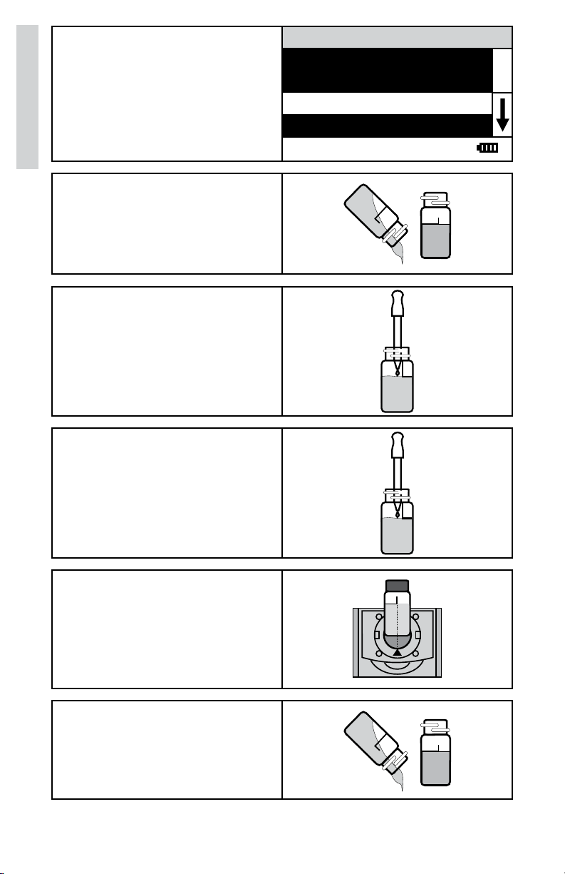
PROCEDURE
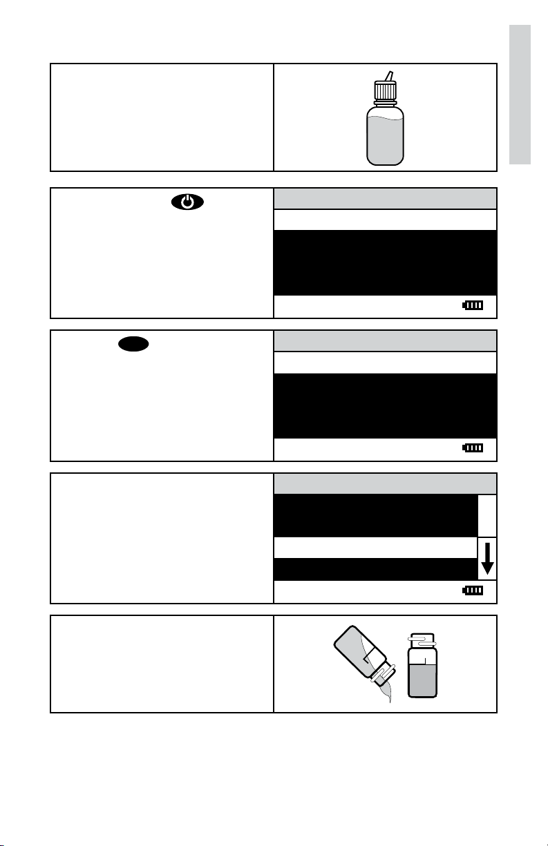
1. Fill the Water Sample Collecting
Bottle (0688) with sample
water.
Analysis
2. Press and hold until
colorimeter turns on.
3. Press
ENTER
to select Testing
Menu.
4. Scroll to and select 045 Fluoride
from menu.
Main Menu
Testing Menu
Editing Menu
12:00:00 001/500
All Tests
045 Fluoride
12:00:00 001/500
045 Fluoride
Scan Blank
Scan Sample
12:00:00 001/500
5. This test requires a reagent
blank. Rinse a clean colorimeter
tube (0290) with clear, colorless,
Fluoride free water.
10 mL line
with clear, colorless,
Fill to the
Fluoride free water.
7
Page 8
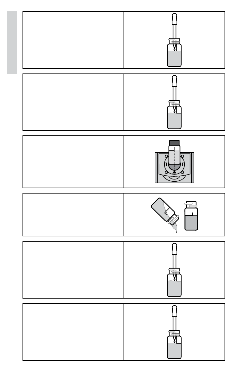
6. Use the 0.5 mL pipet (0353) to
add 0.5 mL of *Sodium Arsenite
Solution (4128). Cap and mix.
Analysis
7. Use the 1.0 mL pipet (0354)
to add 2 measures of *AcidZirconyl SPADNS Reagent
(3875). Cap and mix thoroughly.
(This is the reagent blank.) Dry
the tube with a lint-free cloth.
8. Insert tube into chamber, close
lid and select Scan Blank.
9. Rinse a clean colorimeter tube
(0290) with sample
water. Fill
to the 10 mL line with sample
water.
10. Use the 0.5 mL pipet (0353) to
add 0.5 mL of *Sodium Arsenite
Solution (4128). Cap and mix.
11. Use the 1.0 mL pipet (0354)
to add 2 measures of *AcidZirconyl SPADNS Reagent
(3875). Cap and mix thoroughly.
(This is the reagent blank.) Dry
the tube with a lint-free cloth.
8
Page 9
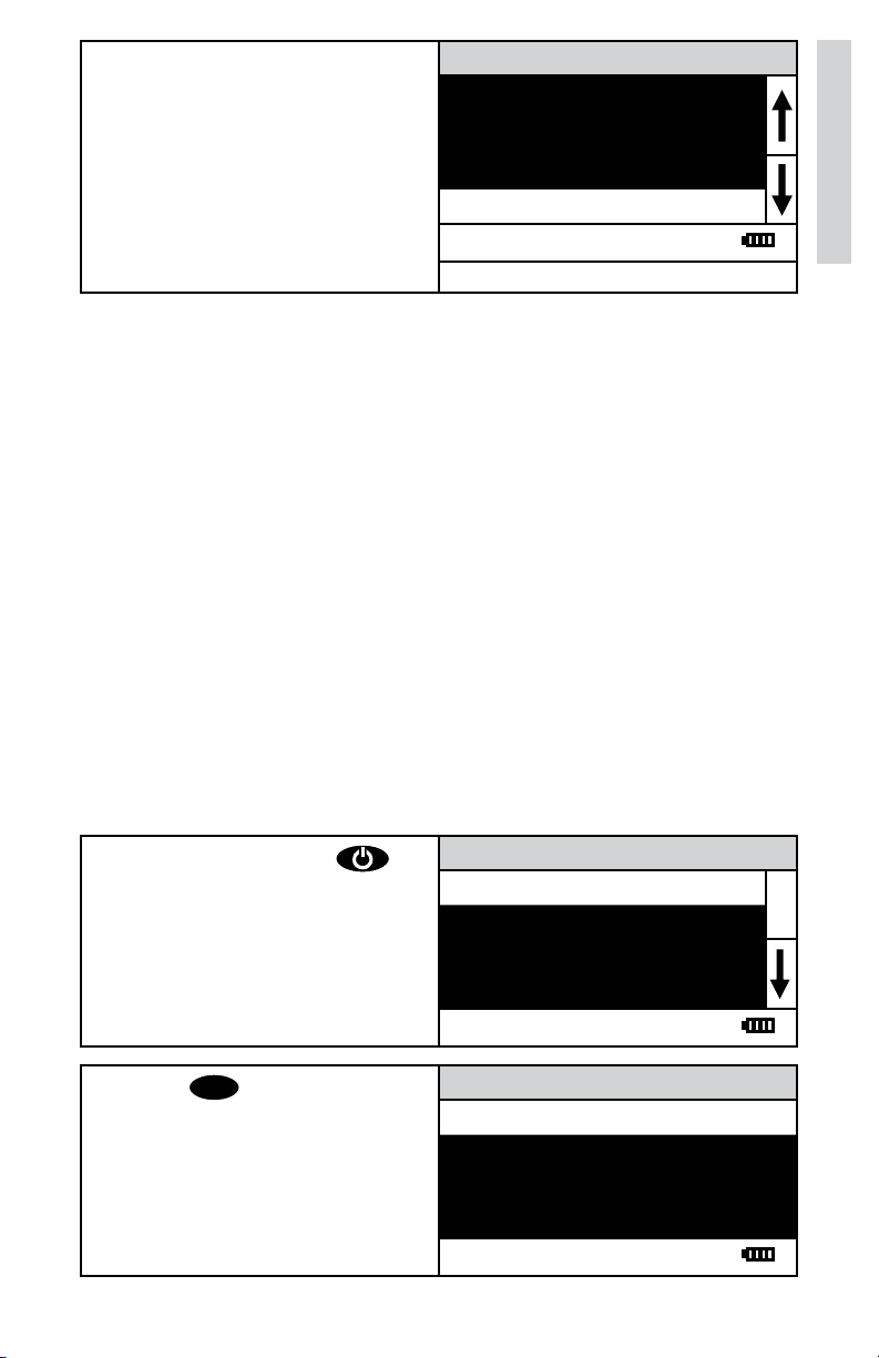
12. Insert tube into chamber. Close
lid. Select Scan Sample. Record
result as Fluoride.
NOTE: Zeroing the meter with the sample water will result in an error. Meter
must be zeroed with a reagent blank.
NOTE: The meter will remember the last scanned blank reading. It is not
necessary to scan a blank each time the test is performed. To use the
previous blank reading, instead of scanning a new one, scroll to Scan Sample
and proceed. For the most accurate results, the meter should be blanked
before each test and the same tube should be used for the blank and the
reacted sample.
0.9 ppm
Scan BLank
Scan Sample
12:00:00 001/500
045 Fluoride
CALIBRATION
STANDARDS
The meter should be calibrated with fluoride standards. The calibration should
be done with a distilled or deionized water blank and one fluoride standard of
known concentration. The concentration of the calibration standard should be
similar to the expected concentration of the sample that will be tested.
Calibration
CALIBRATION PROCEDURE
1. Press and briefly hold to
turn the meter on. The LaMotte
logo screen will appear for about
3 seconds and the Main Menu
will appear.
Menu.
ENTER
to select Testing
2. Press
Main Menu
Testing Menu
Editing Menu
12:00:00 001/500
All Tests
045 Fluoride
12:00:00 001/500
9
Page 10
3. Scroll to and select 045 Fluoride
from menu.
Calibration
4. This test requires a reagent
blank. Rinse a clean colorimeter
tube (0290) with clear, colorless,
Fluoride free water.
10 mL line
with clear, colorless,
Fill to the
Fluoride free water.
5. Use the 0.5 mL pipet (0353) to
add 0.5 mL of *Sodium Arsenite
Solution (4128). Cap and mix.
6. Use the 1.0 mL pipet (0354)
to add 2 measures of *AcidZirconyl SPADNS Reagent
(3875). Cap and mix thoroughly.
(This is the reagent blank.) Dry
the tube with a lint-free cloth.
045 Fluoride
Scan Blank
Scan Sample
12:00:00 001/500
7. Insert tube into chamber, close
lid and select Scan Blank.
8. Rinse a clean colorimeter tube
(0290) with sample
water. Fill
to the 10 mL line with sample
water.
10
Page 11

9. Use the 0.5 mL pipet (0353) to
add 0.5 mL of *Sodium Arsenite
Solution (4128). Cap and mix.
10. Use the 1.0 mL pipet (0354)
to add 2 measures of *AcidZirconyl SPADNS Reagent
(3875). Cap and mix thoroughly.
(This is the reagent blank.) Dry
the tube with a lint-free cloth.
Calibration
11. Insert tube into chamber. Close
lid. Select Scan Sample.
12. Press to scroll to
Calibrate.
13. Press
ENTER
to select Calibrate.
A reverse font (light background
with dark characters) will appear
to indicate that the reading can
be adjusted.
045 Fluoride
0.9 ppm
Scan BLank
Scan Sample
12:00:00 001/500
045 Fluoride
0.9 ppm
%T/Abs
Calibrate
12:00:00 001/500
045 Fluoride
0.9 ppm
∧, ∨=Edit, ENTER=Save
∧ +ENTER=Default
12:00:00 001/500
11
Page 12

14. Press or to
adjust the value shown to the
concentration of the prepared
standard, 1.0 in this example.
NOTE: A maximum adjustment
Calibration
of 25% is possible.
045 Fluoride
1.0 ppm
∧, ∨=Edit, ENTER=Save
∧ +ENTER=Default
12:00:00 001/500
15. Press
ENTER
to save the value.
To leave the Calibration
procedure without saving the
adjustment, press
Press and
time to return to the default
value.
The calibration has now been
standardized and can be used
for testing. Scroll to Scan Blank
and begin testing.
EXIT
ENTER
.
at any
045 Fluoride
1.0 ppm
%T/Abs
Calibrate
12:00:00 001/500
12
Page 13

SET UP
SETTING THE CLOCK
Setting the clock allows the correct time and date stamp to be stored with
each reading in the data logger.
1. From the Editing Menu, press
or to scroll to Set
Clock.
2. Press
ENTER
to select Set Clock.
The year is displayed. Press
or to scroll to the
appropriate character. Press
ENTER
to select the character.
The month, day, hour, format
hour, minute, second, AM/PM
will be dislpayed. Repeat for
each.
3. Press
ENTER
to select the final
character. The time and date
will be saved and the meter will
return to the Editing Menu.
Editing Menu
Set Clock
Logging
Factory Setup
Set Power Save
12:00:00 001/500
Set Time
Year: 2000
12:00:00 001/500
Editing Menu
Set Clock
Logging
Factory Setup
Set Power Save
12:00:00 001/500
13
Page 14

LOGGING DATA
The default setting for the data logger is enabled. The meter will log the last
500 data points. The counter in the center bottom of the display will show how
many data points have been logged. The display will show 500+ when the data
logger has exceeded 500 points and the data points are being overwritten.
1. From the Editing Menu, press
or to scroll to
Logging.
2. Press
ENTER
to select Logging.
3. Press or to scroll to
desired function.
Editing Menu
Set Clock
Logging
Factory Setup
Set Power Save
12:00:00 001/500
Logging
Display Test Log
Logging Enabled
Logging Disabled
Erase Log
12:00:00 001/500
Logging
Display Test Log
Logging Enabled
Logging Disabled
Erase Log
12:00:00 001/500
4. Press
ENTER
. The screen will
display Storing... for about 1
second and return to the Editing
Menu.
Editing Menu
Set Clock
Logging
Factory Setup
Set Power Save
12:00:00 001/500
14
Page 15

FACTORY SETUP
The Factory Setup menu is used in manufacturing of the colorimeter. This
menu is not for use by the operator in the field.
SETTING POWER SAVE
The power saving Auto Shutoff feature will turn the meter off when a button
has not been pushed for a set amount of time. The default setting is disabled.
To change the setting:
1. From the Editing Menu, press
or to scroll to Set
Power Save.
2. Press
ENTER
to select Set Power
Save.
3. Press or to scroll to
desired function.
Editing Menu
Set Clock
Logging
Factory Setup
Set Power Save
12:00:00 001/500
Set Power Save
Disable
5 Minutes
15 Minutes
30 Minutes
12:00:00 001/500
Set Power Save
Disable
5 Minutes
15 Minutes
30 Minutes
12:00:00 001/500
4. Press
ENTER
. The screen will
display Storing.... for about 1
second and the meter will retun
to the Editing Menu.
Editing Menu
Set Clock
Logging
Factory Setup
Set Power Save
12:00:00 001/500
15
Page 16

SETTING THE BACKLIGHT TIME
The backlight illuminates the display for enhanced viewing. The default setting
is 10 seconds. If Button Control is chosen the backlight button on the key pad
will act as an on/off switch and the backlight will remain on or off when the
meter is being used. When one of the other settings – 10, 20 or 30 seconds –
is chosen, the display will be illuminated for the specified amount of time after
any button is pressed.
NOTE: The backlight feature uses a significant amount of power. The longer
the backlight is on, the more frequently the battery will have to be charged if
the USB/Wall Adapter is not being used.
1. From the Editing Menu, press
or to scroll to
Backlight Time.
2. Press
ENTER
to select Set
Backlight Time.
3. Press or to scroll to
desired option.
Editing Menu
Logging
Factory Setup
Set Power Save
Set Backlight Time
12:00:00 001/500
Set Backlight Time
Button Control
10 seconds
20 seconds
30 seconds
12:00:00 001/500
Set Backlight Time
Button Control
10 seconds
20 seconds
30 seconds
12:00:00 001/500
4. Press
ENTER
. The screen will
display Storing... for about 1
second and the meter will return
to the Editing Menu.
Editing Menu
Logging
Factory Setup
Set Power Save
Set Backlight Time
12:00:00 001/500
16
Page 17

SELECTING A LANGUAGE
There are seven languages available: English, Spanish, French,
Portuguese, Italian, Chinese, and Japanese.
1. From the Editing Menu, press
or to scroll to
Select Language.
2. Press
ENTER
to select Select
Language.
3. Press or to scroll to
desired language.
Editing Menu
Factory Setup
Set Power Save
Set Backlight Time
Select Language
12:00:00 001/500
Select Language
English
Spanish
French
Portugese
12:00:00 001/500
Select Language
English
Spanish
French
Portugese
12:00:00 001/500
4. Press
ENTER
. The screen will
display Storing... for about 1
second and the meter will return
to the Editing Menu.
Set Power Save
Set Backlight Time
Editing Menu
Bluetooth Menu
Select Language
12:00:00 001/500
NOTE: If meter unintentionally switches to another language, use the
procedure above to reset the meter to the desired language. For example, to
reset the meter to English:
Turn meter on.
1. Press
2. Press
3. Press
one time. Press
five times. Press
ENTER
.
ENTER
ENTER
.
.
17
Page 18

LOOPING MENUS
Long menus, such as the Tsting Menu, incorporate a looping feature which
allows the user to quickly reach the last choice in the menu from the first
choice. In a looping menu the last choices in the menu are above the first
choice and scrolling upward moves through the menu in reverse order.
Scrolling downward moves through the menu from first choice to last but
the menu starts over following the last choice. So all menu choices can be
reached by scrolling in either direction. The diagrams below demonstrate a
looping menu.
AND SO ON AND SO ON AND SO ON
: : : : : : : : :
: : : : : : : : :
THIRD TO LAST LAST CHOICE LAST CHOICE
SECOND TO LAST AND SO ON AND SO ON
LAST CHOICE : : : : : :
TESTING MENU TESTING MENU TESTING MENU
FIRST CHOICE
SECOND CHOICE THIRD TO LAST THIRD TO LAST
THIRD CHOICE
ANOTHER LAST CHOICE LAST CHOICE
12:00:00 001/500 12:00:00 001/500 12:00:00 001/500
AND ANOTHER FIRST CHOICE FIRST CHOICE
AND SO ON SECOND CHOICE SECOND CHOICE
: : : THIRD CHOICE THIRD CHOICE
: : : ANOTHER ANOTHER
LAST CHOICE AND ANOTHER AND ANOTHER
: : : : : :
SECOND TO LAST SECOND TO LAST
The feature called Looping Menu can be turned on and off in the Editing
Menu. The default setting is ON.
18
Page 19

COMPUTER CONNECTION
OUTPUT
USB
COMPUTER CONNECTION
USB Type A, USB mini B, Order Cable Code 1720.
BATTERY
BATTERY/AC OPERATION
The colorimeter may be operated on battery power, using a USB wall adapter
or USB computer connection. If using the meter as a bench top unit, use the
wall adapter if possible to extend the battery life. The meter will remain on
when the USB adapter is used.
To charge the battery with the wall adapter, plug the smaller end of the USB
cable (USB mini B connector) into the meter and the larger end of the USB
cable (USB Type A connector) into the wall adapter. Plug the wall adapter into
an AC outlet. Reinsert the USB port plug after charging.
To charge the battery from a computer, plug the smaller end of the USB cable
(USB mini B connector) into the meter and the larger end of the USB cable
(USB Type A connector) into a USB port on a computer.
The battery icon will show no bars and flash when the unit first turns on. Then
the indicator will indicate the battery status by showing 0, 1, 2, 3 or 4 bars.
It will take 5 hours to fully charge a low battery. The battery icon will flash
when the battery is charging. The battery icon will show four bars and stop
flashing when it is fully charged. The charging circuit will automatically switch
to a float charge when the battery is fully charged. The charger may remain
connected. Some computers will NOT supply power to their USB ports during
standby operation. The wall adapter will charge the unit continuously.
The battery icon will show no bars and continuously flash if the battery is
getting low but the unit will still operate normally. A “Low Battery” message on
the status bar of the display will replace the time when the battery voltage is
too low for proper operation and accuracy may be degraded. A “Shutdown Low
Batt” message on the display will appear for a few seconds before the power
is switched off when the battery is too low to operate the unit.
To extend the battery life:
• Shut down the unit with the power switch when not taking
measurements or use the power save option to have the unit
automatically turn off after 5 minutes.
• Store the unit in a cool dry place.
• Fully charge the battery before storing the unit for extended periods
of time.
• Limit backlight use. The unit consumes 3X normal power with the
backlight on. Set the backlight time option to 10 seconds, or select
“Button Control” and keep the backlight off.
19
Page 20

BATTERY REPLACEMENT
The lithium ion battery used in this unit should last for many years with
normal use. When it no longer powers the unit long enough to meet testing
requirements it will need to be replaced. Lithium ion batteries that are
properly charged and stored do not usually lose all capacity; they just have
less capacity after hundreds of charge cycles. This unit uses a custom battery
assembly that is only available from LaMotte Company. Battery replacement
must be performed at a LaMotte authorized repair facility. The water resistant
housing of this meter should not be opened by the user. Contact LaMotte
Company by phone (1-800-344-3100) or email (tech@lamotte.com) for a
return authorization number.
MAINTENANCE
CLEANING
Clean the exterior housing with a damp, lint-free cloth. Do not allow water
to enter the light chamber or any other parts of the meter. To clean the
light chamber and optics area, point a can of compressed air into the light
chamber and blow the pressurized air into the light chamber. Use a cotton
swab dampened with Windex® window cleaner to gently swab the interior of
the chamber. Do not use alcohol; it will leave a thin residue over the optics
when dry.
REPAIRS
Should it be necessary to return the meter for repair or servicing, pack the
meter carefully in a suitable container with adequate packing material. A
return authorization number must be obtained from LaMotte Company by
calling 800-344-3100 (US only) or 410-778-3100, faxing 410-778-6394,
or emailing tech@lamotte.com. Often a problem can be resolved over the
phone or by email. If a return of the meter is necessary, attach a letter with
the return authorization number, meter serial number, a brief description of
problem and contact information including phone and FAX numbers to the
shipping carton. This information will enable the service department to make
the required repairs more efficiently.
20
Page 21

METER DISPOSAL
Waste Electrical and Electronic Equipment (WEEE)
Natural resources were used in the production of this equipment. This
equipment may contain materials that are hazardous to health and the
environment. To avoid harm to the environment and natural resources, the
use of appropriate take-back systems is recommended. The crossed out
wheeled bin symbol on the meter encourages the use of these systems when
disposing of this equipment.
Take-back systems will allow the materials to be reused or recycled in a
way that will not harm the environment. For more information on approved
collection, reuse, and recycling systems contact local or regional waste
administration or recycling services.
GENERAL OPERATING INFORMATION
OVERVIEW
The meter is a portable, microprocessor controlled, direct reading colorimeter.
It has a graphical liquid crystal display and 6 button keypad. These allow the
user to select options from the menu driven software, to directly read test
results or to review stored results of previous tests in the data logger. The
menus can be displayed in seven different languages.
The LaMotte tests are precalibrated for LaMotte reagent systems.
The colorimeter displays the result of these tests directly in units of
concentration.
The optics feature a colored LED. The LED has a corresponding silicon
photoiode with an integrated interference filter. The interference filter selects
a narrow band of light from the corresponding LED for the colorimetric
measurements.
A USB wall adapter, USB computer connection or lithium battery powers the
colorimeter.
GENERAL OPERATING INFORMATION
The operation of the colorimeter is controlled by the menu driven software
and user interface. A menu is a list of choices. This allows a selection of
various tasks for the colorieter to perform, such as scan blank and scan
sample. The keypad is used to make menu selections that are viewed on the
display.
21
Page 22

THE KEYPAD
The keypad has 6 buttons which are used to perform specific tasks.
This button will scroll up through a list of menu selections.
ENTER
The button is used to select choices in a menu viewed on the
display.
This button controls the backlight on the display.
This button will scroll down through a list of menu selections.
EXIT
This button exits to the previous menu.
This button turns the meter on or off.
ENTER
EX I T
THE DISPLAY AND MENUS
The display allows menu selections to be viewed and selected. These
selections instruct the colorimeter to perform specific tasks. The menus are
viewed in the display using two general formats that are followed from one
menu to the next. Each menu is a list of choices or selections.
The display has a header line at the top and a footer line at the bottom. The
header displays the title of the current menu. The footer line displays the
time and the date, the data logger status and the battery status. The menu
selection window is in the middle of the display between the header and the
footer.
The menu selection window displays information in two general formats. In
the first format only menu selections are displayed. Up to 4 lines of menu
selections may be displayed. If more selections are available they can be
viewed by pressing the arrow buttons to scroll the other menu
selections into the menu selection window. Think of the menu selections as
a vertical list in the display that moves up or down each time an arrow button
is pressed. Some menus in the colorimeter are looping menus.
The top and bottom menu choices are connected in a loop. Scrolling down
past the bottom of the menu will lead to the top of the menu. Scrolling up
past the top of the menu will lead to the bottom of the menu.
22
Page 23

Header Menu Title
Main Window Selection First Choice
Second Choice
Third Choice
Another
Footer
12:00:00 001/500 P
And Another
And So On
A light bar will indicate the menu choice. As the menu is scrolled through, the
light bar will highlight different menu choices. Pressing the
select the menu choice that is indicated by the light bar.
In the second format the menu choice window takes advantage of the
graphical capabilities of the display. Large format graphic information, such
as test results or error messages or the LaMotte logo is displayed. The top
two lines of the display are used to display information in a large, easy to read
format. The menus work in the same way as previously described but two lines
of the menu are visible at the bottom of the display.
Header Menu Title
Message or Result Window
ENTER
button will
Result or
Message
Another
Main Window Selection And Another
Footer
As described previously, the
current menu and a return to the previous menu. This allows a rapid exit from
an inner menu to the main menu by repeatedly pushing the
Pushing at any time will turn the colorimeter off.
EXIT
12:00:00 001/500
And So On
Last Choice
button allows an exit or escape from the
EXIT
button.
23
Page 24

The display may show the following messages:
Battery Status
More choices are available and can be viewed by scrolling
up and/or down through the display.
Header Identifies the current menu and information on units and
reagent systems if applicable.
Footer In the data logging mode the number of the data point
is displayed and the total number of data points in the
memory will be shown. The footer also shows current time
and battery status
TUBES AND CHAMBERS
The colorimeter uses one type of tube (Code 0290) for all test factors.
The handling of the tubes is of utmost importance. Tubes must be clean and
free from lint, fingerprints, dried spills and significant scratches, especially
the central zone between the bottom and the sample line.
Scratches, fingerprints and water droplets on the tube can cause stray light
interference leading to inaccurate results. Tubes that have been scratched in
the light zone through excessive use should be discarded and replaced with
new ones.
Tubes should always be washed on the inside and outside with mild detergent
prior to use to remove dirt or fingerprints. The tubes should be allowed to airdry in an inverted position to prevent dust from entering the tubes. Dry tubes
should be stored with the caps on to prevent contamination.
After a tube has been filled and capped, it should be held by the cap and the
outside surface should be wiped with a clean, lint-free absorbent cloth until it
is dry and smudge-free. Handling the tube only by the cap will avoid problems
from fingerprints. Always set the clean tube aside on a clean surface that will
not contaminate the tube. It is imperative that the tubes and light chamber be
clean and dry. The outside of the tubes should be dried with a clean, lint-free
cloth or disposable wipe before they are placed in the meter chamber.
Tubes should be emptied and cleaned as soon as possible after reading a
sample to prevent deposition of particulates on the inside of the tubes.
Variability in the geometry of the glassware and technique is the predominate
cause of variability in results. Slight variations in wall thickness and the
diameter of the tubes may lead to slight variations in the test results. To
eliminate this error the tubes should be placed in the chamber with the same
orientation each time.
Chambers which have been scratched through excessive use should be
discarded and replaced with a new one.
24
Page 25

SAMPLE DILUTION TECHNIQUES
If a test result is out of the range of the meter, it must be diluted. The test
should then be repeated on the diluted sample. The following table gives quick
reference guidelines for dilutions of various proportions.
Amount of Sample Deionized Water to Bring
Final Volume to 10 mL
10 mL 0 mL 1
5 mL 5 mL 2
2.5 mL 7.5 mL 4
1 mL 9 mL 10
0.5 mL 9.5 mL 20
All dilutions are based on a final volume of 10 mL, so several dilutions will
require small volumes of the water sample. Graduated pipets should be
used for all dilutions. If volumetric glassware is not available, dilutions can
be made with the colorimeter tube. Fill the tube to the 10 mL line with the
sample and then transfer it to another container. Add 10 mL volumes of
deionized water to the container and mix. Transfer 10 mL of the diluted
sample to the colorimeter tube and follow the test procedure. Repeat the
dilution and testing procedures until the result falls within the range of the
calibration. Multiply the test result by the dilution factor. For example, if 10 mL
of the sample water is diluted with three 10 mL volumes of deionized water,
the dilution factor is four. The test result of the diluted sample should be
multiplied by four.
Multiplication Factor
GENERAL INFORMATION
PACKAGING AND DELIVERY
Experienced packaging personnel at LaMotte Company assure adequate
protection against normal hazards encountered in transportation of
shipments.
After the product leaves LaMotte Company, all responsibility for safe delivery
is assured by the transportation company. Damage claims must be filed
immediately with the transportation company to receive compensation for
damaged goods.
GENERAL PRECAUTIONS
READ THE INSTRUCTION MANUAL BEFORE ATTEMPTING TO SET UP OR
OPERATE THE METER. Failure to do so could result in personal injury or
damage to the meter. The meter should not be used or stored in a wet or
corrosive environment. Care should be taken to prevent water from wet tubes
from entering the meter chamber.
NEVER PUT WET TUBES IN THE METER.
25
Page 26

SAFETY PRECAUTIONS
Read the labels on all LaMotte reagent containers prior to use. Some
containers include precautionary notices and first aid information. Certain
reagents are considered hazardous substances and are designated with
a * in the instruction manual. Safety Data Sheets (SDS) can be found at
www.lamotte.com. Read the SDS before using these reagents. Additional
emergency information for all LaMotte reagents is available 24 hours a day
from the National Poison Control Center 1-800-222-1222 or by contacting
the 24 hour emergency line for ChemTel 1-800-255-3924 (USA, Canada,
Puerto Rico); locations outside the North American Continent 813-2480585 (call collect). Be prepared to supply the name and four-digit LaMotte
code number found on the container label or at the top of the SDS or in
the contents list of the procedure. LaMotte reagents are registered with a
computerized poison control information system available to all local poison
control centers.
Keep equipment and reagent chemicals out of the reach of young children.
Ensure that the protection provided by this equipment is not impaired. Do not
intall or use this equipment in a manner that is not indicated in this manual.
LIMITS OF LIABILITY
Under no circumstances shall LaMotte Company be liable for loss of life,
property, profits, or other damages incurred through the use or misuse of its
products.
26
Page 27

SPECIFICATIONS & RANGES
INSTRUMENT TYPE: Colorimeter
Readout 160 x 100 backlit LCD, 20 x 6 line graphical
display
Wavelengths 568 nm
Wavelength Accuracy ±2% FS
Readable Resolution Determined by reagent system
Wavelength Bandwidth 10 nm typical
Photometric Range –2 to +2 AU
Photometric Precision ± 0.001 AU at 1.0 AU
Photometric Accuracy ±0.005 AU at 1.0 AU
Sample Chamber Accepts 25 mm diameter flat-bottomed test
tubes
Light Sources 1 LEDs
Detectors 1 silicon photodiode
Modes Pre-programmed tests, absorbance, %T
Pre-Programmed Tests YES, with automatic wavelength selection
Languages English, Spanish, French, Portuguese, Italian,
Chinese, Japanese
Temperature Operation: 0-50 °C; Storage: -40-60 °C
Operation Humidity
Range
USB Port Mini B
Power Requirements USB wall adapter, USB computer connection or
Battery Charge Life: Approximately 380 tests with
Electrical Rating Rated voltage (5V), Rated power of input current
Data Logger 500 test results
Waterproof IP67 with USB port plug in place
Dimensions (LxWxH) 3.5 x 7.5 x 2.5 inches, 8.84 x 19.05 x 6.35 cm
0-90 % RH, non-condensing
lithium ion rechargeable battery
backlight on to 1000 tests with backlight off.
Battery Life: Approximately 500 charges.
(1.0A) at mini-USB input port
Weight 13 oz, 362 g (meter only)
27
Page 28

CE COMPLIANCE
The colorimeter has been independently tested and has earned the European
CE Mark of compliance for electromagnetic compatibility and safety. To view
certificates of compliance, go to the LaMotte website at www.lamotte.com.
IP67 Certification
The meets IP67 standards for protection against dust and immersion only
when the USB port plug is in place. Documentation is available at www.
lamotte.com.
WARRANTY
LaMotte Company warrants this instrument to be free of defects in parts
and workmanship for 2 years from the date of shipment. If it should become
necessary to return the instrument for service during or beyond the warranty
period, contact our Technical Service Department at 1-800-344-3100 for a
return authorization number or visit www.lamotte.com for troubleshooting
help. The sender is responsible for shipping charges, freight, insurance and
proper packaging to prevent damage in transit. This warranty does not
apply to defects resulting from action of the user such as misuse, improper
wiring, operation outside of specification, improper maintenance or repair,
or unauthorized modification. LaMotte Company specifically disclaims any
implied warranties or merchantability or fitness for a specific purpose and
will not be liable for any direct, indirect, incidental or consequential damages.
LaMotte Company’s total liability is limited to repair or replacement of the
product. The warranty set forth above is inclusive and no other warranty,
whether written or oral, is expressed or implied.
REGISTER YOUR METER
To register your meter with the LaMotte Service Department, go to
www.lamotte.com and choose SUPPORT on the top navigation bar.
28
Page 29

TROUBLESHOOTING
ERROR MESSAGES
Over Range
If the message OVERRANGE is displayed when scanning a sample, the
sample may be over range or under range. If the sample is over range the
sample should be diluted and tested again (see Sample Dilution Techniques
and Volumetric Measurements, page 25).
If overrange is displayed, press
ENTER
to continue testing on diluted
samples.
Note: After pressing
ENTER
, the
overrange cncentration will be
displayed. This concentration is an
approximation only.
Overrange
<Enter> continue
Scan Blank
Scan Sample
12:00:00 001/500
045 Fluoride
CALIBRATION
As with all pre-calibrated meters, it is highly recommended, even if not
required by regulations, that the user periodically verify the performance of
the meter by running standards with a predetermined concentration. Results
outside of specification are an indication that the meter needs to be adjusted.
This can be done following the user calibration described on page 10. If the
user calibration fails to properly adjust the meter then the meter should be
returned to LaMotte Company for recalibration. (See page 20).
STRAY LIGHT
The colorimeter should have no problems with stray light. Make sure that the
sample compartment lid is always fully closed.
29
Page 30

TROUBLESHOOTING GUIDE
PROBLEM REASON SOLUTION
Flashing
“Low Battery” Battery voltage is very
“Shut Down Low Batt”
Shut Down
“Overrange” Sample is outside of
Low battery. Readings
are reliable.
low. Readings are not
reliable.
Battery is too low to
operate the unit.
acceptable range.
Charge battery or use
USB wall/computer
adapter.
Charge battery or use
USB wall/computer
adapter.
Charge battery or use
USB wall/computer
adapter.
Dilute sample and
test again.
Unusually large
negative or positive
readings when
performing calibration
Incorrect standards
used to calibrate meter.
Use fresh 0.0
standard in clean
tube. Reset meter
to factory default
settings. Recalibrate
meter.
30
Page 31

31
Page 32

802 Washington Ave • Chestertown • Maryland • 21620 • USA
410-778-3100 • 800-344-3100
www.lamotte.com
3243-MN 3.13.17
 Loading...