

Page 1
Instruction Manual For
L
M
o
tt
Page 2
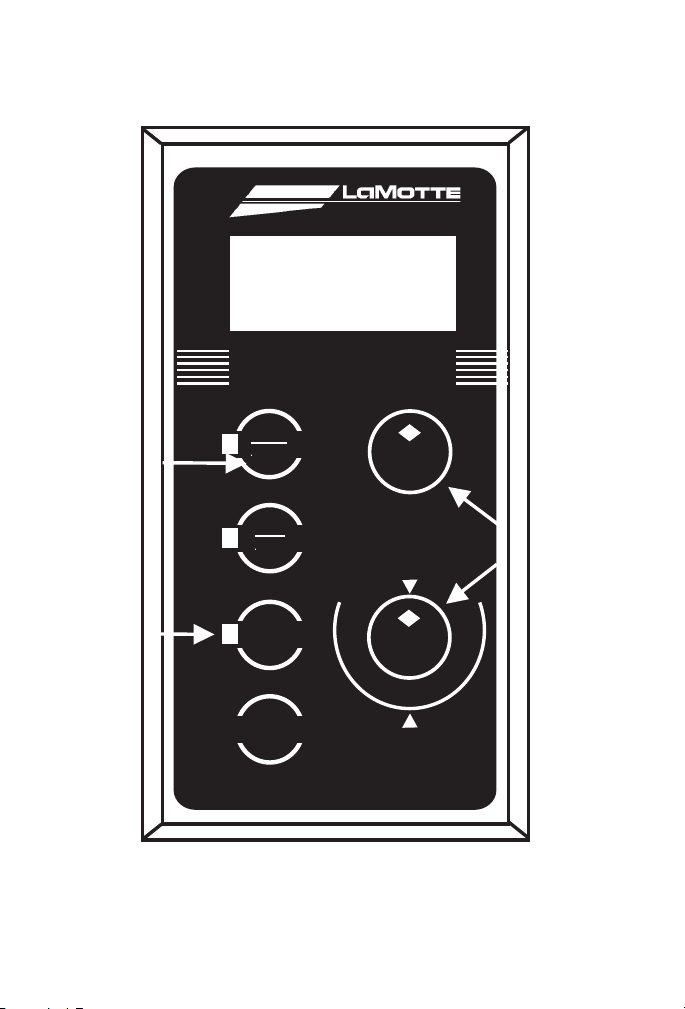
DIGITAL DISPLAY
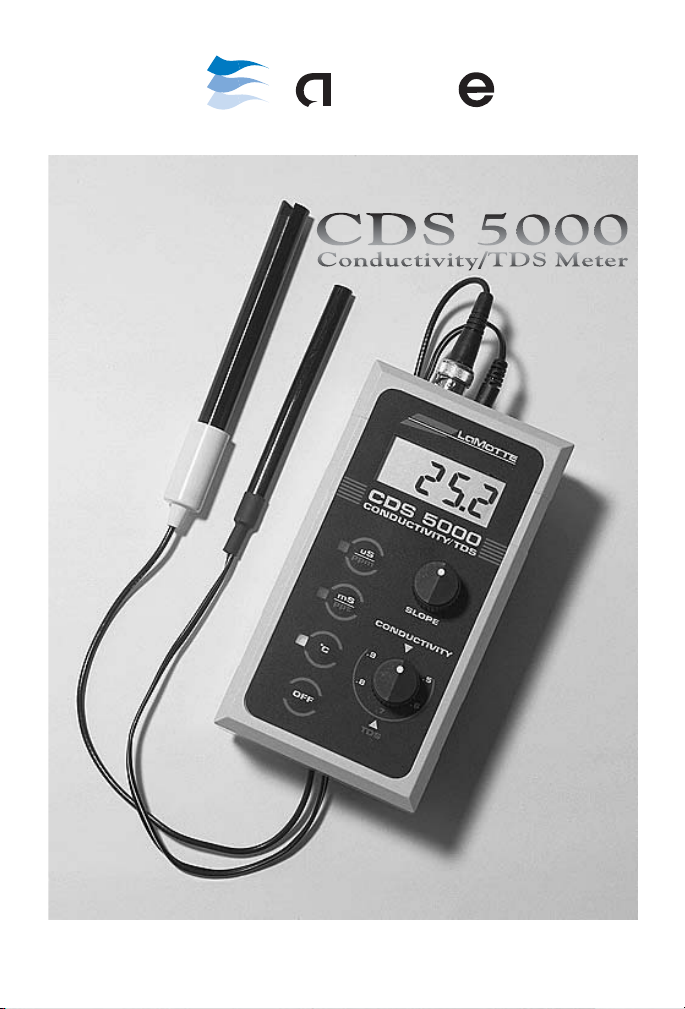
CDS 5000
CONDUCTIVITY/TDS
.5
.6
.7
.8
.9
uS
ppm
mS
ppt
°C
OFF
SLOPE
CONDUCTIVITY
TDS
Controls Used
To Calibrate
Light
Indicates
Currently
Active Mode
Press Button
To Select
Operating
Mode
2
Page 3

CDS 5000
L
Mott
CONDUCTIVITY/TDS METER
CODE 1752-01
TABLE OF CONTENTS
Conductivity.......................................................................................... 4
Meter Basics ........................................................................................... 5
Meter Specifications............................................................................... 6
Calibrating ............................................................................................. 7
Testing Water......................................................................................... 8
Testing Salinity ...................................................................................... 9
Testing Soil........................................................................................... 12
Maintaining the Meter......................................................................... 13
Warranty Information .......................................................................... 15
3
Page 4

CONDUCTIVITY
Conductivity is defined as the ability of a solution to conduct an electrical
current, or the reciprocal of the solution’s ability to resist the current. This
current is conducted by electrically charged particles called ions, which
are present in almost all solutions. Different solutions have different kinds
and amounts of ions: distilled water has very few ions, and therefore a low
conductivity, while sea water has a large number of ions, and a high
conductivity.
Although a conductivity reading provides an overall measurement of the
ionic content of a solution, it is not possible to distinguish the specific
amounts of individual ions. For this reason, conductivity is often used to
measure the total dissolved solids (TDS) of a solution. TDS is defined as
the amount of solids which will pass through a 45 micron filter. Rather
than filtering a solution, the TDS can be estimated by multiplying the
conductivity measurement by a predetermined factor. This factor, which is
determined gravimetrically, will fall between 0.55 and 0.9; 0.7 is a
commonly used factor.
The conductivity measurement can also be used to estimate the salinity of
water, or the total amount of all salts dissolved in the water. Typically, the
conductivity reading is converted to salinity using charts, such as the one
found on page 10. These charts are based on water containing the same
amount and proportion of ions as standard seawater, so this form of
measurement is most effective for low concentrations and dilutions of
seawater.
Conductivity is measured in microsiemens per centimeter (msiemens/cm).
Siemens are also called mhos. In waters of higher conductivity,
msiemens/cm may be mul million. Therefore, using the information
discussed above:
msiemens/cm x 0.7 = ppm TDS
Salinity is usually measured in parts per thousand (ppt). The chart on page
10can be used to convert conductivity readings to salinity.
Because it is a quick, reliable, and inexpensive way of monitoring the
ionic content of a solution, conductivity measurements are widely used in
many areas of water testing, from environmental monitoring to municipal
water supplies to many industrial applications.
4
Page 5

METER BASICS
Conductivity is measured using a probe which contains two electrodes,
separated by a fixed distance. When a voltage is applied from the meter
across the electrodes, the ions in solution conduct a current, which flows
between the electrodes. The greater the concentration of ions in the
solution, the larger the current generated and the higher the conductivity.
Likewise, the smaller the concentration of ions, the lower the
conductivity. The meter converts the current measured to a conductivity
reading.
Over time the electrodes may become dirty or fouled with contaminants
from the sample. For specific probe cleaning instructions for the CDS
5000 see Maintaining The Meter on page 13.
Conductivity measurements are very dependent on temperature. The
ability of the ions to move through the solution, and conduct the current,
is related to the temperature of the solution. As the temperature rises, the
ions move more quickly through the solution, increasing the conductivity;
likewise as the temperature decreases the ions move more slowly and the
conductivity decreases. Since the conductivity of the same solution can
change by as much as 2%/°C, accurate temperature measurements must
be made simultaneously to the conductivity reading. The CDS 5000
includes a temperature probe to measure the temperature.
To make conductivity readings taken at different times and places
comparable, measurements are often converted to what the conductivity
of the solution would be at 25°C. The CDS 5000 automatically makes this
conversion before providing a final reading.
5
Page 6

METER SPECIFICATIONS
Range 1-199.9 mS/cm
200-1999 mS/cm
2-19.99 mS/cm
20-199.9 mS/cm
0to50°C
Resolution ±0.1
±1
±10
±100
Readout 3
1
digit LCD
2
Controls SLOPE
CONDUCTIVITY
mS/ppm
mS/ppt
°C
OFF
Temperature
Automatic by separate probe
Compensation
Probe Carbon electrodes; 3 ft. cable
Power 1604A Alkaline Battery (9 volt)
3.5 mm jack adapter
7
1
Size 5
“x3
8
3
”x1
“(15cmx8cmx5cm)
4
4
ACCESSORIES
Description Code #
AC Adapter 1708
Funnel 0459
Filter Paper 0465
Cond. Std., 0.0005M KCl, 74 mmhos/cm 6416-L
Cond. Std., 0.005M KCl, 718 mmhos/cm 6417-L
Cond. Std., 0.01M KCl, 1,413 mmhos/cm 6354-L
Cond. Std.,0.05M KCl, 6,668 mmhos/cm 6418-L
Cond. Std., 0.5M KCl, 58,640 mmhos/cm 6419-L
6
Page 7

CALIBRATING
The CDS 5000 is precalibrated at the factory; set both the TDS knob and
the SLOPE knob to the 12 o’clock position and proceed. This procedure
will give results within ±10% of the actual reading. For more accurate
results, follow the procedure below.
1. Press “°C” button to turn the meter on.
2. Set TDS knob to the 12 o’clock position.
1
3. Insert temperature and conductivity probes at least
conductivity standard.
“into
2
4. Gently stir with conductivity probe until reading stabilizes. Press
“mS/ppm” or “mS/ppt” button.
5. Adjust SLOPE knob until display reads conductivity of chosen
standard. The CDS 5000 is now calibrated and ready for use.
LaMotte offers several ranges of conductivity standards. Choose the
standard most appropriate for your testing needs and order using the four
digit code number listed.
STANDARDS
Description Code #
Cond. Std., 0.0005M KCl, 74 mmhos/cm 6416-L
Cond. Std., 0.005M KCl, 718 mmhos/cm 6417-L
Cond. Std., 0.01M KCl, 1,413 mmhos/cm 6354-L
Cond. Std.,0.05M KCl, 6,668 mmhos/cm 6418-L
Cond. Std., 0.5M KCl, 58,640 mmhos/cm 6419-L
7
Page 8

TESTING WA TER
CONDUCTIVITY
1. Press “°C” button to turn the meter on.
2. Set TDS and SLOPE knobs to the 12 o’clock position.
NOTE: If meter was calibrated according to procedure on page 7,
leave SLOPE knob set in the same position.
3. Insert temperature and conductivity probes at least 1/2" into sample.
4. Gently stir with conductivity probe until reading stabilizes. Press
“mS/ppm” button. Record reading as msiemens/cm.
5. If a 1 appears on the far left side of the display, the reading is out of
range. Repeat procedure using “mS/ppt” button. Record as
msiemens/cm. To convert to msiemens/cm, multiply reading by 1000.
Record as msiemens/cm.
6. Press “OFF” button when finished testing. Rinse probe with distilled
water and dry thoroughly before storing.
TOTAL DISSOLVED SOLIDS
1. Set TDS knob to desired multiplication factor.
NOTE: 0.7 is a commonly used multiplication factor.
2. Press “°C” button to turn the meter on.
3. Set SLOPE knob to the 12 o’clock position.
NOTE: If meter was calibrated according to procedure on page 7,
leave SLOPE knob set in the same position.
4. Insert temperature and conductivity probes at least 1/2" into sample.
5. Gently stir with conductivity probe until reading stabilizes. Press
“mS/ppm” button. Record reading as msiemens/cm.
6. If a 1 appears on the far left side of the display, the reading is out of
range. Repeat procedure using “mS/ppt” button. Record as
msiemens/cm. To convert to msiemens/cm, multiply reading by 1000.
Record as msiemens/cm.
7. Press “OFF” button when finished testing. Rinse probe with distilled
water and dry thoroughly before storing.
8
Page 9

TESTING SALINITY
1. Press “°C” button to turn the meter on.
2. Set TDS and SLOPE knobs to the 12 o’clock position.
NOTE: If meter was calibrated according to procedure on page 7,
leave SLOPE knob set in the same position.
3. Insert temperature and conductivity probes at least 1/2" into sample.
4. Gently stir with conductivity probe until reading stabilizes. Press
“mS/ppt” button. Record reading as msiemens/cm.
5. Using chart on the following page, convert conductivity reading to
salinity . Record as ppt Salinity.
6. Press “OFF” button when finished testing. Rinse probe several times
with distilled water and dry thoroughly before storing.
9
Page 10

FOR CHANGING CONDUCTIVITY INTO SALINITY
CONVERSION TABLE
Conductivity Salinity
0°C 5°C 10°C 15°C 20°C 25°C 30°C
0
1.200 1.400 1.500 1.700 2.000 2.200 2.400 1
2.220 2.500 2.900 3.300 3.700 4.100 4.500 2
3.200 3.700 4.200 4.700 5.300 5.900 6.500 3
4.100 4.700 5.400 6.100
6.900
7.600 8.400 4
5.000 5.800 6.600 7.500 8.400 9.300 10.3005
5.900 6.800 7.900 8.800 9.900 11.000 12.1006
6.700 7.800 8.900 10.100 11.300 12.600 13.9007
7.600 8.800 10.100 11.400 12.800 14.200 15.7008
8.500 9.800 11.200 12.700 14.200 15.800 17.4009
9.300 10.800 12.300 13.900 15.600 17.300 19.10010
10.200 11.800 13.400 15.200 17.000 18.900 20.80011
11.000 12.800 14.500 17.600 18.900 20.400 22.50012
11.900 13.700 15.600 18.900 19.700 21.900 24.10013
12.600 14.600 16.700 20.100 21.100 23.400 25.80014
00
13.400 15.600 17.800 20.100 22.400 24.900 27.40015
14.200 16.400 18.800 21.200 23.800 26.400 29.10016
15.000 17.400 19.800 22.400 25.100 27.800 30.70017
15.800 18.300 20.900 23.600 26.400 29.300 32.30018
16.600 14.200 21.900 24.800 27.700 30.700 33.90019
17.400 20.100 23.000 25.900 29.000 32.200 35.50020
18.200 21.100 24.000 27.100 30.300 33.600 37.00021
Page 11

Conductivity Salinity
0°C 5°C 10°C 15°C 20°C 25°C 30°C
0
19.000 22.000 25.100 28.300 31.600 35.000 38.60022
19.800 22.900 26.100 29.400 32.900 36.500 40.10023
20.600 23.800 27.100 30.600 34.200 37.900 41.70024
21.400 24.700 28.100 31.700 35.400 39.300 43.20025
22.100 25.500 29.100 32.800 36.700 40.700 44.80026
22.800 26.400 30.100 33.900 37.900 42.100 46.30027
23.600 27.300 31.100 35.100 39.200 43.500 47.80028
24.400 28.100 32.100 36.200 40.400 44.800 49.40029
25.200 29.000 33.100 37.300 41.700 46.200 50.90030
00
10
Page 12

FOR CHANGING CONDUCTIVITY INTO SALINITY
CONVERSION TABLE
Conductivity Salinity
0°C 5°C 10°C 15°C 20°C 25°C 30°C
0
00
26.800 30.900 35.100 39.600 44.200 49.000 53.900 32
27.500 31.700 36.100 40.700 45.400 50.300 55.400 33
28.300 32.600 37.100 41.800 46.700 51.700 56.800 34
29.100 33.500 38.100 42.900 47.900 53.000 58.300 35
29.700 34.200 39.000 44.000 49.100 54.400 59.800 36
30.500 35.100 40.000 45.100 50.300 55.700 61.300 37
31.200 36.000 41.000 46.200 51.500 57.100 62.800 38
32.000 36.800 41.900 47.200 52.700 58.400 64.200 39
32.700 37.700 42.900 48.300 53.900 59.700 65.700 40
Data derived from the equation of P.K. Weyl, Limnology and Oceanography;9,75
(1964).
11
Page 13

TESTING SOIL
The Total Dissolved Solids (TDS) level of soil samples can be determined
using the CDS 5000. A soil extraction is made using distilled water, and
the TDS level measured.
1. Fill a 50 mL beaker with sample soil. Tap lightly to eliminate trapped
air. Remove excess soil from the surface.
2. Empty beaker into a 250 mL widemouth flask. Add 100 mL of
distilled water. Stopper and shake vigorously. Wait 30 minutes.
NOTE: During the waiting period, vigorously shake the sample three
or four times.
3. Filter contents of flask, collecting filtrate in a beaker or other suitable
container.
NOTE: LaMotte Company offers a funnel (order code 0459) and
filter paper (order code 0465) which can be used for this filtration.
4. Set TDS knob to desired multiplication factor.
NOTE: 0.7 is a commonly used multiplication factor.
5. Press “°C” button to turn the meter on.
6. Set SLOPE knob to the 12 o’clock position.
NOTE: If meter was calibrated according to procedure on page 7,
leave SLOPE knob set in the same position.
7. Insert temperature and conductivity probes at least 1/2" into sample.
8. Gently stir with conductivity probe until reading stabilizes. Press
“mS/ppm” button. Record reading as msiemens/cm.
9. If a 1 appears on the far left side of the display, the reading is out of
range. Repeat procedure using “mS/ppt” button. Record as
msiemens/cm. To convert to msiemens/cm, multiply reading by 1000.
Record as msiemens/cm.
10. Press “OFF” button when finished testing. Rinse probe with distilled
water and dry thoroughly before storing.
12
Page 14

MAINTAINING THE METER
Adjust This
Potentiometer
REPLACING THE BATTERY
When “BAT” appears on the display, the battery should be replaced. The
temperature reading will be the first function to be affected by a low
battery.
1. Use a #1 Phillips head screwdriver to remove four screws on the back
of the meter case.
2. Gently lift back panel from meter .
3. Lift battery from bottom of meter. Remove from connector.
4. Snap new battery onto connector.
NOTE: The CDS 5000 uses a type 1604A (9 volt) battery .
5. Lower battery into compartment. Replace back panel and screws.
AC ADAPTER
An AC adapter is available for use with the CDS 5000. Order as code
#1708. Insert connector into small hole next to the probe connector.
CLEANING THE PROBE
Page 15

The graphite probe may occasionally become dirty and need to be
cleaned. After each use the probe should be thoroughly rinsed with
distilled water. If further cleaning is necessary, the probe can be washed
with a mild detergent, and then thoroughly rinsed with distilled water.
Always thoroughly dry the probe before storing.
13
Page 16

REPLACING THE PROBE
If the probe cannot be adequately cleaned, or becomes damaged, it must
be replaced. When a new probe is attached to the meter, the CDS 5000
must be recalibrated using the following procedure. Do not allow the CDS
5000 to contact any conductive surfaces while performing this procedure.
1. Set SLOPE and TDS knobs to the 12 o’clock position.
2. Use a Phillips head screwdriver to remove four screws from back of
meter. Remove back from meter.
3. Follow the Conductivity testing procedure described on page 8 to
measure the conductivity of a chosen standard. Choose the standard
that is closest to the value of the solutions commonly measured.
4. Using a small, flat edge screwdriver, adjust the top potentiometer
(indicated in the diagram) until value of standard solution is
displayed.
NOTE: Only adjust the top potentiometer; adjusting any other
potentiometer voids the meter’s warranty. If these other
potentiometers are adjusted, the meter must be returned to LaMotte
for repair.
5. Replace back on meter and replace the four screws. The CDS 5000 is
now calibrated and ready for use.
14
Page 17

WARRANTY INFORMATION
REPAIRS
If it is necessary to return the instrument for repair, contact LaMotte
Company at 1-800-344-3100 for a return authorization number.
INSTRUMENT GUARANTEE
This instrument, excluding the probe, is guaranteed to be free of defects in
material and workmanship for one year from date of original purchase. If,
in that time, it is found to be defective, it will be repaired without charge,
except for transportation expenses. This guarantee does not cover the
batteries.
This guarantee is void under the following circumstances:
operator’s negligence
•
improper application
•
unauthorized servicing
•
LIMITS OF LIABILITY
Under no circumstances shall LaMotte Company be liable for loss of life,
profits, or other damages incurred through the use of misuse of their
products.
PA CKAGING AND DELIVERY
Experienced packaging personnel at LaMotte Company assure adequate
protection against normal hazards encountered during shipping. After the
product leaves the manufacturer, all responsibility for its safe delivery is
assured by the transporter. Damage claims must be filed immediately with
the transporter to receive compensation for damaged goods.
15
Page 18

LaMOTTE COMPANY
Helping People Solve Analytical Challenges
PO Box 329 • Chestertown • Maryland • 21620 • USA
800-344-3100 • 410-778-3100 (Outside U.S.A.) • Fax 410-778-6394
Visit us on the web at www.lamotte.com
SM
61752-01 · 10/02
 Loading...