

Page 1
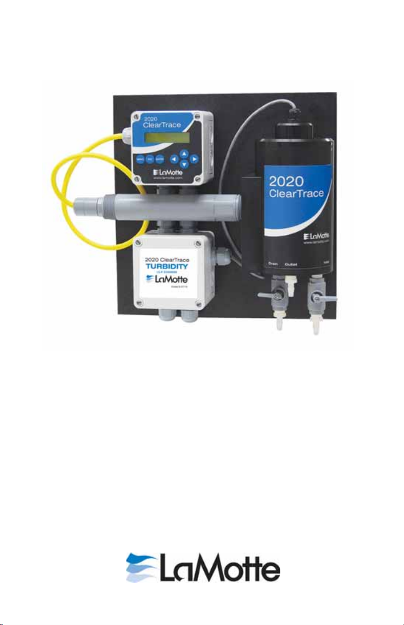
2020 ClearTrace
In-line Turbidity System
Code 5-0113-24V
Code 5-0113-110V
Page 2

Page 3

Preface
This instruction manual serves to explain the use of the LaMotte 2020 ClearTrace
Inline Turbidity System and is written to cover as many applications as possible.
Please do not hesitate to contact LaMotte or an authorized LaMotte representative
with questions or concerns.
The information presented in this instruction manual is subject to change without
notice as improvements are made, and does not represent any commitment
whatsoever on the part of LaMotte.
LaMotte cannot accept any responsibility for damage or malfunction of the sensor
due to improper use.
Contact Information
Mail: LaMotte Company • PO Box 329 • Chestertown, MD 21620
Phone: 800-344-3100 • 410-778-3100
Fax: 410-778-6394
Email: csr@lamotte.com
Website: www.lamotte.com
2
Page 4

Safety Information
The LaMotte 2020 ClearTrace Turbidity System shall
be installed and operated only in the manner specified.
Only a skilled, trained or authorized person should
carry out installation, setup and operation of the
system.
Before using the system, make sure that is connected as
specified. Failure to do so may result in permanent
damage to the system of its components.
Protection against electric shock will be achieved only
by observance of the corresponding installation rules.
3
Page 5

Table of Contents
Preface ................................. 2
Contact Information ..........................2
Safety Information ........................... 3
1. Introduction ............................5
1.1 General Information .......................5
1.2 Intended Use ...........................6
1.3 Safety Instructions ........................ 6
1.4 Removal from Service/Correct Disposal .............6
2. Product Description ........................ 7
2.1 Drinking Water Turbidity ....................7
2.2 Calibration Kits .......................... 7
2.3 Replacement Parts ........................ 8
3. Mounting, Wiring, and Plumbing ................. 9
3.1 Mounting ............................. 9
3.2 Plumbing............................. 10
3.3 Valve Position for Operation ..................10
3.4 Wiring For 24 VDC and 110VAC Power ............11
3.5 Sample Chamber Details .................... 14
4. Measure Screen Overview .................... 15
5. Menu Structure.......................... 16
6. Calibration ............................ 19
6.1 Span Calibration ........................ 19
6.2 Zero Calibration ......................... 22
6.3 Temperature Calibration ....................24
7. Configuration ...........................26
8. DataStick Comms Menu .....................27
9. Analog Output(s)......................... 27
11. Help Menu ............................30
12. Reset AV 38 ........................... 31
13. Performance Specifications ................... 31
14. Limited Warranty ........................33
4
Page 6
1. INTRODUCTION
1.1. General Information
Thank you for purchasing the LaMotte 2020 ClearTrace Inline Turbidity
System.
The product is designed for continuous use in industrial process
applications and complies with safety regulations currently in force.
Improper use could lead to hazards for the user or a third-party, and/or
adverse effects to the plant or other equipment.
LaMotte does not accept any liability for damage that may arise if
information in this manual is not followed. Therefore, the operating
instructions and specifications must be read and understood by all persons
involved in installation and operation of this equipment.
This manual identifies safety instructions and additional information by
means of the following symbols:
This symbol draws attention to safety
instructions and warnings of potential
danger, which if neglected, could result in
injury to persons and/or damage to property.
This symbol identifies additional
information and instructions, which if
neglected, could lead to inefficient
operation and possible loss of production.
It is recommended that this manual be made accessible to everyone who
may need it as a reference.
Please contact LaMotte or an authorized LaMotte representative with any
questions.
5
Page 7

1.2. Intended use
The LaMotte 2020 ClearTrace Inline Turbidity System is used for
continuous monitoring of low-range turbidity in drinking water
applications. The system also measures water temperature.
Data is reported through a local display and a scalable 4-20 milliamp
current output.
Any other use, or use not mentioned here, that is incompatible with the
technical specifications is deemed inappropriate. The operator is solely
responsible for any damage arising from such use.
Other prerequisites for appropriate use include:
Observing the instructions, notes and requirements set out in this
•
instruction manual.
Observing all local safety regulations.
•
Observing all warnings and cautions in the documentation regarding
•
all products used in this measurement system, including the sensor,
mounting hardware, AV38 electronics and cabling.
Observing the prescribed environmental and operational conditions.
•
Observing chemical compatibility with all wetted materials.
•
1.3. Safety Instructions
The Turbidity System should be installed and operated
only by personnel familiar with the sensor and qualified for
such work.
A defective Turbidity System should be returned to
LaMotte for repair or replacement. Contact LaMotte to
obtain a Return Material Authorization (RMA) number.
No modifications to the Turbidity System are allowed. The
manufacturer/supplier accepts no responsibility for damage
caused by unauthorized modifications. The risk is borne
entirely by the user.
1.4. Removal from Service / Correct Disposal of the
Turbidity System
Removal from Service
•
Disconnect the cable wiring from the controller terminal block.
•
Remove the Turbidity System from the mounting hardware.
Correct Disposal of Unit
•
When the Turbidity System is taken out of service, observe the local
environmental regulations for correct disposal.
6
Page 8

2. PRODUCT DESCRIPTION
2.1 Drinking Water Turbidity
The LaMotte 2020 ClearTrace Inline Turbidity System continuously
monitors low-range turbidity and temperature in drinking water
applications.
In the standard system configuration, data is reported through a local
display and a scalable4–20milliamp current output. All functions can be
accessed through a digital network with or without the local display
interface.
The Turbidity System uses a pre-calibrated turbidity probe mounted in a
DataStick and attached to a sample chamber specifically designed to
prepare water for low-range turbidity measurements. The chamber removes
bubbles from the water sample so that solid particles can be accurately
detected. Because the chamber volume is only 135 milliliters, only a small
amount of a turbidity standard is necessary to perform EPA mandated
calibrations.
A white light source in the chamber lid illuminates suspended particles
with a collimated white light. The chamber lamp will provide collimated
white light for up to two years and is easily changed from the top of the
system.
Measurement data from the turbidity probe is communicated through the
DataStick communication adapter for direct computer communications.
2.2 Calibration Kits
Calibration kits containing calibration standards and accessories are
available for use with the 2020 ClearTrace.
Code 5-0114
1 liter 0.0 NTU, calibration standard
1 liter 20.0 NTU, calibration standard
2 squirt bottles, for standards
2 cleaning swabs
Code 5-0115
1 gallon 0.0 NTU, calibration standard
1 gallon 20 NTU, calibration standard
2 spigots, for dispensing standards
2 squirt bottles, for standards
2 cleaning swabs
7
Page 9

2.3 Replacement Parts
Code 5-0124 Bulb and cable assembly
Code 5-0125 Sample chamber lid, without bulb
Code 5-0126 Replacement sample chamber
Code 5-0127 DataStick
Code 5-0126 Turbidity Probe
Code 5-0116 Turbidity standard, 0.0 NTU, 1 liter
Code 5-0117 Turbidity standard, 0.0 NTU, 1 gallon
Code 5-0118 Turbidity standard, 1.0 NTU, 1 liter
Code 5-0119 Turbidity standard, 1.0 NTU, 1 gallon
Code 5-0120 Turbidity standard, 10.0 NTU, 1 liter
Code 5-0121 Turbidity standard, 10.0 NTU, 1 gallon
Code 5-0122 Turbidity standard, 20.0 NTU, 1 liter
Code 5-0123 Turbidity standard, 20.0 NTU, 1 gallon
8
Page 10
3. MOUNTING, WIRING AND PLUMBING
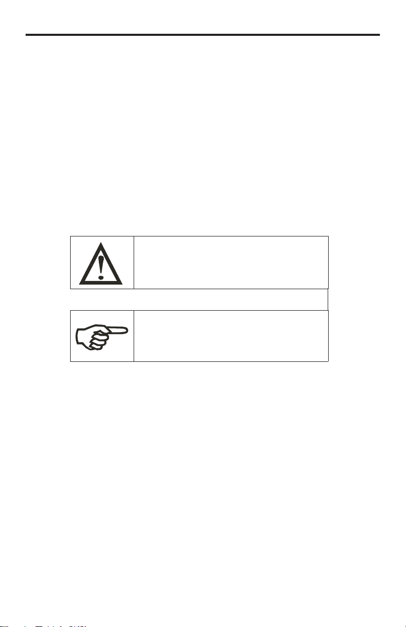
Figure 3.1: Wall mounting Clearances
3.1 Mounting
The 2020 ClearTrace Turbidity System is mounted on a 12 inch x 12 inch
panel with four ¼ inch mounting holes. Use ¼ inch bolts with washers to
mount the panel to a wall. Make sure the sample chamber is level and
plumb to insure proper water levels are maintained in the sample chamber.
It is important to note that the system must be fixed securely to the wall to
insure the chamber does not move when handled or touched.
Mounting tools and equipment:
•
½ inch Drill with drill bit for appropriate wall anchor.
•
Four ¼ diameter bolts – 1.5 inches long.
•
Four ¼ inch ID flat washers
•
Wrench to turn bolts
•
Level to insure the system is level when mounted
General Mounting Instructions:
1. Place the 12x12 inch panel on the wall where it is to be mounted and
mark the placement of the upper left hole.
2. Drill a mounting hole for the upper left corner with a masonry drill
bit.
3. Mount the Turbidity System with the upper left bolt.
4. Using a level, rotate the system until level, then mark the other three
mounting holes.
9
Page 11
5. Rotate the Turbidity System out of the way and drill the other three
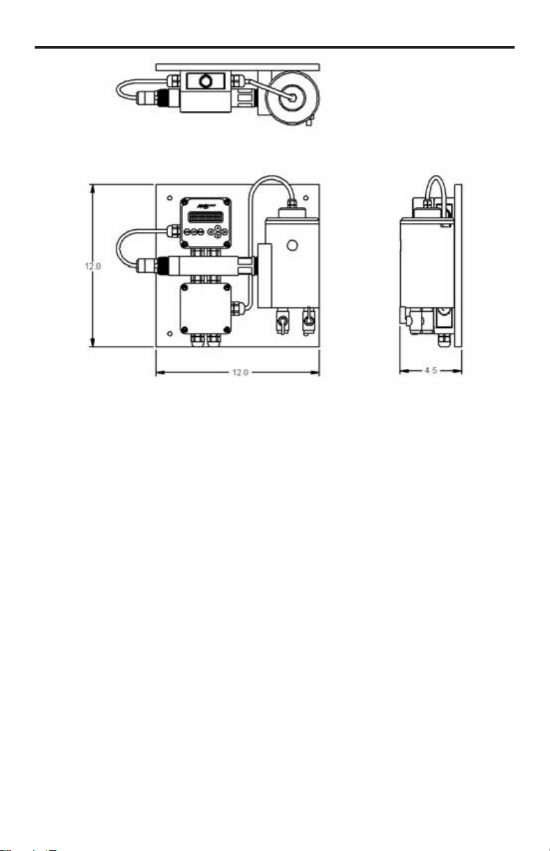
Measure
• Inlet valve open
• Drain valve closed
Water goes in the
INLET and out the
OUTLET. The sample
chamber should be full
Drain Sample Chamber
• Inlet valve closed
• Drain valve open
Drain sample chamber
and wipe clean prior
to calibration.
Calibration
• Inlet valve closed
• Drain valve open
When sample chamber
is empty and clean, pour
in 20 NTU standard until
it overflows to the
OUTLET (approx.
135 mL).
mounting holes.
6. Place all four bolts with washers and tighten. Use shims if necessary
to insure the sample chamber is level.
3.2 Plumbing
The Turbidity System has an INLET, an OUTLET and a DRAIN.
Barb fittings are provided for the INLET and OUTLET in the event that
3/8 inch ID tubing is used.
When piping is used instead of tubing, remove the barb fittings to install ¼
inch NPT threaded pipe for the INLET, OUTLET and DRAIN.
OUTLET and DRAIN Plumbing Recommendations: Use straight ¼ inch
NPT threaded pipe that extends to a vented drain. Pipe restrictions that
result in back pressure for OUTLET and DRAIN are not allowed.
INLET Plumbing Recommendations: Use 3/8 ID tube or ¼ inch NPT
threaded pipe from sample source.
Flow rate must be between 250 to 750 ml/min (4 to 12 gph). If the source
is under pressure, use an appropriate flow or pressure valve to obtain
consistent flow. The turbidity sample chamber has an overflow weir that
must not be restricted.
3.3 Valve Position for Operation
10
Page 12

3.4 Wiring For 24 VDC and 110 VAC Power
T urbidity User
Junction Box
Lamp assembly
screws into sample
chamber lid
Lamp cable connection
Terminal Connection to AV38
USER Terminal Connections:
See next page for wiring tables
24 VDC
or
110 VAC
Lamp
24 VDC or 110 VAC
Access to all User wiring is through the ¼ DIN junction box in the lower
left on the mounting panel.
The standard on-line turbidimeter requires 24 VDC for power and typically
draws 270 mA (6.5 watts) or optionally requires 100-240 VAC at 50/60 Hz
for power and typically draws up to 250 mA (10 watts).
Pg11 and Pg16 punch out conduit holes are provided for user terminal
connections. We supply Pg11 cord grips that can be removed.
Note: Loop 2 and Relay options are not currently available on 2020
ClearTrace System.
11
Page 13

USER WIRING FOR: 1 Current Loop without Host Communications
100-240 VAC Power Cable Wiring:
1. 100-240 VAC, 50/60 Hz power is wired to the wider-spaced
strip on left side of terminals.
2. Typically Black wire to 'LINE', White wire to 'NEUTRAL',
and Green wire to 'EARTH'
Lamp cable connection.
Red wire to 'LAMP+'
Black wire to 'LAMP-'
Terminal Connections
to AV38; .
Red wire to '+24V' terminal
Black wire to 'GND'
24 VDC power
Terminal Wiring
1 24VDC or 110 VAC from Power Supply
2 Ground from Power Supply
3
4
5 Earth Ground from Power Supply
6 Current Loop 7 Current Loop +
8
9
10
11
12
Note: Current Loop Requires 24 VDC or 110 VAC supply.
USER WIRING FOR: 24 VDC or 110 VAC Power
AC-Powered Models:
The AC-powered ClearTrace Tubidimeter comes with a Junction Box below the two
terminal blocks when ordered with one or two 4-20 mA analog outputs and/or host
comminications. If relays are ordered, a third terminal block is present.
12
Page 14

USER WIRING FOR: Digital Communications to Host Computer with 2 Outputs
and Relay
Terminal Wiring
1 Red wire from Host Network (+24 VDC or 110 VAC)
2 BLACK wire from Host Network (Network Ground)
3 White wire from Host Network
4 Blue wire from Host Network
5 Shield wire from Host Network
6 OUTPUT 1 (-)
7 OUTPUT 1 (+)
8 OUTPUT 2 (-)
9 OUTPUT 2 (+)
10 Relay – Normally Open Terminal
11 Relay – Common Terminal
12 Relay – Normally Closed Terminal
Note: Output 2 and Relay options are not currently available on 2020
ClearTrace System.
13
Page 15

3.6 Sample Chamber Details
Exterior marker to
align lid with sample
chamber
Sample Chamber Lid with
integral lamp assembly
Alignment hole
The alignment peg
on the Sample Chamber
must line up with the
alignment hole in
the lid.
Alignment peg
Chamber Lid with Lamp
Chamber Body
Sample Chamber
with bubble trap
Sample Chamber
with Lid in Place
Keep aperture dry
Sample Chamber
Bubble Trap
DataStick*with
Optical Sensor
Head can be
removed and
replaced.
TM
Lamp Assembly
The lamp assembly
screws into the lid.
The cable is routed
to the user terminal
box.
Lamp with Cable
Chamber Lid
The sample chamber is designed for easy access and maintenance.
The chamber lid is lifted to gain access to the sample chamber. Set it on
top of the AV38 during chamber maintenance. When replacing the lid, it
should be aligned using the exterior alignment markers on the front edge of
the chamber and the lid.
*DataStick is a registered trademark of Thermo Fisher Scientific Inc. and
its subsidiaries.
14
Page 16

4. MEASURE SCREEN OVERVIEW
0.035 NTU AB
30.8 °C DS1: 6
MENU ESC ENTER
Figure 3.1: The elements of the measure screen
t
t
t
t
Figure 3.2: The measure screen when the Sensor
Head is absent.
Sensor Head
Absent
MENU ESC ENTER
t
t
t
t
Figure 3.3: The measure screen when the
DataStick is absent.
DataStick
Absent
MENU ESC ENTER
t
t
t
t
The AV38 user interface is
shown in Figure 3.1. It
consists of an LCD module
that contains two lines of 16
alphanumeric characters and
seven keys to navigate the
menu. The contrast of the
LCD module can be adjusted
by simultaneously pressing
the escape and up-arrow keys
(for more contrast) or the escape and down-arrow keys (for less contrast).
When the DataStick and
communications adapter are
connected to the AV38
display but the optical sensor
head is absent, the measure
screen indicates the fault as
shown in Figure 3.2.
When the DataStick or
communications adapter are
not connected to the AV38
display, the measure screen
indicates the fault as shown
in Figure 3.2.
15
Page 17

5. MENU STRUCTURE
Pressing the menu key while a measure screen is displayed accesses the
main menu. The items in the main menu are the same regardless of the
type of sensor head that is installed in the DataStick. Table 4.1 shows all
accessible functions including optional features.
Note: Not all optional features are currently available on 2020 ClearTrace
System.
Main Menu Option
Calibrate
(Station Number)
Configure
(Station Number)
DataStick Comms
Chlorine Configure
Hold Outputs
Analog Output 1
Analog Output 2 (option)
PID Controller
Relay A (option)
Relay B (option)
Help
Reset AV38
Exit
The main menu is navigated using the up/down arrows to display a desired
function. The (=) symbol is used to indicate main menu choices.
To select a menu choice, press the ENTER key when the desired choice is
displayed.
To return to the measure screen, press the ESC key.
Whenever there is a value to be entered or a choice to be made, the second
line of the display will be surrounded by parentheses (( )). The name of
the value being entered or choice being made will appear on the upper line
of the screen and be appended with a question mark (?) to indicate that the
user is to provide input. Figure 4.1 shows the list of standard menu choices
and optional menu choices in the context of the AV38 display
presentation.
Function
Sensor calibration choices are automatically available for
installed sensor head.
Enter the MENU from the measure display of interest –
station in lower right.
Configuration choices are automatically available for the
installed sensor head.
Enter the MENU from the measure display of interest –
station in lower right.
Not currently available
Not currently available
Holds the 4-20 mA and Relay outputs
Set 4 mA and 20 mA values. Calibrate and test the current
output with a meter.
Not currently available
Not currently available
Not currently available
Not currently available
Indicates AV38 software version
Resets AV38 configuration to default current output, relay
and PID settings.
Returns to the measure screen
16
Page 18

Main Menu
Calibrate
MENU ESC ENTER
Configure
DataStick Comms
Analog Output 1
Analog Output 2
Relay A
Relay B
Help
Reset AV38
Exit
Main Menu
Optional Features
t
t
t
t
t
ttttttt
t
Main Menu
Calibrate
MENU ESC ENTER
Configure
DataStick Comms
Analog Output
Help
Reset AV38
Exit
Main Menu
Standard
t
t
t
t
t
ttttt
t
Main Menu
Calibrate
MENU ESC ENTER
t
t
t
t
t
Main Menu
Configure
MENU ESC ENTER
t
t
t
t
t
Main Menu
DataStick Comms
MENU ESC ENTER
t
t
t
t
t
ESC
Figure 4.1: The main menu (standard and optional feature lists)
To illustrate navigation through the main menu the following sequence of
down arrow key presses is shown. The up arrow can always be used to scroll
up through the list.
A pressed key is identified by a gray background, e.g.,.
From the measure screen,
press MENU to display the
list of options. Generally,
Calibration will be the first
option. To select a
calibration function, press
ENTER. Press the down
arrow to scroll through the
list. Press ESC to return to
the measure screen.
Pressing the down arrow from
Calibration will display
Configure. To select
Configure functions, press
ENTER To continue scrolling
the list, press the down arrow.
Press ESC to return to the
measure screen.
Pressing the down arrow from
Configure will display
DataStick Comms. To select
DataStick Comms functions,
press ENTER. To continue
scrolling the list, press the
down arrow. Press ESC to
return to the measure screen.
Note: The DataStick Comms
option is not available on
2020 ClearTrace System.
17
Page 19

Pressing the down arrow from
Main Menu
Help
MENU ESC ENTER
t
t
t
t
t
Main Menu
Exit
MENU ESC ENTER
t
t
t
t
t
Main Menu
Reset AV38
MENU ESC ENTER
t
t
t
t
t
Main Menu
Analog Output
MENU ESC ENTER
t
t
t
t
t
DataStick Comms will display
Analog Output. To select
analog output functions, press
ENTER To continue scrolling
the list, press the down arrow.
Press ESC to return to the
measure screen.
Pressing the down arrow from
Analog Output will display
Help. To select Help
functions, press ENTER To
continue scrolling the list,
press the down arrow. Press
ESC to return to the measure
screen.
Pressing the down arrow from
Help will display Reset AV38.
To select Reset functions,
press ENTER To continue
scrolling the list, press the
down arrow. Press ESC to
return to the measure screen.
To return to the measure
screen press ENTER when in
the EXIT screen. Pressing
ESC from any screen will take
the user up one level. In this
example ESC will also take
the user to the measure
screen. Since this screen is at
the bottom of the main menu
list, the down arrow will not
work here. The up arrow can
be used to go back through
the list.
18
Page 20

6. CALIBRATION
Drain Chamber, Shut off Inlet
Drain and Inlet are shut off:
Ready to calibrate
Sample Chamber
with Lid Removed
Be careful to pour standard directly
into the SAMPLE CHAMBER.
Do not pour standard into the
Bubble trap.
During this operation, water will
remain int he BUBBLE TRAP and
it is not necessary to remove it.
Sample Chamber
Bubble Trap
Calibrate
1-Point Sample
MENU ESC ENTER
Zero
Temperature
Exit
t
t
t
t
t
tt
t
NOTE: The unit should be on for 30
minutes to allow the lamp to warm up
before begining calibrations or taking
measurements.
6.1. Span Calibration
To calibrate the span for the Turbidity
System:
1. Drain the sample chamber.
2. Shut off flow to the sample chamber.
3. Remove the chamber lid and place it
on top of the AV38.
4. Rinse the chamber with clean water and then with a small amount of
calibration solution. (See calibration kit instructions Code-5-0114 or
code 5-0015 for procedure.)
5. Shut off the Drain.
6. Fill the sample chamber with AMCO Clear Turbidity Standard, 20
NTU calibration solution. The standard should overflow the
OUTLET weir located about ¾ of the way to the top of the sample
chamber. As an alternative a formazin 20 NTU calibration standard
may be prepared from a stock solution of 4000 NTU formazin and
used within 24 hours. Refrigerate when stored.
7. After filling the sample chamber with the standard, wait for the
reading to settle (less than a minute depending on the filter setting).
8. Perform a 1-point
sample calibration as
shown in the following
menu tree.
The complete calibrate menu
for the turbidity and
suspended solids is shown.
Figure 5.15: The complete calibrate menu for turbidity
19
Page 21

From the measure screen,
41.32 NTU
Sensor ready?
MENU ESC ENTER
t
t
t
t
40.16 NTU
13.1 °C
MENU ESC ENTER
t
t
t
t
Main Menu
Calibrate
MENU ESC ENTER
t
t
t
t
t
Calibrate
1-Point Sample
MENU ESC ENTER
t
t
t
t
t
1-Point Sample?
( 20.00) NTU
MENU ESC ENTER
t
t
t
t
press MENU.
From the Main Menu, use the
up/down arrows to select
Calibrate. Then press
ENTER.
From the Calibrate Menu, use
the up/down arrows to select
1-Point Sample. Then press
ENTER.
The current sensor value is
dynamically displayed and
asks the user to be sure the
measurement is ready for
calibration before proceeding.
When ready, press the
ENTER key.
The calibration value can be
adjusted with the arrow keys.
Use the up/down arrows for
fine adjust and the left/right
arrows for course adjust.
After the calibration value is
adjusted to the desired value,
press the ENTER key.
NOTE: The display may
default to 40 MTU. Adjust to
20.00 NTU.
20
Page 22

One the actual 1-point sample
Drain Chamber,
Shut off Inlet
Measure: Close Drain,
Open Inlet
Chamber Lid with Lamp
Chamber Body
1-Point Sample
Cal OK
MENU ESC ENTER
t
t
t
t
1-Point Sample
Calibrating...
calibration has been initiated; the
display will indicate that a calculation is
progressing. During this calculation it is
important that nothing disturb the
measurement sample. To abort the
calibration during this calculation, press
ESC.
When the calibration
calculation is complete, the
result will be displayed on the
second line of the display. If
the calibration is successful,
the message will be CAL OK.
If the calibration is not
successful, the message will be
CAL FAIL. In either case,
press ENTER to continue.
If the calibration is successful, pressing ENTER will return to the measure
screen. If the calibration is not successful, pressing ENTER will return to
the beginning of the 1-point sample calibration. Reasons for calibration
failure include a sample that is not in the correct measurement range or is
changing in value too quickly.
After Calibration:
1. Drain the sample chamber.
2. Pour clean water into the chamber
and wipe interior surfaces with a
lint free clean cloth.
3. Rinse with clean water.
4. Close the Drain valve.
5. Open the Inlet Valve to allow
process water to fill the sample
chamber.
6. Replace the sample chamber lid. Be
sure that the alignment post in the
chamber is properly inserted into
the alignment hole in the lid.
21
Page 23

6.2 Zero Calibration
Calibrate
Zero
MENU ESC ENTER
1-Point Sample
Temperature
Exit
t
t
t
t
t
tt
t
Drain Chamber, Shut off Inlet
Drain and Inlet are shut off:
Ready to calibrate
Sample Chamber
with Lid Removed
Be careful to pour standard directly
into the SAMPLE CHAMBER.
Do not pour standard into the
Bubble trap.
During this operation, water will
remain int he BUBBLE TRAP and
it is not necessary to remove it.
Sample Chamber
Bubble Trap
The zero calibration is extremely sensitive and should not be adjusted
unless absolutely necessary. The following criteria must be met to achieve a
successful zero calibration:
1. The chamber must be completely clean and free of particulates.
2. An AMCO CLEAR TURBIDITY STANDARD, 0.0 NTU or water
passed through a 0.2 micron filter must be used.
3. There must be no air bubbles introduced through the inlet to the
chamber.
From the Calibrate menu,
use the UP/DOWN arrows to
display ZERO calibration.
Press ENTER to select.
1. Drain the sample
chamber.
2. Shut off flow to the
sample chamber.
3. Remove the chamber lid and place it
on top of the AV38.
4. Rinse the chamber with clean water
and then with a small amount of
calibration solution. (See calibration
kit instructions Code-5-0114 or code
5-0015 for procedure.)
5. Shut off the Drain.
6. Fill sample chamber with AMCO CLEAR TURBIDITY
STANDARD, 0 NTU calibration solution. The standard should
overflow the OUTLET weir located about 3/4 of the way to the top
of the sample chamber.
22
Page 24

Press ENTER to initiate zero
0.045 NTU AB
13.1 °C DS1: 6
MENU ESC ENTER
t
t
t
t
Zero
Calibrating…
MENU ESC ENTER
t
t
t
t
Zero
Cal Fail
MENU ESC ENTER
t
t
t
t
Zero
Confirm cal ok?
MENU ESC ENTER
t
t
t
t
0.000 NTU AB
13.1 °C DS1: 6
MENU ESC ENTER
t
t
t
t
calibration. A zero calibration
may take some time, as the
zero must be calibrated over a
wide dynamic range. During
this process the calibrating...
message is shown.
When the zero calibration is
complete the user will be
asked to confirm the reult
with the ENTER key.
After pressing ENTER to
confirm Calibration is okay,
the Measure screen will be
displayed.
NOTE: 0.000 NTU may not
be displayed. An acceptable
reading could be as high as
0.015 NTU.
If an error occurs during
calibration, the reason for the
failure is shown.
Press ENTER to acknowledge
the calibration failure and
return to the measure screen.
23
Page 25

6.3 Temperature Calibration
Temperature?
( 25.3) °C
MENU ESC ENTER
t
t
t
t
Calibrate
Temperature
MENU ESC ENTER
t
t
t
t
t
25.3 °C
Sensor ready?
MENU ESC ENTER
t
t
t
t
Temperature?
( 25.0) °C
MENU ESC ENTER
t
t
t
t
Temperature
Calibrating...
MENU ESC ENTER
t
t
t
t
Temperature
Confirm cal OK
MENU ESC ENTER
t
t
t
t
Press the ENTER key from
the TEMPERATURE
calibration menu to initiate
the calibration process.
When the temperature
calibration procedure is
started, the analog output is
placed into hold mode. The
user is prompted to prepare
the sensor. The sensor value
is dynamically updated during
this step.
When the sensor is ready, the
ENTER key is pressed and the
user is presented with a
calibration value for editing.
Please note that it is best to
calibrate temperature when
the sample chamber is full of
flowing process water.
When the value has been
edited as desired, the enter
key is pressed and the
calibration of the point is
started.
During this time, the
calibration procedure can be
aborted by pressing the escape
key.
After the calibration point has
been stored, the user is
prompted to confirm a
successful calibration
procedure.
24
Page 26

When the enter key is pressed,
0.043 NTU AB
25.0 °C DS1: 6
MENU ESC ENTER
t
t
t
t
0.043 NTU AB
25.0 °C DS1: 6
MENU ESC ENTER
t
t
t
t
the analog output is placed
into active mode and the
monitoring of sensor and
temperature values is resumed.
This successfully completes
the temperature calibration
procedure.
If an error occurs during calibration that causes the procedure to fail, the
reason for the failure will be shown.
When the enter key is pressed,
the calibrate menu is
displayed. This ends the
temperature calibration
procedure. The user has the
option of repeating the
procedure if desired.
25
Page 27

7. CONFIGURATION
Configure
Sensor Filter
MENU ESC ENTER
Temp Filter
Temp Units
Exit
t
t
t
t
t
tt
t
0.038 NTU
14.3 °C
MENU ESC ENTER
t
t
t
t
Main Menu
Configure
MENU ESC ENTER
t
t
t
t
t
Sensor Filter?
( 1) seconds
MENU ESC ENTER
t
t
t
t
Configure
Sensor Filter
MENU ESC ENTER
t
t
t
t
t
The complete configure menu for turbidity is shown.
From the measure screen,
press MENU.
From the Main Menu, use the
up/down arrows to select
Configure. Then press
ENTER.
From the Configure menu,
use the up/down arrows to
select Sensor Filter. Then
press ENTER.
Edit the sensor filter with the
up/down arrows. Press
ENTER to select a new filter
value. Press ESC to abort the
new sensor value. The
temperature filter edit screen
works the same way.
The Temperature units
selection offers °C and °F in
the edit screen.
26
Page 28

8. DATASTICK COMMS MENU
Main Menu
Analog Output
MENU ESC ENTER
t
t
t
t
t
Analog Output
Set Parameter
MENU ESC ENTER
Set 4mA Value
Set 20mA Value
Calibrate
Exit
t
t
t
t
t
ttt
t
Analog Output
Set Parameter
MENU ESC ENTER
t
t
t
t
t
The DATASTICK Comms Menu is currently not operational with the 2020
ClearTrace System.
9. ANALOG OUTPUT(S)
The analog output menu is used to setup the 4milliamp to 20 milliamp
analog output in the AV38. This function allows the following
assignments:
Parameter: Assign either turbidity or temperature to the output.
•
4mA Value: Assign the lowest value of turbidity or temperature to be
•
reported.
20mA Value: Assign the highest value of turbidity or temperature to
•
be reported.
Calibrate: Use an external ammeter to calibrate the output for precise
•
current readings.
When the AV38 is
configured with two current
outputs then the main menu
list shows “Analog Output 1”
and “Analog Output 2” The
menu system for each output
is identical.
Note: During calibration, the
analog output is held at its
present value.
The complete analog output
menu is shown in 8.1.
Figure 8.1 Analog output menu
To configure the Analog
Output, select it from the
main menu by pressing
ENTER.
To view or reassign the
parameter driving the output
(turbidity or temperature),
select “Set Parameter” with
the ENTER key.
27
Page 29

To view or reassign the
Output Param?
(Sensor )
MENU ESC ENTER
(Temperature )
t
t
t
t
Analog Output
Calibrte
MENU ESC ENTER
t
t
t
t
t
Analog Output
Set 4 mA Value
MENU ESC ENTER
t
t
t
t
t
Set 4 mA Value?
( 0.0) NTU
MENU ESC ENTER
t
t
t
t
Analog Output
Set 20 mA Value
MENU ESC ENTER
t
t
t
t
t
parameter driving the output
(turbidity or temperature) use
the up/down arrows to select
Sensor or Temperature.
Accept the displayed
parameter with the ENTER
key. Exit without changing
by using the ESC key.
To set the 4 milliamp value
select “Set 4 mA Value” with
the up/down arrows and the
ENTER key.
Use the up/down arrows for
fine adjustment of the low
sensor or temperature value.
Use the left/right arrows for
course adjustment. Accept
the displayed value with the
ENTER key. Exit without
changing by using the ESC
key.
To set the 20 milliamp value
select “Set 20 mA Value”
with the up/down arrows and
the ENTER key.
Use the up/down arrows for
fine adjustment of the low
sensor or temperature value.
Use the left/right arrows for
course adjustment. Accept
the displayed value with the
ENTER key. Exit without
changing by using the ESC
key.
28
Page 30

To calibrate the current for
Calibrate
20 mA Point
MENU ESC ENTER
t
t
t
t
t
Analog Output
Calibrte
MENU ESC ENTER
t
t
t
t
t
Calibrate
4 mA Point
MENU ESC ENTER
t
t
t
t
t
Cal 4 mA Point?
(2467)
MENU ESC ENTER
t
t
t
t
Cal 20 mA Point?
(12440)
MENU ESC ENTER
t
t
t
t
the current output function
select “Calibrate” in the
Analog Output sub-menu
with the up/down arrows and
the ENTER key. This is a
maintenance function and is
only used when the expected
current at the 4 and 20
milliamp points needs to be
adjusted. To use the
function, remove all current loop
wiring and connect an ammeter to
the current output terminal
blocks.
To calibrate the 4 mA Point,
select the “4 mA Point”
display with the up/down
arrows and press ENTER.
Remove all wiring to the
analog output terminals and
connect a calibrated ammeter
to those terminals. Adjust
the displayed count value
with the up/down arrows until
the meter reads exactly 4.000
mA. Accept the displayed
value with the ENTER key.
Exit without changing by
using the ESC key.
To calibrate the 20 mA
Point, select the “20 mA
Point” display with the
up/down arrows and press
ENTER.
Remove all wiring to the
analog output terminals and
connect a calibrated ammeter
to those terminals. Adjust
the displayed count value
with the up/down arrows until
the meter reads exactly
20.000 mA. Accept the
displayed value with the
ENTER key. Exit without
changing using the ESC key.
29
Page 31

11. HELP MENU
Main Menu
Help
MENU ESC ENTER
t
t
t
t
t
Help
About
MENU ESC ENTER
t
t
t
t
t
About:
AV38, V2.04
MENU ESC ENTER
t
t
t
t
The help menu displays the product name and the firmware version. To
view the current software version of the AV38, press ENTER at each
screen level as shown in the
diagrams below.
30
Page 32

12. RESET AV38
Reset AV38
Done
MENU ESC ENTER
t
t
t
t
Main Menu
Reset AV38
MENU ESC ENTER
t
t
t
t
t
Reset AV38
Are you sure?
MENU ESC ENTER
t
t
t
t
To reset all configuration
information to default
values, select “Reset AV38”
from the main menu.
The AV38 will ask the
question, “Are you sure?” to
notify the user that they are
about to make changes to
the system. Press ENTER to
initiate a reset. Press ESC to
abort the reset.
When the reset is done, the
AV38 will require that the
Enter key is pressed to be
sure the user acknowledges
that a reset has been done.
13. PERFORMANCE SPECIFICATION
Measurement
Range: 0 to 100 NTU (Can range to 200 NTU when necessary).
Resolution: 0.001 NTU
Accuracy: +/-2% of reading or +/-0.015 NTU whichever is greater. +/-5%
of reading above 40 NTU.
Operational Environment
Water Temperature Range: -5°C to 50°C
Air Temperature Range: -20°C to 60°C
Maximum Flow Rate: 500 ml/min (7.9 gal/hr)
Minimum Flow Rate: 250 ml/min (4 gal/hr)
31
Page 33

Power Requirements
Voltage Range: 24 VDC(Line power option available)
Maximum Power: 8W with AV38 and Light Source
Typical Power: 6W with AV38 and Light Source
Note: Class II DC power supply required
Construction
Light Source: White Light (Tungsten)
Sample Chamber Material: ABS plastic
Sample Chamber Volume: 135 ml
Light Source Housing Material: Anodized Aluminum
Mounting Plate: 12x12 inches, 4 mounting holes
Sensor Head Material: Quartz Glass, Anodized Aluminum
Weight: 5.6 lbs
Units of Measure
Measurement Units: NTU
Temperature Units: °C, °F
Calibration
Sample (Span): 1 point
Zero: 1 point
Temperature: 1 point
Interface
Display: 2 lines, 16 characters, 7 key menu navigation
Current Loops: 1 loop standard.
Interface
Sensor Filter: 0 to 100 Seconds
Temperature Filter: 0 to 100 Seconds
Product Safety
cULus Listed 367G E 328889
32
Page 34

14. LIMITED WARRANTY
2020 ClearTrace WARRANTY/REPLACEMENT PLAN
LaMotte warrants its products against material and workmanship defect for a period
of one year from the date of shipment. LaMotte warrants the turbidity lamp to
illuminate for a period of 2 years.
In the event that a defect is discovered during the warranty period, LaMotte agrees,
at its option, to repair or replace the defective product. Any product repaired or
replaced under this warranty will be warranted only for the remainder of the original
product warranty period.
This warranty does not apply to consumable products associated with this product
including, but not limited to, chemical reagents and salt bridges.
Products may not be returned without authorization from LaMotte. To obtain
authorization, please call LaMotte for a return material authorization number.
Limitations:
This warranty does not cover:
1. Damage caused by misuse, neglect (lack of appropriate maintenance),
alteration, accident or improper application or installation.
2. Damage caused by any repair or attempted repair not authorized by
LaMotte.
3. Any product not used in accordance with the instructions furnished
by LaMotte.
4. Damage caused by acts of God, natural disaster, acts of war (declared
or undeclared), acts of terrorism, work actions, or acts of any
governmental jurisdiction.
5. Freight charges to return merchandise to LaMotte.
6. Travel fees associated with on-site warranty repair.
This warranty is the sole expressed warranty made by LaMotte in connection with its
products. All other warranties, whether expressed or implied, including without
limitation, the warranties of merchantability and fitness for a particular purpose, are
expressly disclaimed.
LaMotte's liability shall be limited to the cost of the item giving rise to the claim. In
no event shall LaMotte be liable for incidental or consequential damages.
This warranty is the sole and complete warranty for LaMotte. No person is
authorized to make any warranties or representations on behalf of LaMotte.
33
Page 35

Page 36

PO Box 329 • Chestertown • MD • 21620
LaMotte Company
800-344-3100 • f 410-778-6394 • www.lamotte.com
5-0113-MN • 1.12
 Loading...