


Gasket &
Fastener
Handbook
A Technical Guide To
Gasketing & Bolted Flanges

About Lamons
Lamons is one of the largest gasket and bolt suppliers in the world,
commied to quality and local service. We have 6 manufacturing and 21
sales and services branches posioned all around the world combined
with many licensees and distributors.
We are strategically located to provide customers with the widest
selecon of gasket materials and fastener stock ready for immediate
delivery. Lamons’ various locaons feature leading technology and state
of the art manufacturing facilies capable of producing engineered
products to custom specicaons serving the rening, chemical,
power generaon, oshore, subsea, petrochemical (upstream and
downstream), and pulp and paper industries, among others.
www.lamons.com

Sealing Global - Servicing Local
Table of Contents
Introduction
Why Gaskets are Used • Effecting A Seal • Gasket Seating
Flange Types • Flange Finish • Material Considerations
Chapter 1 : Gasket Selection
Section 1: Non-Metallic Gaskets
Elastomers 17
PTFE Products 19
Compressed Non-Asbestos 23
High Temperature Sheet Products 38
Soft Gasket Dimensions 39
Section 2: Semi-Metallic Gaskets
CorruKammTM Gaskets & Dimensions
TM
Kammpro le
Spiral Wound Gaskets & Dimensions 65
Corrugated Metal Gaskets & Dimensions
Metal / Double Jacketed Gaskets & Dimensions 109
Section 3: Metallic Gaskets
Ring Joints & Dimensions 115
Lens Ring Dimensions 126
Specialty Machined Products 127
Gaskets & Dimensions 53
5
51
105
Section 4: IsoTekTM Isolation Gaskets & Kits
Defender
Defender
IsoGuard
IsoMate
Sleeves and Washers 141
Installation • Torque Values • Sugested Media
TM
Sealing - Isolating Gasket 128
TM
FS Sealing - Isolating Gasket 131
TM
Sealing - Isolating Gasket 136
TM
Sealing - Isolating Gasket 139
145
Chapter 2: Gasket Installation
Installation and Bolting Practices 153
Bolt Torque Sequence 160
Trouble Shooting Leaking Joints 165
Chapter 3: Technical & Design
ASME Section VIII, Design Consideration for Bolted Flange Connections 169
Bolt Load Formulas 172
Notation Symbols and De nitions 173
Common Metals Description 177
Bolt Reference Charts for ASME B16.5 Flanges 180
Bolt Reference Charts for ASME B16.47 A and B Flanges
Torque Chart 184
182
Chapter 4: Appendix
Chemical Resistance • Galvanic Corrosion • Temperature Conversion
Hardness Conversion • Pipe Dimensions & Weights • Circumferences &
Areas of Circles • Fastener Details
187

4
Lamons Gasket Company makes no expressed or implied warranty or representation
whatsoever concerning the statements and information set forth in this handbook and
expressly disclaims any liability for direct, incidental or consequential damages arising from
injury to persons or products resulting directly or indirectly from the use of, or reliance upon,
any statement or information set forth in this handbook.
The content of this handbook is the property of Lamons Gasket Company and is not to be
reproduced in any form without permission of Lamons.
Lamons is a Company of
Revision Febuary 2016
Sealing Global - Servicing Local

Sealing Global - Servicing Local
Introduction
The cost of leaky joints in industry today is staggering. Out-of-pocket costs run into billions of
dollars annually in lost production, waste of energy, loss of product and, most recently, impact
on the environment. These problems are increasing, not decreasing. It behooves all of us to
consolidate our knowledge and experience to solve or at least minimize these problems.
This publication is being produced because we, as gasket and fastener manufacturers and
suppliers, are constantly called upon to solve sealing problems after the fact. Too often we nd
insufcient time and attention has been given to:
• Proper design of anged joint;
• Installation procedures; and,
• Selection of the optimum gasket material required to solve a particular sealing
problem.
We will endeavor to outline in this publication those areas we believe to be essential in a
properly designed, installed and maintained gasketed joint.
We believe most people involved with the design, installation, and maintenance of gasketed
joints realize that no such thing as “zero” leakage can be achieved. Whether or not a joint
is “tight” depends on the sophistication of the methods used to measure leakage. In certain
applications the degree of leakage may be perfectly acceptable if one drop of water per
minute is noted at the gasketed joint. Another requirement is that no bubbles would be
observed if the gasketed joint was subjected to an air or gas test underwater. A still more
stringent inspection would require passing a mass spectrometer test. The rigidity of any test
method would be determined by:
• The hazard of the material being conned;
• Loss of critical materials in a process ow;
• Impact on the environment should a particular uid escape into the atmosphere; and,
• Danger of re or of personal injury.
All of these factors dictate proper attention must be given to:
• Design of ange joints or closures;
• Proper selection of gasket type;
• Proper gasket material; and,
• Proper installation procedures.
Care in these areas will ensure that the best technology and planning goes into the total
package and will minimize operating costs, pollution of the environment and hazards to
employees and the general public.
5

Why Gaskets are Used
Gaskets are used to create a static seal between two stationary members of a mechanical
assembly and to maintain that seal under operating conditions, which may vary dependent
upon changes in pressures and temperatures. If it were possible to have perfectly mated
anges and if it were possible to maintain an intimate contact of these perfectly mated anges
throughout the extremes of operating conditions, a gasket would not be required.
This is virtually impossible either because of:
• The size of the vessel and/or the anges;
• The dif culty in maintaining such extremely smooth ange nishes during handling and
assembly;
• Corrosion and erosion of the ange surface during operations; and,
• The sheer number of anged joints in a typical industrial setting, and commercial
implications.
As a consequence, relatively inexpensive gaskets are used to provide the sealing element in
these mechanical assemblies. In most cases, the gasket provides a seal by utilizing external
forces to ow the gasket material into the imperfections between the mating surfaces. It
follows then that in a properly designed gasket closure, three major considerations must be
taken into account in order for a satisfactory seal to be achieved.
• Suf cient force must be available to initially seat the gasket. Stated this way, adequate
means must be provided to ow the gasket into the imperfections in the gasket seating
surfaces.
• Suf cient forces must be available to maintain a residual stress on the gasket under
operating conditions to ensure that the gasket will be in continuous intimate contact
with the gasket seating surfaces to prevent leakage.
• The selection of the gasket material must be such that it will withstand the pressures
exerted against the gasket, satisfactorily resist the entire temperature range to which the
closure will be exposed and withstand corrosive attack of the con ned medium.
Effecting a Seal
A seal is affected by compressing the gasket material and causing it to ow into the
imperfections on the gasket seating surfaces so that intimate contact is made between the
gasket and the seating surfaces.
There are four different methods that may be used either singly or in combination to achieve
this unbroken barrier:
1. Compression
This is the most common method of effecting a seal on a ange joint and the compression
force is normally applied by bolting;
2. Attrition
Is a combination of a dragging action combined with compression, such as in a spark plug
gasket where the spark plug is turned down on a gasket that is both compressed and
screwed in to the ange;
3. Heat
An example is the case of sealing a ball and valve joint on cast iron pipe by means of
molten lead. Molten lead is poured, then is tamped into place using a tamping tool and a
hammer; and,
4. Gasket Lip Expansion
This is a phenomenon that would occur due to edge swelling when the gasket would
be affected by con ned uid. Elastomeric compounds affected by con ned uids, such
Sealing Global - Servicing Local

Sealing Global - Servicing Local
as solvents, cause the gasket material to swell and increase the interaction of the gasket
against the ange faces.
Generally, gaskets are called upon to effect a seal across the faces of contact with the anges.
Permeation of the media through the body of the gasket is also a possibility depending on
material, conned media, and acceptable leakage rate.
Compression Attrition
Gasket Seating
There are two major factors to be considered with regard to gasket seating:
First, the gasket itself. The ASME Unred Pressure Vessel Code Section VIII, Division 1 denes
minimum design seating stresses for a variety of gasket types and materials. These design
seating stresses range from zero psi for so-called self-sealing gasket types such as low
durometer elastomers and O-rings to 26,000 psi (179 MPa) to properly seat solid at metal
gaskets. Between these two extremes there is a multitude of types and materials available to
the designer enabling them to make a selection based upon the specic operating conditions
under investigation.
Second, the other major factor to take into consideration must be the surface nish of the
gasket seating surface. As a general rule, it is necessary to have a relatively rough gasket
seating surface for elastomeric and PTFE gaskets on the order of magnitude of 500 micro
inches. Solid metal gaskets normally require a surface nish not rougher than 63 micro inches.
Semi-metallic gaskets, such as spiral wound gaskets, fall between these two general types.
The reason for the difference is that with non-metallic gaskets such as rubber, there must be
sufcient roughness on the gasket seating surfaces to bite into the gasket, thereby preventing
excessive extrusion and increasing resistance to gasket blowout. In the case of solid metal
gaskets, extremely high unit loads are required to ow the gasket into imperfections on
the gasket seating surfaces. This requires that the gasket seating surfaces be as smooth as
possible to ensure an effective seal. Spiral wound gaskets require some surface roughness
to prevent excessive radial slippage of the gasket under compression. The characteristics of
the type of gasket being used dictate the proper ange surface nish that must be taken into
consideration by the ange designer, and there is no such thing as a single optimum gasket
surface nish for all types of gaskets. The problem of the proper nish for gasket seating
surface is further complicated by the type of the ange design. For example, a totally enclosed
facing such as tongue and groove will permit the use of a much smoother gasket seating
surface than can be tolerated with a raised face.
Flange Types
A ange is used to join pipe, valves, or a vessel within a system. The most common anges
used in industrial applications follow. When applying gasket and sealing components to these
anges, the user must take into consideration sizing limitations, available clamp load, optimum
surface nish, and gasket placement to minimize ange rotation. Pressure ratings for ASME
standard anges are classied by pressure class of 150, 300, 400, 600, 900, 1500 and 2500.
The most common terminology used is the pound reference, although the more formal
reference is by class, such as class 150 ange. ASME requires that each ange be stamped with
7

the manufacturer’s name, nominal pipe size, pressure classi cation, ange facing, bore, material
designation, ring gasket number (when using a ring type joint ange facing) and heat number or
code.
Raised Face Flange
Raised Face anges are the most common type used in industrial applications due to their
versatility in gasket compatibility, robust construction that prevents ange rotation under
load and the unitized design.
Flat Face Flange
Mating faces of both anges are at across the entire face both inside and outside the bolts.
These uncon ned gaskets require a mechanical stop to control compression height, such as
a spiral wound gasket, should be designed with this consideration.
Sealing Global - Servicing Local

Sealing Global - Servicing Local
Tongue and Groove Flange
Compressibility characteristics of the conned design need to be taken into consideration
when applying gaskets to this ange style to ensure ange surfaces do not meet and prevent
over-compression on the gasket. The groove width is typically not wider than 1/16” (1.5 mm)
over the tongue width to control gasket compression and creep relaxation due to gasket
migration. The gasket dimensions will typically match the tongue dimensions.
Male - Female or Recessed Groove Flange
Compressibility characteristics need to be taken into consideration when applying gaskets
to this ange style to ensure ange surfaces do not meet and prevent over compression on
the gasket.
9

Lap Joint and Slip on Flange
A lap joint ange and slip on ange are very similar in that they are typically associated
with non-critical applications and systems that require frequent dismantling for inspection.
The slip on ange is bored slightly larger than the OD of the matching pipe. The pipe slips
into the ange prior to welding both inside and outside to prevent leaks. The lap joint has a
curved radius at the bore and face to accommodate a lap joint stub end.
Lap Joint Flange
Slip On Flange
Sealing Global - Servicing Local

Sealing Global - Servicing Local
Socket Welding Flange
The ange is similar to the slip on ange, except it has a bore and a counter bore. The counter
is slightly larger than the OD of matching pipe, allowing the pipe to be inserted. A restriction
is built into the bottom of the bore, which acts as a shoulder for the pipe to rest on, and has
the same ID of the matching pipe. The ow is not restricted in any direction.
Ring Type Joint (RT J)
Very often used for high pressure applications, ring type joints utilize octagonal or oval shaped
ring gaskets that are ideally softer than the ange material. The gasket is conned in the joint,
where surface nish is critical for the traditional metal to metal seal.
11

The Impact of Flange Finish on Gasket Performance
L
A
M
O
N
S
W
R
I
2
1
5
0
3
1
6
L
F
G
3
1
6
L
I
R
3
1
6
L
O
R
A
S
M
E
B
1
6
.
2
0
Inner Ring
Outer Ring
Winding Metal
Filler Material
ASME B16.20
or applicable
specication
L
A
M
O
N
S
L
P
3
2
1
5
0
3
1
6
L
F
G
3
1
6
L
O
R
E
N
-
1
2
5
6
0
-
6
A critical and fundamental aspect of sealing is the level of friction between the ange and
gasket surfaces. The level of roughness characteristic of the ange faces can have a dramatic
effect on gasket creep relaxation, blow out resistance and bolted joint tightness. Dependent
upon the type of gasket that is being used in the connection, different surface nishes can be
utilized to optimize gasket performance.
As a general rule, metal gaskets and those that have less conformable surfaces require a
very smooth surface nish. Given the creep resistance and structural stability of most metal
gaskets, the two mating surfaces can create a very tight and reliable seal. Alignment, parallelism
and ange nish must be within speci ed limits in order to achieve an optimal result. Metal
gaskets such as solid metal and jacketed designs offer very little forgiveness in regards to
ange nish, and bolting and assembly de ciencies. A typical surface nish recommendation
for these types of metal contact seals is 64 AARH/RMS or smoother.
Soft gaskets such as compressed ber sheet, that are more compressible, can be more
forgiving in regards to alignment and parallelism of the ange. However, these designs are
more susceptible to creep relaxation and movement while under a load. The ange surface
nish can play a critical role in the gasket’s service life and long term reliability. A smooth
surface nish will not create the necessary friction between these mating surfaces, allowing a
non-reinforced gasket design to be more susceptible to creep under load. This creep would
translate to a loss in bolted joint tightness and potential leakage. A rougher surface nish is
generally recommended for soft, non-reinforced materials to create this necessary friction,
which lends to stability and tightness between the mating surfaces. A typical surface nish
recommendation for soft, non-reinforced materials is 125-250 AARH/RMS or rougher.
Flange Finish Definition and Common Terminology
Raised and at ange facings are machined with serrations; serrations may be either
phonographic or concentric. The industry standard is a phonographic serrated nish. The
facing nish is judged by visual comparison with Roughness Average (Ra) standards. Ra is
stated in microinches (µin) or micrometers (µm) and is shown as an Arithmetic Average
Roughness Height (AARH) or Root Mean Square (RMS). AARH and RMS are different
methods of calculation giving essentially the same result and are used interchangeably. The
more common nishes are represented in the illustration below. Normally the manufacturer
furnishes the “Stock Finish” unless the purchaser speci es otherwise.
De ned on following page, anges are available in many different surface textures that can
affect gasket performance.
1 2
Sealing Global - Servicing Local
4 3

Sealing Global - Servicing Local
1. Stock Finish: This is a continuous spiral groove. Suitable for practically all ordinary
service conditions, this is the most widely used of any gasket surface nish. The AARH/
RMS microinch nish for this typically ranges from a 125 to 250 value. This nish is suitable
for gaskets that have a soft conformable face. Under compression, the soft face will embed
into this nish which helps create a seal. A high level of friction is generated between the
mating surfaces due to this aspect. The stock nish for 12” (305 mm) and smaller anges
is generated by a 1/16” (1.59 mm) radius round nosed tool at a feed of 1/32” (0.79 mm)
per revolution. For sizes above 12” (305 mm) the tool nose is 1/8” (3.17 mm) radius and
the feed is 3/64” (1.19 mm) per revolution.
2. Spiral Serrated: This, too, is a continuous spiral groove but it differs from the stock
nish in that the groove is generated using a 90 degree tool which creates a “V” geometry
with 45 degree angled serration.
3. Concentric Serrated: (Not depicted) As the name suggests this nish is comprised of
concentric grooves. A 90 degree tool is used and the serrations are spaced evenly across
the face. This is a non-standard custom nish which must be specied.
4. Smooth Finish: This nish show no denite signs of tool markings apparent to the
naked eye. These nishes are typically utilized for gaskets with metal facings such as double
jacketed at steel. The smooth surfaces mate to create a seal and depend on the atness
of the opposing faces to effect a seal. AARH/RMS Microinch nish values are typically
better than a 64 value.
5. Lapped Finish (Cold Water Finish): Produced by using a wide tool at high speeds, this
nish is equivalent to a ground surface. It is mirror like in appearance. Surfaces such as this
are typically intended to be used without a gasket.
The concepts of surface roughness, waviness, and lay are illustrated schematically below.
RMS microinch value is dened as the root mean square (square root of the mean square)
of an innite series of distances measured in miroinches from the hypothetical nominal or
mean surface line to the actual irregular surface contour. For all practical purposes, the RMS
microinch value is a weighted average unit of surface roughness that is affected to a greater
extent by the highest and lowest deviation from the nominal surface that is by the minor
deviation. AARH is calculated by obtaining the average roughness height of the irregular
surface .
Flow
(unspecied)
Nominal surface
Normal secon
Total prole
(includes error in
geometric form)
Lay
Waviness prole
(roughness, heights
aenuated)
Roughness prole
(waviness heights
aenuated)
13

Mean Roughness
=
1
n
)
∀
∈ ℝ
i = 1
n
(
∑
∀ ∈ ℝ
i = 1
( )
Arithme cal mean devia on (Ra)Root-mean-square devia on (Rq)
1
y = y (x)
∑
Ra = ,
n
1
Rq =
n
mean of the distribu on (average)
n
∑
y (xi) - y
(y (xi) - y)
2
,
R
q
0 X
Calculations for statistical parameters of pro lometry data.
One microinch equals one millionth of an inch (0.000001”).
Mean line
R
a
Material Considerations
A most important factor in selecting the proper gasket is selecting the suitable material that
will be compatible with the application service.
The optimum gasket material would have the following characteristics:
• It would have the chemical resistance of PTFE;
• The heat resistance of Flexible Graphite;
• The strength of steel;
• It requires a zero seating stress, such as with soft rubber; and,
• Be cost effective.
Obviously there is no known gasket material that has all these characteristics, and each
material has certain limitations that restrict its use. It is possible to overcome limitations
partially by several methods such as:
• Including the use of reinforcing inserts;
• Utilizing combination of materials;
• Varying the construction and/or density; and,
• Designing the joint itself to overcome some of the limitations.
Sealing Global - Servicing Local
Evidently, mechanical factors are important in the design of the joint but the primary selection
of a gasket material is in uenced by different factors:
1. The temperature of the uid or gas in the service
Gaskets are affected in two ways by temperature. Gross physical characteristics are
determined by temperature, including material state, oxidation point, and resilience.
Also the mechanical (creep or stress relaxation) and chemical properties are highly
temperature dependent.

Sealing Global - Servicing Local
2. The pressure of the uid or gas in the service.
Internal pressure acts in two ways against a gasket. First, the hydrostatic end force, equal
to the pressure multiplied by the area of pressure boundary, tends to separate the anges.
This force must be opposed by the ange clamp force. The difference between the initial
ange clamp force and the hydrostatic end force is residual ange load. The residual
load must be positive to prevent joint leakage. The magnitude of the residual ange load
required to prevent leakage is dependent upon the style of gasket selected and its material
of construction. Second, the internal pressure acts to blow out the gasket across the
gasket ange interface.
3. The corrosive characteristics of the uid or gas to be contained
The gasket must be resistant to deterioration from corrosive attack. The severity of
attack and resulting corrosion is dependent upon temperature and time.
Blow-Out
Pressure
Bolt Load
Hydrostac
End Force
Internal pressures
are exerted against both
the ange and the gasket
Gasket
4. Flange Compatibility
The gasket is intended to be the renewable component in the joint system therefore it
should be softer or more deformable than the mating surfaces. It must also be chemically
compatible. For metallic gaskets, this means consideration must be given to galvanic
corrosion. Galvanic effects can be minimized by selecting metals for the gasket and ange
which are close together in the galvanic series, or the gasket should be sacricial (anodic)
to prevent damage to the anges.
Summary
There are charts that are included in the appendix that shows the maximum temperature
limits for non-metal and metal materials. The ratings are based upon hot air constant
temperatures. The presence of contaminating uids and cyclic conditions may drastically
affect the temperature range. Also, there are charts that indicate general recommendations
for non-metallic and metallic materials against various corrosive media. These charts are
general references, as there are many additional factors that can inuence the corrosion
resistance of a particular material at operating conditions. Some of these factors include:
• Concentration of the corrosive agent (full strength solutions are not necessarily more
corrosive than those of dilute proportions and the opposite is also true);
• The purity of a corrosive agent. For example, dissolved oxygen in otherwise pure water
may cause rapid oxidation of steam generation equipment at high temperatures; and,
• The temperature of the corrosive agent. In general, higher temperatures of corrosive
agents will accelerate corrosive attack.
As a consequence, it is often necessary to “eld-test” materials for resistance to corrosion
under normal operating conditions to determine if the material selected will have the
required resistance to corrosion.
15

Sealing Global - Servicing Local

Sealing Global - Servicing Local
Chapter 1
Gasket Selection
Section One: Non- Metallic Gaskets
A “Soft Gasket” material is a term used when referring to a gasket material that is easily
compressed under a low bolt load. This term has been used to distinguish the difference from
a metallic gasket. A soft gasket material can be selected from a large variety of elastomers,
compressed non-asbestos, PTFE, exible graphite and high temperature sheet products. Soft
gaskets are used in a wide range of applications such as for pipe anges, heat exchangers,
compressors and bonnet valves, to name just a few. Soft gasket material can be purchased in
a variety of cut shapes or be provided in sheet or rolls.
As part of Lamons strategy to offer customers a wider range of products, we are pleased to
supply the following soft gasket materials:
• Elastomeric and Fiber Sheet
• Compressed Non-Asbestos Sheet
• Matrix Biaxially Orientated PTFE Sheet
• Matrix L120 Expanded PTFE Sheet
• Matrix L120 PTFE Joint Sealant
• PTFE Envelope Gaskets
• Virgin / Glass-Filled / Reprocessed PTFE Sheet
• Flexible Graphite Sheet
• Mica Sheet
• Ceramic Fiber
Elastomers
An Elastomer is a polymer with the physical property of elasticity. Elastomer is a term derived
from elastic polymer, which is often used interchangeably with the term rubber. Each of the
monomers which link to form the polymer is usually made of carbon, hydrogen, oxygen and/
or silicon. Elastomers are usually thermosets requiring a curing process involving heat and
the addition of sulfur or other equivalent curatives. In addition, elastomers might also be
thermoplastic.
SBR (Styrene-Butadiene)
SBR is a synthetic rubber that has excellent abrasion resistance and has good resistance
to weak organic acids, alcohols, moderate chemicals and ketones. It is not good in ozone,
strong acids, fats, oils, greases and most hydrocarbons. Its temperature range would be from
approximately -65°F to 250°F (-54°C to 121°C).
17

CR-Chloroprene (Neoprene)
Chloroprene is a synthetic rubber that is suitable for use against moderate acids, alkalies
and salt solutions. It has good resistance to commercial oils and fuels. It is very poor against
strong oxidizing acids, aromatic and chlorinated hydrocarbons. Its temperature range would
be from approximately -60°F to 250°F (-51°C to 121°C).
Buna-N/Rubber (Nitrile, NBR)
Buna-N is a synthetic rubber that has good resistance to oils and solvents, aromatic and
aliphatic hydrocarbons, petroleum oils and gasoline over a wide range of temperature. It
also has good resistance to caustics and salts but only fair acid resistance. It is poor in
strong oxidizing agents, chlorinated hydrocarbons, ketones and esters. It is suitable over a
temperature range of approximately -60°F to 250°F (-51°C to 121°C).
EPDM (Ethylene Propylene)
This synthetic material has good resistance to strong acids, alkalies, salts and chlorine
solutions. It is not suitable for use in oils, solvents or aromatic hydrocarbons. Its temperature
range would be between -70°F to 350°F (-57°C to 177°C).
Fluorocarbon (Viton®)
Fluorocarbon elastomer has good resistance to oils, fuel, chlorinated solvents, aliphatic and
aromatic hydrocarbons and strong acids. It is not suitable for use against amines, esters,
ketones or steam. Its normal temperature range would be between -15°F to 450°F (-26°C
to 232°C).
Chlorosulfonated Polyethylene (Hypalon®)
Hypalon® has good acid, alkali and salt resistance. It resists weathering, sunlight, ozone, oils
and commercial fuels such as diesel and kerosene. It is not good in aromatics or chlorinated
hydrocarbons and has poor resistance against chromic acid and nitric acid. It’s normal
temperature range would be between -50°F and 275°F (-46°C and 135°C).
Natural Rubber
Natural rubber has good resistance to mild acids and alkalis, salts and chlorine solutions. It
has poor resistance to oils and solvents and is not recommended for use with ozone. Its
temperature range is very limited and is suitable only for use from -70°F to 200°F (-57°C to
93°C).
Silicones
Silicone rubbers have good resistance to hot air. They are unaffected by sunlight and ozone.
They are not, however, suitable for use against steam, aliphatic and aromatic hydrocarbons.
The temperature range would be between -65°F to 500°F (-54°C to 260°C).
Vegetable Fiber Sheet
Vegetable ber sheet is a tough pliable gasket material manufactured by paper making
techniques utilizing plant bers and a glue-glycerine impregnation. It is widely used for sealing
petroleum products, gases and a wide variety of solvents. Its maximum temperature limit is
250°F (121°C). If a more compressible material is required, a combination cork- ber sheet is
available. The cork- ber sheet has the same maximum temperature limitation as the vegetable
ber sheet.
Note:
Sealing Global - Servicing Local
Viton® and Hypalon® are registered trademarks of DuPont.

Sealing Global - Servicing Local
PTFE Products
PTFE (Polytetrauoroethylene) has emerged as the most common thermoplastic gasket
material. PTFE’s outstanding properties include resistance to temperature extremes from
cryogenic to 500°F (260°C). PTFE is highly resistant to chemicals, solvents, caustics and acids
except free uorine and alkali metals. It has a very low surface energy and does not adhere to
the anges. PTFE gaskets can be supplied in a variety of forms; either as virgin or reprocessed
material, and also with a variety of ller material. The principal advantage in adding llers to
PTFE is to inhibit cold ow or creep relaxation.
Matrix is a premium range of PTFE material that covers the full spectrum of customer
requirements. This product line covers, biaxally orientated lled materials (L100, L104, L110)
for low creep, higher loaded applications. High compression (L120) for applications where
high load values are not achievable but low creep is still required.
Matrix L100, L104 and L110 products are manufactured to the HS10 method which was
developed by DuPont in 1960. The result is a material that has exceptional strength and
stability under load. The resultant biaxial orientation of the PTFE particles creates a unique
strength where both the longitudinal and transverse directions are equally as strong. This
superior matrix orientation and addition of premium llers allows the material to resist
creep and cold ow when subject to load.
Matrix L120 is our range of high quality Expanded PTFE materials, it is offered in both sheet,
cut gaskets and joint sealant form.
Expanded PTFE (ePTFE) is manufactured by heating solid Polytetrauoroethylene, the material
is then stretched up to 800% of its original size and this forms a microporous structure which
consists of around 70% air. This gives the material good compression characteristics, which
allows the ePTFE to seal under low loads.
The Matrix range can be used in its pure form or can be used as facings or llers for our
range of semi-metallic gaskets.
All of our Matrix materials conform to FDA requirements.
Matri
19

Matri
Matri
Matri
A biaxially orientated high quality silica- lled PTFE
sheet for use in sealing most chemicals except
molten alkali metals, uorine gas, and hydrogen
uoride. This material is approved for potable
water service, complies with requirements of FDA
regulations and can be used at all concentrations
of sulfuric acid.
A superior performance, biaxially orientated
sheet material containing PTFE and hollow glass
microspheres for use in sealing most chemicals
except molten alkali metals, uorine gas and
hydrogen uoride. This material is approved for
potable water service, complies with requirements
of FDA regulations and has exceptional compression
characteristics making it good for use in glass lined
anges or where loading problems exist.
A pigment-free biaxially orientated with superior
performance, barium sulfate- lled PTFE sheet for
use in sealing food, pharmaceuticals, and other
general chemical media. This material complies with
requirements of FDA regulations and is acceptable
for use in aqueous hydro uoric acid below 49%, but
is not suitable for sealing molten alkali metals or
uorine gas.
Typical Physical Properties
Style
Color Tan Blue O White
Density
Temperature Limits
MAX Pressure 1235 psi (8.5 MPa) 1235 psi (8.5 MPa) 1235 psi (8.5 MPa)
F36 Compression 7% 35% 6%
F36 Recovery 45% 45% 40%
F152 Tensile Strength 2320 psi (16 MPa) 1885 psi (13 MPa) 2030 psi (14 MPa)
F37 Liquid Leakage <0.3 mL/hr <0.25 mL/hr <0.2 mL/hr
F38 Creep Relaxa on 35% 31% 13%
F149 Dielectric Strength 20 kV/mm 15 kV/mm 21 kV/mm
Residual Stress BS7531 @ 175ºC 4496 psi (31 MPa) 4351 psi (30 MPa) 4351 psi (30 MPa)
Gas Leakage - DIN 3535 <0.01 mg/(s-m) <0.02 mg/(s-m) <0.01 mg/(s-m)
Gas Leakage - BS7531 <0.005 mL/min <0.01 mL/min <0.004 mL/min
ROTT Constant Gb 172 100 146
ROTT Constant a 0.401 0.401 0.375
ROTT Constant Gs 2.76 x 10
Tpmax 24260 33240 60460
m 4 2 2
y 2175 psi (15 MPa) 1595 psi (11 MPa) 1740 psi (12 MPa)
Matrix
L1 0 0
137 lbs/
(2.2 g/cc)
-450ºF (-268ºC) to
500ºF (260ºC)
3
-6
Matrix
L1 0 4
87 lbs/ 3
(1.4 g/cc)
-450ºF (-268ºC) to
500ºF (260ºC)
2.87 x 10
-5
Matrix
L11 0
180 lbs/
(2.9 g/cc)
-450ºF (-268ºC) to
500ºF (260ºC)
3
1.2
Sealing Global - Servicing Local

Sealing Global - Servicing Local
Expanded PTFE Sheet
Matrix L120 effectively lls ange imperfections for a tight, leak-free seal.
Matri
conventional PTFE, which is prone to creep and cold ow, L120 has good
creep resistance and bolt torque retention properties even under higher
compressive force. With L120, it is much more possible to bolt up once and
not have to re-torque later. Most commonly FDA/USDA suitable.
Complies with the requirements of FDA21 CFR 177.1550
Minimum Temperature: -450°F (-268°C)
Maximum Temperature: 500°F (260°C)
Maximum Pressure: 735 psi (5.1 MPa)
Thickness Range: 0.020” (0.5 mm) to 1/4” (6.4 mm)
It is easily compressed under lower
loads, benecial for applications such
as FRP or glass-lined anges. Unlike
Typical Physical Properties
Property ASTM Method Typical Values
Compressibility F36 55%
Recovery F36 15%
Tensile Strength F152 3190 psi (22MPa)
Liquid Leakage F37 <0.1 mL/hr
Creep Relaxaon F38 17%
Density - 59 lbs/3 (0.95 g/cc)
Gas Leakage BS7531 <0.03 mL/min
PTFE Joint Sealant
100% pure, specially processed
PTFE sealant provides soft, highly
Matri
pressure, PTFE sealant provides a very thin and wide ribbon-like joint sealant
so that the smallest possible gasket surface area is exposed to the harmful
effects of corrosive media.
Width (in) Length () Width (in) Length ()
1/8 100 3/4 15
1/4 50 3/4 30
3/8 25 3/4 50
3/8 250 3/4 100
1/2 15 1 15
1/2 30 1 30
1/2 150 1 75
5/8 15
5/8 30
5/8 150
compressible gasketing on a roll for
long-life, trouble-free sealing that cuts
maintenance and storing costs. Under
21

PTFE Envelope Gaskets
Envelope gaskets utilizing PTFE jackets have become popular for use in severely corrosive
services because of their low minimum seating stresses, excellent creep resistance, high
deformability and choice of a variety of ller materials to assure optimum performance on
any speci c application. Fillers such as corrugated metal and rubber sheets are available.
There are three basic designs of envelopes:
1. Slit Type / V Type / Style 800: sliced from cylinders and
split from the outside diameter to within approximately
1/16” (1.5 mm) of the inside diameter. The bearing surface
is determined by the ller dimensions. Clearance is required between the ID of the ller
and the envelope ID. The gasket OD normally rests within the bolt hole circle and the ID
is approximately equal to the nominal ID of pipe. Available in sizes to a maximum OD of
24.
2. Milled Type / Square Cut / Style 820: machined from
cylinder stock. The jacket is machined from the OD to
within approximately 1/32” (0.8 mm) it’s ID. The jacket’s
ID ts ush with pipe bore and its OD nests within the bolts. Available in sizes up to a
maximum OD of 24” (609 mm). Milled envelopes are more expensive than slit type since
considerably more material is lost in machining.
3. Formed Tape Type: large diameter (over 12 NPS) and
irregularly shaped envelopes are formed from tape and
heat sealed to produce a continuous jacket construction.
Virgin / Glass-Filled / Reprocessed PTFE Sheet
Typical Physical Properties
Property Units
Speci c Gravity g/cc D-792 2.14 - 2.20 2.15 - 2.24 2.13 - 2.20
Hardness Shore D D-2240 52 - 65 55 - 58 52 - 65
Tensile Strength psi (MPa)
Elonga on %
Deforma on Under
Load
(73ºF, 2000 psi, 24 hrs.)
Coeffi cient of Linear
Thermal Expansion
(78
ºF - 400ºF)
Thermal
Conduc vity
Dielectric Strength volts/mil D-149a 300 min N/A 500 - 1000
Temperature Range
% D-621 15 - 16 3 - 9 N/A
in/in/ºF D-696 4 - 9 x 10
BTU/hr/
2
/F-in
ºF (°C)
ASTM
Method
D-638
D-1708
D638
D-1708
C-177 1.7 2.5 - 3.5
Typical Values
(Virgin)
2800 min
(19.3 MPa)
270 min 50 - 150 75 - 200
Cryogenic to 450°F
(232°C)
Typical Values
1000 - 2000
-5
Cryogenic to 450°F
(G-F)
(7-14 MPa)
3 - 8 x 10
(232°C)
(10 MPa - 17 MPa)
-5
Cryogenic to 450°F
Typical Values
(Repro)
1500 - 2400
N/A
(232°C)
Sealing Global - Servicing Local

Sealing Global - Servicing Local
Compressed Non-Asbestos
Early efforts to replace asbestos resulted in the introduction and testing of
compressed non-asbestos products in the 1970’s. Many of these products
have seen extensive use since that period, however there have been enough
problems to warrant careful consideration in choosing a replacement
material for compressed asbestos. Most manufacturers of non-asbestos sheet
materials use synthetic bers, like aramid or Kevlar®, in conjunction with
an elastomeric binder. The elastomeric binder makes up a larger percentage
of this sheet and thereby becomes a more important consideration when
determining applications.
Note:
Kevlar® is a registered trademark of DuPont.
L420
L420 is a general purpose sheet jointing material with good mechanical properties.
Constructed with aramid/ organic ber and a high quality nitrile rubber binder.
Creep Relaxation ASTM F-38B (1/32”) 30%
Residual Stress DIN 52913 (50 MPa @ 175°C) 25 MPa
Sealability ASTM F-37A (1/32”) 0.25 ml/hr
Gas Leakage DIN 3535/6 < 1.0 ml/min
Compressibility ASTM F-36 J 7 - 15%
Recovery ASTM F-36 J 50% min
Tensile Strength ASTM F-152 1500 psi (10 MPa)
Weight Increase
Thickness Increase
Standard Line Callout ASTM F-104 F712111E12M4
Leachable Chlorides FSA Method (Typical) 200 ppm
Density 112 lbs/ft³ (1.8 g/cc)
Color Green
Pressure Range Vacuum to 580 psi (40 Bar) @ 1/16” thickness and below
Thickness Range 1/64” (0.4 mm) to 1/8” (3.2 mm)
Sheet Size Availability Max: 120” x 60” (3 m x 1.5 m)
Temperature Limits
ASTM F-146 after immersion in
Fuel B for 5 Hrs @ 73°F (23°C)
ASTM F-146
ASTM Oil 1, 5 hrs / 300°F (149°C)
ASTM Oil 3, 5 hrs / 300°F (149°C)
ASTM Fuel A, 5 Hrs / 73°F (23°C)
ASTM Fuel B, 5 Hrs / 73°F (23°C)
-40°F to 356°F (-40°C to 180°C)
25% max
0 - 5%
0 - 5%
0 - 5%
0 - 7%
Applications and Characteristics:
• Used successfully in mild organic and
inorganic acids
• Diluted alkalis
• General chemicals
• Synthetic oils
• Petroleum and petroleum derivatives
Note:
Please refer to Lamons Chemical
Compatibility Chart (in the Appendix of
this manual) for more information. All
Lamons sheet gasket materials are supplied
with anti-stick coating as standard. Can be
manufactured with wire insert.
23

L430
L430 is a general purpose sheet jointing material with superior mechanical properties.
Constructed with premium aramid ber and a high quality nitrile rubber binder.
Applications and Characteristics:
• Used successfully in mild organic
and inorganic acids
• Diluted alkalis
• General chemicals
• Synthetic oils
• Petroleum and petroleum
derivatives
Note:
Please refer to Lamons Chemical
Compatibility Chart (in the Appendix of
this manual) for more information. All
Lamons sheet gasket materials are supplied
with anti-stick coating as standard. Can be
manufactured with wire insert.
Creep Relaxation ASTM F-38B (1/32”) 25%
Residual Stress
DIN 52913 (50 MPa @ 175°C) 25 MPa
BS7531 (40 MPa @ 300°C) 16 MPa
Sealability ASTM F-37A (1/32”) 0.25 ml/hr
Gas Leakage DIN 3535/6 < 1.0 ml/min
Compressibility ASTM F-36 J 7 - 17%
Recovery ASTM F-36 J 50% min
Tensile Strength ASTM F-152 1500 psi (10 MPa)
Weight Increase
ASTM F-146 after immersion in
Fuel B for 5 Hrs @ 73°F (23°C)
15% max
ASTM F-146
ASTM Oil 1, 5 hrs / 300°F (149°C) 0 - 5%
Thickness Increase
ASTM Oil 3, 5 hrs / 300°F (149°C) 0 - 5%
ASTM Fuel A, 5 Hrs / 73°F (23°C) 0 - 5%
ASTM Fuel B, 5 Hrs / 73°F (23°C) 0 - 7%
Standard Line Callout ASTM F-104 F712111E12M4
m & y values 1/16” thickness 1/8” thickness
m 2.5 3.2
y 3800 4100
Dielectric Strength ASTM D149-95a 14 kV/mm
Leachable Chlorides FSA Method (Typical) 200 ppm
Density 112 lbs/ft³ (1.8 g/cc)
Color Green
Thickness Range 1/64” (0.4 mm) to 1/8” (3.2 mm)
Sheet Size Availability Max: 120” x 60” (3 m x 1.5 m)
Temperature Limits
°F to 428°F (-40°C to 220°C)
-40
Maximum Pressure 50 Bar (725 PSI)
All Pressure / Temperature values are based on
1/16” (1.5 mm) gasket thickness.
1. Suitable (Chemical Compatibility has to be
considered).
2. Please contact Lamons Engineering department
for clari cation.engineering@lamons.com
3. Not Suitable.
Sealing Global - Servicing Local
L430 PRESSURE / TEMPERATURE GRAPH
(1160)
80
(1015)
70
(870)
(725)
60
50
3
2
(580)
40
Pressure: Bar (PSI)
(435)
30
(290)
20
(145)
10
(0)
0
0 50 100 150 200 250 300 350 400 450
(0) (122) (212) (302 ) (392) (482) (572) (662) (752) (842)
1
Temperature: Deg C (
Deg F)

Sealing Global - Servicing Local
L433
L433 is a premium sheet gasket material with a reinforcement structure consisting of glass
and aramid bers, it is bound together with a high quality nitrile rubber binder. L433 has excellent resistance to steam due to the addition of glass ber.
Creep Relaxation ASTM F-38B (1/32”) 20%
Residual Stress
DIN 52913 (50 MPa @ 175°C) 32 MPa
BS7531 (40 MPa @ 300°C) 27 MPa
Sealability ASTM F-37A (1/32”) 0.25 ml/hr
Gas Leakage DIN 3535/6 < 1.0 ml/min
Compressibility ASTM F-36 J 7 - 17%
Recovery ASTM F-36 J 50% min
Tensile Strength ASTM F-152 1500 psi (10 MPa)
Weight Increase
ASTM F-146 after immersion in
Fuel B for 5 Hrs @ 73°F (23°C)
15% max
ASTM F-146
ASTM Oil 1, 5 hrs / 300°F (149°C) 0 - 5%
Thickness Increase
ASTM Oil 3, 5 hrs / 300°F (149°C) 0 - 5%
ASTM Fuel A, 5 Hrs / 73°F (23°C) 0 - 5%
ASTM Fuel B, 5 Hrs / 73°F (23°C) 0 - 7%
Standard Line Callout ASTM F-104 F712132B3E21M5
m & y values 1/16” thickness 1/8” thickness
m 2.5 3.2
y 3800 4100
Dielectric Strength ASTM D149-95a 18 kV/mm
Leachable Chlorides FSA Method (Typical) 200 ppm
Density 100 lbs/ft³ (1.6 g/cc)
Color Red/Brown
Thickness Range 1/64” (0.4 mm) to 1/8” (3.2 mm)
Sheet Size Availability Max: 120” x 60” (3 m x 1.5 m)
Approvals
Temperature Limits
Meets “BS7531 Grade AX”
API 607 Fire Safe
°F to 800°F (-100°C to 425°C)
-150
Maximum Pressure 80 Bar (1160 PSI)
Applications and Characteristics:
• Excellent sealing ability, high
resistance to creep
• Good steam resistance
• Stronger acids and alkalis, inert
gases, general chemicals, oils and
fuels
• Petroleum and petroleum derivatives
Note:
Please refer to Lamons Chemical
Compatibility Chart (in the Appendix of
this manual) for more information. All
Lamons sheet gasket materials are supplied
with anti-stick coating as standard. Can be
manufactured with wire insert.
(1160)
80
(1015)
70
(870)
60
(725)
50
(580)
40
Pressure: Bar (PSI)
(435)
30
(290)
20
(145)
10
(0)
0
L433 PRESSURE / TEMPERATURE GRAPH
3
2
1
0 50 100 150 200 250 300 350 400 450
(0) (122) (212) (302 ) (392) (482) (572) (662) (752)
Temperature: Deg C ( Deg F)
(842)
All Pressure / Temperature values are based on
1/16” (1.5 mm) gasket thickness.
1. Suitable (Chemical Compatibility has to be
considered).
2. Please contact Lamons Engineering
department for clari cation.
engineering@lamons.com
3. Not Suitable.
25

L440
L440 is a good quality sheet gasket material with a wide range of application potential. Manu-
factured with a formulation of high quality llers, premium aramid bers and a nitrile rubber
binder, L440 is a cost effective, high performance gasket material.
Applications and Characteristics:
• Excellent sealing ability, good
resistance to creep
• Good chemical resistance
• Inert gases, general chemicals, oils
and fuels
• Great Recovery
Note:
Please refer to Lamons Chemical
Compatibility Chart (in the Appendix of
this manual) for more information. All
Lamons sheet gasket materials are supplied
with anti-stick coating as standard. Can be
manufactured with wire insert.
Creep Relaxation ASTM F-38B (1/32”) 20%
Residual Stress
DIN 52913 (50 MPa @ 175°C) 30 MPa
BS7531 (40 MPa @ 300°C) 24 MPa
Sealability ASTM F-37A (1/32”) 0.2 ml/hr
Gas Leakage DIN 3535/6 < 1.0 ml/min
Compressibility ASTM F-36 J 7 - 17%
Recovery ASTM F-36 J 50% min
Tensile Strength ASTM F-152 1600 psi (11 MPa)
Weight Increase
ASTM F-146 after immersion in
Fuel B for 5 Hrs @ 73°F (23°C)
25% max
ASTM F-146
ASTM Oil 1, 5 hrs / 300°F (149°C) 0 - 5%
Thickness Increase
ASTM Oil 3, 5 hrs / 300°F (149°C) 0 - 5%
ASTM Fuel A, 5 Hrs / 73°F (23°C) 0 - 5%
ASTM Fuel B, 5 Hrs / 73°F (23°C) 0 - 7%
Standard Line Callout ASTM F-104 F712121B3E22M5
m & y values 1/16” thickness 1/8” thickness
m 2.5 3.2
y 3800 4100
Dielectric Strength ASTM D149-95a 17 kV/mm
Leachable Chlorides FSA Method (Typical) 100 ppm
Density 112 lbs/ft³ (1.8 g/cc)
Color Green
Thickness Range 1/64” (0.4 mm) to 1/8” (3.2 mm)
Sheet Size Availability Max: 120” x 60” (3 m x 1.5 m)
Approvals Meets “BS7531 Grade AY”
Temperature Limits
°F to 752°F (-73°C to 400°C)
-100
Maximum Pressure 65 Bar (943 PSI)
All Pressure / Temperature values are based
on 1/16” (1.5 mm) gasket thickness.
1. Suitable (Chemical Compa bility has to
be considered).
2. Please contact Lamons Engineering
department for clari ca on.
engineering@lamons.com
3. Not Suitable.
Sealing Global - Servicing Local
L440 PRESSURE / TEMPERATURE GRAPH
(1160)
80
(1015)
70
(870)
60
(725)
50
(580)
40
Pressure: Bar (PSI)
(435)
30
(290)
20
(145)
10
(0)
0
0 50 100 150 200 250 300 35 0 400 450
(0) (122) (212) (302 ) (392) (482) (572)
2
1
Temperature: Deg C ( Deg F)
3
(662) (752) (842)

Sealing Global - Servicing Local
L441
L441 PRESSURE / TEMPERATURE GRAPH
Temperature: Deg C ( Deg F)
A general service sheet gasket material with a wide range of application potential. Manufactured
with a formulation of high quality llers, premium aramid bers and nitrile binder, L441 is the
workhorse of the Lamons gasket line
Creep Relaxaon ASTM F-38B (1/32”) 20%
Residual Stress
DIN 52913 (50 MPa @ 175°C) 28 MPa
BS7531 (40 MPa @ 300°C) 20 MPa
Sealability ASTM F-37A (1/32”) 0.25 ml/hr
Gas Leakage DIN 3535/6 < 1.0 ml/min
Compressibility ASTM F-36 J 7 - 17%
Recovery ASTM F-36 J 50% min
Tensile Strength ASTM F-152 1500 psi (10 MPa)
Weight Increase
ASTM F-146 aer immersion in
Fuel B for 5 Hrs @ 73°F (23°C)
25% max
ASTM F-146
ASTM Oil 1, 5 hrs / 300°F (149°C) 0 - 5%
Thickness Increase
ASTM Oil 3, 5 hrs / 300°F (149°C) 0 - 5%
ASTM Fuel A, 5 Hrs / 73°F (23°C) 0 - 5%
ASTM Fuel B, 5 Hrs / 73°F (23°C) 0 - 7%
Standard Line Callout ASTM F-104 F712121B3E22M5
m & y values 1/16” thickness 1/8” thickness
m 2.5 3.2
y 3800 4100
Dielectric Strength ASTM D149-95a 15 kV/mm
Leachable Chlorides FSA Method (Typical) 100 ppm
Density 112 lbs/³ (1.8 g/cc)
Color Blue
Thickness Range 1/64” (0.4 mm) to 1/8” (3.2 mm)
Sheet Size Availability Max: 120” x 60” (3 m x 1.5 m)
Temperature Limits
-100°F to 707°F (-73°C to 375°C)
Maximum Pressure 60 Bar (870 PSI)
Applications and Characteristics:
• Excellent sealing ability
• Good chemical resistance
• Creep relaxation minimization
• Great Recovery
Note:
Please refer to Lamons Chemical
Compatibility Chart (in the Appendix of
this manual) for more information. All
Lamons sheet gasket materials are supplied
with anti-stick coating as standard. Can be
manufactured with wire insert.
(1160)
80
(1015)
70
(870)
60
(725)
50
(580)
40
Pressure: Bar (PSI)
(435)
30
(290)
20
(145)
10
(0)
0
3
2
1
0 50 100 150 200 250 300 350 400 450
(0) (122) (212) (302 ) (392) (482) (572) (662) (752) (842)
All Pressure / Temperature values are based
on 1/16” (1.5 mm) gasket thickness.
1. Suitable (Chemical Compability has to
be considered).
2. Please contact Lamons Engineering
department for claricaon.
engineering@lamons.com
3. Not Suitable.
27

L443
L443 is a premium sheet gasket material with a reinforcement structure consisting of glass
and aramid bers, it is bound together with a high quality nitrile rubber binder. L443 has
excellent resistance to steam due to the addition of glass ber.
Applications and Characteristics:
• Excellent sealing ability, high
resistance to creep
• Good steam resistance
• Stronger acids and alkalis, inert
gases, general chemicals, oils and
fuels
• Petroleum and petroleum deriva v e s
Note:
Please refer to Lamons Chemical
Compatibility Chart (in the Appendix of
this manual) for more information. All
Lamons sheet gasket materials are supplied
with anti-stick coating as standard. Can be
manufactured with wire insert.
Creep Relaxation ASTM F-38B (1/32”) 20%
Residual Stress
DIN 52913 (50 MPa @ 175°C) 32 MPa
BS7531 (40 MPa @ 300°C) 27 MPa
Sealability ASTM F-37A (1/32”) 0.25 ml/hr
Gas Leakage DIN 3535/6 < 1.0 ml/min
Compressibility ASTM F-36 J 7 - 17%
Recovery ASTM F-36 J 50% min
Tensile Strength ASTM F-152 1500 psi (10 MPa)
Weight Increase
ASTM F-146 after immersion in
Fuel B for 5 Hrs @ 73°F (23°C)
15% max
ASTM F-146
ASTM Oil 1, 5 hrs / 300°F (149°C) 0 - 5%
Thickness Increase
ASTM Oil 3, 5 hrs / 300°F (149°C) 0 - 5%
ASTM Fuel A, 5 Hrs / 73°F (23°C) 0 - 5%
ASTM Fuel B, 5 Hrs / 73°F (23°C) 0 - 7%
Standard Line Callout ASTM F-104 F712132B3E21M5
m & y values 1/16” thickness 1/8” thickness
m 2.5 3.2
y 3800 4100
Dielectric Strength ASTM D149-95a 18 kV/mm
Leachable Chlorides FSA Method (Typical) 200 ppm
Density 100 lbs/ft³ (1.6 g/cc)
Color White/Green
Thickness Range 1/64” (0.4 mm) to 1/8” (3.2 mm)
Sheet Size Availability Max: 120” x 60” (3 m x 1.5 m)
Approvals
Temperature Limits
Meets “BS7531 Grade AX”
API 607 Fire Safe, ABS, GL
°F to 800°F (-100°C to 425°C)
-150
Maximum Pressure 80 Bar (1160 PSI)
All Pressure / Temperature values are based on
1/16” (1.5 mm) gasket thickness.
1. Suitable (Chemical Compatibility has to be
considered).
2. Please contact Lamons Engineering
department for clari cation.
engineering@lamons.com
3. Not Suitable.
Sealing Global - Servicing Local
L443 PRESSURE / TEMPERATURE GRAPH
(1160)
80
(1015)
70
(870)
60
(725)
50
(580)
40
Pressure: Bar (PSI)
(435)
30
(290)
20
(145)
10
(0)
0
0 50 100 150 200 250 300 350 400 450
(0) (122) (212) (302 ) (392) (482) (572) (662) (752) (842)
2
1
Temperature: Deg C ( Deg F)
3

Sealing Global - Servicing Local
L450
L450 is a premium sheet gasket material utilizing carbon and aramid bers, it is bound together
with a high quality nitrile rubber binder. L450 is designed to perform at high temperatures and
pressures. Standardization and consolidation of many other gasket materials can be achieved
by the use of L450.
Creep Relaxation ASTM F-38B (1/32”) 18%
Residual Stress
DIN 52913 (50 MPa @ 175°C) 31 MPa
BS7531 (40 MPa @ 300°C) 26 MPa
Sealability ASTM F-37A (1/32”) 0.3 ml/hr
Gas Leakage DIN 3535/6 < 1.0 ml/min
Compressibility ASTM F-36 J 7 - 17%
Recovery ASTM F-36 J 50% min
Tensile Strength ASTM F-152 1500 psi (10 MPa)
Weight Increase
ASTM F-146 after immersion in
Fuel B for 5 Hrs @ 73°F (23°C)
15% max
ASTM F-146
ASTM Oil 1, 5 hrs / 300°F (149°C) 0 - 5%
Thickness Increase
ASTM Oil 3, 5 hrs / 300°F (149°C) 0 - 5%
ASTM Fuel A, 5 Hrs / 73°F (23°C) 0 - 5%
ASTM Fuel B, 5 Hrs / 73°F (23°C) 0 - 7%
Standard Line Callout ASTM F-104 F712122B3E22M5
m & y values 1/16” thickness 1/8” thickness
m 2.5 3.2
y 3800 4100
Dielectric Strength ASTM D149-95a 5 kV/mm
Leachable Chlorides FSA Method (Typical) 200 ppm
Density 100 lbs/ft³ (1.6 g/cc)
Color Black
Thickness Range 1/64” (0.4 mm) to 1/8” (3.2 mm)
Sheet Size Availability Max: 120” x 60” (3 m x 1.5 m)
Approvals
Temperature Limits
Meets “BS7531 Grade AX”
API 607 Fire Safe
-150°F to 842°F (-100°C to 450°C)
Maximum Pressure 80 Bar (1160 PSI)
Applications and Characteristics:
• Excellent sealing ability, high
resistance to creep
• Good steam resistance
• Stronger acids and alkalis, inert
gases, general chemicals, oils and
fuels
Note:
Please refer to Lamons Chemical
Compatibility Chart (in the Appendix of
this manual) for more information. All
Lamons sheet gasket materials are supplied
with anti-stick coating as standard. Can be
manufactured with wire insert.
(1160)
80
(1015)
70
(870)
60
(725)
50
(580)
40
Pressure: Bar (PSI)
(435)
30
(290)
20
(145)
10
(0)
0
L450 PRESSURE / TEMPERATURE GRAPH
3
2
1
0 50 100 150 200 250 300 350 400 450
(0) (122) (212) (302 ) (392) (482) (572) (662) (752) (842)
Temperature: Deg C ( Deg F)
All Pressure / Temperature values are based on
1/16” (1.5 mm) gasket thickness.
1. Suitable (Chemical Compatibility has to be
considered).
2. Please contact Lamons Engineering
department for clarication.
engineering@lamons.com
3. Not Suitable.
* Can be used up to a maximum short term
peak temperature of 900°F (482°C)
29

L460
Temperature: Deg C ( Deg F)
L460 is a premium sheet gasket material utilizing graphite and aramid bers, it is bound to-
gether with a high quality nitrile rubber binder. L460 is designed to perform at high temperatures and pressures. Standardization and consolidation of many other gasket materials can be
achieved by the use of L460.
Applications and Characteristics:
• Excellent sealing ability, high
resistance to creep
• Good steam resistance
• Stronger acids and alkalis, inert
gases, general chemicals, oils and
fuels
• Petroleum and petroleum
derivatives
Note:
Please refer to Lamons Chemical
Compatibility Chart (in the Appendix of
this manual) for more information. All
Lamons sheet gasket materials are supplied
with anti-stick coating as standard. Can be
manufactured with wire insert.
Creep Relaxation ASTM F-38B (1/32”) 19%
Residual Stress
DIN 52913 (50 MPa @ 175°C) 30 MPa
BS7531 (40 MPa @ 300°C) 25 MPa
Sealability ASTM F-37A (1/32”) 0.3 ml/hr
Gas Leakage DIN 3535/6 < 1.0 ml/min
Compressibility ASTM F-36 J 11%
Recovery ASTM F-36 J 55% min
Tensile Strength ASTM F-152 1500 psi (10 MPa)
Weight Increase
ASTM F-146 after immersion in
Fuel B for 5 Hrs @ 73°F (23°C)
15% max
ASTM F-146
ASTM Oil 1, 5 hrs / 300°F (149°C) 0 - 5%
Thickness Increase
ASTM Oil 3, 5 hrs / 300°F (149°C) 0 - 5%
ASTM Fuel A, 5 Hrs / 73°F (23°C) 0 - 5%
ASTM Fuel B, 5 Hrs / 73°F (23°C) 0 - 7%
Standard Line Callout ASTM F-104 F712122B3E22M5
m & y values 1/16” thickness 1/8” thickness
m 2.5 3.2
y 3800 4100
Dielectric Strength ASTM D149-95a 5 kV/mm
Leachable Chlorides FSA Method (Typical) 200 ppm
Density 100 lbs/ft³ (1.6 g/cc)
Color Black
Thickness Range 1/64” (0.4 mm) to 1/8” (3.2 mm)
Sheet Size Availability Max: 120” x 60” (3 m x 1.5 m)
Approvals Meets “BS7531 Grade AX”
Temperature Limits
°F to 842°F (-100°C to 450°C)
-150
Maximum Pressure 65 Bar (943 PSI)
All Pressure / Temperature values are based on
1/16” (1.5 mm) gasket thickness.
1. Suitable (Chemical Compatibility has to be
considered).
2. Please contact Lamons Engineering
department for clari cation.
engineering@lamons.com
3. Not Suitable.
Sealing Global - Servicing Local
L460 PRESSURE / TEMPERATURE GRAPH
80
(1160)
70
(1015)
60
(870)
50
(725)
40
(580)
Pressure: Bar (PSI)
30
(435)
20
(290)
10
(145)
0
(0)
0 50 100 150 200 250 300 350 400 450
(0) (122) (212) (302 ) (392) (482) (572) (662) (752) (842)
2
1
3

Sealing Global - Servicing Local
L540
)
L540 is a compressed sheet gasket material utilizing a high quality Neoprene binder. It is re-
inforced with aramid and inorganic bers. This material has an inherent resistance to oil and
petroleum based solvents
Creep Relaxation ASTM F-38B (1/32”) 25%
Residual Stress
DIN 52913 (50 MPa @ 175°C) 28 MPa
BS7531 (40 MPa @ 300°C) 20 MPa
Sealability ASTM F-37A (1/32”) 0.2 ml/hr
Gas Leakage DIN 3535/6 < 1.0 ml/min
Compressibility ASTM F-36 J 7 - 17%
Recovery ASTM F-36 J 50% min
Tensile Strength ASTM F-152 1600 psi (11 MPa)
Weight Increase
ASTM F-146 after immersion in
Fuel B for 5 Hrs @ 73°F (23°C)
20% max
ASTM F-146
ASTM Oil 1, 5 hrs / 300°F (149°C) 0 - 10%
Thickness Increase
ASTM Oil 3, 5 hrs / 300°F (149°C) 15 - 25%
ASTM Fuel A, 5 Hrs / 73°F (23°C) 0 - 10%
ASTM Fuel B, 5 Hrs / 73°F (23°C) 10 - 20%
Standard Line Callout ASTM F-104 F712332B4E45M5
m & y values 1/16” thickness 1/8” thickness
m 2.5 3.2
y 3800 4100
Dielectric Strength ASTM D149-95a 12 kV/mm
Leachable Chlorides FSA Method (Typical) 500 ppm
Density 106 lbs/ft³ (1.7 g/cc)
Color Dark Gray
Thickness Range 1/64” (0.4 mm) to 1/8” (3.2 mm)
Sheet Size Availability Max: 120” x 60” (3 m x 1.5 m)
Temperature Limits
-60°F to 572°F (-51°C to 300°C)
Maximum Pressure 60 Bar (870 PSI)
Applications and Characteristics:
• It is chemically stable and possesses
good mechanical properties
• It is an excellent choice for water
and saturated steam
• Refrigerants
• Oils and fuels
Note:
Please refer to Lamons Chemical
Compatibility Chart (in the Appendix of
this manual) for more information. All
Lamons sheet gasket materials are supplied
with anti-stick coating as standard. Can be
manufactured with wire insert.
(1160)
80
(1015)
70
(870)
60
(725)
50
(580)
40
Pressure: Bar (PSI)
(435)
30
(290)
20
(145)
10
(0)
0
L540 PRESSURE / TEMPERATURE GRAPH
3
2
1
0 50 100 150 200 250 300 350 400 450
(0) (122) (212) (302 ) (392) (482) (572) (662) (752) (842
Temperature: Deg C ( Deg F)
All Pressure / Temperature values are based on
1/16” (1.5 mm) gasket thickness.
1. Suitable (Chemical Compatibility has to be
considered).
2. Please contact Lamons Engineering
department for clarication.
engineering@lamons.com
3. Not Suitable.
31

L640W
L640W is a premium compressed sheet gasket material utilizing a high quality SBR binder. It
is reinforced with an engineered blend of aramid and inorganic bers.
Applications and Characteristics:
• It is chemically stable and possesses
good mechanical properties
• It is an excellent choice for water
and saturated steam
• Mild acids and alkalis
• Inert gases.
Note:
Please refer to Lamons Chemical
Compatibility Chart (in the Appendix of
this manual) for more information. All
Lamons sheet gasket materials are supplied
with anti-stick coating as standard. Can be
manufactured with wire insert.
Creep Relaxation ASTM F-38B (1/32”) 20%
Residual Stress
DIN 52913 (50 MPa @ 175°C) 29 MPa
BS7531 (40 MPa @ 300°C) 23 MPa
Sealability ASTM F-37A (1/32”) 0.2 ml/hr
Gas Leakage DIN 3535/6 < 1.0 ml/min
Compressibility ASTM F-36 J 7 - 17%
Recovery ASTM F-36 J 50% min
Tensile Strength ASTM F-152 1600 psi (11 MPa)
Weight Increase
ASTM F-146 after immersion in
Fuel B for 5 Hrs @ 73°F (23°C)
25% max
ASTM F-146
ASTM Oil 1, 5 hrs / 300°F (149°C) 0 - 15%
Thickness Increase
ASTM Oil 3, 5 hrs / 300°F (149°C) 20 - 35%
ASTM Fuel A, 5 Hrs / 73°F (23°C) 0 - 15%
ASTM Fuel B, 5 Hrs / 73°F (23°C) 15 - 25%
Standard Line Callout ASTM F-104 F712541B3E45M5
m & y values 1/16” thickness 1/8” thickness
m 2.5 3.2
y 3800 4100
Dielectric Strength ASTM D149-95a 16 kV/mm
Leachable Chlorides FSA Method (Typical) 200 ppm
Density 112 lbs/ft³ (1.8 g/cc)
Color Off White
Thickness Range 1/64” (0.4 mm) to 1/8” (3.2 mm)
Sheet Size Availability Max: 120” x 60” (3 m x 1.5 m)
Approvals Meets “BS7531 Grade AY”
Temperature Limits
°F to 662°F (-54°C to 350°C)
-65
Maximum Pressure 60 Bar (870 PSI)
All Pressure / Temperature values are based on
1/16” (1.5 mm) gasket thickness.
1. Suitable (Chemical Compatibility has to be
considered).
2. Please contact Lamons Engineering
department for clari cation.
engineering@lamons.com
3. Not Suitable.
Sealing Global - Servicing Local
L640W PRESSURE / TEMPERATURE GRAPH
(1160)
80
(1015)
70
(870)
(725)
60
50
3
2
(580)
40
Pressure: Bar (PSI)
(435)
30
(290)
20
(145)
10
(0)
0
0 50 100 150 200 250 300 350 400 450
(0) (122) (212) (302 ) (392) (482) (572) (662) (752) (842)
1
Temperature: Deg C ( Deg F)

Sealing Global - Servicing Local
L740
L740 is a premium compressed sheet gasket material utilizing a high quality EPDM binder. It
is reinforced with an engineered blend of aramid and inorganic bers.
Creep Relaxation ASTM F-38B (1/32”) 24%
Residual Stress
DIN 52913 (50 MPa @ 175°C) 30 MPa
BS7531 (40 MPa @ 300°C) 22 MPa
Sealability ASTM F-37A (1/32”) 0.2 ml/hr
Gas Leakage DIN 3535/6 < 1.0 ml/min
Compressibility ASTM F-36 J 7 - 15%
Recovery ASTM F-36 J 50% min
Tensile Strength ASTM F-152 1600 psi (11 MPa)
Weight Increase
ASTM F-146 after immersion in
Fuel B for 5 Hrs @ 73°F (23°C)
23% max
ASTM F-146
ASTM Oil 1, 5 hrs / 300°F (149°C) 15 - 35%
Thickness Increase
ASTM Oil 3, 5 hrs / 300°F (149°C) 30 - 50%
ASTM Fuel A, 5 Hrs / 73°F (23°C) 10 - 35%
ASTM Fuel B, 5 Hrs / 73°F (23°C) 15 - 35%
Standard Line Callout ASTM F-104
F712690A-
9B4E99L104M9
m & y values 1/16” thickness 1/8” thickness
m 2.5 3.2
y 3800 4100
Dielectric Strength ASTM D149-95a 16 kV/mm
Leachable Chlorides FSA Method (Typical) 200 ppm
Density 112 lbs/ft³ (1.8 g/cc)
Color Off White/Gray
Thickness Range 1/64” (0.4 mm) to 1/8” (3.2 mm)
Sheet Size Availability Max: 120” x 60” (3 m x 1.5 m)
Temperature Limits
-100°F to 707°F (-73°C to 375°C)
Maximum Pressure 65 Bar (943 PSI)
Applications and Characteristics:
• It is chemically stable and possesses
good mechanical properties
• It is an excellent choice for water
and saturated steam
• Mild acids and alkalis
• Inert gases
Note:
Please refer to Lamons Chemical
Compatibility Chart (in the Appendix of
this manual) for more information. All
Lamons sheet gasket materials are supplied
with anti-stick coating as standard. Can be
manufactured with wire insert.
(1160)
80
(1015)
70
(870)
60
(725)
50
(580)
40
Pressure: Bar (PSI)
(435)
30
(290)
20
(145)
10
(0)
0
L740 PRESSURE / TEMPERATURE GRAPH
3
2
1
0 50 100 150 200 250 300 350 400 450
(0) (122) (212) (302 ) (392) (482) (572) (662) (752) (842)
Temperature: Deg C ( Deg F)
All Pressure / Temperature values are based on
1/16” (1.5 mm) gasket thickness.
1. Suitable (Chemical Compatibility has to be
considered).
2. Please contact Lamons Engineering
department for clarication.
engineering@lamons.com
3. Not Suitable.
33

Flexible Graphite
This is an all graphite material containing no resins or inorganic llers. It is available with or
without a metal insertion, and in adhesive-back tape form. Flexible Graphite has outstanding
resistance to corrosion against a wide variety of acids, alkalies and salt solutions, organic
compounds, and heat transfer uids, even at high temperatures. There are two proven metal
reinforced exible graphite laminate materials ideal for 95% of all sheet gasket applications.
Lamons exible graphite laminates (LG-SS and LG-TC) are surface branded for easy
identi cation. These gasket materials meet re nery, petrochemical and industrial service
requirements.
Graphite T ape
Rolls of graphite tape can be furnished with a strong self-adhesive
backing strip, to facilitate repair of multiple surfaces, enhancement
of existing design or installation as a form-in-place gasket.
Temperature Limits
Minimum Maximum
In air -320°F (-200°C) 840°F (450°C)
In Steam -320°F (-200°C) 1200°F (650°C)
In Inert or
Reducing Media
-320°F (-200°C) 5400°F (3000°C)
Standard Dimensions
0.005” (0.127 mm), 0.01” (0.254 mm),
Thickness
Width 1/2” (12.7 mm) to 2” (50.8 mm)
Length 20’ (6.1 m), 50’ (15.24 m), 100’ (30.48 m)
Note:
Custom widths and lengths available
0.015” (0.381), 0.02” (0.508 mm),
0.03”(0.762 mm) and 0.04” (1.016 mm)
Sealing Global - Servicing Local

Sealing Global - Servicing Local
Lamons LG -SS
LG-SS is a at metal 316/316L stainless steel reinforced exible graphite sheet material made
with minimum 98% typical carbon content.
Creep Relaxa on
Stability under stress (DIN 52913) 48 N/m
Compressibility
Recovery
ASME code factor “M value”
<4%
2
30%-40%
15%-20%
2
ASME code factor “Y value” 900 psi
Number of inserts
1
Total chlorine (Max) 50 ppm
Density
70 lb/ 3 (1.12 g/cc)
Ash content (Max) 2.0%
Tp max at 15,000 psi gasket stress 3227 psi (22 MPa)
Gb = 816 psi
PVRC design constants*:
a = 0.377 psi
G
= 0.066 psi
s
Gas permeability according DIN 3535 (0.60”) <1.0 ml/min
Nominal Thickness 0.030”-0.120” (0.8 mm - 3 mm)
Typical Thicknesses
1/16” (1.5 mm)
1/8” (3 mm)
316/316L Insert Thickness 0.002” (0.05 mm)
Temperature Limits
*The values are taken from BFG-6.1 and ROTT. Test results are subject to interpreta on
and can lead to di ering design constants.
Cryogenic to 850°F (454ºC)
140
(2030)
120
(1740)
(1450)
100
(1160)
80
(870)
60
Pressure: Bar (PSI)
(580)
40
(290)
20
(0)
0
LG-SS PRESSURE / TEMPERATURE GRAPH
3
2
1
0 50 100 150 200 250 300 350 400 450 500
(0) (120) (210) (300) (390) (480) (570) (660) (750) (850) (930)
Temperature: Deg C ( Deg F)
All Pressure / Temperature values are based on
1/16” (1.5 mm) gasket thickness.
1. Suitable (Chemical Compatibility has to be
considered).
2. Please contact Lamons Engineering
department for clari cation.
engineering@lamons.com
3. Not Suitable.
35

Lamons LG -TC
Temperature: Deg C ( Deg F)
LG-TC is a reinforced exible graphite sheet material laminated with tanged 316/316L stain-
less steel insert and made with minimum 98% typical carbon content.
Creep Relaxa on
Stability under stress (DIN 52913) 48 N/m
Compressibility
Recovery
ASME code factor “M value”
<4%
2
30%-40%
15%-20%
2
ASME code factor “Y value” 2500 psi
Number of inserts
1
Total chlorine (Max) 50 ppm
Density
70 lb/ 3 (1.12 g/cc)
Ash content (Max) 1.0%
Tp max at 15,000 psi gasket stress 2287 psi
PVRC design constants*:
(16 MPa)
G
= 1400 psi
b
a = 0.324 psi
G
= 0.010 psi
s
Gas permeability according DIN 3535 (0.60”) <1.0 ml/min
Nominal Thickness 0.030”- 0.120” (0.8 mm - 3 mm)
Typical Thicknesses
1/16” (1.5 mm)
1/8” (3 mm)
316/316L Insert Thickness 0.004”/0.005” (0.1/0.127 mm)
Temperature Limits
*The values are taken from BFG-6.1 and ROTT. Test results are subject to interpreta on
and can lead to di ering design constants.
Cryogenic to 850°F (454ºC)
All Pressure / Temperature values are based on
1/16” (1.5 mm) gasket thickness.
1. Suitable (Chemical Compatibility has to be
considered).
2. Please contact Lamons Engineering
department for clari cation.
engineering@lamons.com
3. Not Suitable.
Sealing Global - Servicing Local
(2030)
(1740)
(1450)
(1160)
Pressure: Bar (PSI)
140
120
100
80
(870)
60
(580)
40
(290)
20
(0)
0
0 50 100 150 200 250 300 350 400 450 500
(0) (120) (210) (300) (390) (480) (570) (660) (750) (850) (930)
LG-TC PRESSURE / TEMPERATURE GRAPH
3
2
1

Sealing Global - Servicing Local
Lamons LG - L
Temperature: Deg C ( Deg F)
Pressure: Bar (PSI)
LG-L homogeneous graphite sheets are manufactured from high carbon content of
minimum 98% natural graphite.
Creep Relaxa on
Stability under stress (DIN 52913) 48 N/m
Compressibility
Recovery
ASME code factor “M value”
<4%
2
30%-40%
15%-20%
2
ASME code factor “Y value” 2500 psi
Number of inserts
1
Total chlorine (Max) 50 ppm
62.4 lbs/ 3 (0.99 g/cc) -
Density
70 lbs/
3
(1.12 g/cc) (ASTM
F-1315)
Ash content (Max) 1.0%
Tp max at 15,000 psi gasket stress 2287 psi
PVRC design constants*:
(16 MPa)
G
= 1400 psi
b
a = 0.324 psi
G
= 0.010 psi
s
Gas permeability according DIN 3535 (0.60”) <1.0 ml/min
Nominal Thickness 0.030”- 0.120” (0.8 mm - 3 mm)
Typical Thicknesses
1/16” (1.5 mm)
1/8” (3 mm)
316/316L Insert Thickness 0.004”/0.005” (0.1/0.127 mm)
Temperature Limits
Cryogenic to 850°F (454ºC)
*The values are taken from BFG-6.1 and ROTT. Test results are subject to interpreta on
and can lead to di ering design constants.
140
(2030)
120
(1740)
100
(1450)
(1160)
80
(870)
60
(580)
40
(290)
20
(0)
0
0 50 100 150 200 250 300 350 400 450 500
(0) (120) (210) (300) (390) (480) (570) (660) (750) (850) (930)
LG-L PRESSURE / TEMPERATURE GRAPH
2
1
All Pressure / Temperature values are based on
1/16” (1.5 mm) gasket thickness.
1. Suitable (Chemical Compatibility has to be
considered).
2. Not Suitable.
37

High Temperature Sheet Products
MICA
Mica sheet is a readily-processible form comprised of a high
percentage of mineral held together with small amount of silicon
binder. Its lamellar and non- brous structure, together with the low
ratio of binder allows for a signi cant reduction of weight loss at
elevated temperatures, and especially when compared to other high
temperature compositions. It resists a wide array of chemicals and is
unaffected by water, acids, bases, solvents and mineral oils.
Typical Physical Properties
Property Method Typical Values
3
Density IEC 371-2 118 lbs/
Tensile Strength DIN 52910 2,900 psi (20 MPa)
Compressibility ASTM F36-J 25%
Recovery ASTM F36-J 35%
Igni on Loss @ 800ºC DIN 52911 <5%
Dielectric Strength IEC 243 - 23ºC
Creep Strength
50MPa, 300ºC
Creep Strength
7252psi, 572ºF
MAX Temperature N/A 1832 (1000)
MAX Pressure N/A 72.5 psi (5 bar)
DIN 52913
DIN 52913 5800 (40 MPa)
Approx. 20 kV/mm
Approx. 5801 psi
(1.9 g/cc)
(508 V/mil)
(40 MPa)
Mica sheet is used in automobile exhaust manifolds, gas turbines, gas and oil burners, heat
exchangers and other bolted anged connections.
Note on High Temperature Gaskets: Lamons also utilizes mica in conjunction
with oxidation resistant grade exible graphite as a ller material for spiral wound gaskets,
and as a facing material for kammpro led and corrugated gaskets in the semi-metallic section.
While the HTG con guration is not quite as high in temperature rating as mica sheet, it offers
the sealing ability for pressure rating found in a semi-metallic gasket design
Ceramic Fiber
Ceramic ber is available in sheet or blanket form and makes an excellent gasket material
for hot air duct work with low pressures and light anges. It is satisfactory for service up to
approximately 2000ºF (1093ºC). Ceramic material is also used as a ller material in spiral-
wound gaskets.
Sealing Global - Servicing Local

Sealing Global - Servicing Local
Non
- M
etallic Gasket Dimensions for Pipe Flanges
Soft material gaskets are dimensionally sized per ASME B16.21 for use with ASME B16.5
anges. Non-metallic gaskets are used in Raised Face (RF), Flat Face (FF), Welding Neck (WN),
and Slip On (SO) anges. Typically, the outside diameter dimension is the bolt circle diameter
minus one bolt diameter unless a full face gasket is requested.
ASME B16.21 Gasket Tolerances:
Nominal Pipe Size (NPS) 12 and smaller Outside Diameter (OD): +0.0”, -1/16” (+0.0, -1.5 mm)
Nominal Pipe Size (NPS) 14 and Larger Outside Diameter (OD): +0.0”, -1/8” (+0.0, -3.0 mm)
Nominal Pipe Size (NPS) 12 and smaller Inside Diameter (ID): ± 1/16” (±1.5 mm)
Nominal Pipe Size (NPS) 14 and Larger Inside Diameter (ID): ± 1/8” (±3.0 mm)
Bolt Circle Diameter: ± 1/16” (±1.5 mm)
Center to center of adjacent bolt holes: ±1/32” (±1.0 mm)
Dimensions for Ring Gaskets per ASME B16.21
to Suit ASME B16.5 Flanges
Class 150
Nominal
Pipe Size
(NPS)
1/2 0.84 21 1.88 48
3/4 1.06 27 2.25 57
1 1.31 33 2.62 67
1 1/4 1.66 42 3.00 76
1 1/2 1.91 49 3.38 86
2 2.38 60 4.12 105
2 1/2 2.88 73 4.88 124
3 3.50 89 5.38 137
3 1/2 4.00 102 6.38 162
4 4.50 114 6.88 175
5 5.56 141 7.75 197
6 6.62 168 8.75 222
8 8.62 219 11.00 279
10 10.75 273 13.38 340
12 12.75 324 16.13 410
14 14.00 356 17.75 451
16 16.00 406 20.25 514
18 18.00 457 21.62 549
20 20.00 508 23.88 607
24 24.00 610 28.25 718
Inside Diameter
(ID)
Inches mm Inches mm
Outside Diameter
(OD)
39

Dimensions for Ring Gaskets per ASME B16.21
Class 300
to Suit ASME B16.5 Flanges
Nominal
Pipe Size
(NPS)
1/2 0.84 21 2.12 54
3/4 1.06 27 2.62 67
1 1.31 33 2.88 73
1 1/4 1.66 42 3.25 83
1 1/2 1.91 49 3.75 95
2 2.38 60 4.38 111
2 1/2 2.88 73 5.12 130
3 3.50 89 5.88 149
3 1/2 4.00 102 6.50 165
4 4.50 114 7.12 181
5 5.56 141 8.50 216
6 6.62 168 9.88 251
8 8.62 219 12.12 308
10 10.75 273 14.25 362
12 12.75 324 16.62 422
14 14.00 356 19.12 486
16 16.00 406 21.25 540
18 18.00 457 23.50 597
20 20.00 508 25.75 654
24 24.00 610 30.50 775
Inside Diameter
(ID)
Inches mm Inches mm
Outside Diameter
(OD)
Class 400
Nominal
Pipe Size
(NPS)
1/2 0.84 21 2.12 54
3/4 1.06 27 2.62 67
1 1.31 33 2.88 73
1 1/4 1.66 42 3.25 83
1 1/2 1.91 49 3.75 95
2 2.38 60 4.38 111
2 1/2 2.88 73 5.12 130
3 3.50 89 5.88 149
3 1/2 4.00 102 6.38 162
4 4.50 114 7.00 178
5 5.56 141 8.38 213
6 6.62 168 9.75 248
8 8.62 219 12.00 305
10 10.75 273 14.12 359
12 12.75 324 16.50 419
14 14.00 356 19.00 483
16 16.00 406 21.12 536
18 18.00 457 23.38 594
20 20.00 508 25.50 648
24 24.00 610 30.25 768
Inside Diameter
(ID)
Inches mm Inches mm
Outside Diameter
(OD)
Sealing Global - Servicing Local

Sealing Global - Servicing Local
Dimensions for Ring Gaskets per ASME B16.21
to Suit ASME B16.5 Flanges
Class 600
Nominal
Pipe Size
(NPS)
1/2 0.84 21 2.12 54
3/4 1.06 27 2.62 67
1 1.31 33 2.88 73
1 1/4 1.66 42 3.25 83
1 1/2 1.91 49 3.75 95
2 2.38 60 4.38 111
2 1/2 2.88 73 5.12 130
3 3.50 89 5.88 149
3 1/2 4.00 102 6.38 162
4 4.50 114 7.62 194
5 5.56 141 9.50 241
6 6.62 168 10.50 267
8 8.62 219 12.62 321
10 10.75 273 15.75 400
12 12.75 324 18.00 457
14 14.00 356 19.38 492
16 16.00 406 22.25 565
18 18.00 457 24.12 613
20 20.00 508 26.88 683
24 24.00 610 31.12 791
Inside Diameter
(ID)
Inches mm Inches mm
Outside Diameter
(OD)
41

Dimensions for Full Face Gaskets
Class 150
1/2 0.84 21 3.75 95 4 0.63 2.63 66.8
to Suit ASME B16.5 Flanges
Nominal
Pipe Size
(NPS)
1/2 0.84 21 3.50 89 4 0.62 2.38 60.3
3/4 1.06 27 3.88 99 4 0.62 2.75 69.9
1 1.31 33 4.25 108 4 0.62 3.12 79.4
1 1/4 1.66 42 4.63 118 4 0.62 3.50 88.9
1 1/2 1.91 49 5.00 127 4 0.62 3.88 98.4
2 2.38 60 6.00 152 4 0.75 4.75 120.7
2 1/2 2.88 73 7.00 178 4 0.75 5.50 139.7
3 3.50 89 7.50 191 4 0.75 6.00 152.4
3 1/2 4.00 102 8.50 216 8 0.75 7.00 177.8
4 4.50 114 9.00 229 8 0.75 7.50 190.5
5 5.56 141 10.00 254 8 0.88 8.50 215.9
6 6.62 168 11.00 279 8 0.88 9.50 241.3
8 8.62 219 13.50 343 8 0.
10 10.75 273 16.00 406 12 1.00 14.25 362.0
12 12.75 324 19.00 483 12 1.00 17.00 431.8
14 14.00 356 21.00 533 12 1.12 18.75 476.3
16 16.00 406 23.50 597 16 1.12 21.25 539.8
18 18.00 457 25.00 635 16 1.25 22.75 577.9
20 20.00 508 27.50 699 20 1.25 25.00 635.0
24 24.00 610 32.00 813 20 1.38 29.50 749.3
Inside Diameter
(ID)
Inches mm Inches mm Inches mm
Outside Diameter
(OD)
Holes
Bolt Hole
Diameter
(Inches)
88 11.75 298.5
Bolt Circle Diameter
(BCD)# of Bolt
Class 300
Nominal
Pipe Size
(NPS)
3/4 1.06 27 4.62 117 4 0.75 3.25 82.6
1 1.31 33 4.88 124 4 0.75 3.50 88.9
1 1/4 1.66 42 5.25 133 4 0.75 3.88 98.4
1 1/2 1.91 49 6.12 155 4 0.88 4.50 114.3
2 2.38 60 6.50 165 8 0.75 5.00 127.0
2 1/2 2.88 73 7.50 191 8 0.88 5.88 149.2
3 3.50 89 8.25 210 8 0.88 6.63 168.3
3 1/2 4.00 102 9.00 229 8 0.88 7.25 184.2
4 4.50 114 10.00 254 8 0.88 7.88 200.0
5 5.56 141 11.00 279 8 0.88 9.25 235.0
6 6.62 168 12.50 318 12 0.88 10.63 269.9
8 8.62 219 15.00 381 12 1.00 13.00 330.2
10 10.75 273 17.50 445 16 1.13 15.25 387.4
12
14 14.00 356 23.00 584 20 1.25 20.25 514.4
16 16.00 406 25.50 648 20 1.38 22.50 571.5
18 18.00 457 28.00 711 24 1.38 24.75 628.7
20 20.00 508 30.50 775 24 1.38 27.00 685.8
24 24.00 610 36.00 914 24 1.63 32.00 812.8
Inside Diameter
(ID)
Inches mm Inches mm Inches mm
12.75 324 20.50 521 16 1.25 17.75 450.9
Outside Diameter (OD)
# of Bolt
Holes
Bolt Hole
Diameter
(Inches)
Bolt Circle Diameter
(BCD)
Sealing Global - Servicing Local

Sealing Global - Servicing Local
1/2 0.84 21 3.75 95 4 0.63 2.62 66.5
1/2 0.84 21 3.75 95 4 0.63 2.63 66.8
Dimensions for Full Face Gaskets
to Suit ASME B16.5 Flanges
Class 400
Nominal
Pipe Size
(NPS)
3/4 1.06 27 4.63 117 4 0.75 3.25 82.6
1 1.31 33 4.88 124 4 0.75 3.50 88.9
1 1/4 1.66 42 5.25 133 4 0.75 3.88 98.4
1 1/2 1.91 49 6.13 156 4 0.88 4.50 114.3
2 2.38 60 6.50 165 8 0.75 5.00 127.0
2 1/2 2.88 73 7.50 191 8 0.88 5.88 149.2
3 3.50 89 8.25 210 8 0.88 6.63 168.3
3 1/2 4.00 102 9.00 229 8 1.00 7.25 184.2
4 4.50 114 10.00 254 8 1.00 7.88 200.0
5 5.56 141 11.00 279 8 1.00 9.25 235.0
6 6.62 168 12.50 318 12 1.00 10.63 269.9
8 8.62 219 15.00 381 12 1.13 13.00 330.2
10 10.75 273 17.50 445 16 1.25 15.25 387.4
12
14 14.00 356 23.00 584 20 1.38 20.25 514.4
16 16.00 406 25.50 648 20 1.50 22.50 571.5
18 18.00 457 28.00 711 24 1.50 24.75 628.7
20 20.00 508 30.50 775 24 1.63 27.00 685.8
24 24.00 610 36.00 914 24 1.88 32.00 812.8
Inside Diameter
(ID)
Inches mm Inches mm Inches mm
12.75 324 20.50 521 16 1.38 17.75 450.9
Outside Diameter
(OD)
# of Bolt
Holes
Bolt Hole
Diameter
(Inches)
Bolt Circle Diameter
(BCD)
Class 600
Nominal
Pipe Size
(NPS)
3/4 1.06 27 4.63 117 4 0.75 3.25 82.6
1 1.31 33 4.88 124 4 0.75 3.50 88.9
1 1/4 1.66 42 5.25 133 4 0.75 3.88 98.4
1 1/2 1.91 49 6.13 156 4 0.88 4.50 114.3
2 2.38 60 6.50 165 8 0.75 5.00 127.0
2 1/2 2.88 73 7.50 191 8 0.88 5.88 149.2
3 3.50 89 8.25 210 8 0.88 6.63 168.3
3 1/2 4.00 102 9.00 229 8 1.00 7.25 184.2
4 4.50 114 10.75 273 8 1.00 8.50 215.9
5 5.56 141 13.00 330 8 1.13 10.50 266.7
6 6.62 168 14.00 356 12 1.13 11.50 292.1
8 8.62 219 16.50 419 12 1.25 13.75 349.3
10 10.75 273 20.00 508 16 1.38 17.00 431.8
1
2 12.75 324 22.00 559 20 1.38 19.25 489.0
14 14.00 356 23.75 603 20 1.50 20.75 527.1
16 16.00 406 27.00 686 20 1.63 23.75 603.3
18 18.00 457 29.25 743 20 1.75 25.75 654.1
20 20.00 508 32.00 813 24 1.75 28.50 723.9
24 24.00 610 37.00 940 24 2.00 33.00 838.2
Inside Diameter
(ID)
Inches mm Inches mm Inches mm
Outside Diameter
(OD)
# of Bolt
Holes
Bolt Hole
Diameter
(Inches)
Bolt Circle Diameter
(BCD)
43
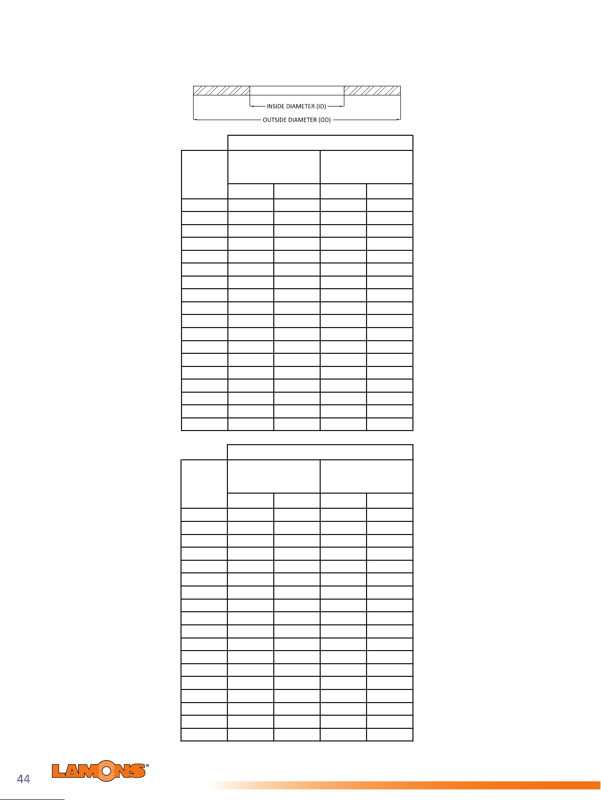
Dimensions for Ring Gaskets per ASME B16.21
to Suit ASME B16.47 Series A Flanges
Class 150
Nominal
Pipe Size
(NPS)
26 26.00 660 30.50 775
28 28.00 711 32.75 832
30 30.00 762 34.75 883
32 32.00 813 37.00 940
34 34.00 864 39.00 991
36 36.00 914 41.25 1048
38 38.00 965 43.75 1111
40 40.00 1016 45.75 1162
42 42.00 1067 48.00 1219
44 44.00 1118 50.25 1276
46 46.00 1168 52.25 1327
48 48.00 1219 54.50 1384
50 50.00 1270 56.50 1435
52 52.00 1321 58.75 1492
54 54.00 1372 61.00 1549
56 56.00 1422 63.25 1607
58 58.00 1473 65.50 1664
60 60.00 1524 67.50 1715
Inside Diameter
(ID)
Inches mm Inches mm
Class 300
Outside Di
(OD)
ameter
I
Nominal
Pipe Size
(NPS)
26 26.00 660 32.88 835
28 28.00 711 35.38 899
30 30.00 762 37.50 953
32 32.00 813 39.62 1006
34 34.00 864 41.62 1057
36 36.00 914 44.00 1118
38 38.00 965 41.50 1054
40 40.00 1016 43.88 1115
42 42.00 1067 45.88 1165
44 44.00 1118 48.00 1219
46 46.00 1168 50.12 1273
48 48.00 1219 52.12 1324
50 50.00 1270 54.25 1378
52 52.00 1321 56.25 1429
54 54.00 1372 58.75 1492
56 56.00 1422 60.75 1543
58 58.00 1473 62.75 1594
60 60.00 1524 64.75 1645
nside Diameter
(ID)
Inches mm Inches mm
Outside Diameter
(OD)
Sealing Global - Servicing Local

Sealing Global - Servicing Local
Dimensions for Ring Gaskets per ASME B16.21
to Suit ASME B16.47 Series A Flanges
Class 400
I
Nominal
Pipe Size
(NPS)
26 26.00 660 32.75 832
28 28.00 711 35.12 892
30 30.00 762 37.25 946
32 32.00 813 39.50 1003
34 34.00 864 41.50 1054
36 36.00 914 44.00 1118
38 38.00 965 42.25 1073
40 40.00 1016 44.38 1127
42 42.00 1067 46.38 1178
44 44.00 1118 48.50 1232
46 46.00 1168 50.75 1289
48 48.00 1219 53.00 1346
50 50.00 1270 55.25 1403
52 52.00 1321 57.26 1454
54 54.00 1372 59.75 1518
56 56.00 1422 61.75 1568
58 58.00 1473 63.75 1619
60 60.00 1524 66.25 1683
nside Diameter
(ID)
Inches mm Inches mm
Outside Diameter
(OD)
Class 600
I
Nominal
Pipe Size
(NPS)
26 26.00 660 34.12 867
28 28.00 711 36.00 914
30 30.00 762 38.25 972
32 32.00 813 40.25 1022
34 34.00 864 42.25 1073
36 36.00 914 44.50 1130
38 38.00 965 43.50 1105
40 40.00 1016 45.50 1156
42 42.00 1067 48.00 1219
44 44.00 1118 50.00 1270
46 46.00 1168 52.26 1327
48 48.00 1219 54.75 1391
50 50.00 1270 57.00 1448
52 52.00 1321 59.00 1499
54 54.00 1372 61.25 1556
56 56.00 1422 63.50 1613
58 58.00 1473 65.50 1664
60 60.00 1524 67.75 1721
nside Diameter
(ID)
Inches mm Inches mm
Outside Diameter
(OD)
45

Dimensions for Full Face Gaskets to Suit
Class 300
ASME B16.47 Series A Flanges
Class 150
Nominal
Pipe Size
(NPS)
26 26.00 660 34.25 870 24 1.38 31.75 806.5
28 28.00 711 36.50 927 28 1.38 34.00 863.6
30 30.00 762 38.75 984 28 1.38 36.00 914.4
32 32.00 813 41.75 1060 28 1.63 38.50 977.9
34 34.00 864 43.75 1111 32 1.63 40.50 1028.7
36 36.00 914 46.00 1168 32 1.63 42.75 1085.9
38 38.00 965 48.75 1238 32 1.63 45.25 1149.4
40 40.00 1016 50.75 1289 36 1.63 47.25 1200.2
42 42.00 1067 53.00 1346 36 1.63 49.50 1257.3
44 44.00 1118 55.25 1403 40 1.63 51.75 1314.5
46 46.00 1168 57.25 14
48 48.00 1219 59.50 1511 44 1.63 56.00 1422.4
50 50.00 1270 61.75 1568 44 1.88 58.25 1479.6
52 52.00 1321 64.00 1626 44 1.88 60.50 1536.7
54 54.00 1372 66.25 1683 44 1.88 62.75 1593.9
56 56.00 1422 68.75 1746 48 1.88 65.00 1651.0
58 58.00 1473 71.00 1803 48 1.88 67.25 1708.2
60 60.00 1524 73.00 1854 52 1.88 69.25 1759.0
Inside Diameter
(ID)
Inches mm Inches mm Inches mm
Outside Diameter
(OD)
54
# of Bolt
Holes
40 1.63 53.75 1365.3
Bolt Hole
Diameter
Bolt Circle Diamet
(BCD)
er
Nominal
Pipe Size
(NPS)
26 26.00 662 38.25 972 28 1.75 34.50 876.3
28 28.00 713 40.75 1035 28 1.75 37.00 939.8
30 30.00 764 43.00 1092 28 1.88 39.25 997.0
32 32.00 815 45.25 1149 28 2.00 41.50 1054.1
34 34.00 866 47.50 1207 28 2.00 43.50 1104.9
36 36.00 917 50.00 1270 32 2.13 46.00 1168.4
38 38.00 968 46.00 1168 32 1.63 43.00 1092.2
40 40.00 1019 48.75 1238 32 1.75 45.50 1155.7
42 42.00 1070 50.75 1289 32 1.75 47.50 1206.5
44 44.00 1121 53.25 1353 32 1.88 49.75 1263.7
46 46.00 1172 55.75 1
48 48.00 1223 57.75 1467 32 2.00 54.00 1371.6
50 50.00 1274 60.25 1530 32 2.13 56.25 1428.8
52 52.00 1324 62.25 1581 32 2.13 58.25 1479.6
54 54.00 1375 65.25 1657 28 2.38 61.00 1549.4
56 56.00 1426 67.25 1708 28 2.38 63.00 1600.2
58 58.00 1477 69.25 1759 32 2.38 65.00 1651.0
60 60.00 1528 71.25 1810 32 2.38 67.00 1701.8
Inside Diameter
(ID)
Inches mm Inches mm Inches mm
Outside Diameter
(OD)
416 28 2.00 52.00 1320.8
# of Bolt
Holes
Bolt Hole
Diameter
Bolt Circle Diameter
(BCD)
Sealing Global - Servicing Local
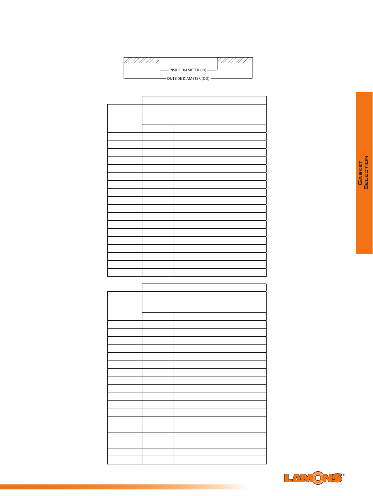
Sealing Global - Servicing Local
Dimensions for Ring Gaskets per ASME B16.21
Class 150
Class 300
to Suit ASME B16.47 Series B Flanges
Nominal
Pipe Size
(NPS)
26
28
30
32
34
36
38
40
42
44
46
48
50
52
54
56
58
60
Inside Diameter
(ID)
Outside Diameter
(OD)
Inches mm Inches mm
26.00 660 28.56 725
28.00 711 30.56 776
30.00 762 32.56 827
32.00 813 34.69 881
34.00 864 36.81 935
36.00 914 38.88 988
38.00 965 41.12 1044
40.00 1016 43.12 1095
42.00 1067 45.12 1146
44.00 1118 47.12 1197
46.00 1168 49.44 1256
48.00 1219 51.44 1307
50.00 1270 53.44 1357
52.00 1321 55.44 1408
54.00 1372 57.62 1464
56.00 1422 59.62 1514
58.00 1473 62.19 1580
60.00 1524 64.19 1630
Nominal
Pipe Size
(NPS)
26
28
30
32
34
36
38
40
42
44
46
48
50
52
54
56
58
60
Inside Diameter
(ID)
Outside Diameter
(OD)
Inches mm Inches mm
26.00 660 30.38 772
28.00 711 32.50 826
30.00 762 34.88 886
32.00 813 37.00 940
34.00 864 39.12 994
36.00 914 41.25 1048
38.00 965 43.25 1099
40.00 1016 45.25 1149
42.00 1067 47.25 1200
44.00 1118 49.25 1251
46.00 1168 51.88 1318
48.00 1219 53.88 1369
50.00 1270 55.88 1419
52.00 1321 57.88 1470
54.00 1372 60.25 1530
56.00 1422 62.75 1594
58.00 1473 65.19 1656
60.00 1524 67.12 1705
47
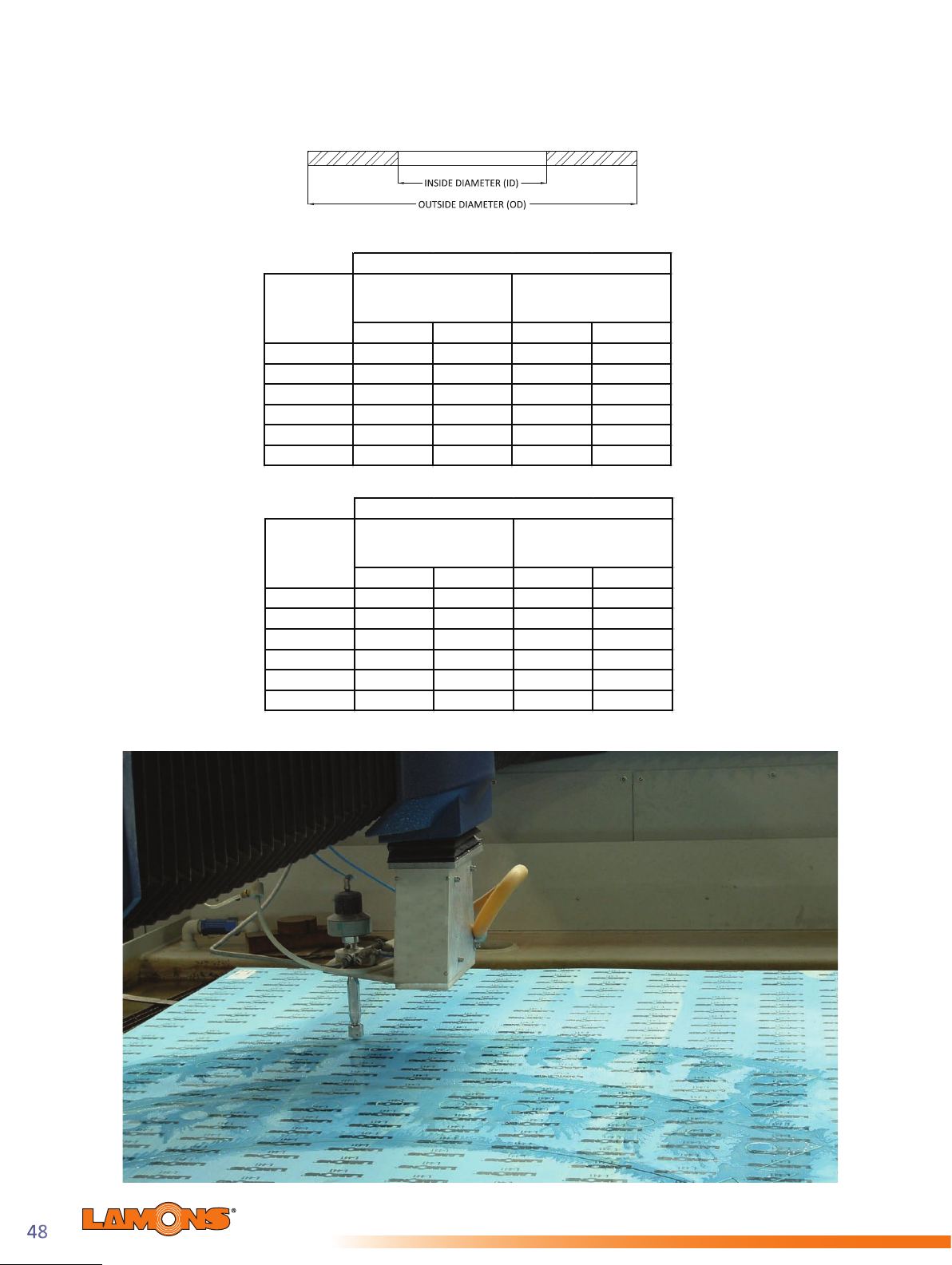
Dimensions for Flat Ring Gaskets per ASME B16.21
Class 400
to Suit ASME B16.47 Series B Flanges
Nominal
Pipe Size
(NPS)
26
28
30
32
34
36
Inside Diameter
(ID)
Inches mm Inches mm
26.00 660 29.38 746
28.00 711 31.50 800
30.00 762 33.75 857
32.00 813 35.88 911
34.00 864 37.88 962
36.00 914 40.25 1022
Outside Diameter
(OD)
Class 600
Nominal
Pipe Size
(NPS)
26 26.00 660 30.12 765
28 28.00 711 32.25 819
30 30.00 762 34.62 879
32 32.00 813 36.75 933
34 34.00 864 39.25 997
36 36.00 914 41.25 1048
Inside Diameter
(ID)
Inches mm Inches mm
Outside Diameter
(OD)
Sealing Global - Servicing Local

Sealing Global - Servicing Local
Dimensions for Full Face Gaskets to Suit
ASME B16.47 Series B Flanges
Class 150
Nominal
Pipe Size
(NPS)
Inside Diameter
(ID)
Inches mm Inches mm Inches mm
26 26.00 660 30.94 786 36 0.88 29.31 744.5
28 28.00 711 32.94 837 40 0.88 31.31 795.3
30 30.00 762 34.94 887 44 0.88 33.31 846.1
32 32.00 813 37.06 941 48 0.88 35.44 900.2
34 34.00 864 39.56 1005 40 1.00 37.69 957.3
36 36.00 914 41.63 1057 44 1.00 39.75 1009.7
38 38.00 965 44.25 1124 40 1.13 42.13 1070.1
40 40.00 1016 46.25 1175 44 1.13 44.13 1120.9
42 42.00 1067 48.25 1226 48 1.13 46.13 1171.7
44 44.00 1118 50.25 1276 52 1.13 48.13 1222.5
46 46.00 1168 52.81 1341 40
48 48.00 1219 54.81 1392 44 1.25 52.56 1335.0
50 50.00 1270 56.81 1443 48 1.25 54.56 1385.8
52 52.00 1321 58.81 1494 52 1.25 56.56 1436.6
54 54.00 1372 61.00 1549 56 1.25 58.75 1492.3
56 56.00 1422 63.00 1600 60 1.25 60.75 1543.1
58 58.00 1473 65.94 1675 48 1.38 63.44 1611.4
60 60.00 1524 67.94 1726 52 1.38 65.44 1662.2
Outside Diameter
(OD)
# of Bolt
Holes
Bolt Hole
Diameter
Bolt Circle Diameter
(BCD)
1.25 50.56 1284.2
Class 300
Nominal
Pipe Size
(NPS)
26 26.00 660 34.13 867 32 1.38 31.63 803.4
28 28.00 711 36.25 921 36 1.38 33.75 857.3
30 30.00 762 39.00 991 36 1.50 36.25 920.8
32 32.00 813 41.50 1054 32 1.63 38.50 977.9
34 34.00 864 43.63 1108 36 1.63 40.63 1032.0
36 36.00 914 46.13 1172 32 1.75 42.88 1089.2
38 38.00 965 48.13 1223 36 1.75 44.88 1140.0
40 40.00 1016 50.13 1273 40 1.75 46.88 1190.8
42 42.00 1067 52.50 1334 36 1.88 49.00 1244.6
44 44.00 1118 54.50 1384 40 1.88 51.00 1295.4
46 46.00 1168 57.50 1461
48 48.00 1219 59.50 1511 40 2.00 55.75 1416.1
50 50.00 1270 61.50 1562 44 2.00 57.75 1466.9
52 52.00 1321 63.50 1613 48 2.00 59.75 1517.7
54 54.00 1372 65.88 1673 48 2.00 62.13 1578.1
56 56.00 1422 69.50 1765 36 2.38 65.00 1651.0
58 58.00 1473 71.94 1827 40 2.38 67.44 1713.0
60 60.00 1524 73.94 1878 40 2.38 69.44 1763.8
Inside Diameter
(ID)
Inches mm Inches mm Inches mm
Outside Diameter
(OD)
# of Bolt
Holes
36 2.00 53.75 1365.3
Bolt Hole
Diameter
Bolt Circle Diameter
(BCD)
49
Section Two: Semi-Metallic Gaskets
Semi-Metallic gaskets are designed to feature soft, pliable sealing materials - which enhance the
tightness of the assembly with lower overall load requirements when compared to full metallic
gaskets. They are most popular due to this con guration, and are available in a wide variety
of styles and sizes. They can typically be fabricated of any metal which is available in thin strip
or sheet, and which can be welded. Therefore, they can be used against virtually any corrosive
medium dependent upon the choice of the metal and ller/facing material. Additionally, they
can be used over the complete temperature range from cryogenic to approximately 2000ºF
(1093ºC). Semi-metallic gaskets can generally be used in pressures ranging from vacuum to
those seen in ASME B16.5 standard 2500 pressure class ange ratings. They are resilient and,
as a consequence, can compensate somewhat for ange movement that may occur due to
temperature gradients, variations of pressure and vibration.
Lamons offers the following ller / facing materials for semi-metallic gaskets:
Temperature Range
PTFE Cryogenic to 500°F (260ºC)
Flexible Graphite Cryogenic to 850°F (454ºC)
Oxida on Resistant Grade Flexible Graphite Cryogenic to 975°F (524ºC)
HTG (High Temperature Gasket) Cryogenic to 1500°F (816ºC)
Mica Cryogenic to 1832°F (1000ºC)
Ceramic Cryogenic to 2000°F (1093ºC)
Sealing Global - Servicing Local
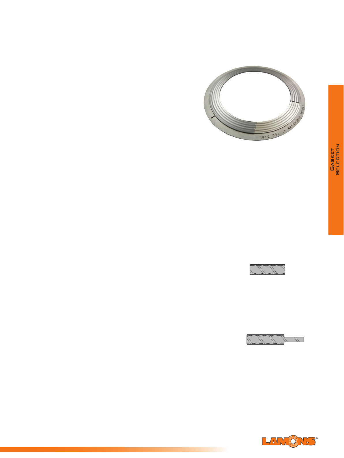
Sealing Global - Servicing Local
Lamons CorruKammTM Product Family
The Lamons CorruKammTM resembles a typical
kammproled sealing element in that it utilizes a heavy
substrate capable of extreme load bearing properties.
The dramatic feature that this design incorporates is
a precisely located corrugated pattern which greatly
enhances the ability to deect and compress under
load. This creates a scenario in which the gasket
will be more forgiving where perfect alignment and
parallelism do not exist.
The base core material is very thick and resembles
what is used with traditional kammprole technology.
This added substrate thickness, with an exacting
corrugated pattern allows the gasket to recover
substantially and maintain very stable load bearing
characteristics. A kammprole incorporates a specic
serration pattern on both sealing surfaces that do not relate in any way to the opposing sides.
The CorruKammTM technology utilizes a geometry on the sealing surface that is machined
rather than formed. These corrugation proles are strategically aligned so that deection can
occur and maximum resilience and recovery can be achieved.
Lamons CorruKammTM technology is a revolutionary new design that provides the benets
of a kammprole technology with the additional attribute of recovery that is desired to offset
ange relaxation and unloading. It combines the proven concepts of a kammprole and a
corrugated design.
The result eliminates many of the deciencies found in both designs while consolidating
the benets. A machined prole, not formed, allows for a correcting alternated geometry,
strategically indexed and aligned so that deection occurs. The result is maximum stability,
recovery, resiliency, deection and conformance.
CorruKammTM CK1
Lamons Corrugated Metal Gasket (CMG) is manufactured without
a guide ring for tongue and groove, or recessed ange applications
such as male and female. It is typically used in heat exchanger
applications and applied as an upgrade to double jacketed gaskets.
It is highly suggested to have the nubbin (if present) machined out as a best
practice. Where pass partitions are required, they are also kamm proled
and laminated. They are the same thickness as the ring, and securely held
in place with welds.
CorruKammTM CK2
Lamons CMG-EX gasket is constructed with an integral guide ring for
aligning purposes. It is suggested to be used in raised face anges. The
gasket is typically designed and sized per EN12560-6 spec for ASME B16.5
anges, but can be manufactured to t other standards.
51

CorruKamm
TM
HTG
Lamons CMG-PTFE gasket is a problem solver for higher operating
temperature scenarios. It utilizes sections of high performance mica/
phyllosilicate that protect oxidation resistant grade graphite and shields it
from contact with oxidizers. It represents the best technology available in
regards to torque retention and sealing ability at elevated temperatures.
Lamons CMG-PTFE gaskets can be applied to high temperature applications
to 1500°F (850°C) or higher, depending on operating conditions.
CorruKamm
TM
PTFE
Lamons CMG-EX gasket is a premium variation of Lamons original
CMG gasket. The CMG-EX was designed speci cally for heat exchanger
applications and provides superior performance in cyclic applications
and where a high level of radial shear is present. Differential movement
between anges can cause tremendous relaxation issues on traditional heat
exchanger gaskets. This problem is addressed in the design of the CMG-EX
gasket, as it maintains a highest degree of tightness through operation and
the full cycle event.
Sealing Global - Servicing Local

Sealing Global - Servicing Local
®
Lamons Kammpro
Gasket
Product Family
Lamons Kammpro gaskets are recognized
as a problem solver for heat exchangers,
large vessels, and equipment that experience
excessive movement due to thermal expansion.
The Kammpro provides one of the tightest
seals combined with superior load bearing
characteristics. Kammpro gaskets consist of a
metal sealing core with or without a guide ring.
The sealing core is a solid metal gasket with
concentric serrations on both sealing surfaces and
faced with a soft material such as exible graphite,
EPTFE, or a Lamons HTG conguration depending
on operating conditions. It is the preferred design
when needing improved performance at low
seating stresses. The simultaneous actions of a
high compressibility facing material on the outside
of the grooved metal in combination with limited
penetration of the tips of the solid metal core
enhance the interaction of the two materials. This
allows the components to perform individually
to their optimum capabilities. Kammpro gaskets
are manufactured in different materials and non-
circular shapes with extreme accuracy. They can also be custom engineered to t various
applications. The suggested ange surface nish for Kammpro gaskets is 125- 250 AARH.
Kammpro L P 1 is manufactured without a guide ring for tongue and groove,
or recessed ange applications such as male and female. It is typically used in heat
exchanger applications and applied as an upgrade to double jacketed gaskets.
It is highly suggested to have the nubbin (if present) machined out as a best practice. Where
pass partitions are required, they are also kamm proled and laminated. They are the same
thickness as the ring, and securely held in place with welds.
Kammpro LP2 is constructed with an integral guide ring
for aligning purposes. It is suggested to be used in raised face
anges. The gasket is typically designed and sized per EN12560-6
spec for ASME B16.5 anges, but can be manufactured to t other standards.
Kammpro LP3 utilizes a loose t guide ring. This popular
design is preferred for nominal pipe size and pressure class
raised face anges and is used in equipment with excessive
radial shear characteristics, thermal cycling, and expansions. The gasket is typically designed
and sized per EN12560-6 spec for ASME B16.5 anges, but can be manufactured to t other
standards.
Kammpro-HTG is a problem solver for higher operating
temperature scenarios. It utilizes sections of high performance
mica/phyllosilicate that protect oxidation resistant grade
graphite and shields it from contact with oxidizers. Lamons Kammpro-HTG represents
the best technology available in regards to torque retention and sealing ability at elevated
temperatures. Lamons Kammpro HTG gaskets can be applied to high temperature applications
to 1500°F (850°C) or higher, depending on operating conditions.
53

Kammpro ACHE (Fin Fan) gaskets are speci cally designed to replace
traditional solid metal “washer” type gaskets typically used in air cooled heat
exchangers. The design takes advantage of the serrated pro le with graphite facing
to bite against the nish of the header plate.
Kammpro Dual Seal gaskets are designed
to mate with leak detection devices incorporated
into anged assemblies used in critical applications,
such as lethal service. This highly effective gasket
has a primary seal followed towards the outer
portion of the sealing area by a relief section with
through holes, where the leak detection equipment
is mounted. Past this relief section is a secondary
sealing area that will maintain the integrity of the
bolted joint should the primary seal be compromised
and pressure differential is identi ed.
Dimensions for Kammpro LP3/LP2 per EN 12560 - 6
to Suit ASME B16.5 Flanges (Inches)
Guide Ring Outside Diameter (OD)
Nominal Pipe
Size (NPS)
1/2 0.91 1.31 1.75 2.00 2.00 2.00 2.37 2.37 2.63
3/4 1.13 1.56 2.12 2.50 2.50 2.50 2.63 2.63 2.87
1 1.44 1.87 2.50 2.75 2.75 2.75 3.00 3.00 3.25
1 1/4 1.75 2.37 2.87 3.13 3.13 3.13 3.37 3.37 4.00
1 1/2 2.06 2.75 3.25 3.63 3.63 3.63 3.75 3.75 4.50
2 2.75 3.
2 1/2 3.25 4.00 4.75 5.00 5.00 5.00 6.37 6.37 6.50
3 3.87 4.87 5.25 5.75 5.75 5.75 6.50 6.75 7.63
3 1/2 4.37 5.37 6.25 6.37 6.25 6.25 - - 4 4.87 6.06 6.75 7.00 6.87 7.50 8.00 8.13 9.12
5 5.94 7.19 7.63 8.37 8.25 9.37 9.63 9.87 10.87
6 7.00 8.37 8.63 9.75 9.63 10.37 11.25 11.00 12.37
8 9.00 10.50 10.87 12.00 11.87 12.50 14.00 9.81 15.12
10 11.13 12.63 13.25 14.13 14.00 15.63 17.00 17.00 18.62
12 13.37 14.87 16.00 16.50 16.37 17.87 19.50 20.37 21.50
14 14.6
16 16.63 18.37 20.13 21.13 21.00 22.12 22.50 25.12 18 18.87 20.87 21.50 23.37 23.25 24.00 25.00 27.63 20 20.87 22.87 23.75 25.63 25.37 26.75 27.37 29.62 22 22.87 24.87 25.87 27.63 27.50 28.75 - 24 24.87 26.87 28.13 30.37 30.13 31.00 32.87 35.37 -
Core Inside
Diameter (ID)
Inches Inches Inches Inches Inches Inches Inches Inches Inches
3 1
Core Outside
Diameter (OD)
50
6.13 17.63 19.00 18.87 19.25 20.37 22.63 -
Class 150 Class 300 Class 400 Class 600 Class 900 Class 1500 Class 2500
4.00 4.25 4.25 4.25 5.50 5.50 5.62
Sealing Global - Servicing Local

Sealing Global - Servicing Local
Dimensions for Kammpro LP3/LP2 per EN 12560-6
to Suit ASME B16.5 Flanges (Millimeters)
Guide Ring Outside Diameter (OD)
Nominal Pipe
Size (NPS)
1/2 23.0 33.3 44.4 50.8 50.8 50.8 60.3 60.3 66.7
3/4 28.6 39.7 53.9 63.5 63.5 63.5 66.7 66.7 73.0
1 36.5 47.6 63.5 69.8 69.8 69.8 76.2 76.2 82.5
1 1/4 44.4 60.3 73.0 79.4 79.4 79.4 85.7 85.7 101.6
1 1/2 52.4 69.8 82.5 92.1 92.1 92.1 95.2 95.2 114.3
2 69.8 88.9 101.6 108.0 108.0 108.0 139.7 139.7 142.
2 1/2 82.5 101.6 120.6 127.0 127.0 127.0 161.9 161.9 165.1
3 98.4 123.8 133.4 146.1 146.1 146.1 165.1 171.5 193.7
3 1/2 111.1 136.5 158.8 161.9 158.7 158.7 - - 4 123.8 154.0 171.5 177.8 174.6 190.5 203.2 206.4 231.7
5 150.8 182.6 193.7 212.7 209.5 238.1 244.5 250.8 276.2
6 177.8 212.7 219.1 247.7 244.5 263.5 285.8 279.4 314.3
8 228.6 266.7 276.2 304.8 301.6 317.5 355.6 249.3 384.1
10 282.6 320.7 336.5 358.8 355.6 396.9 431.8 431.8 473.0
12 339.7 377.8 406.4 419.1 415.9 454.0 495.
14 371.5 409.6 447.7 482.6 479.4 488.9 517.5 574.7 16 422.3 466.7 511.2 536.6 533.4 561.9 571.5 638.1 18 479.4 530.2 546.1 593.7 590.5 609.6 635.0 701.7 20 530.2 581.0 603.2 650.9 644.5 679.5 695.3 752.4 22 581.0 631.8 657.2 701.7 698.5 730.3 - - 24 631.8 682.6 714.4 771.5 765.2 787.4 835.0 898.5 -
Core Inside
Diameter (ID)
mm mm mm mm mm mm mm mm mm
Core Outside
Diameter (OD)
Class 150 Class 300 Class 400 Class 600 Class 900 Class 1500 Class 2500
3 517.5 546.1
8
55

Dimensions for Kammpro LP3/LP2 per ASME B16.20 2012 to
Suit B16.5 Flanges (Inches)
Guide Ring Outside Diameter (OD)
Nominal Pipe
Size (NPS)
1/2 0.91 1.31
3/4 1.13 1.56 2.25 2.63 2.63 2.63 2.75 2.75 3.00
1 1.44 1.87 2.63 2.88 2.88 2.88 3.13 3.13 3.38
1 1/4 1.75 2.37 3.00 3.25 3.25 3.25 3.50 3.50 4.13
1 1/2 2.06 2.75 3.38 3.75 3.75 3.75 3.88 3.88 4.63
2 2.75 3.50 4.13 4.38 4.38 4.38 5.63 5.63 5.75
2 1/2 3.25 4.00 4.88 5.13 5.13 5.13 6.50 6.50 6.63
3 3.87 4.87 5.38 5.88 5.88 5.88 6.63 6.88 7.75
4 4.87 6.06 6.88 7.13 7.00 7.63 8.13 8.25 9.25
5 5.94 7.19 7.75 8.50 8.38 9.50 9.75 10.00 11.00
6 7.00 8.37 8.75 9.88 9.75 10.50 11.38 11.13 12.50
8 9.00 10.50 11.00 12.13 12.00 12.63 14.13 13.88 15.25
10 11.13 12.63 13.38 14.25 14.13 15.75 17.13 17.13 18.75
12 13.37 14.87 16.13 16.63 16.50 18.00 19.63 20.50 21.63
14 14.63 16.13 17.75 19.31 19.00 19.38 20.50 22.75 -
16 16.63 18.37 20.25 21.25 21.13 22.25 22.63 25.25 -
18 18.87 20.87 21.63 23.50 23.38 24.13 25.13 27.75 -
20 20.87 22.87 23.88 25.75 25.50 26.88 27.50 29.75 -
24 24.87 26.87 28.25 30.50 30.25 31.13 33.00 35.50 N/A
Core Inside
Diameter (ID)
Core Outside
Diameter (OD)
Class 150 Class 300 Class 400 Class 600 Class 900 Class 1500 Class 2500
1.88 2.13 2.13 2.13 2.50 2.50 2.75
Sealing Global - Servicing Local
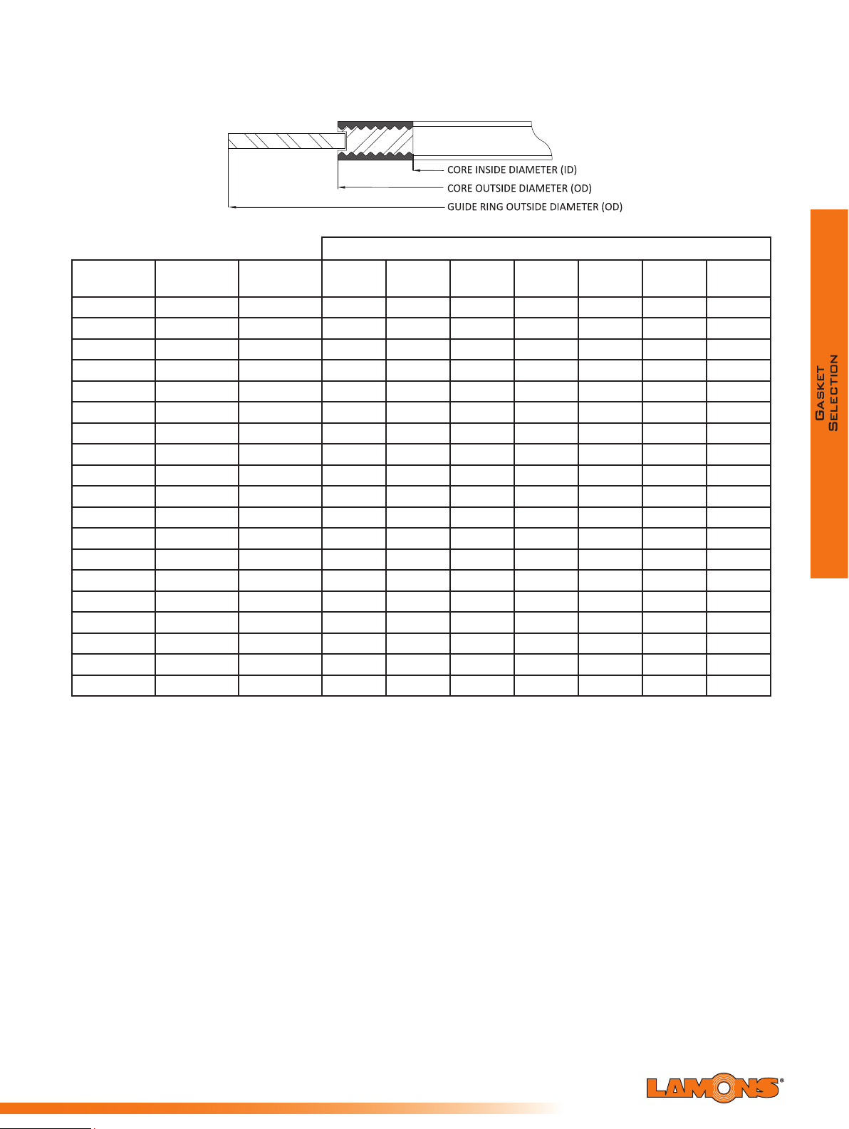
Sealing Global - Servicing Local
Dimensions for Kammpro LP3/LP2 per ASME B16.20 2012 to
Suit B16.5 Flanges (millimeters)
Guide Ring Outside Diameter (OD)
Nominal Pipe
Size (NPS)
1/2 23.1 33.3 47.8 54.1 54.1 54.1 63.5 63.5 69.9
3/4
1
1 1/4
1 1/2
2
2 1/2
3
4
5
6
8
10
12
14
16
18
20
24
Core Inside
Diameter (ID)
28.7 39.6 57.2 66.8 66.8 66.8 69.9 69.9 76.2
36.6 47.5 66.8 73.2 73.2 73.2 79.5 79.5 85.9
44.5 60.2 76.2 82.6 82.6 82.6 88.9 88.9 104.9
52.3 69.9 85.9 95.3 95.3 95.3 98.6 98.6 117.6
69.9 88.9 104.9 111.3 111.3 111.3 143.0 143.0 146.1
82.6 101.6 124.0 130.3 130.3 130.3 165.1 165.1 168.4
98.3 123.7 136.7 149.4 149.4 149.4 168.4 174.8 196.9
123.7 153.9 174.8 181.1 177.8 193.8 206.5 209.6 235.0
150.9 182.6 196.9 215.9 212.9 241.3 247.7 254.0 279.4
177.8 212.6 222.3 251.0 247.7 266.7 289.1 282.7 317.5
228.6 266.7 279.4 308.1 304.8 320.8 358.9 352.6 387.4
282.7 320.8 339.9 362.0 358.9 400.1 435.1 435.1 476.3
339.6 377.7 409.7 422.4 419.1 457.2 498.6 520.7 549.4
371.6 409.7 450.9 485.9 482.6 492.3 520.7 577.9
422.4 466.6 514.4 539.8 536.7 565.2 574.8 641.4
479.3 530.1 549.4 596.9 593.9 612.9 638.3 704.9
530.1 580.9 606.6 654.1 647.7 682.8 698.5 755.7
631.7 682.5 717.6 774.7 768.4 790.7 838.2 901.7
Core Outside
Diameter (OD)
Class 150 Class 300 Class 400 Class 600 Class 900 Class 1500 Class 2500
-
-
-
-
N/A
57

Dimensions for Kammpro LP3/LP2 per ASME B16.47 Series A
Centering
Centering
Centering
Centering
Centering
to Suit B16.47 Series A (Inches)
Class 150 Class 300
Grooved Core
Inside
NPS
Diameter
26 26.50 27.75 30.50 27.00 29.00 32.88 27.00 29.00 32.75 27.00 29.00 34.13 27.00 29.00 34.75
28 28.50 29.75 32.75 29.00 31.00 35.38 29.00 31.00 35.13 29.00 31.00 36.00 29.00 31.00 37.25
30 30.50 31.75 34.75 31.25 33.25 37.50 31.25 33.25 37.25 31.25 33.25 38.25 31.25 33.25 39.75
32 32.50 33.88 37.00 33.50 35.50 39.63 33.50 35.50 39.50 33.50 35.50 40.25 33.50 35.50 42.25
34 34.50 35.88 39.00 35.50 37.50 41.63 35.50 37.50 41.50 35.50 37.50 42.25 35.50 37.50 44.75
36 36.50 38.13 41.25 37.63 39.63 44.00 37.63 39.63 44.00 37.63 39.63 44.50 37.75 39.75 47.25
38 38.50 40.13 43.75 38.50 40.00 41.50 38.25 40.25 42.25 39.00 41.00 43.50 40.75 42.75 47.25
40 40.50 42.13 45.75 40.25 42.13 43.88 40.38 42.38 44.38 41.25 43.25 45.50 43.25 45.25 49.25
42 42.50 44.25 48.00 42.25 44.13 45.88 42.38 44.38 46.38 43.50 45.50 48.00 45.25 47.25 51.25
44 44.50 46.38 50.25 44.50 46.50 48.00 44.50 46.50 48.50 45.75 47.75 50.00 47.50 49.50 53.88
46 46.50 48.38 52.25 46.38 48.38 50.13 47.00 49.00 50.75 47.75 49.75 52.25 50.00 52.00 56.50
48 48.50 50.38 54.50 48.63 50.63 52.13 49.00 51.00 53.00 50.00 52.00 54.75 52.00 54.00 58.50
50 50.50 52.50 56.50 51.00 53.00 54.25 51.00 53.00 55.25 52.00 54.00 57.00 -- -- --
52 52.50 54.50 58.75 53.00 55.00 56.25 53.00 55.00 57.25 54.00 56.00 59.00 -- -- --
54 54.50 56.50 61.00 55.25 57.25 58.75 55.25 57.25 59.75 56.25 58.25 61.25 -- -- --
56 56.50 63.25 63.25 57.25 59.25 60.75 57.25 59.25 61.75 58.25 60.25 63.50 -- -- --
58 58.50 65.50 65.50 59.50 61.50 62.75 59.25 61.25 63.75 60.50 62.50 65.50 -- -- --
60 60.50 67.50 67.50 61.50 63.50 64.75 61.75 63.75 66.25 62.75 64.75 68.25 -- -- --
Outside
Diameter
Ring
Outside
Diameter
Grooved Core
Inside
Diameter
Outside
Diameter
Ring
Outside
Diameter
Diameter
Grooved Core
Inside
Class 400
Outside
Diameter
Ring
Outside
Diameter
Grooved Core
Inside
Diameter
Class 600
Outside
Diameter
Ring
Outside
Diameter
Grooved Core
Inside
Diameter
Class 900
Outside
Diameter
Ring
Outside
Diameter
Sealing Global - Servicing Local
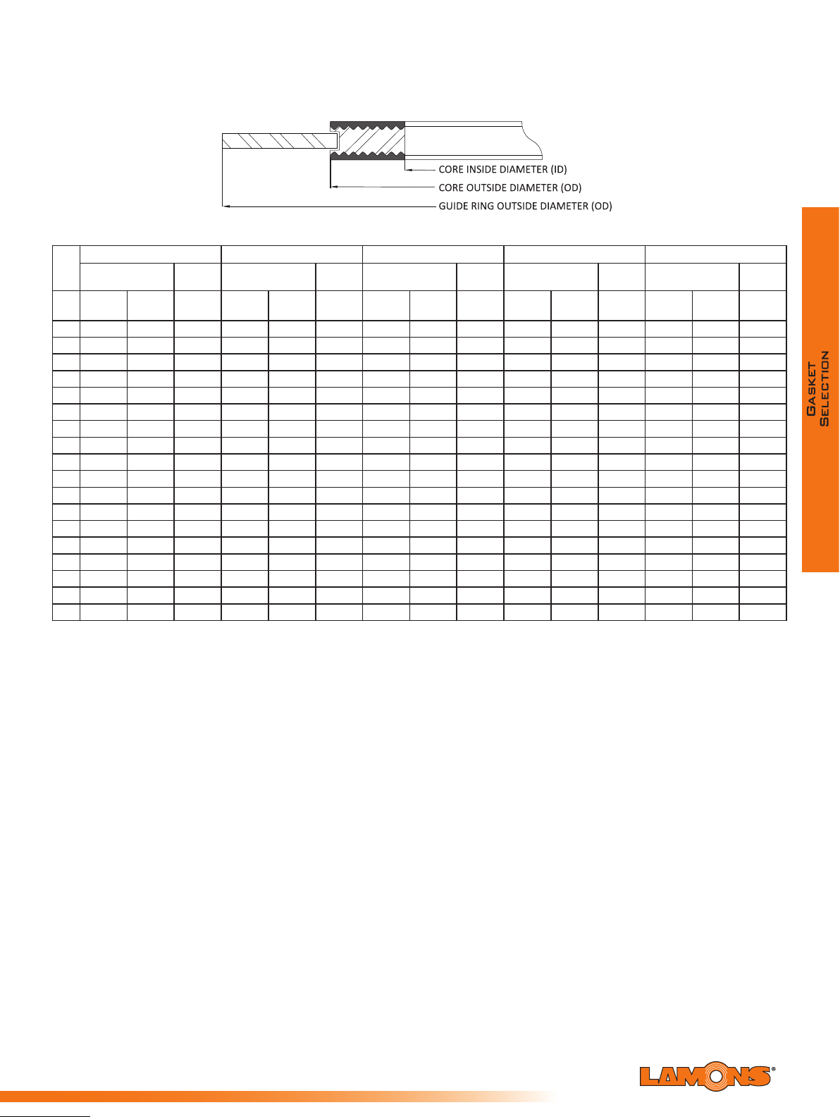
Sealing Global - Servicing Local
Dimensions for Kammpro LP3/LP2 per ASME B16.47 Series A
Centering
Ring
Centering
Ring
Centering
Ring
Centering
Ring
Centering
Ring
to Suit B16.47 Series A (Millimeters)
Class 150 Class 300
Grooved Core
Inside
NPS
Diameter
26 673.1 704.9 774.7 685.8 736.6 835.2 685.8 736.6 831.9 685.8 736.6 866.9 685.8 736.6 882.7
28 723.9 755.7 831.9 736.6 787.4 898.7 736.6 787.4 892.3 736.6 787.4 914.4 736.6 787.4 946.2
30 774.7 806.5 882.7 793.8 844.6 952.5 793.8 844.6 946.2 793.8 844.6 971.6 793.8 844.6 1009.7
32 825.5 860.6 939.8 850.9 901.7 1006.6 850.9 901.7 1003.3 850.9 901.7 1022.4 850.9 901.7 1073.2
34 876.3 911.4 990.6 901.7 952.5 1057.4 901.7 952.5 1054.1 901.7 952.5 1073.2 901.7 952.5 1136.7
36 927.1 968.5 1047.8 955.8 1006.6 1117.6 955.8 1006.6 1117.6 955.8 1006.6 1130.3 958.9 1009.7 1200.2
38 977.9 1019.3 1111.3 977.9 1016.0 1054.1 971.6 1022.4 1073.2 990.6 1041.4 1104.9 1035.1 1085.9 1200.2
40 1028.7 1070.1 1162.1 1022.4 1070.1 1114.6 1025.7 1076.5 1127.3 1047.8 1098.6 1155.7 1098.6 1149.4 1251.0
42 1079.5 1124.0 1219.2 1073.2 1120.9 1165.4 1076.5 1127.3 1178.1 1104.9 1155.7 1219.2 1149.4 1200.2 1301.8
44 1130.3 1178.1 1276.4 1130.3 1181.1 1219.2 1130.3 1181.1 1231.9 1162.1 1212.9 1270.0 1206.5 1257.3 1368.6
46 1181.1 1228.9 1327.2 1178.1 1228.9 1273.3 1193.8 1244.6 1289.1 1212.9 1263.7 1327.2 1270.0 1320.8 1435.1
48 1231.9 1279.7 1384.3 1235.2 1286.0 1324.1 1244.6 1295.4 1346.2 1270.0 1320.8 1390.7 1320.8 1371.6 1485.9
50 1282.7 1333.5 1435.1 1295.4 1346.2 1378.0 1295.4 1346.2 1403.4 1320.8 1371.6 1447.8 -- -- --
52 1333.5 1384.3 1492.3 1346.2 1397.0 1428.8 1346.2 1397.0 1454.2 1371.6 1422.4 1498.6 -- -- --
54 1384.3 1435.1 1549.4 1403.4 1454.2 1492.3 1403.4 1454.2 1517.7 1428.8 1479.6 1555.8 -- -- --
56 1435.1 1485.9 1606.6 1454.2 1505.0 1543.1 1454.2 1505.0 1568.5 1479.6 1530.4 1612.9 -- -- --
58 1485.9 1536.7 1663.7 1511.3 1562.1 1593.9 1505.0 1555.8 1619.3 1536.7
60 1536.7 1587.5 1714.5 1562.1 1612.9 1644.7 1568.5 1619.3 1682.8 1593.9 1644.7 1733.6 -- -- --
Outside
Diameter
Outside
Diameter
Grooved Core
Inside
Diameter
Outside
Diameter
Outside
Diameter
Diameter
Grooved Core
Inside
Class 400
Outside
Diameter
Outside
Diameter
Grooved Core
Inside
Diameter
Class 600
Outside
Diameter
1587.5
Class 900
Grooved Core
Outside
Diameter
1663.7 -- -- --
Inside
Diameter
Outside
Diameter
Outside
Diameter
59

Dimensions for Kammpro LP3/LP2 per ASME B16.47 Series B
Centering
Centering
Centering
Centering
Centering
to Suit B16.47 Series B (Inches)
Class 150 Class 300
Grooved Core
Inside
NPS
Diameter
26 26.50 27.50 28.56 26.50 28.00 30.38 26.25 27.50 29.38 26.13 28.13 30.13 27.25 29.50 33.00
28 28.50 29.50 30.56 28.50 30.00 32.50 28.13 29.50 31.50 27.75 29.75 32.25 29.25 31.50 35.50
30 30.50 31.50 32.56 30.50 32.00 34.88 30.13 31.75 33.75 30.63 32.63 34.63 31.75 33.75 37.75
32 32.50 33.50 34.69 32.50 34.00 37.00 32.00 33.88 35.88 32.75 34.75 36.75 34.00 36.00 40.00
34 34.50 35.75 36.81 34.50 36.00 39.13 34.13 35.88 37.88 35.00 37.00 39.25 36.25 38.25 42.25
36 36.50 37.75 38.88 36.50 38.00 41.25 36.13 38.00 40.25 37.00 39.00 41.25 37.25 39.25 44.25
38 38.38 39.75 41.13 39.75 41.25 43.25 38.25 40.25 42.25 39.00 41.00 43.50 40.75 42.75 47.25
40 40.25 41.88 43.13 41.75 43.25 45.25 40.38 42.38 44.38 41.25 43.25 45.50 43.25 45.25 49.25
42 42.50 43.88 45.13 43.75 45.25 47.25 42.38 44.38 46.38 43.50 45.50 48.00 45.25 47.25 51.25
44 44.25 45.88 47.13 45.75 47.25 49.25 44.50 46.50 48.50 45.75 47.75 50.00 47.50 49.50 53.88
46 46.50 48.19 49.44 47.88 49.38 51.88 47.00 49.00 50.75 47.75 49.75 52.25 50.00 52.00 56.50
48 48.50 50.00 51.44 49.75 51.63 53.88 49.00 51.00 53.00 50.00 52.00 54.75 52.00 54.00 58.50
50 50.50 52.19 53.44 51.88 53.38 55.88 51.00 53.00 55.25 52.00 54.00 57.00 -- -- --
52 52.50 54.19 55.44 53.88 55.38 57.88 53.00 55.00 57.25 54.00 56.00 59.00 -- -- --
54 54.50 56.00 57.63 55.25 57.25 60.25 55.25 57.25 59.75 56.25 58.25 61.25 -- -- --
56 56.88 58.19 59.63 58.25 60.00 62.75 57.25 59.25 61.75 58.25 60.25 63.50 -- -- --
58 59.08 60.19 62.19 60.44 61.94 65.19 59.25 61.25 63.75 60.50 62.50 65.50 -- -- --
60 61.31 62.44 64.19 62.56 64.19 67.19 61.75 63.75 66.25 62.75 64.75 68.25 -- -- --
Outside
Diameter
Ring
Outside
Diameter
Grooved Core
Inside
Diameter
Outside
Diameter
Ring
Outside
Diameter
Diameter
Grooved Core
Inside
Class 400
Outside
Diameter
Ring
Outside
Diameter
Grooved Core
Inside
Diameter
Class 600
Outside
Diameter
Ring
Outside
Diameter
Grooved Core
Inside
Diameter
Class 900
Outside
Diameter
Ring
Outside
Diameter
Sealing Global - Servicing Local

Sealing Global - Servicing Local
Dimensions for Kammpro LP3/LP2 per ASME B16.47 Series B
to Suit B16.47 Series B (Millimeters)
Grooved Core
Inside
Class 400
Outside
Diameter
Centering
Ring
Outside
Diameter
Diameter
Class 150 Class 300
Centering
Ring
Inside
NPS
Diameter
26 673.1 698.5 725.4 673.1 711.2 771.7 666.8 698.5 746.3 663.7 714.5 765.3 692.2 749.3 838.2
28 723.9 749.3 776.2 723.9 762.0 825.5 714.5 749.3 800.1 704.9 755.7 819.2 743.0 800.1 901.7
30 774.7 800.1 827.0 774.7 812.8 886.0 765.3 806.5 857.3 778.0 828.8 879.6 806.5 857.3 958.9
32 825.5 850.9 881.1 825.5 863.6 939.8 812.8 860.6 911.4 831.9 882.7 933.5 863.6 914.4 1016.0
34 876.3 908.1 935.0 876.3 914.4 993.9 866.9 911.4 962.2 889.0 939.8 997.0 920.8 971.6 1073.2
36 927.1 958.9 987.6 927.1 965.2 1047.8 917.7 965.2 1022.4 939.8 990.6 1047.8 946.2 997.6 1124.0
38 974.9 1009.7 1044.7 1009.7 1047.8 1098.6 971.6 1022.4 1073.2 990.6 1041.4 1104.9 1035.1 1085.9 1200.2
40 1022.4 1063.8 1095.5 1060.5 1098.6 1149.4 1025.7 1076.5 1127.3 1047.8 1098.6 1155.7 1098.6 1149.4 1251.0
42 1079.5 1114.6 1146.3 1111.3 1149.4 1200.2 1076.5 1127.3 1178.1 1104.9 1155.7 1219.2 1149.4 1200.2 1301.8
44 1124.0 1165.4 1197.1 1162.1 1200.2 1251.0 1130.3 1181.1 1231.9 1162.1 1212.9 1270.0 1206.5 1257.3 1368.6
46 1181.1 1224.0 1255.8 1216.2 1254.3 1317.8 1193.8 1244.6 1289.1 1212.9 1263.7 1327.2 1270.0 1320.8 1435.1
48 1231.9 1270.0 1306.6 1263.7 1311.4 1368.6 1244.6 1295.4 1346.2 1270.0 1320.8 1390.7 1320.8 1371.6 1485.9
50 1282.7 1325.6 1357.4 1317.8 1355.9 1419.4 1295.4 1346.2 1403.4 1320.8 1371.6 1447.8 -- -- --
52 1333.5 1376.4
54 1384.3 1422.4 1463.8 1403.4 1454.2 1530.4 1403.4 1454.2 1517.7 1428.8 1479.6 1555.8 -- -- --
56 1444.8 1478.0 1514.6 1479.6 1524.0 1593.9 1454.2 1505.0 1568.5 1479.6 1530.4 1612.9 -- -- --
58 1500.6 1528.8 1579.6 1535.2 1573.3 1655.8 1505.0 1555.8 1619.3 1536.7 1587.5 1663.7 -- -- --
60 1557.3 1586.0 1630.4 1589.0 1630.4 1706.6 1568.5 1619.3 1682.8 1593.9 1644.7 1733.6 -- -- --
Outside
Diameter
Outside
Diameter
1408.2
Grooved Core
Inside
Diameter
Outside
Diameter
1368.6 1406.7 1470.2 1346.2 1397.0 1454.2 1371.6 1422.4 1498.6 -- -- --
Centering
Ring
Outside
Diameter
Diameter
Grooved Core
Inside
Class 600
Outside
Diameter
Centering
Ring
Outside
Diameter
Grooved CoreGrooved Core
Inside
Diameter
Class 900
Outside
Diameter
Centering
Ring
Outside
Diameter
61

Dimensions for Kammpro LP3/LP2 per EN 1514 - 6 to
mm Inches
10 0.87 1.42 1.81 1.81 1.81 1.81 2.20 2.20 2.20 2.64 2.64 2.64
1.02 1.65 2.01 2.01 2.01 2.01 2.40 2.40 2.40 2.83 2.83 --
20
15
1.22 1.85 2.40 2.40 2.40 2.40 -- -- -- -- -- -25 1.42 2.05 2.80 2.80 2.80 2.80 3.23 3.23 3.23 3.27 3.62 4.09
32 1.81 2.44 2.60 3.23 3.23 3.23 3.23 -- -- -- -- -- -40 2.09 2.72 2.87 3.62 3.62 3.62 3.62 4.06 4.06 4.06 4.29 4.69 5.31
50 2.56 3.19 3.43 4.21 4.21 4.21 4.21 4.45 4.69 4.69 4.88 5.28 5.91
65 3.19 3.94 4.06 5.00 5.00 5.00 5.00 5.39 5.63 5.63 6.02 6.69 7.56
8
0 3.74 4.53 4.76 5.59 5.59 5.59 5.59 5.83 6.06 6.06 6.69 7.48 8.15
100 4.65 5.43 5.75 6.38 6.38 6.61 6.61 6.85 7.09 7.09 7.95 9.02 10.08
125 5.59 6.38 7.01 7.56 7.56 7.64 7.64 8.27 8.54 8.54 9.53 10.79 11.85
150 6.69 7.48 8.35 8.54 8.54 8.82 8.82 9.72 10.12 10.12 11.18 12.24 13.70
175 7.68 8.46 9.65 9.72 9.72 10.00 10.43 10.91 11.30 11.18 12.44 14.09 15.83
200 8.66 9.45 9.76 11.02 10.71 10.71 11.18 11.42 12.17 12.76 12.76 14.09 15.67 17.40
250 10.63 11.42 11.81 13.39 12.87 12.91 13.39 13.
86 14.33 15.39 15.28 17.40 19.21 -300 12.60 13.39 14.02 15.75 14.84 15.08 15.75 16.42 16.69 18.03 18.03 21.10 -- -350 14.76 15.55 16.34 -- 17.20 17.44 17.99 18.66 19.13 20.16 -- -- -- -400 16.77 17.72 18.66 -- 19.25 19.49 20.24 21.50 21.38 22.52 -- -- -- -450 18.90 19.92 -- -- 21.22 21.85 -- 22.48 -- -- -- -- -- -500 20.87 22.05 23.15 -- 23.39 24.29 24.57 24.72 25.87 27.72 -- -- -- -600 24.80 26.14 27.56 -- 27.36 28.90 28.78 29.41 30.08 32.01 -- -- -- -700 28.74 30.31 31.97 -- 31.89 3
1.65 32.80 33.54 34.61 37.40 -- -- -- -800 32.68 34.49 34.88 -- 36.10 35.87 37.09 38.35 38.90 -- -- -- -- -900 36.61 38.66 39.13 -- 40.04 39.80 41.02 42.68 43.62 -- -- -- -- --
1000 40.94 43.23 43.70 -- 44.25 44.41 45.43 47.01 48.03 -- -- -- -- -1200 49.21 51.97 52.52 -- 52.80 52.83 53.70 55.04 57.17 -- -- -- -- -1400 56.69 59.92 -- -- 60.94 60.71 62.13 63.70 -- -- -- -- -- -1600 64.96 6.77 -- -- 69.76 69.45 70.79 72.05 -- -- -- -- -- -1800 72.83 75.35 -- -- 77.64 77.32 78.74 -- -- -- -- -- -- -2000 80.71 83.46 -- -- 85.91 85.35 87.80 -- -- -- -- -- -- -2200 88.58 91.65 -- -- 93.86 93.62 -- -- -- -- -- -- -- -2400 96.85 98.90 -- -- 102.13 -- -- -- -- -- -- -- -- -2600 105.12 107.40 -- -- 110.00 -- -- -- -- -- -- -- -- -2800 113.78 116.22 -- -- 118.66 -- -- -- -- -- -- -- -- -3000 122.05 124.65 -- -- 127.09 -- -- -- -- -- -- -- -- --
See PN 64 to
PN 160
See PN 250
to PN 400
PN 40 PN 64
Inches
PN 250 PN 320 PN 400PN 100 PN 160
Inches
DN
Core
Inside
Diameter
Core Outside Diameter (OD)
PN10/40 PN 64/160 PN 250/400 PN 25
Guide Ring Outside Diameter (OD)
PN 10 PN 16
Suit Type A and B Flanges Facings (Inches)
Sealing Global - Servicing Local

Sealing Global - Servicing Local
Dimensions for Kammpro LP3/LP2 per EN 1514 - 6 to
mm
mm
Suit Type A and B Flanges Facings (Millimeters)
Core Inside
DN
Diameter
(ID)
mm mm
10 22 36 46 46 46 46 56 56 56 67 67 67
15 26 42 51 51 51 51 61 61 61 72 72 -20 31 47 61 61 61 61 -- -- -- -- -- -25 36 52 71 71 71 71 82 82 82 83 92 104
32 46 62 66 82 82 82 82 -- -- -- -- -- -40 53 69 73 92 92 92 92 103 103 103 109 119 135
50 65 81 87 107 107 107 107 113 119 119 124 134 150
65 81 100 103 127 127 127 127 137 143 143 153 170 192
80 95 115 121 142 142 142 142 148 154 154 170 190 207
100 118 138 146 162 162 168 168 174 180 180 202 22 9 256
125 142 162 178 192 192 194 194 210 217 217 242 27 4 301
150 170 190 212 217 217 224 224 247
175 195 215 245 247 247 254 265 277 287 284 316 35 8 402
200 220 240 248 280 272 272 284 290 309 324 324 358 398 442
250 270 290 300 340 327 328 340 352 364 391 388 442 488 -300 320 340 356 400 377 383 400 417 424 458 458 536 -- -350 375 395 415 -- 437 443 457 474 486 512 -- -- -- -400 426 450 474 -- 489 495 514 546 543 572 -- -- -- -450 480 506 -- -- 539 555 -- 571 -- -- -- -- -- -500 530 560 588 -- 594 617 624 628 657 704 -- -- -- -600 630 664 700 -- 695 734 731 747 764 813 -- -- -- -700 730 770 812 -- 8
800 830 876 886 -- 917 911 942 974 988 -- -- -- -- -900 930 982 994 -- 1017 1011 1042 1084 1108 -- -- -- -- --
1000 1040 1098 1110 -- 1124 1128 1154 1194 1220 -- -- -- -- -1200 1250 1320 1334 -- 1341 1342 1364 1398 1452 -- -- -- -- -1400 1440 1522 -- -- 1548 1542 1578 1618 -- -- -- -- -- -1600 1650 172 -- -- 1772 1764 1798 1830 -- -- -- -- -- -1800 1850 1914 -- -- 1972 1964 2000 -- -- -- -- -- -- -2000 2050 2120 -- -- 2182 2168 2230 -- -- -- -- -- -- --
2200 2250 2328 -- -- 2384 2378 2400 2460 2512 -- -- 2594 -- -- -- -- -- -- -- -- -2600 2670 2728 -- -- 2794 -- -- -- -- -- -- -- -- --
2800 2890 2952 -- -- 3014 -- -- -- -- -- -- -- -- --
3000 3100 3166 -- -- 3228 -- -- -- -- -- -- -- -- --
Core Outside Diameter (OD) Guide Ring Outside Diameter (OD)
See PN 64 to
PN 160
PN 64/160 PN 250/400 PN 400
See PN 250
to PN 400
PN 10 PN 16 PN 25 PN 160PN 10/40
10 804 833 852 879 950 -- -- -- --
PN 40 PN 64
- -- -- -- -- -- -- --
PN 100
257 257 284 311 348
PN 250 PN 320
63

A note on Kammpro gasket dimensions
Kammpro gaskets are an ideal upgrade for equipment applications where standard spiral
wound gaskets, double jacketed designs, and corrugated metallic gaskets are commonly used.
Kammpro LP1 dimensions can be the same as Style W or Style 300/310 gaskets that are
seated in large male/female, large tongue/groove, and small tongue/groove joints. Technically,
the dimensions that are speci ed for large spiral wound ASME B16.20 for ASME B16.47 Series
A and B anges can still apply for the Kammpro Gaskets per LP3/LP2 design.
Kammpro LP3/LP2 Tolerances per ASME B16.20 Specification:
• Core inside diameter for NPS ½ to 24 is +1/64”, - 0” (+0.4 mm, - 0 mm)
• Core outside diameter for NPS ½ to 24 is +0”, -1/64” (+0 mm, - 0.4 mm)
• Guide ring outside diameter for NPS ½ to 24 is ±1/32” (±0.8 mm)
Kammpro LP3/LP2 Tolerances per EN 1514-6 Specification:
• Core inside diameter for DN 10 through DN 1000 is +1/64”, - 0” (+0.4 mm, - 0 mm)
• Core outside diameter for DN 10 through DN 1000 is +0”, -1/64” (+0 mm, - 0.4 mm)
• Core inside diameter for DN 1000 and larger is +3/64”, -0” (+1.0 mm, - 0 mm)
• Core outside diameter for DN 1000 and larger is +0”, -3/64” (+0 mm, - 1.0mm)
• Guide ring outside diameter is ±1/32” (±0.8 mm)
Sealing Global - Servicing Local

Sealing Global - Servicing Local
Lamons SpiraSeal®
Product F amily
Spiral wound gaskets have become extremely popular
due to the wide variety of available styles and sizes.
Spiral wound gaskets can be fabricated of any metal
which is available in thin strip and which can be welded;
therefore, they can be used against virtually any
corrosive medium dependent upon the choice of the
metal and ller. They can be used over the complete
temperature range from cryogenic to approximately
2000ºF (1093ºC). This type of gasket can be used
in all pressures from vacuum to the standard 2500
pressure class ange ratings. Spiral wound gaskets
can also be manufactured with variable densities, i.e.
relatively low density gaskets for vacuum service up to
extremely high density gaskets having a seating stress
of approximately 30,000 psi (207 MPa). The softer
gaskets would require a seating stress in the range of
5,000 psi (34 MPa).
V ariable Density
Spiral wound gaskets are manufactured by alternately winding strips of metal and soft llers
on the outer edge of winding mandrels that determine the inside dimensions of the wound
component. In the winding process, the alternating plies are maintained under pressure.
Varying the pressure during the winding operation and/or the thickness of the soft ller, the
density of the gasket can be controlled over a wide range. As a general rule, low winding
pressure and thick soft llers are used for low pressure applications. Thin llers and high
pressure loads are used for high pressure applications. This, of course, would account for
the higher bolt loads that have to be applied to the gasket in high pressure applications. In
addition to all these advantages of the spiral wound gasket, they are relatively low cost.
A vailable sizes and Thicknesses
Lamons spiral wound gaskets are available in thicknesses of 0.0625” (1.5 mm), 0.100” (2.5
mm), 0.125” (3 mm), 0.175” (4 mm), 0.250” (6.4 mm), and 0.285” (7 mm). The chart on page
47 indicates the size range that can normally be fabricated in the various thicknesses along
with the recommended compressed thickness of each and the maximum ange width.
Flange Surface Finish
Use of spiral wound gaskets gives the designer and the user a wider tolerance for ange
surface nishes than other metallic gaskets. While they can be used against most commercially
available ange surface nishes, experience has indicated that the appropriate ange surface
nishes used with spiral wound gaskets are as follows:
• 125 to 250 AARH optimum
• 500 AARH maximum
65

Available SpiraSeal® Styles
Lamons spiral wound gaskets are available in a variety of styles to suit the particular ange
facing being utilized on the anges.
Lamons Style W
Style W gaskets are SpiraSeal® windings only. No inner or outer ring is
utilized. Used in a variety of different applications, they may be furnished in
many different sizes and thicknesses.
Style W gaskets are made in standard sizes to t:
A. Large tongue and groove joints, 1/2 to 24 NPS, standard pressures;
B. Small tongue and groove joints, 1/2 to 24 NPS, standard pressures; and,
C. Large male and female joints 1/4 to 24 NPS, standard pressures,
Lamons Style WR
Style WR gaskets consist of a spiral wound sealing
component with a solid metal outer guide ring. The outer
guide ring serves to center the gasket properly in the ange
joint, acts as an anti-blowout device, provides radial support for the spiral wound component,
and acts as a compression gauge to prevent the spiral wound component from being over
crushed. Normally the outer guide rings are furnished in mild steel, but can be supplied in
other metals when required by operating conditions.
Lamons Style WRI
Style WRI is identical to style WR, with the addition
of an inner ring. The inner ring also serves several
functions. Primarily, it provides radial support for the
gasket on the ID to help prevent the occurrences of buckling or imploding. The inner ring
also serves as an additional compression limiter. Its ID is normally sized slightly larger than
the ID of the ange bore, minimizing turbulence in process ow. The inner rings are normally
supplied in the same material as the spiral wound component. Lamons normally manufactures
standard Style WR and WRI spiral wound gaskets to ASME B16.20, designed to suit ASME
B16.5 and ASME B16.47 anges.
Lamons Style WRI- LE
Style WRI-LE design is the optimum choice when
gasket high density and low emissions are a must.
The improved spiral wound design incorporates the
typical essentials such as a carbon steel guide ring, along with a stainless steel inner ring.
Manufacturing procedures for the low emissions gasket precisely regulate the amount of
metal wire wraps per inch; this higher number of wraps helps create a more robust and dense
gasket, which in turn reduce emissions. Machinery settings are carefully regulated and set to
higher pressure settings which generate higher tension on the winding to densify and extrude
the ller to a minimum of 0.008” (0.2032 mm) above the winding metal surface. This extruded
material creates a thin barrier between the winding surface and ange sealing surface to help
ll minor ange surface blemishes and inconsistencies. Flanges in the 150 to 2500 pressure
class range will bene t from this leading edge design.
Sealing Global - Servicing Local

Sealing Global - Servicing Local
Lamons Style WRI- LC
Style WRI-LC gaskets provide a seal at relatively lower
seating stress. This means that our design requires less
bolt load to seat, yet still has the recovery like a standard
spiral wound. The WRI-LC gasket is typical to Class 150 and 300 anges, where users have a
concern with insufcient potential of pre-load. But, the density of the WRI-LC gasket can be
varied to meet virtually any requirement. Electronic controls on Lamons’ SpiraSeal machines
assure high quality precision welding with equal spacing, the correct number of metal plies on
the gasket inside periphery, proper ratio of metal to ller, proper number of metal plies on
the outside and spot welds on the OD.
Lamons Style WRI-HTG
Style WRI-HTG gaskets combine the corrosion and
oxidation resistance of mica with the “sealability” of
exible graphite. The mica material, in conjunction with
the metal spirals serves as a barrier between oxidizing process conditions and/or external
air and the graphite. While Inconel® X-750 is commonly selected as the winding metal, any
alloy can be selected. The overall effective rating of the HTG conguration can be utilized in
temperatures of up to 1500°F (815°C). Higher temperatures can be realized given further
consultation with Lamons Engineering Department.
Lamons Style WRI-LP
Designed for highly corrosive environments, Style
WRI-LP is a Spiral wound gasket with a conventional
outer guide ring and a “Kammpro” style LP1 inner
ring. This dual sealing design engages the raised face completely from the OD to the bore. The
winding can be constructed with the required metal and soft ller specied by the user. The
“Kammpro” inner ring metal can be ordered in any alloy, such as Monel®, or in carbon steel. A
carbon steel inner ring can be given a protective PTFE coating for increased chemical resistance.
The Kammpro inner ring is faced typically with either 0.020” (0.5 mm) thick EPTFE or graphite.
The WRI-LP has seen wide-spread approvals for Hydrouoric Acid (HF) service, although this
design has much further potential. Its main advantages are: no metal contact with the media;
chemical resistance; re safe design; sizing to meet ASME B16.5; available in large diameter and
for special anges.
Lamons Inhibitor
Lamons Inhibitor gasket provides corrosion resistance
in the most extreme conditions. It combines a HTG
ller conguration with highest purity graphite, and
a Kammpro inner ring laminated with soft PTFE material. The design of the Inhibitor gasket
utilizes the Kammpro inner ring to provide the primary sealing interface. The inner ring
material and its covering layer are inert in terms of corrosion through contact with dissimilar
materials. This re safe design incorporates the sealing integrity of highest purity graphite
in conjunction with mica on the ID and OD, preventing the entrance of further corrosive
conditions to the media.
67

Lamons Style WR-AB
MW
MWC
Inward buckling of spiral wound gaskets is sometimes a
concern in industry today. Work is ongoing through various
industry committees to improve the standard in this regard.
Some end users do not want to use inner rings due to cost
or bore intrusion - to address this stance, Lamons offers
Style WR-AB. By creating a space for expansion between
the OD of the winding and the outer ring, the buckling along
the inside could be reduced. This feature, combined with a
reinforced inside circumference, help to further reduce the
likelihood of inward buckling after installation.
Lamons Style WRI-H F
This gasket was developed for Hydro uoric (HF) acid
applications. It consists of a Monel® and PTFE winding
with a carbon steel centering ring and a PTFE inner
ring. The carbon steel outer ring can be coated with special HF acid detecting paint if desired.
The PTFE inner ring reduces corrosion to the anges between the bore of the pipe and the
ID of the spiral wound sealing element.
Lamons Style WRI-RJ
The style WRI-RJ gasket is identical to a Style WRI
in construction features but is specially sized to be
used as a replacement gasket for anges machined to
accept oval or octagonal ring joint gaskets. The sealing component is located between the ID
of the groove machined in the ange and the ange bore. These are intended to be used as
replacement parts and are considered a maintenance item. In new construction, where spiral
wound gaskets are intended to be used, raised face anges should be utilized.
Lamons Style MW, MWC & MWI
These gaskets are available in round, obround, and oval
shapes and are used for standard manhole cover plates.
When spiral wound manhole gaskets with a straight
side are required, it is necessary that some curvature be
allowable, given to the fact that spiral wound gaskets are
wrapped under tension and therefore tend to buckle
inward when the gaskets are removed from the winding
mandrel. As a rule of thumb, the ratio of the long ID to
the short ID should not exceed three to one.
Lamons Style H
Style H gaskets are for use on boiler hand hole and tubecap assemblies.
They are available in round, square, rectangular, diamond, obround, oval and
pear shapes. Lamons has tooling available for manufacturing most of the
standard handhold and tubecap sizes of the various boiler manufacturers.
However, these are also available in special sizes and shapes. (To order
special gaskets, dimensional drawings or sample cover plates should be
provided in order to assure proper t.)
MWI
Sealing Global - Servicing Local

Sealing Global - Servicing Local
Lamons Style WP & WRP
Limitaon of Size & Thickness
*These limitaons are intended as a general guide only. Materials of construcon and flange width of
WP
These gaskets are similar to Style W and Style WR, with the
addition of pass partitions for use with shell and tube heat
exchangers. Partitions are normally supplied as doublejacketed construction, made of the same material as the
spiral wound component. The partition strips can be soft
WRP
soldered, tack welded or silver soldered to the spiral wound
component. The double-jacketed partition strips are normally
slightly thinner than the spiral wound component in order to
minimize the bolt loading required to properly seat the gasket.
Lamons Style L
The spiral wound components of Style L are identical to those
of Style W and in addition have a wire loop welded to the outer
periphery of the gasket, sized so as to t over diametrically opposite
bolts, for proper centering of the spiral wound component on the
gasket seating surface. Whenever possible, it is recommended that a Style WR gasket be used
in lieu of a Style L gasket because of the obvious advantages of the outer solid metal guide
ring. The Style L is considerably more difcult to produce than the Style WR and therefore
more expensive.
Spiral Wound Gasket Dimensions for Pipe Flanges
Spiral wound gaskets must be sized to ensure the winding component is seated properly
between at surfaces. If it protrudes beyond a raised face or into a ange bore, mechanical
damage and leakage may occur.
Style W typically is applied in conned groove type anges, and it is sized by the following
formulas:
Gasket is conned on the Inside Diameter (ID) and Outside Diameter (OD):
Gasket Inside Diameter (ID) = Groove Inside Diameter (ID) + 1/16” (1.5 mm)
Gasket Outside Diameter (OD) = Groove Outside Diameter (OD) – 1/16” (1.5 mm)
Gasket is conned on the Outside Diameter (OD):
Gasket Inside Diameter (ID) = Bore + Minimum 1/4” (6.4 mm)
Gasket Outside Diameter (OD) = Recess Outside Diameter (OD) - 1/16” (1.5 mm)
Limitations of Size & Thickness
Gasket Thickness
Inches mm Inches mm Inches mm Inches mm
0.063 1.59 9 229 0.375 9.53 0.050/0.0 55 1.27/1.39
0.100 2.54 12 305 0.500 12.70 0.075/0.080 1.91/2.03
0.125 3.18 40 1016 0.750 19.05 0 .090/0.100 2.29/2.54
0.175 4.45 75 1905 1.000 25.40 0 .125/0.135 3.18/3.43
0.250 6.35 160 4064 1.250 31.75 0.180/0.200 4.57/5.08
0.285 7.24 160 4064 1.250 31.75 0.200/0.220 5.08/5.59
Maximum Inside
Diameter (ID)*
Maximum Flange
Width*
Recommended Compressed
Thickness
gasket can affect the limitaons listed.
69

Dimensions for Style W to Suit Large Male and Female Joints
WINDING OUTSIDE DIAMETER (OD)
Inside Diameter (ID)
Outside Diameter (OD)
Inside Diameter (ID)
Outside Diameter (OD)
WINDING INSIDE DIAMETER (ID)
Nominal
Pipe Size
(NPS)
Inches mm Inches mm Inches mm Inches mm
Pressure Class
900, 1500150, 300, 400, 600
1/4 0.50 12.7 1.00 25.4 - - - 1/2 1.00 25.4 1.38 34.9 1.00 25.4 1.38 34.9
3/4 1.31 33.3 1.69 42.9 1.31 33.3 1.69 42.9
1 1.50 38.1 2.00 50.8 1.50 38.1 2.00 50.8
1 1/4 1.88 47.6 2.50 63.5 1.88 47.6 2.50 63.5
1 1/2 2.13 54.0 2.88 73.0 2.13 54.0 2.88 73.0
2 2.88 73.0 3.63 92.1 2.88 73.0 3.63 92.1
2 1/2 3.38 85.7 4.13 104.8 3.38 85.7 4.13 104.8
3 4.25 108.0 5.00 127.0 4.25 108.0 5.00 127.0
3 1/2 4.75 120.7 5.50 139.7 4.75 120.7 5.50 139.7
4 5.19 131.8 6.19 157.
2 5.19 131.8 6.19 157.2
4 1/2 5.69 144.5 6.75 171.5 - - - 5 6.31 160.3 7.31 185.7 6.31 160.3 7.31 185.7
6 7.50 190.5 8.50 215.9 7.50 190.5 8.50 215.9
8 9.38 238.1 10.63 269.9 9.38 238.1 10.63 269.9
10 11.25 285.8 12.75 323.9 11.25 285.8 12.75 323.9
12 13.50 342.9 15.00 381.0 13.50 342.9 15.00 381.0
14 14.75 374.7 16.25 412.8 14.75 374.7 16.25 412.8
16 17.00 431.8 18.50 469.9 17.00 431.8 18.50 469.9
18 19.25 489.0 21.00 533.4 19.25 489.0 21.00 533.4
20 21.00 533.4 23.00 584.2 21.00 533.
4 23.00 584.2
24 25.25 641.4 27.25 692.2 25.25 641.4 27.25 692.2
Nominal
Pipe Size
(NPS)
Inside Diameter (ID) Outside Diameter (OD)
Inches mm Inches mm
Pressure Class
2500
1/4 - - - 1/2 0.81 20.6 1.38 34.9
3/4 1.06 27.0 1.69 42.9
1 1.25 31.8 2.00 50.8
1 1/4 1.63 41.3 2.50 63.5
1 1/2 1.88 47.6 2.88 73.0
2 2.38 60.3 3.63 92.1
2 1/2 3.00 76.2 4.13 104.8
3 3.75 95.3 5.00 127.0
3 1/2 - - - 4 4.75 120.7 6.19 157.2
4 1/2 - - - 5 5.75 146.1 7.31 185.7
6 6.75 171.5 8.50 215.9
8 8.75 222.3 10.63 269.9
10 10.75 273.1 12.75 323.9
12 13.00 330.2 15.00 381.0
Sealing Global - Servicing Local

Sealing Global - Servicing Local
Dimensions for Style W
WINDING OUTSIDE DIAMETER (OD)
Pressure Class
Pressure Class
WINDING INSIDE DIAMETER (ID)
For Large Tongue and
Groove Joints
Nominal
Pipe Size
(NPS)
1/2 1.00 25.4 1.38 34.9
3/4 1.31 33.3 1.69 42.9
1 1.50 38.1 2.00 50.8
1 1/4 1.88 47.6 2.50 63.5
1 1/2 2.13 54.0 2.88 73.0
2 2.88 73.0 3.63 92.1
2 1/2 3.38 85.7 4.13 104.8
3 4.25 108.0 5.00 127.0
3 1/2 4.75 120.7 5.50 139.7
4 5.19 131.8 6.19 157.2
5 6.31 160.3 7.31 185.7
6 7.50 190.5 8.50 215.9
8 9.38 238.1 10.63 269.9
10 11.25 285.8 12.75 323.9
12 13.50 342.9 15.00 381.0
14 14.75 374.7 16.25 412.8
16 16.75 425.5 18.50 469.9
18 19.25 489.0 21.00 533.4
20 21.00 533.4 23.00 58
24 25.25 641.4 27.25 692.2
* 2500# only thru 12" NPS
Inside Diameter
(ID)
Inches mm Inches mm
150-2500*
Outside Diameter
(OD)
4.2
For Small Tongue and
Groove Joints
Nominal
Pipe Size
(NPS)
1/2 1.00 25.4 1.38 34.9
3/4 1.31 33.3 1.69 42.9
1 1.50 38.1 1.88 47.6
1 1/4 1.88 47.6 2.25 57.2
1 1/2 2.13 54.0 2.50 63.5
2 2.88 73.0 3.25 82.6
2 1/2 3.38 85.7 3.75 95.3
3 4.25 108.0 4.63 117.5
3 1/2 4.75 120.7 5.13 130.2
4 5.19 131.8 5.69 144.5
5 6.31 160.3 6.81 173.0
6 7.50 190.5 8.00 203.2
8 9.38 238.1 10.00 254.0
10 11.25 285.8 12.00 304.8
12 13.50 342.9 14.25 362.0
14 14.75 374.7 15.50 393.7
16 16.75 425.5 17.63 447.7
18 19.25 489.0 20.13 511.2
20 21.00 533.4 22.00 558
24 25.25 641.4 26.25 666.8
* 2500# only thru 12" NPS
Inside Diameter
(ID)
Inches mm Inches mm
150-2500*
Outside Diameter
(OD)
.8
Style W Gasket Tolerances:
Gasket Diameter (Inches) Inside Diameter (ID) Outside Diameter (OD)
Up to 1" (+3/64", - 0.00") (+0.00", - 1/32")
1" to 24" (+1/32", - 0.00") (+0.00", - 1/32")
24" to 36" (+3/64", - 0.00") (+0.00", - 1/16")
36" to 60" (+1/16", - 0.00") (+0.00", - 1/16")
60" and above (+3/32", - 0.00") (+0.00", - 3/32")
Gasket Diameter (mm) Inside Diameter (ID) Outside Diameter (OD)
Up to 25.4 mm (+1.2 mm, - 0.00 mm) (+0.00 mm, - 0.8 mm)
25.4 mm to 610 mm (+0.8 mm, - 0.00 mm) (+0.00 mm, - 0.8 mm)
610 mm to 914 mm (+1.2 mm, - 0.00 mm) (+0.00 mm, - 1.6 mm)
914 mm to 1524 mm (+1.6 mm, - 0.00 mm) (+0.00 mm, - 1.6 mm)
1524 mm and above (+2.4 mm, - 0.00 mm) (+0.00 mm, - 2.4 mm)
Thickness +0.015” - 0.00” (+0.381 mm, - 0.00 mm) on special gaskets with:
a. Less than 1” (25.4 mm) ID greater that 26” (660.4 mm) ID.
b. PTFE llers
c. 1” (25.4 mm) or larger ange width.
Thickness + 0.010 - 0.000” (+0.254 mm, - 0.00 mm) for most other sizes and materials.
71

Inches mm Inches mm Inches mm Inches mm
1/4* - - 0.50 12.7 0.88 22.2 1.75 44.5
1/2 0.56 14.2 0.75 19.1 1.25 31.8 2.13 54.0
3/4 0.81 20.6 1.00 25.4 1.56 39.7 2.63 66.7
1 1.06 26.9 1.25 31.8 1.88 47.6 2.88 73.0
1 1/4 1.50 38.1 1.88 47.6 2.38 60.3 3.25 82.6
1 1/2 1.75 44.5 2.13 54.0 2.75 69.9 3.75 95.3
2 2.19 55.6 2.75 69.9 3.38 85.7 4.38 111.1
2 1/2 2.62 66.5 3.25 82.6 3.88 98.4 5.13 130.2
3 3.19 81.0 4.00 101.6 4.75 120.7 5.88 149.2
3 1/2* 4.50 114.3 5.25 133.4 6.50 165.1
4 4.19 106.4 5.00 127.0 5.88 149.2 7.13 181.0
5 5.19 131.8 6.13 155.6 7.00 177.8 8.50 215.9
6 6.19 157.2 7.19 182.6 8.25 209.6 9.88 250.8
8 8.50 215.9 9.19 233.4 10.38 263.5 12.13 308.0
10 10.56 268.2 11.31 287.3 12.50 317.5 14.25 362.0
12 12.50 317.5 13.38 339.7 14.75 374.7 16.63 422.3
14 13.75 349.3 14.63 371.5 16.00 406.4 19.13 485.8
16 15.75 400.1 16.63 422.3 18.25 463.6 21.25 539.8
18 17.69 449.3 18.69 474.7 20.75 527.1 23.50 596.9
20 19.69 500.1 20.69 525.5 22.75 577.9 25.75 654.1
24 23.75 603.3 24.75 628.7 2
Class 600
Class 400
Class 1500
Inner Ring Inside
Class 900
Class 150
Class 300
Inner Ring Inside
Diameter (ID)
Nominal Pipe
Size (NPS)
Class 2500
Nominal Pipe
3.50 88.9
Dimensions for Style WRI per ASME B16.20
to Suit ASME B16.5 Flanges
INNER RING INSIDE DIAMETER (ID)
WINDING INSIDE DIAMETER (ID)
WINDING OUTSIDE DIAMETER (OD)
GUIDE RING OUTSIDE DIAMETER (OD)
Nominal Pipe
Size (NPS)
*Not Listed in ASME B16.20
Double Color Coding for SpiraSeal
304 SS
316L SS
317L SS
347 SS
321 SS
Monel
Inconel® 600/625
Nickel
Inner Ring Inside
Diameter (ID)
Inches mm Inches mm Inches mm Inches mm
1/4* - - 0.50 12.7 0.88 22.2 1.75 44.5
1/2 0.56 14.2 0.75 19.1 1.25 31.8 1.88 47.6
3/4 0.81 20.6 1.00 25.4 1.56 39.7 2.25 57.2
1 1.06 26.9 1.25 31.8 1.88 47.6 2.63 66.7
1 1/4 1.50 38.1 1.88 47.6 2.38 60.3 3.00 76.2
1 1/2 1.75 44.5 2.13 54.0 2.75 69.9 3.38 85.7
2 2.19 55.6 2.75 69.9 3.38 85.7 4.13 104.8
2 1/2 2.62 66.5 3.25 82.6 3.88 98.4 4.88 123.8
3 3.19 81.0 4.00 101.6 4.75 120.7 5.38 136.5
3 1/2* 3.50 88.9 4.50 114.3 5.25 133.4 6.38 161.9
4 4.19 106.4 5.00 127.0 5.88 149.2 6.88 174.6
5 5.19 131.8 6.13 155.6 7.00 177.8 7.75 196.9
6 6.19 157.2 7.19 182.6 8.25 209.6 8.75 222.3
8 8.50 215.9 9.19 233.4 10.38 263.5 11.
10 10.56 268.2 11.31 287.3 12.50 317.5 13.38 339.7
12 12.50 317.5 13.38 339.7 14.75 374.7 16.13 409.6
14 13.75 349.3 14.63 371.5 16.00 406.4 17.75 450.9
16 15.75 400.1 16.63 422.3 18.25 463.6 20.25 514.4
18 17.69 449.3 18.69 474.7 20.75 527.1 21.63 549.3
20 19.69 500.1 20.69 525.5 22.75 577.9 23.88 606.4
24 23.75 603.3 24.75 628.7 27.00 685.8 28.25 717.6
Winding Inside
Diameter (ID)
Winding Outside
Diameter (OD)
®
Gaskets per ASME B16.20
Metallic Windings
Yellow
Green
Maroon
Turquoise
®
Orange
Gold
Blue
Red
lncoloy 800/825
Titanium
Alloy 20
Carbon Steel
Hastelloy® “B”
Hastelloy® “C”
Phos. Bronze
White
Purple
Black
Silver
Brown
Beige
Copper
Flexible Graphite
Phyllosilicate (HTG)
Guide Ring Outside
Diameter (OD)
00 279.4
Non-Metallic Fillers
PTFE
Ceramic
White Stripe
Light Green Stripe
Gray Stripe
Light Blue Stripe
Sealing Global - Servicing Local
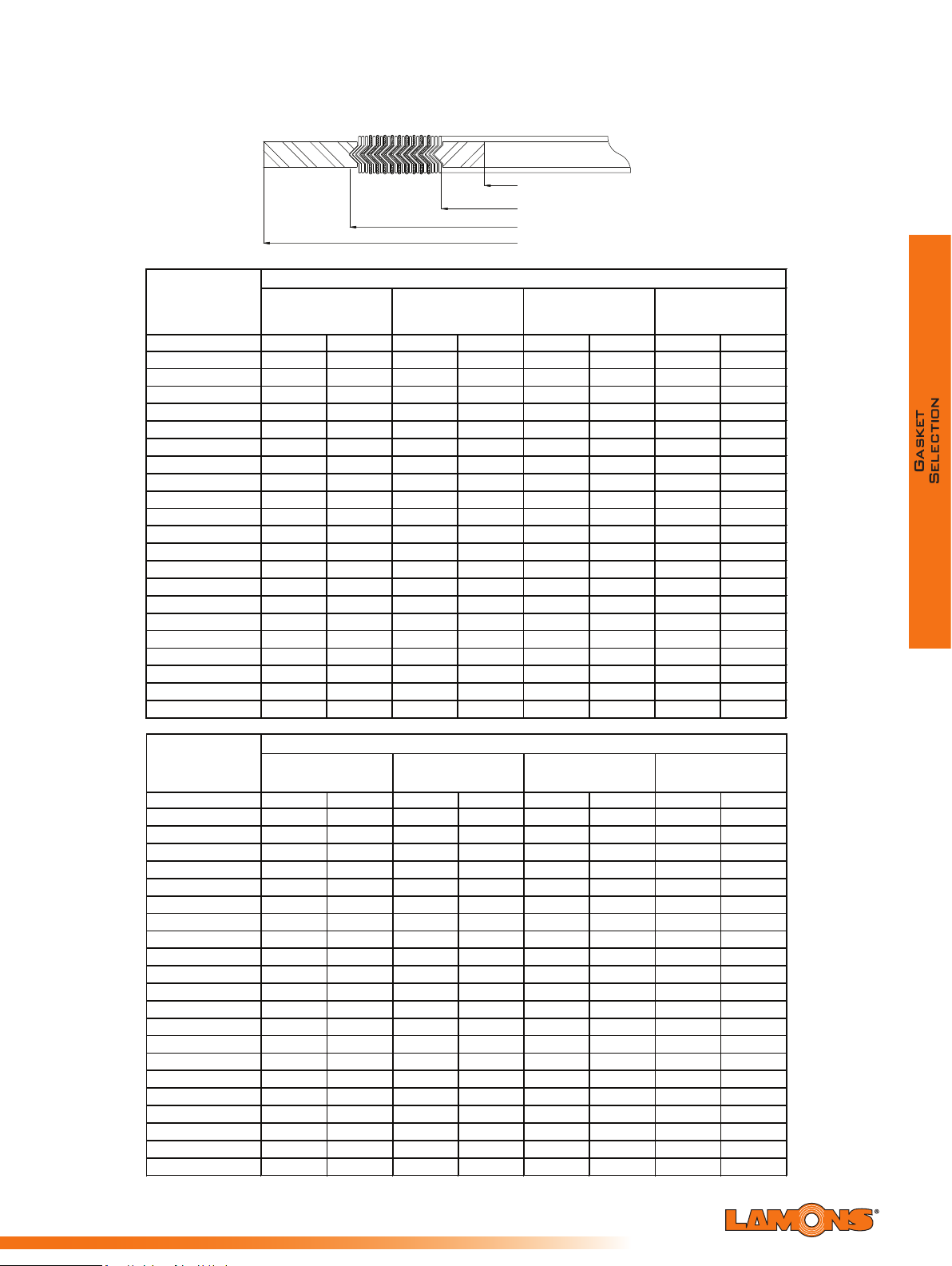
Sealing Global - Servicing Local
Inches mm Inches mm Inches mm Inches mm
1/4* - - 0.50 12.7 0.88 22.2 1.75 44.5
1/2 0.56 14.2 0.75 19.1 1.25 31.8 2.13 54.0
3/4 0.81 20.6 1.00 25.4 1.56 39.7 2.63 66.7
1 1.06 26.9 1.25 31.8 1.88 47.6 2.88 73.0
1 1/4 1.50 38.1 1.88 47.6 2.38 60.3 3
1 1/2 1.75 44.5 2.13 54.0 2.75 69.9 3.75 95.3
2 2.19 55.6 2.75 69.9 3.38 85.7 4.38 111.1
2 1/2 2.62 66.5 3.25 82.6 3.88 98.4 5.13 130.2
3 3.19 81.0 4.00 101.6 4.75 120.7 5.88 149.2
3 1/2 4.13 104.8 5.25 133.4 6.38 161.9
4 4.04 102.6 4.75 120.7 5.88 149.2 7.63 193.7
5 5.05 128.3 5.81 147.6 7.00 177.8 9.50 241.3
6 6.10 154.9 6.88 174.6 8.25 209.6 10.50 266.7
8 8.10 205.7 8.88 225.4 10.38 263.5 12.63 320.7
10.05 255.3 10.81 274.6 12.50 317.5 15.75 400.1
12
10
12.10 307.3 12.88 327.0 14.75 374.7 18.00 457.2
14 13.50 342.9 14.25 362.0 16.00 406.4 19.38 492.1
16 15.35 389.9 16.25 412.8 18.25 463.6 22.25 565.2
18 17.25 438.2 18.50 469.9 20.75 527.1 24.13 612.8
20 19.25 489.0 20.50 520.7 22.75 577.9 26.88 682.6
24 23.25 590.6 24.75 628.7 27.00 685.8 31.13 790.6
Inches mm Inches mm Inches mm Inches mm
1/4* - - - - - - - -
1/2 0.56 14.2 0.75 19.1 1.25 31.8 2.50 63.5
3/4 0.81
20.6 1.00 25.4 1.56 39.7 2.75 69.9
1 1.06 26.9 1.25 31.8 1.88 47.6 3.13 79.4
1 1/4 1.31 33.3 1.56 39.7 2.38 60.3 3.50 88.9
1 1/2 1.63 41.4 1.88 47.6 2.75 69.9 3.88 98.4
2 2.06 52.3 2.31 58.7 3.38 85.7 5.63 142.9
2 1/2 2.50 63.5 2.75 69.9 3.88 98.4 6.5
3 3.10 78.7 3.75 95.3 4.75 120.7 6.63 168.3
3 1/2* 4.13 104.8 5.25 133.4 7.50 190.5
4 4.04 102.6 4.75 120.7 5.88 149.2 8.13 206.4
5 5.05 128.3 5.81 147.6
6 6.10 154.9 6.88 174.6 8.25 209.6 11.38 288.9
8 7.75 196.9 8.75 222.3 10.13 257.2
10 9.69 246.1 10.88 276.2 12.25 311.2 17.13 435.0
12 11.50 292.1 12.75 323.9 14.50 368.3 19.63 498.5
14 12.63 320.8 14.00 355.6 15.75 400.1 20.50 520.7
16 14.75 374.7 16.25 412.8 18.00 457.2 22.63 574.7
18 16.75 425.5 18.25 463.6 20.50 520.7 25.13 638.2
20 19.00 482.6 20.50 520.7 22.50 571.5 27.50 698.5
24 23.25** 590.6 24.75 628.7 26.75 679.5 33.00 83
*Not Listed in ASME B16.20 ** Inner rings are required
Class 600
Nominal Pipe
Size (NPS)
Class 400
Inner Ring Inside
Diameter (ID)
Class 1500
Diameter (OD)
Class 900
Inner Ring Inside
Diameter (ID)
Nominal Pipe
Size (NPS)
Diameter (OD)
Class 300
Class 2500
3.50 88.9
3.50 88.9
Dimensions for Style WRI per ASME B16.20
to Suit ASME B16.5 Flanges
INNER RING INSIDE DIAMETER (ID)
WINDING INSIDE DIAMETER (ID)
WINDING OUTSIDE DIAMETER (OD)
GUIDE RING OUTSIDE DIAMETER (OD)
Nominal Pipe
Size (NPS)
1/4* - - 0.50 12.7 0.88 22.2 1.75 44.5
1/2 0.56 14.2 0.75 19.1 1.25 31.8 2.13 54.0
3/4 0.81 20.6 1.00 25.4 1.56 39.7 2.63 66.7
1 1.06 26.9 1.25 31.8 1.88 47.6 2.88 73.0
1 1/4 1.50 38.1 1.88 47.6 2.38 60.3 3.25 82.6
1 1/2 1.75 44.5 2.13 54.0 2.75 69.9 3.75 95.3
2 2.19 55.6 2.75 69.9 3.38 85.7 4.38 111.1
2 1/2 2.62 66.5 3.25 82.6 3.88 98.4 5.13 130.2
3 3.19 81.0 4.00 101.6 4.75 120.7 5.88 149.2
3 1/2* 4.50 114.3 5.25 133.4 6.50 165.1
4 4.19 106.4 5.00 127.0 5.88 149.2 7.13 181.0
5 5.19 131.8 6.13 155.6 7.00 177.8 8.50 215.9
6 6.19 157.2 7.19 182.6 8.25 209.6 9.88 250.8
8 8.50 215.9 9.19 233.4 10.38 263.5 12.13 308.0
10 10.56 268.2 11.31 287.3 12.50 317.5 14.25 362.0
12 12.50 317.5 13.38 339.7 14.75 374.7 16.63 422.3
14 13.75 349.3 14.63 371.5 16.00 406.4 19.13 485.8
16 15.75 400.1 16.63 422.3 18.25 463.6 21.25 539.8
18 17.69 449.3 18.69 474.7 20.75 527.1 23.50 596.9
20 19.69 500.1 20.69 525.5 22.75 577.9 25.75 654.1
24 23.75 603.3 24.75 628.7 2
Inner Ring Inside
Diameter (ID)
Inches mm Inches mm Inches mm Inches mm
3.50 88.9
Winding Inside
Diameter (ID)
Winding Outside
Diameter (OD)
7.00 685.8 30.50 774.7
Guide Ring Outside
Diameter (OD)
Nominal Pipe
Size (NPS)
1/4* - - 0.50 12.7 0.88 22.2 1.75 44.5
1/2 0.56 14.2 0.75 19.1 1.25 31.8 2.13 54.0
3/4 0.81 20.6 1.00 25.4 1.56 39.7 2.63 66.7
1 1.06 26.9 1.25 31.8 1.88 47.6 2.88 73.0
1 1/4 1.50 38.1 1.88 47.6 2.38 60.3 3.25 82.6
1 1/2 1.75 44.5 2.13 54.0 2.75 69.9 3.75 95.3
2 2.19 55.6 2.75 69.9 3.38 85.7 4.38 111.1
2 1/2 2.62 66.5 3.25 82.6 3.88 98.4 5.13
3 3.19 81.0 4.00 101.6 4.75 120.7 5.88 149.2
3 1/2* 4.13 104.8 5.25 133.4 6.38 161.9
4 4.04 102.6 4.75 120.7 5.88 149.2 7.00 177.8
5 5.05 128.3 5.81 147.6 7.00 177.8 8.38 212.7
6 6.10 154.9 6.88 174.6 8.25 209.6 9.75 247.7
8 8.10 205.7 8.88 225.4 10.38 263.5 12.00 304.8
10 10.05 255.3 10.81 274.6 12.50 317.5 14.13 358.8
12 12.10 307.3 12.88 327.0 14.75 374.7 16.50 419.1
14 13.50 342.9 14.25 362.0 16.00 406.4 19.00 482.6
16 15.35 389.9 16.25 412.8 18.25 463.6 21.13 536.6
18 17.25 438.2 18.50 469.9 20.75 527.1 23.38 593.7
20 19.25 489.0 20.50 520.7 22.75 577.9 25.50 647.7
24 23.25 590.6 24.75 628.7 27.00 685.8 30.25 768.4
*Not Listed in ASME B16.20
Inner Ring Inside
Diameter (ID)
Inches mm Inches mm Inches mm Inches mm
3.50 88.9
Winding Inside
Diameter (ID)
Winding Outside
Diameter (OD)
Guide Ring Outside
Diameter (OD)
130.2
73

Dimensions for Style WRI per ASME B16.20
Inches mm Inches mm Inches mm Inches mm
Inches mm Inches mm Inches mm Inches mm
1/4* - - - - - - - -
1/4* - - - - - - - -
1/2 0.56 14.2 0.75 19.1 1.25 31.8 2.50 63.5
1/2 0.56 14.2 0.75 19.1 1.25 31.8 2.75 69.9
3/4 0.81 20.6 1.00 25.4 1.56 39.7 2.75 69.9
3/4 0.81 20.6 1.00 25.4 1.56 39.7 3.00 76.2
1 1.06 26.9 1.25 31.8 1.88 47.6 3.13 79.4
1 1.06 26.9 1.25 31.8 1.88 47.6 3.38 85.7
1 1/4 1.31 33.3 1.56 39.7 2.38 60.3 3.50 88.9
1 1/4 1.31 33.3 1.56 39.7 2.38 60.3 4.13 104.8
1 1/2 1.63 41.4 1.88 47.6 2.75 69.9 3.88 98.4
1 1/2 1.63 41.4 1.88
2 2.06 52.3 2.31 58.7 3.38 85.7 5.63 142.9
2 2.06 52.3 2.31 58.7 3.38 85.7 5.75 146.1
2 1/2 2.50 63.5 2.75 69.9 3.88 98.4 6.50 165.1
2 1/2 2.50 63.5 2.75 69.9 3.88 98.4 6.63 168.3
3 3.10 78.7 3.63 92.1 4.75 120.7 6.88 174.6
3 3.10 78.7 3.63 92.1 4.75 120.7 7.75 196.9
3 1/2* 4.13 104.8 5.25 133.
3 1/2* - - - - - -
4 3.85 97.8 4.63 117.5 5.88 149.2 8.25 209.6
4 3.85** 97.8** 4.63 117.5 5.88 149.2 9.25 235.0
5 4.90 124.5 5.63 142.9 7.00 177.8 10.00 254.0
5 4.90** 124.5** 5.63 142.9 7.00 177.8 11.00 279.4
6 5.80 147.3 6.75 171.5 8.25 209.6 11.13 282.6
6 5.80** 147.3** 6.75 171.5 8.25 209.6 12.50 317.5
8 7.75 196.9 8.50 215.9 10.13 257.2 13.88 352.4
8 7.75** 196.9** 8.50 215.9 10.13 257.2 15.25 387.4
10 9.69 246.1 10.50 266.7 12.25 311.2 17.13 435.0
10 9.69** 246.1** 10.63 269.9 12.25 311.2 18.75 476.3
12 11.50** 292.1** 12.75 323.9 14.50 368.3 20.50 520.7
12 11.50** 292.1** 12.50 317.5 14.50 368.3 21.63 549.3
14 12.
63** 320.8** 14.25 362.0 15.75 400.1 22.75 577.9
*Not Listed in ASME B16.20
16 14.50** 368.3** 16.00 406.4 18.00 457.2 25.25 641.4
** Inner rings are required
18 16.75** 425.5** 18.25 463.6 20.50 520.7 27.75 704.9
20 18.75** 476.3** 20.25 514.4 22.50 571.5 29.75 755.7
24 22.75** 577.9** 24.25 616.0 26.75 679.5 35.50 901.7
Class 600
Class 1500
Diameter (OD)
Class 900
Nominal Pipe
Size (NPS)
Inner Ring Inside
Diameter (ID)
Diameter (ID)
Diameter (OD)
Inner Ring Inside
Diameter (ID)
Nominal Pipe
Size (NPS)
Class 2500
3.50 88.9
3.50 88.9
to Suit ASME B16.5 Flanges
INNER RING INSIDE DIAMETER (ID)
WINDING INSIDE DIAMETER (ID)
WINDING OUTSIDE DIAMETER (OD)
GUIDE RING OUTSIDE DIAMETER (OD)
Nominal Pipe
Size (NPS)
1/4* - - 0.50 12.7 0.88 22.2 1.75 44.5
1/2 0.56 14.2 0.75 19.1 1.25 31.8 2.13 54.0
3/4 0.81 20.6 1.00 25.4 1.56 39.7 2.63 66.7
1 1.06 26.9 1.25 31.8 1.88 47.6 2.88 73.0
1 1/4 1.50 38.1 1.88 47.6 2.38 60.3 3
1 1/2 1.75 44.5 2.13 54.0 2.75 69.9 3.75 95.3
2 2.19 55.6 2.75 69.9 3.38 85.7 4.38 111.1
2 1/2 2.62 66.5 3.25 82.6 3.88 98.4 5.13 130.2
3 3.19 81.0 4.00 101.6 4.75 120.7 5.88 149.2
3 1/2 4.13 104.8 5.25 133.4 6.38 161.9
4 4.04 102.6 4.75 120.7 5.88 149.2 7.63 193.7
5 5.05 128.3 5.81 147.6 7.00 177.8 9.50 241.3
6 6.10 154.9 6.88 174.6 8.25 209.6 10.50 266.7
8 8.10 205.7 8.88 225.4 10.38 263.5 12.63 320.7
10
10.05 255.3 10.81 274.6 12.50 317.5 15.75 400.1
12
14 13.50 342.9 14.25 362.0 16.00 406.4 19.38 492.1
16 15.35 389.9 16.25 412.8 18.25 463.6 22.25 565.2
18 17.25 438.2 18.50 469.9 20.75 527.1 24.13 612.8
20 19.25 489.0 20.50 520.7 22.75 577.9 26.88 682.6
24 23.25 590.6 24.75 628.7 27.00 685.8 31.13 790.6
Nominal Pipe
Size (NPS)
1/4* - - - - - - - 1/2 0.56 14.2 0.75 19.1 1.25 31.8 2.50 63.5
3/4 0.81
1 1.06 26.9 1.25 31.8 1.88 47.6 3.13 79.4
1 1/4 1.31 33.3 1.56 39.7 2.38 60.3 3.50 88.9
1 1/2 1.63 41.4 1.88 47.6 2.75 69.9 3.88 98.4
2 2.06 52.3 2.31 58.7 3.38 85.7 5.63 142.9
2 1/2 2.50 63.5 2.75 69.9 3.88 98.4 6.50 165.1
3 3.10 78.7 3.75 95.3 4.75 120.7 6.63 168.3
3 1/2* 4.13 104.8 5.25 133.4 7.50 190.5
4 4.04 102.6 4.75 120.7 5.88 149.2 8.13 206.4
5 5.05 128.3 5.81 147.6 7.00 177.8 9.75 247.7
6 6.10 154.9 6.88 174.6 8.25 209.6 11.38 288.9
8 7.75 196.9 8.75 222.3 10.13 257.2
10 9.69 246.1 10.88 276.2 12.25 311.2 17.13 435.0
12 11.50 292.1 12.75 323.9 14.50 368.3 19.63 498.5
14 12.63 320.8 14.00 355.6 15.75 400.1 20.50 520.7
16 14.75 374.7 16.25 412.8 18.00 457.2 22.63 574.7
18 16.75 425.5 18.25 463.6 20.50 520.7 25.13 638.2
20 19.00 482.6 20.50 520.7 22.50 571.5 27.50 698.5
24 23.25** 590.6 24.75 628.7 26.75 679.5 33.00 83
*Not Listed in ASME B16.20 ** Inner rings are required
Inner Ring Inside
Diameter (ID)
Inches mm Inches mm Inches mm Inches mm
3.50 88.9
12.10 307.3 12.88 327.0 14.75 374.7 18.00 457.2
Inner Ring Inside
Inches mm Inches mm Inches mm Inches mm
20.6 1.00 25.4 1.56 39.7 2.75 69.9
3.50 88.9
Winding Inside
Diameter (ID)
Winding Inside
Diameter (ID)
Winding Outside
Diameter (OD)
Winding Outside
Guide Ring Outside
Diameter (OD)
.25 82.6
Guide Ring Outside
14.13 358.8
8.2
Sealing Global - Servicing Local

Sealing Global - Servicing Local
Class 1500
Class 2500
Dimensions for Style WRI per ASME B16.20
to Suit ASME B16.5 Flanges
INNER RING INSIDE DIAMETER (ID)
WINDING INSIDE DIAMETER (ID)
WINDING OUTSIDE DIAMETER (OD)
GUIDE RING OUTSIDE DIAMETER (OD)
Nominal Pipe
Size (NPS)
1/4* - - - - - - - 1/2 0.56 14.2 0.75 19.1 1.25 31.8 2.50 63.5
3/4 0.81 20.6 1.00 25.4 1.56 39.7 2.75 69.9
1 1.06 26.9 1.25 31.8 1.88 47.6 3.13 79.4
1 1/4 1.31 33.3 1.56 39.7 2.38 60.3 3.50 88.9
1 1/2 1.63 41.4 1.88 47.6 2.75 69.9 3.88 98.4
2 2.06 52.3 2.31 58.7 3.38 85.7 5.63 142.9
2 1/2 2.50 63.5 2.75 69.9 3.88 98.4 6.50 165.1
3 3.10 78.7 3.63 92.1 4.75 120.7 6.88 174.6
3 1/2* 4.13 104.8 5.25 133.
4 3.85 97.8 4.63 117.5 5.88 149.2 8.25 209.6
5 4.90 124.5 5.63 142.9 7.00 177.8 10.00 254.0
6 5.80 147.3 6.75 171.5 8.25 209.6 11.13 282.6
8 7.75 196.9 8.50 215.9 10.13 257.2 13.88 352.4
10 9.69 246.1 10.50 266.7 12.25 311.2 17.13 435.0
12 11.50** 292.1** 12.75 323.9 14.50 368.3 20.50 520.7
14 12.
16 14.50** 368.3** 16.00 406.4 18.00 457.2 25.25 641.4
18 16.75** 425.5** 18.25 463.6 20.50 520.7 27.75 704.9
20 18.75** 476.3** 20.25 514.4 22.50 571.5 29.75 755.7
24 22.75** 577.9** 24.25 616.0 26.75 679.5 35.50 901.7
Inner Ring Inside
Diameter (ID)
Inches mm Inches mm Inches mm Inches mm
3.50 88.9
63** 320.8** 14.25 362.0 15.75 400.1 22.75 577.9
Winding Inside
Diameter (ID)
Winding Outside
Diameter (OD)
Guide Ring Outside
Diameter (OD)
4 7.38 187.3
Nominal Pipe
Size (NPS)
1/4* - - - - - - - 1/2 0.56 14.2 0.75 19.1 1.25 31.8 2.75 69.9
3/4 0.81 20.6 1.00 25.4 1.56 39.7 3.00 76.2
1 1.06 26.9 1.25 31.8 1.88 47.6 3.38 85.7
1 1/4 1.31 33.3 1.56 39.7 2.38 60.3 4.13 104.8
1 1/2 1.63 41.4 1.88
2 2.06 52.3 2.31 58.7 3.38 85.7 5.75 146.1
2 1/2 2.50 63.5 2.75 69.9 3.88 98.4 6.63 168.3
3 3.10 78.7 3.63 92.1 4.75 120.7 7.75 196.9
3 1/2* - - - - - 4 3.85** 97.8** 4.63 117.5 5.88 149.2 9.25 235.0
5 4.90** 124.5** 5.63 142.9 7.00 177.8 11.00 279.4
6 5.80** 147.3** 6.75 171.5 8.25 209.6 12.50 317.5
8 7.75** 196.9** 8.50 215.9 10.13 257.2 15.25 387.4
10 9.69** 246.1** 10.63 269.9 12.25 311.2 18.75 476.3
12 11.50** 292.1** 12.50 317.5 14.50 368.3 21.63 549.3
*Not Listed in ASME B16.20
Inner Ring Inside
Diameter (ID)
Inches mm Inches mm Inches mm Inches mm
3.50 88.9
** Inner rings are required
Winding Inside
Diameter (ID)
47.6 2.75 69.9 4.63 117.5
Winding Outside
Diameter (OD)
Guide Ring Outside
Diameter (OD)
75

Spiral-Wound WR/WRI Tolerances
per ASME B16.20 Specifications
• The winding thickness: ±0.005” (0.13 mm) measured across the metallic por on
of the winding not including the ller.
• The winding outside diameter
o NPS ½ through NPS 8 is ±1/32” (±0.8 mm)
o NPS 10 through NPS 24 is +1/16”, - 1/32” (+1.5 mm, -0.8 mm)
• The winding inside diameter
o NPS ½ through NPS 8 is ±1/64” (±0.4 mm )
o NPS 10 through NPS 24 is ±1/32” (±0.8 mm)
• The guide ring outside diameter: ±1/32” (±0.8 mm)
• The guide ring and inner thickness shall be from 0.117”
(2.97 mm) to 0.131” (3.33 mm)
• The inner ring inside diameter:
o NPS ½ through 3 is ±1/32” (±0.8 mm)
o NPS 4 through 24 is ±1/16” (±1.5 mm)
Table for Minimum Pipe Wall Thickness that is Suitable
for use with Standard Inner Rings per the ASME B16.20
Nominal
Pipe Size
(NPS)
1/2
3/4 Sched ul e 80
1
1 1/4
1 1/2
2
2 1/2
3 Sche dul e 40
3 1/2*
4
5
6
8
10
12
14
16
18
20
24
150 300 400 600 900 1500 2500
Sched ul e 10S Sched ul e 30
Pressure Class
Sched ul e 80
Sched ul e 80
General Notes per ASME B16.20:
• The pipe wall schedules iden ed represent the minimum pipe wall thickness suitable for use with inner rings
for ASME B16.5 anges (reference ASME B 36.10M and B36.19M).
• Gasket with inner rings should be used only with socket welding, lapped, welding neck, and integral anges.
* Not Listed in ASME B16.20
Sealing Global - Servicing Local

Sealing Global - Servicing Local
Table for Limitations on the Maximum ASME B16.5 Flange Bore
150 300 400 600 900 (1) 1500 (1) 2500 (1)
1/2
3/4
WN Flange onl y
1 No Fla nges
1 1/4 Use 600
SO Fl ange (3)
1 1/2
WN Flange (2)
2
2 1/2
3
4
5
6
8
10
12
14
16
18 No Fla nges
20
24
SO Fl ange (3)
Nominal
Pipe Size
(NPS)
Pressure Class
WN Flange onl y (2)
SO Fl ange (3)
WN Flange with Schedule 10S
bore descri bed in ASME
B36.19M (Excl udes nozzle (4)
and SO Flanges) (5)
WN Flange, any bore
SO and WN
Flange
any bore
WN flange with SW bore
(include nozzle (4)
but excl udes SO flange)
WN flange only (2)
WN Flange (2)
SO and WN Flange any bore
WN Flange with Schedule
0S bore described i n
ASME B36.19M
(Includes nozzl e (4)
but excludes SO Flanges)
WN flange with schedule
80 bore (excludes nozzle
(4) and SO fla nge) (5)
No Fla nges
Use 1500
for use with Standard ASME B16.20 Spiral Wound Gaskets
Abbreviaons:
SO = slip on and threaded
WN = welding neck
SW = standard wall
Notes per the ASME B16.20 specicaon:
1. Inner rings are required for class 900 NPS 24, class 1500 NPS 12 through 24, and class 2500 NPS 4 through NPS 12 per the ASME B16.20. These
inner rings may extend into the pipe bore a maximum of 1/16” (1.5 mm) under the worst combinaon of maximum bore, eccentric installaon,
and addive tolerances.
2. In these sizes, the gasket is suitable for a welding neck ange with a standard wall bore, if the gasket and the anges are assembled concentrically.
This also applies to a nozzle. It is the user’s responsibility to determine if the gasket is sasfactory for a ange or any larger bore.
3. Gaskets in theses sizes are suitable for slip on anges only if the gaskets and anges are assembled concentrically
4. A nozzle is a long welding neck; the bore equals the ange NPS
5. A NPS 24 gasket is suitable for nozzles.
77

Dimensions for Style WR/WRI to Suit AWWA C207
Class E Slip-On and Welding Neck Flanges
INNER RING INSIDE DIAMETER (ID)
WINDING INSIDE DIAMETER (ID)
WINDING OUTSIDE DIAMETER (OD)
GUIDE RING OUTSIDE DIAMETER (OD)
Nominal Pipe
Size (NPS)
Inner
Ring Inside
Diameter (ID)
Inches mm Inches mm Inches mm Inches mm
Winding Inside
Diameter (ID)
Class 125
Winding Outside
Diameter (OD)
Guide Ring Outside
Diameter (OD)
22 22.00 558.8 22.75 577.9 24.00 609.6 26.00 660.4
26 26.00 660.4 26.50 673.1 27.75 704.9 30.50 774.7
28 28.00 711.2 28.50 723.9 27.75 704.9 32.75 831.9
30 30.00 762.0 30.50 774.7 31.75 806.5 34.75 882.7
32 32.00 812.8 32.50 825.5 33.88 860.4 37.00 939.8
34 34.00 863.6 34.50 876.3 35.88 911.2 39.00 990.6
36 36.00 914.4 36.50 927.1 38.13 968.4 41.25 1047.8
38 38.00 965.2 38.50 977.9 40.13 1019.2 43.75 1111.3
40 40.00 1016.0 40.50 1028.7 42.13
1070.0 45.75 1162.1
42 42.00 1066.8 42.50 1079.5 44.25 1124.0 48.00 1219.2
44 44.00 1117.6 44.50 1130.3 46.38 1177.9 50.25 1276.4
46 46.00 1168.4 46.50 1181.1 48.38 1228.7 52.25 1327.2
48 48.00 1219.2 48.50 1231.9 50.38 1279.5 54.50 1384.3
50 50.00 1270.0 50.50 1282.7 52.50 1333.5 56.50 1435.1
52 52.00 1320.8 52.50 1333.5 54.50 1384.3 58.75 1492.3
54 54.00 1371.6 54.50 1384.3 56.50 1435.1 61.00 1549.4
60 60.00 1524.0 60.50 1536.7 62.50 1587.5 67.50 1714.5
Nominal Pipe
Size (NPS)
Inner Ring Inside
Diameter (ID)
Inches mm Inches mm Inches mm Inches mm
Winding Inside
ameter (ID)
Di
Class 175
Winding Outside
Diameter (OD)
Guide Ring Outside
Diameter (OD)
26 26.00 660.4 26.50 673.1 27.75 704.9 29.13 739.8
28 28.00 711.2 28.50 723.9 29.75 755.7 31.13 790.6
30 30.00 762.0 30.50 774.7 31.75 806.5 33.38 847.7
32 32.00 812.8 32.50 825.5 33.75 857.3 35.38 898.5
34 34.00 863.6 34.50 876.3 35.88 911.2 37.50 952.5
36 36.00 914.4 36.50 927.1 37.88 962.0 39.50 1003.3
38 38.00 965.2 38.50 977.9 39.88 1012.8 41.50 1054.1
40 40.00 1016.0 40.50 1028.7 42.00 1066.8 43.50 1104.9
42 42.00 1066.8 42.50 1079.5 4
4.00 1117.6 45.88 1165.2
44 44.00 1117.6 44.50 1130.3 46.00 1168.4 47.88 1216.0
46 46.00 1168.4 46.50 1181.1 48.00 1219.2 49.88 1266.8
48 48.00 1219.2 48.50 1231.9 50.13 1273.2 51.88 1317.6
50 50.00 1270.0 50.50 1282.7 52.25 1327.2 53.88 1368.4
52 52.00 1320.8 52.50 1333.5 54.38 1381.1 56.13 1425.6
54 54.00 1371.6 54.50 1384.3 56.38 1431.9 58.13 1476.4
60 60.00 1524.0 60.50 1536.7 62.50 1587.5 61.13 1552.6
Sealing Global - Servicing Local

Sealing Global - Servicing Local
Dimensions for Style WR/WRI to Suit AWWA C207
Inches mm Inches mm Inches mm Inches mm
Class E Slip-On and Welding Neck Flanges
INNER RING INSIDE DIAMETER (ID)
WINDING INSIDE DIAMETER (ID)
WINDING OUTSIDE DIAMETER (OD)
GUIDE RING OUTSIDE DIAMETER (OD)
Nominal Pipe
Size (NPS)
Inner Ring Inside
Diameter (ID)
Winding Inside
Diameter (ID)
Class 250
Winding Outside
Diameter (OD)
Guide Ring Outside
Diameter (OD)
26 26.00 660.4 26.50 673.1 27.75 704.9 32.75 831.9
28 28.00 711.2 28.50 723.9 29.75 755.7 35.25 895.4
30 30.00 762.0 30.50 774.7 31.75 806.5 37.50 952.5
32 32.00 812.8 32.50 825.5 33.88 860.4 39.75 1009.7
34 34.00 863.6 34.50 876.3 35.88 911.2 41.75 1060.5
36 36.00 914.4 36.50 927.1 38.13 968.4 44.00 1117.6
38 38.00 965.2 38.50 977.9 40.13 1019.2 46.00 1168.4
40 40.00 1016.0 40.50 1028.7 42.13 1070.0 48.25 1225.6
42 42.00 1066.8 42.50 1079.5 44.25 1124.0 50.75 1289.1
44 44.00 11
17.6 44.50 1130.3 46.38 1177.9 53.00 1346.2
46 46.00 1168.4 46.50 1181.1 48.38 1228.7 55.25 1403.4
48 48.00 1219.2 48.50 1231.9 50.38 1279.5 58.75 1492.3
Nominal Pipe
Size (NPS)
Inner Ring Inside
Diamete
r (ID)
Inches mm Inches mm Inches mm Inches mm
Winding Inside
Diameter (ID)
Class 350
Winding Outside
Diameter (OD)
Guide Ring Outside
Diameter (OD)
26 26.00 660.4 26.50 673.1 27.75 704.9 29.63 752.5
28 28.00 711.2 28.50 723.9 29.75 755.7 31.63 803.3
30 30.00 762.0 30.50 774.7 31.75 806.5 33.88 860.4
32 32.00 812.8 32.50 825.5 33.88 860.4 35.88 911.2
34 34.00 863.6 34.50 876.3 35.88 911.2 37.88 962.0
36 36.00 914.4 36.50 927.1 38.13 968.4 40.38 1025.5
38 38.00 965.2 38.50 977.9 40.13 1019.2 42.38 1076.3
40 40.00 1016.0 40.50 1028.7 42.13 1070.0 44.38 1127.1
42 42.00 1066.8 42.50 1079.5 4
4.25 1124.0 46.63 1184.3
44 44.00 1117.6 44.50 1130.3 46.38 1177.9 49.00 1244.6
46 46.00 1168.4 46.50 1181.1 48.38 1228.7 51.00 1295.4
48 48.00 1219.2 48.50 1231.9 50.38 1279.5 53.00 1346.2
52 52.00 1320.8 52.50 1333.5 54.25 1378.0 57.38 1457.3
54 54.00 1371.6 54.50 1384.3 56.50 1435.1 59.38 1508.1
60 60.00 1524.0 60.50 1536.7 62.50 1587.5 65.38 1660.5
66 66.00 1676.4 66.50 1689.1 68.50 1739.9 72.50 1841.5
79

Dimensions for Style WR/WRI per ASME B16.20 to Suit
Inches mm Inches mm Inches mm Inches mm
Inches mm Inches mm Inches mm Inches mm
ASME B16.47 Series A or MSS-SP- 44 Flanges
INNER RING INSIDE DIAMETER (ID)
WINDING INSIDE DIAMETER (ID)
WINDING OUTSIDE DIAMETER (OD)
GUIDE RING OUTSIDE DIAMETER (OD)
Nominal Pipe
Size (NPS)
Inner Ring Inside
Diameter (ID)
Winding Inside
Diameter (ID)
Class 150
Winding Outside
Diameter (OD)
Guide Ring Outside
Diameter (OD)
22* - - 22.75 577.9 24.00 609.6 26.00 660.4
26 25.75 654.1 26.50 673.1 27.75 704.9 30.50 774.7
28 27.75 704.9 28.50 723.9 29.75 755.7 32.75 831.9
30 29.75 755.7 30.50 774.7 31.75 806.5 34.75 882.7
32 31.75 806.5 32.50 825.5 33.88 860.4 37.00 939.8
34 33.75 857.3 34.50 876.3 35.88 911.2 39.00 990.6
36 35.75 908.1 36.50 927.1 38.13 968.4 41.25 1047.8
38 37.75 958.9 38.50 977.9 40.13 1019.2 43.75 1111.3
40 39.75 1009.7 40.50 1028.7 42.13 1070.0 45.75 1162.1
42 41.75 1060.5 42.50 1079
.5 44.25 1124.0 48.00 1219.2
44 43.75 1111.3 44.50 1130.3 46.38 1177.9 50.25 1276.4
46 45.75 1162.1 46.50 1181.1 48.38 1228.7 52.25 1327.2
48 47.75 1212.9 48.50 1231.9 50.38 1279.5 54.50 1384.3
50 49.75 1263.7 50.50 1282.7 52.50 1333.5 56.50 1435.1
52 51.75 1314.5 52.50 1333.5 54.50 1384.3 58.75 1492.3
54 53.50 1358.9 54.50 1384.3 56.50 1435.1 61.00 1549.4
56 55.50 1409.7 56.50 1435.1 58.50 1485.9 63.25 1606.6
58 57.50 1460.5 58.50 1485.9 60.50 1536.7 65.50 1663.7
60 59.50 1
Nominal Pipe
Size (NPS)
Inner Ring Inside
Diameter (ID)
511.3 60.50 1536.7 62.50 1587.5 67.50 1714.5
Class 300
Winding Inside
Diameter (ID)
Winding Outside
Diameter (OD)
Guide Ring Outside
Diameter (OD)
22* - - 22.75 577.9 24.75 628.7 27.75 704.9
26 25.75 654.1 27.00 685.8 29.00 736.6 32.88 835.0
28 27.75 704.9 29.00 736.6 31.00 787.4 35.38 898.5
30 29.75 755.7 31.25 793.8 33.25 844.6 37.50 952.5
32 31.75 806.5 33.50 850.9 35.50 901.7 39.63 1006.5
34 33.75 857.3 35.50 901.7 37.50 952.5 41.63 1057.3
36 35.75 908.1 37.63 955.7 39.63 1006.5 44.00 1117.6
38 37.50 952.5 38.50 977.9 40.00 1016.0 41.50 1054.1
40 39.50 1003.3 40.25 1022.4 42.13 1070.0 43.88 1114.4
42 41.50 1054.1 42.25 1
44 43.50 1104.9 44.50 1130.3 46.50 1181.1 48.00 1219.2
46 45.38 1152.7 46.38 1177.9 48.38 1228.7 50.13 1273.2
48 47.63 1209.8 48.63 1235.1 50.63 1285.9 52.13 1324.0
50 49.00 1244.6 51.00 1295.4 53.00 1346.2 54.25 1378.0
52 52.00 1320.8 53.00 1346.2 55.00 1397.0 56.25 1428.8
54 53.25 1352.6 55.25 1403.4 57.25 1454.2 58.75 1492.3
56 55.25 1403.4 57.25 1454.2 59.25 1505.0 60.75 1543.1
58 57.00 1447.8 59.50 1511.3 61.50 1562.1 62.75 1593.9
60 60.
*Not li ste d in ASME B16.20
Sealing Global - Servicing Local
00 1524.0 61.50 1562.1 63.50 1612.9 64.75 1644.7
073.2 44.13 1120.8 45.88 1165.2

Sealing Global - Servicing Local
Dimensions for Style WR/WRI per ASME B16.20 to Suit
Inches Inches mm Inches mm Inches mm Inches mm
ASME B16.47 Series A or MSS-SP- 44 Flanges
INNER RING INSIDE DIAMETER (ID)
WINDING INSIDE DIAMETER (ID)
WINDING OUTSIDE DIAMETER (OD)
GUIDE RING OUTSIDE DIAMETER (OD)
Nominal
Pipe Size
(NPS)
22* - - 22.75 577.9 24.75 628.7 27.63 701.7
26 26.00 660.4 27.00 685.8 29.00 736.6 32.75 831.9
28 28.00 711.2 29.00 736.6 31.00 787.4 35.13 892.2
30 29.75 755.7 31.25 793.8 33.25 844.6 37.25 946.2
32 32.00 812.8 33.50 850.9 35.50 901.7 39.50 1003.3
34 34.00 863.6 35.50 901.7 37.50 952.5 41.50 1054.1
36 36.13 917.7 37.63 955.7 39.63 1006.5 44.00 1117.6
38 37.50 952.5 38.25 971.6 40.25 1022.4 42.25 1073.2
40 39.38 1000.3 40.38 1025.5 42.38 1076.3 44.38 1127.1
42 41.38 1051.1 42.38 1
44 43.50 1104.9 44.50 1130.3 46.50 1181.1 48.50 1231.9
46 46.00 1168.4 47.00 1193.8 49.00 1244.6 50.75 1289.1
48 47.50 1206.5 49.00 1244.6 52.00 1320.8 53.00 1346.2
50 49.50 1257.3 51.00 1295.4 53.00 1346.2 55.25 1403.4
52 51.50 1308.1 53.00 1346.2 55.00 1397.0 57.25 1454.2
54 53.25 1352.6 55.25 1403.4 57.25 1454.2 59.75 1517.7
56 55.25 1403.4 57.25 1454.2 59.25 1505.0 61.75 1568.5
58 57.25 1454.2 59.25 1505.0 61.25 1555.8 63.75 1619.3
60 59.
Nominal
Pipe Size
(NPS)
Inches Inches mm Inches mm Inches mm Inches mm
22* - - 22.75 577.9 24.75 628.7 28.88 733.4
26 25.50 647.7 27.00 685.8 29.00 736.6 34.13 866.8
28 27.50 698.5 29.00 736.6 31.00 787.4 36.00 914.4
30 29.75 755.7 31.25 793.8 33.25 844.6 38.25 971.6
32 32.00 812.8 33.50 850.9 35.50 901.7 40.25 1022.4
34 34.00 863.6 35.50 901.7 37.50 952.5 42.25 1073.2
36 36.13 917.7 37.63 955.7 39.63 1006.5 44.50 1130.3
38 37.50 952.5 39.00 990.6 41.00 1041.4 43.50 1104.9
40 39.75 1009.7 41.25 1047.8 43.
42 42.00 1066.8 43.50 1104.9 45.50 1155.7 48.00 1219.2
44 43.75 1111.3 45.75 1162.1 47.75 1212.9 50.00 1270.0
46 45.75 1162.1 47.75 1212.9 49.75 1263.7 52.25 1327.2
48 48.00 1219.2 50.00 1270.0 52.00 1320.8 54.75 1390.7
50 50.00 1270.0 52.00 1320.8 54.00 1371.6 57.00 1447.8
52 52.00 1320.8 54.00 1371.6 56.00 1422.4 59.00 1498.6
54 54.25 1378.0 56.25 1428.8 58.25 1479.6 61.25 1555.8
56 56.25 1428.8 58.25 1479.6 60.25 1530.4 63.50 1612.9
58 58.00 1473.2
60 60.25 1530.4 62.75 1593.9 64.75 1644.7 68.25 1733.6
*Not li ste d in ASME B16.20
Inner Ring Inside
Diameter (ID)
75 1517.7 61.75 1568.5 63.75 1619.3 66.25 1682.8
Inner Ring Inside
Diameter (ID)
Winding Inside
Diameter (ID)
Winding Inside
Diameter (ID)
60.50 1536.7 62.50 1587.5 65.50 1663.7
Class 400
Winding Outside
Diameter (OD)
076.3 44.38 1127.1 46.38 1177.9
Class 600
Winding Outside
Diameter (OD)
25 1098.6 45.50 1155.7
Guide Ring Outside
Diameter (OD)
Guide Ring Outside
Diameter (OD)
81

Dimensions for Style WR/WRI per ASME B16.20 to Suit
ASME B16.47 Series A or MSS-SP- 44 Flanges
INNER RING INSIDE DIAMETER (ID)
WINDING INSIDE DIAMETER (ID)
WINDING OUTSIDE DIAMETER (OD)
GUIDE RING OUTSIDE DIAMETER (OD)
Cla
Nominal Pipe
Size (NPS)
22* - - 24.25 616.0 27.00 685.8 33.00 838.2
26 26.00 660.4 27.00 685.8 29.00 736.6 34.75 882.7
28 28.00 711.2 29.00 736.6 31.00 787.4 37.25 946.2
30 30.25 768.4 31.25 793.8 33.25 844.6 39.75 1009.7
32 32.00 812.8 33.50 850.9 35.50 901.7 42.25 1073.2
34 34.00 863.6 35.50 901.7 37.50 952.5 44.75 1136.7
36 36.25 920.8 37.75 958.9 39.75 1009.7 47.25 1200.2
38 39.75 1009.7 40.75 1035.1 42.75 1085.9 47.25 1200.2
40 41.75 1060.5 43.25 1098.6 45.25 1
42 43.75 1111.3 45.25 1149.4 47.25 1200.2 51.25 1301.8
44 45.50 1155.7 47.50 1206.5 49.50 1257.3 53.88 1368.4
46 48.00 1219.2 50.00 1270.0 52.00 1320.8 56.50 1435.1
48 50.00 1270.0 52.00 1320.8 54.00 1371.6 58.50 1485.9
*Not listed in ASME B16.20
**In ne r rings a re requi red
Inner Ring Inside
Diameter (ID)**
Inches mm Inches mm Inches mm Inches mm
Winding Inside
Diameter (ID)
ss 900
Winding Outside
Diameter (OD)
Guide Ring Outside
Diameter (OD)
149.4 49.25 1251.0
Large Spiral Wound Gasket Tolerances per ASME B16.20
to be used with ASME B16.47 Series A Flanges
• The winding thickness is ±0.005” (±0.13 mm) measured across the metallic por on
of the gasket not including the ller
• The winding inside diameter
o NPS 26 through NPS 34 is ±1/32” (±0.8 mm)
o NPS 36 through NPS 60 is ± 3/64” (±1.3 mm)
• The winding outside diameter
o NPS 26 through 60 is ± 1/16” (1.5 mm)
• The guide ring outside diameter tolerance is ±1/32” (±0.8 mm)
• The guide ring and inner thickness shall be from 0.117”
(2.97 mm) to 0.131” (3.33 mm)
• The inner ring inside diameter is: ±1/8” (±3.0 mm)
• These inner rings are suitable for use with pipe walls 0.38” (9.53 mm) or thicker
Sealing Global - Servicing Local

Sealing Global - Servicing Local
Dimensions for Style WR/WRI per ASME B16.20 to Suit
Inches mm Inches mm Inches mm Inches mm
ASME B16.47 Series B or API-605 Flanges
INNER RING INSIDE DIAMETER (ID)
WINDING INSIDE DIAMETER (ID)
WINDING OUTSIDE DIAMETER (OD)
GUIDE RING OUTSIDE DIAMETER (OD)
Nominal Pipe
Size (NPS)
26 25.75 654.05 26.50 673.1 27.50 698.5 28.56 725.5
28 27.75 704.9 28.50 723.9 29.50 749.3 30.56 776.3
30 29.75 755.7 30.50 774.7 31.50 800.1 32.56 827.1
32 31.75 806.5 32.50 825.5 33.50 850.9 34.69 881.1
34 33.75 857.3 34.50 876.3 35.75 908.1 36.81 935.0
36 35.75 908.1 36.50 927.1 37.75 958.9 38.88 987.4
38 37.75 958.9 38.38 974.7 39.75 1009.7 41.13 1044.6
40 39.75 1009.7 40.25 1022.4 41.88 1063.6 43.13 1095.4
42 41.75 1060.5 42.50 1079.5 43.88 1114.4 45.13 1146.2
44 43.75 1111
46 45.75 1162.1 46.50 1181.1 48.19 1224.0 49.44 1255.7
48 47.75 1212.9 48.50 1231.9 50.00 1270.0 51.44 1306.5
50 49.75 1263.7 50.50 1282.7 52.19 1325.6 53.44 1357.3
52 51.75 1314.5 52.50 1333.5 54.19 1376.4 55.44 1408.1
54 53.75 1365.3 54.50 1384.3 56.00 1422.4 57.63 1463.7
56 56.00 1422.4 56.88 1444.6 58.19 1478.0 59.63 1514.5
58 58.19 1478.0 59.08 1500.6 60.19 1528.8 62.19 1579.6
60 60.44 1535.2 61.31 1557.3 62.44 1585.9 64.19 163
Nominal Pipe
Size (NPS)
26 25.75 654.05 26.50 673.1 28.00 711.2 30.38 771.5
28 27.75 704.9 28.50 723.9 30.00 762.0 32.50 825.5
30 29.75 755.7 30.50 774.7 32.00 812.8 34.88 885.8
32 31.75 806.5 32.50 825.5 34.00 863.6 37.00 939.8
34 33.75 857.3 34.50 876.3 36.00 914.4 39.13 993.8
36 35.75 908.1 36.50 927.1 38.00 965.2 41.25 1047.8
38 38.25 971.6 39.75 1009.7 41.25 1047.8 43.25 1098.6
40 40.25 1022.4 41.75 1060.5 43.25 1098.6 45.25 1149.4
42 42.75 1085.9 43.75 1111.
44 44.25 1124.0 45.75 1162.1 47.25 1200.2 49.25 1251.0
46 46.38 1178.1 47.88 1216.0 29.38 746.1 51.88 1317.6
48 45.50 1155.7 49.75 1263.7 51.63 1311.3 53.88 1368.4
50 49.88 1267.0 51.88 1317.6 53.38 1355.7 55.88 1419.2
52 51.88 1317.8 53.88 1368.4 55.38 1406.5 57.88 1470.0
54 53.75 1365.3 55.25 1403.4 57.25 1454.2 60.25 1530.4
56 56.25 1428.8 58.25 1479.6 60.00 1524.0 62.75 1593.9
58 58.44 1484.4 60.44 1535.1 61.94 1573.2 65.19 1655.8
60 61.31 155
Inner Ring Inside
Diameter (ID)
Inner Ring Inside
Diameter (ID)
Inches mm Inches mm Inches mm Inches mm
7.3 62.56 1589.1 64.19 1630.4 67.19 1706.6
Winding Inside
Diameter (ID)
.3 44.25 1124.0 45.88 1165.2 47.13 1197.0
Winding Inside
Diameter (ID)
Class 150
Winding Outside
Diameter (OD)
Class 300
Winding Outside
Diameter (OD)
3 45.25 1149.4 47.25 1200.2
Guide Ring Outside
Diameter (OD)
Guide Ring Outside
Diameter (OD)
0.4
83

Dimensions for Style WR/WRI per ASME B16.20 to Suit
Inches mm Inches mm Inches mm Inches mm
ASME B16.47 Series B or API-605 Flanges
INNER RING INSIDE DIAMETER (ID)
WINDING INSIDE DIAMETER (ID)
WINDING OUTSIDE DIAMETER (OD)
GUIDE RING OUTSIDE DIAMETER (OD)
Nominal Pipe
Size (NPS)
26 25.75 654.05 26.25 666.8 27.50 698.5 29.38 746.1
28 27.63 701.8 28.13 714.4 29.50 749.3 31.50 800.1
30 29.63 752.6 30.13 765.2 31.75 806.5 33.75 857.3
32 31.50 800.1 32.00 812.8 33.88 860.4 35.88 911.2
34 33.50 850.9 34.13 866.8 35.88 911.2 37.88 962.0
36 35.38 898.7 36.13 917.6 38.00 965.2 40.25 1022.4
38 37.50 952.5 38.25 971.6 40.25 1022.4 42.25 1073.2
40 39.38 1000.3 40.38 1025.5 42.38 1076.3 44.38 1127.1
42 41.38 1051.1 42.38 1076.3
44 43.50 1104.9 44.50 1130.3 46.50 1181.1 48.50 1231.9
46 46.00 1168.4 47.00 1193.8 49.00 1244.6 50.75 1289.1
48 47.50 1206.5 49.00 1244.6 51.00 1295.4 53.00 1346.2
50 49.50 1257.3 51.00 1295.4 53.00 1346.2 55.25 1403.4
52 51.50 1308.1 53.00 1346.2 55.00 1397.0 57.25 1454.2
54 53.25 1352.6 55.25 1403.4 57.25 1454.2 59.75 1517.7
56 55.25 1403.4 57.25 1454.2 59.25 1505.0 61.75 1568.5
58 57.25 1454.2 59.25 1505.0 61.25 1555.8 63.75 1619.3
60 59.75 151
Nominal Pipe
Size (NPS)
Inner Ring Inside
Diameter (ID)
Inches mm Inches mm Inches mm Inches mm
7.7 61.75 1568.5 63.75 1619.3 66.25 1682.8
Inner Ring Inside
Diameter (ID)
Winding Inside
Diameter (ID)
Winding Inside
Diameter (ID)
Class 400
Class 600
Winding Outside
Diameter (OD)
44.38 1127.1 46.38 1177.9
Winding Outside
Diameter (OD)
Guide Ring Outside
Diameter (OD)
Guide Ring Outside
Diameter (OD)
26 25.38 644.652 26.13 663.6 28.13 714.4 30.13 765.2
28 27.00 685.8 27.75 704.9 29.75 755.7 32.25 819.2
30 29.63 752.6 30.63 777.9 32.63 828.7 34.63 879.5
32 31.25 793.8 32.75 831.9 34.75 882.7 36.75 933.5
34 33.50 850.9 35.00 889.0 37.00 939.8 39.25 997.0
36 35.50 901.7 37.00 939.8 39.00 990.6 41.25 1047.8
38 37.50 952.5 39.00 990.6 41.00 1041.4 43.50 1104.9
40 39.75 1009.7 41.25 1047.8 43.25 1098.6 45.50 1155.7
42 42.00 1066.8 43.50 1104.9 45.50 1155.7 48.00 1219.2
44 43.75 11
46 45.75 1162.1 47.75 1212.9 49.75 1263.7 52.25 1327.2
48 48.00 1219.2 50.00 1270.0 52.00 1320.8 54.75 1390.7
50 50.00 1270.0 52.00 1320.8 54.00 1371.6 57.00 1447.8
52 52.00 1320.8 54.00 1371.6 56.00 1422.4 59.00 1498.6
54 54.25 1378.0 56.25 1428.8 58.25 1479.6 61.25 1555.8
56 56.25 1428.8 58.25 1479.6 60.25 1530.4 63.50 1612.9
58 58.00 1473.2 60.50 1536.7 62.50 1587.5 65.50 1663.7
60 60.25 1530.4 62.75 1593.9 64.75 1644.7 68.25 1
Sealing Global - Servicing Local
11.3 45.75 1162.1 47.75 1212.9 50.00 1270.0
733.6

Sealing Global - Servicing Local
Dimensions for Style WR/WRI per ASME B16.20 to Suit
ASME B16.47 Series B or API-605 Flanges
INNER RING INSIDE DIAMETER (ID)
WINDING INSIDE DIAMETER (ID)
WINDING OUTSIDE DIAMETER (OD)
GUIDE RING OUTSIDE DIAMETER (OD)
Nominal Pipe
Size (NPS)
26 26.25 666.75 27.25 692.2 29.50 749.3 33.00 838.2
28 28.25 717.6 29.25 743.0 31.50 800.1 35.50 901.7
30 30.75 781.1 31.75 806.5 33.75 857.3 37.75 958.9
32 33.00 838.2 34.00 863.6 36.00 914.4 40.00 1016.0
34 35.25 895.4 36.25 920.8 38.25 971.6 42.25 1073.2
36 36.25 920.8 37.25 946.2 39.25 997.0 44.25 1124.0
38 39.75 1009.7 40.75 1035.1 42.75 1085.9 47.25 1200.2
40 41.75 1060.5 43.25 1098.6 45.25 1149.4 49.25 1251.0
42 43.75 1111.3 45.25 11
44 45.50 1155.7 47.50 1206.5 49.50 1257.3 53.88 1368.4
46 48.00 1219.2 50.00 1270.0 52.00 1320.8 56.50 1435.1
48 50.00 1270.0 52.00 1320.8 54.00 1371.6 58.50 1485.9
* Inner rin gs a re required
Inner Ring Inside
Diameter (ID)
Inches mm Inches mm Inches mm Inches mm
Winding Inside
Diameter (ID)
Class 900
Winding Outside
Diameter (OD)
49.4 47.25 1200.2 51.25 1301.8
Guide Ring Outside
Diameter (OD)
Large Spiral Wound Gasket Tolerances Per ASME B16.20
to Be Used With ASME B16.47 Series B Flanges
• The winding thickness is ±0.005” (±0.13 mm) measured across the metallic por-
tion of the gasket, not including the ller
• The winding inside diameter
o NPS 26 through NPS 34 NPS is ±1/32” (±0.8 mm)
o NPS 36 through NPS 60 NPS is ± 3/64” (±1.3 mm)
• The winding outside diameter
o NPS 26 through 60 NPS is ± 1/16” (1.5 mm)
• The guide ring outside diameter tolerance is ±1/32” (±0.8 mm)
• The guide and inner ring thickness shall be from 0.117”
(2.97 mm) to 0.131” (3.33 mm)
• The inner ring inside diameter is: ±1/8” (±3.0 mm)
• These inner rings are suitable for use with pipe walls 0.38” (9.53 mm)
or thicker
85

Dimensions for Style WR/WRI to Suit
ASME/ANSI B16.5 and Slip-On Flanges
INNER RING INSIDE DIAMETER (ID)
WINDING INSIDE DIAMETER (ID)
WINDING OUTSIDE DIAMETER (OD)
GUIDE RING OUTSIDE DIAMETER (OD)
Nominal
Pipe Size
(NPS)
Inner Ring Inside
Diameter (ID)
Winding Inside
Diameter (ID)
Winding Outside
Diameter (OD)
Guide Ring Outside
Diameter (OD)
Inches mm Inches mm Inches mm Inches mm
1/4 - - 0.56 14.3 0.88 22.2 1.75 44.5
1/2 0.56 14.3 0.94 23.8 1.25 31.8 1.88 47.6
3/4 0.81 20.6 1.19 30.2 1.56 39.7 2.25 57.2
1 1.06 27.0 1.44 36.5 1.88 47.6 2.63 66.7
1 1/4 1.38 34.9 1.88 47.6 2.38 60.3 3.00 76.2
1 1/2 1.63 41.3 2.13 54.0 2.75 69.9 3.38 85.7
Class 300
Class 150
Nominal
Pipe Size
(NPS)
Inner Ring Inside
Diameter (ID)
Winding Inside
Diameter (ID)
Winding Outside
Diameter (OD)
Guide Ring Outside
Diameter (OD)
Inches mm Inches mm Inches mm Inches mm
1/4 - - 0.56 14.3 0.88 22.2 1.75 44.5
1/2 0.56 14.3 0.94 23.8 1.25 31.8 2.13 54.0
3/4 0.81 20.6 1.19 30.2 1.56 39.7 2.63 66.7
1 1.06 27.0 1.44 36.5 1.88 47.6 2.88 73.0
1 1/4 1.38 34.9 1.88 47.6 2.38 60.3 3.25 82.6
1 1/2 1.63 41.3 2.13 54.0 2.75 69.9 3.75 95.3
Class 400
Nominal
Pipe Size
(NPS)
Inner Ring Inside
Diameter (ID)
Winding Inside
Diameter (ID)
Winding Outside
Diameter (OD)
Guide Ring Outside
Diameter (OD)
Inches mm Inches mm Inches mm Inches mm
1/4 - - 0.56 14.3 0.88 22.2 1.75 44.5
1/2 0.56 14.3 0.94 23.8 1.25 31.8 2.13 54.0
3/4 0.81 20.6 1.19 30.2 1.56 39.7 2.63 66.7
1 1.06 27.0 1.44 36.5 1.88 47.6 2.88 73.0
1 1/4 1.38 34.9 1.88 47.6 2.38 60.3 3.25 82.6
1 1/2 1.63 41.3 2.13 54.0 2.75 69.9 3.75 95.3
Nominal
Pipe Size
(NPS)
1 1.06 27.0 1.44 36.5 1.88 47.6 2.88 73.0
1 1/4 1.38 34.9 1.88 47.6 2.38 60.3 3.25 82.6
1 1/2 1.63 41.3 2.13 54.0 2.75 69.9 3.75 95.3
Sealing Global - Servicing Local
Class 600
Inner Ring Inside
Diameter (ID)
Winding Inside
Diameter (ID)
Winding Outside
Diameter (OD)
Guide Ring Outside
Diameter (OD)
Inches mm Inches mm Inches mm Inches mm
1/4 - - 0.56 14.3 0.88 22.2 1.75 44.5
1/2 0.56 14.3 0.94 23.8 1.25 31.8 2.13 54.0
3/4 0.81 20.6 1.19 30.2 1.56 39.7 2.63 66.7

Sealing Global - Servicing Local
Dimensions for Style WR/WRI to Suit
ASME/ANSI B16.5 and Slip-On Flanges
INNER RING INSIDE DIAMETER (ID)
WINDING INSIDE DIAMETER (ID)
WINDING OUTSIDE DIAMETER (OD)
GUIDE RING OUTSIDE DIAMETER (OD)
Nominal
Pipe Size
(NPS)
Inner Ring Inside
Diameter (ID)
Winding Inside
Diameter (ID)
Winding Outside
Diameter (OD)
Guide Ring Outside
Diameter (OD)
Inches mm Inches mm Inches mm Inches mm
1/2 0.56 14.3 0.94 23.8 1.25 31.8 2.50 63.5
3/4 0.81 20.6 1.19 30.2 1.56 39.7 2.75 69.9
1 1.06 27.0 1.44 36.5 1.88 47.6 3.13 79.4
1 1/4 1.38 34.9 1.88 47.6 2.38 60.3 3.50 88.9
1 1/2 1.63 41.3 2.13 54.0 2.75 69.9 3.88 98.4
Class 1500
Class 900
Nominal
Pipe Size
(NPS)
Inner Ring Inside
Diameter (ID)
Winding Inside
Diameter (ID)
Winding Outside
Diameter (OD)
Guide Ring Outside
Diameter (OD)
Inches mm Inches mm Inches mm Inches mm
1/2 0.56 14.3 0.94 23.8 1.25 31.8 2.50 63.5
3/4 0.81 20.6 1.19 30.2 1.56 39.7 2.75 69.9
1 1.06 27.0 1.44 36.5 1.88 47.6 3.13 79.4
1 1/4 1.38 34.9 1.88 47.6 2.38 60.3 3.50 88.9
1 1/2 1.63 41.3 2.13 54.0 2.75 69.9 3.88 98.4
Standard spiral wound gasket dimensions are not compable with slip-on anges, threaded ange, or lap
joint anges in certain sizes due to the larger bore on slip-on anges.
87

Dimensions for Style WR/WRI to Suit Type A and B
1.811
-
1.535
1.535
2.087
2.087
4.016
4.173
6.772
6.929
13.937
15.748
2.677
2.677
3.386
17.717
3.386
7.835
7.992
5.630
5.787
7.087
8.543
10.118
2.008
2.402
2.795
5.000
2.402
-
3.228
4.055
4.685
5.630
3.622
4.213
25.591
29.764
34.016
14.094
15.905
17.953
25.827
30.000
34.252
6.614
7.638
8.819
Flange Facings per EN 1514-2 (Inches)
INNER RING INSIDE DIAMETER (ID)
WINDING INSIDE DIAMETER (ID)
WINDING OUTSIDE DIAMETER (OD)
GUIDE RING OUTSIDE DIAMETER (OD)
DN
mm
Inner ring
Inside
Diameter
(ID)
Inches Inches
Winding
Inside
Diameter
(ID)
10 0.709 0.945
Winding Outside
Diameter (OD)
PN10, PN25,
PN40
Inches Inches
1.339 1.3 39 2.2051.811
Winding Outside
Diameter (OD
PN63, PN100,
PN160
)
PN10 PN25 PN40 PN63 PN100 PN160
Guide Ring Outside Diameter (OD)
Inches
15 0.906 1.142
20 1.102 1.339
25 1.378 1.614
32 1.693 1.929
2.402 -
3.228
40 1.969 2.205
50 2.402 2.756 4.449
65 3.031 3.386 5.394
80 3.543 3.898 5.827
4.528 4.6 85
5.591
6.063
100 4.528 5.000 6.378 6.850
125 5.512 5.984 7.559 8.268
150 6.575 7.047 8.543 9.724
200 8.504 8.976 10.709 11.181 11.417 1 2.165
250 10.512 10.984 12.874 13.386 13.858 1 4.331 15.394 15.276
9.764 9.9 21
11.929 12.087
12.756
300 12.520 12.992 14.842 15.748 16.417 1 6.693 18.031 18.031
350 14.173 14.803 17.205 17.992 18
.661 19.134 20.157 400 16.142 16.614 19.213 20.236 21.496 2 1.378 22.520 500 20.079 20.551 23.346 24.567 24.724 2 5.866 27.716 -
21.654
21.890
600 24.016 24.488 27.362 28.779 29.409 3 0.079 32.008 700 27.953 28.425 31.890 32.795 33.543 3 4.606 37.402 800 31.890 32.677 36.102 37.087 38.346 3 8.898 - 900 35.827 36.614 40.039 41.024 42.677 4 3.622 - -
1000 39.764 40.551 44.252 45.433 47.008 - - -
37.953
42.283
38.189
42.520
Sealing Global - Servicing Local

Sealing Global - Servicing Local
Dimensions for Style WR/WRI to Suit Type A and B
61
56
103
-
82
154
115
143
194
217
172
176
224
257
199
203
324
248
252
354
400
358
404
550
556
650
656
964
970
61
68
102
34
394653
34
39-53
-
68
106
119
46
516171
82
92
127
142
Flange Facings per EN 1514-2 (Millimeters)
INNER RING INSIDE DIAMETER (ID)
WINDING INSIDE DIAMETER (ID)
WINDING OUTSIDE DIAMETER (OD)
GUIDE RING OUTSIDE DIAMETER (OD)
Inner ring
DN
mm mm mm
Inside
Diameter (ID)
Winding
Inside
Diameter (ID)
Winding Outside
Diameter (OD)
PN10, PN25,
PN40
mm
Winding Outside
Diameter (OD)
PN63, PN100,
PN160
mm
Guide Ring Outside Diameter (OD)
PN10 PN25 PN40 PN63 PN100 PN160
mm
10 18 24
15 23 29
20 28 34
25 35 41
32 43 49
40 50 56
50 61 70 113
86
86
107
119
65 77 86 137
80 90 99 148
100 115 127 162 174
168 180143 147
125 140 152 192 210
150 167 179 217 247
200 216 228 272 284 290 309
250 267 279 327 340 352 364 391 388
303
307
300 318 330 377 400 417 424 458 458
350 360 376 437 457 474 486 512 400 410 422 488 514 546 543 572 -
450
456
500 510 522 593 624 628 657 704 600 610 622 695 731 747 764 813 700 710 722 810 833 852 879 950 800 810 830 917 942 974 988 - -
756
864
762
870
900 910 930 1017 1042 1084 1 108 - -
1000 1010 10
30 11 24 1154 1194 - - -
1074
1080
89

Dimensions for Style WR to Suit British Standard BS 10
GUIDE RING OUTSIDE DIAMETER (OD)
Welded Neck & Slip-On Flanges Table D and E (Millimeters)
WINDING INSIDE DIAMETER (ID)
WINDING OUTSIDE DIAMETER (OD)
Nominal
Pipe Size
(NPS)
1/2 26.2 37.3 54.0 54.0
3/4 31.8 42.9 60.3 60.3
1 39.7 52.4 69.9 69.9
1 1/4 47.6 60.3 74.6 74.6
1 1/2 54.0 66.7 85.8 85.8
2 66.7 79.4 98.5 98.5
2 1/2 82.6 98.5 111.2 111.2
3 96.9 112.8 130.2 130.2
3 1/2 109.6 125.5 149.3 149.3
4 123.9 139.7 161.9 161.9
4 1/2 136.6 152.4 174.6 174.6
5 149.2 165.1 193.6 193.6
6 174.6 190.5 219.0 215.9
7 200.0 219.0 244.5 241.3
8 225.4 244.5 276.2 273.0
9 250.8 269.9 308.0 304.8
10 276.3 295.3 336.6 336.6
11 301.6 320.7 362.0 362.0
12 327.0 349.
13 368.3 390.6 419.1 415.9
14 393.7 416.0 447.7 447.7
15 419.1 441.3 473.0 473.0
16 444.5 466.7 498.5 498.5
17 473.0 498.5 530.3 527.0
18 498.5 523.9 562.0 562.0
19 523.9 549.3 587.4 587.4
20 549.3 574.7 619.2 619.2
21 574.7 603.3 651.0 647.7
22 600.0 628.7 673.1 673.1
23 625.5 654.0 698.5 698.5
24 650.9 679.5 730.3 728.7
Winding Inside
Diameter (ID)
Winding Outside
Diameter (OD)
3 387.4 384.2
Guide Ring Outside Diameter (OD)
TABLE
D
TABLE
E
Sealing Global - Servicing Local

Sealing Global - Servicing Local
Dimensions for Style WR to Suit British Standard BS 10 Welded
GUIDE RING OUTSIDE DIAMETER (OD)
Guide Ring Outside Diameter (OD)
Neck & Slip-On Flanges Table F, H, J, K, & R (Millimeters)
WINDING INSIDE DIAMETER (ID)
WINDING OUTSIDE DIAMETER (OD)
Nominal
Pipe Size
(NPS)
1/2 26.2 38.9 54.0 66.7 66.7 66.7 66.7
3/4 31.8 44.5 60.3 66.7 66.7 66.7 66.7
1 39.7 55.6 71.5 71.5 71.5 79.4 79.4
1 1/4 47.6 63.5 82.6 82.6 82.6 82.6 82.6
1 1/2 54.0 69.9 88.9 88.9 88.9 95.3 95.3
2 66.7 82.6 111.2 111.2 108.0 111.2 111.2
2 1/2 82.6 101.6 130.2 130.2 127.0 127.0 127.0
3 96.9 115.9 149.3 149.3 146.0 146.0 146.0
3 1/2 109.6 128.6 162.0 162.0 158.9 162.0 162.0
4 123.9 142.9 174.7 174.7 171.5 174.7 174.7
4 1/2 136.6 158.9 190.5 190.5 187.4 187.4 187.4
5 149.2 171.5 215.9 215.
6 174.6 196.9 241.3 241.3 238.2 238.2 238.2
7 200.0 225.4 273.0 273.0 269.9 266.7 266.7
8 225.4 250.9 304.8 304.8 301.7 292.1 298.5
9 250.8 276.3 333.4 333.4 330.2 330.2 330.2
10 279.4 304.8 358.8 358.8 355.6 355.6 362.0
11 304.8 330.2 384.2 384.2 381.0 384.2 403.3
12 330.2 358.7 416.0 416.0 412.8 403.3 428.7
13 362.0 390.6 444.5 444.5 441.4 451.0 463.6
14 387.4 415.9 470.0 470.0 466.8 476.3 495.3
15 412.8 441.4 495.3 495.3 492.2 508.0 520.7
16 444.5 476.3 527.0 5
17 469.9 504.9 558.8 558.8 555.7 565.2 577.9
18 495.3 530.3 581.0 581.0 577.9 619.2 638.2
19 523.9 562.0 612.3 612.3 609.6 - 20 549.3 587.4 644.6 644.6 641.4 673.1 692.2
21 574.7 619.2 670.0 670.0 666.8 - 22 600.0 644.5 695.4 695.4 692.2 730.3 755.7
23 625.5 670.0 723.9 723.9 720.8 - 24 651.0 695.4 749.3 749.3 746.1 - -
Winding Inside
Diameter (ID)
Winding Outside
Diameter (OD)
TABLE
F
TABLE
H
9 212.8 212.8 212.8
27.0 523.9 533.4 552.5
TABLE
J
TABLE
K
TABLE
R
91

Dimensions for Style WR to Suit British Standard BS 10
GUIDE RING OUTSIDE DIAMETER (OD)
BS 10: 1931
BS 10: 1962
Welded Neck & Slip-On Flanges Table S (Millimeters)
WINDING INSIDE DIAMETER (ID)
WINDING OUTSIDE DIAMETER (OD)
Nominal Pipe Size
(NPS)
1/2
3/4
1 31.8 47.6 31.8 47.6 82.6
1 1/4 38.1 55.6 38.1 55.6 88.9
1 1/2 44.5 63.5 44.5 63.5 101.6
2 57.2 76.2 57.2 79.4 114.3
2 1/2 69.9 88.9 73.0 95.3 127.0
3 82.6 101.6 85.7 108.0 142.9
3 1/2 95.3 114.3 98.4 120.7 168.3
4 108.0 127.0 111.1 136.5 177.8
4 1/2 120.7 139.7 123.8 149.2 190.5
5 133.4 152.4 136.5 161.9 212.7
6 158.8 177.8 161.9 187.3 247.7
7 187.3 209.6 187.3 219.1 288.9
8 212.7 235.0 212.7 244.5 323.9
9 238.1 260.4 241
10 263.5 285.8 266.7 301.6 393.7
11 (12) 3/4 O/D Pi pe
12 (14) 3/4 O/D Pi pe
13 (15) 3/4 O/D Pi pe
14 (16) 3/4 O/D Pi pe
15 (17) 3/4 O/D Pi pe
16 (18) 3/4 O/D Pipe
Winding Inside
Diameter (ID)
19.1 31.8 19.1 31.8 69.9
25.4 39.7 25.4 39.7 69.9
288.9 317.5 292.1 327.0 435.0
314.3 346.1 320.7 355.6 469.9
339.7 371.5 346.1 384.2 501.7
365.1 400.1 371.5 409.6 539.8
390.5 428.6 400.1 438.2 581.0
415.9 454.0 425.5 466.7 616.0
Winding Outside
Diameter (OD)
Winding Inside
Diameter (ID)
.3 273.1 358.8
Winding Outside
Diameter (OD)
Guide Ring Outside
Diameter (OD)
Sealing Global - Servicing Local

Sealing Global - Servicing Local
Dimensions for Style WR/WRI per British BS 3381 to Suit
14.3 18.7 32.2 47.6
27.0 32.9 48.0 66.7
41.3 53.6 70.3 85.7
63.5 82.2 98.8 123.8
128.5 153.6 178.2 196.9
203.2 231.4 263.9 279.4
303.2 339.3 375.1 409.6
393.7 421.9 464.0 514.4
495.3 526.7 578.3 606.4
Class 300
BS 1560 and ASME/ANSI B16.5 Flanges (Millimeters)
INNER RING INSIDE DIAMETER (ID)
WINDING INSIDE DIAMETER (ID)
WINDING OUTSIDE DIAMETER (OD)
GUIDE RING OUTSIDE DIAMETER (OD)
Nominal Pipe
Size (NPS)
1/2
3/4 20.6 26.6 40.1 57.2
1
1 1/4
1 1/2
2
2 1/2
3
4
5
6
8
10
12
14
16
18
20
24
Inner Ring Inside
Diameter (ID)
34.9 45.6 60.7 76.2
52.4 69.5 86.1 104.8
77.8 101.2 121.1 136.5
103.2 126.6 149.6 174.6
154.0 180.6 210.0 222.3
254.0 286.9 317.9 339.7
342.9 371.1 406.8 450.9
444.5 475.9 527.5 549.3
596.9 631.4 686.2 717.6
Winding Inside
Diameter (ID)
Class 150
Winding Outside
Diameter (OD)
Guide Ring Outside
Diameter (OD)
Nominal Pipe
Size (NPS)
1/2
3/4
1
1 1/4
1 1/2
2
2 1/2
3
4
5
6
8
10
12
14
16
18
20
24
Inner Ring Inside
Diameter (ID)
14.3 54.0
20.6 66.7
27.0 73.0
34.9 82.6
41.3 95.3
52.4 111.1
63.5 130.2
77.8 149.2
103.2 181.0
128.5 215.9
154.0 250.8
203.2 308.0
254.0 362.0
303.2 422.3
342.9 485.8
393.7 539.8
444.5 596.9
495.3 654.1
596.9
Winding Inside
Diameter (ID)
18.7
25.0
31.4
44.1
50.4
66.3
79.0
94.9
120.3
147.2
174.2
225.0
280.6
333.0
364.7
415.5
469.5
520.3
625.1 774.7
Winding Outside
Diameter (OD)
32.2
40.1
48.0
60.7
70.3
86.1
98.8
121.1
149.6
178.2
210.0
263.9
317.9
375.1
406.8
464.0
527.5
578.3
686.2
Guide Ring Outside
Diameter (OD)
93

Dimensions for Style WR/WRI per British BS 3381 to Suit
20.6 25.0 40.1 66.7
34.9 44.1 60.7 82.6
52.4 66.3 86.1 111.1
77.8 94.9 121.1 149.2
128.5 147.2 178.2 241.3
154.0 174.2 210.0 266.7
203.2 225.0 263.9 320.7
254.0 280.6 317.9 400.1
303.2 333.0 375.1 457.2
342.9 364.7 406.8 492.1
393.7 415.5 464.0 565.2
444.5 469.5 527.5 612.8
495.3 520.3 578.3 682.6
596.9 625.1 686.2 790.6
Class 600
14.3 18.7 32.2 63.5
20.6 25.0 40.1 69.9
27.0 31.4 48.0 79.4
34.9 44.1 60.7 88.9
41.3 50.4 70.3 98.4
52.4 66.3 86.1 142.9
63.5 79.0 98.8 165.1
103.2 120.3 149.6 206.4
154.0 174.2 210.0 288.9
254.0 280.6 317.9 435.0
342.9 364.7 406.8 520.7
444.5 469.5 527.5 638.2
596.9 625.1 686.2 838.2
BS 1560 and ASME/ANSI B16.5 Flanges (Millimeters)
INNER RING INSIDE DIAMETER (ID)
WINDING INSIDE DIAMETER (ID)
WINDING OUTSIDE DIAMETER (OD)
GUIDE RING OUTSIDE DIAMETER (OD)
Nominal Pipe
Size (NPS)
1/2
3/4
1
1 1/4
1 1/2
2
2 1/2
3
4
5
6
8
10
12
14
16
18
20
24
Nominal Pipe
Size (NPS)
1/2
3/4
1
1 1/4
1 1/2
2
2 1/2
3
4
5
6
8
10
12
14
16
18
20
24
Inner Ring Inside
Diameter (ID)
Winding Inside
Diameter (ID)
Winding Outside
Diameter (OD)
14.3 18.7 32.2 54.0
27.0 31.4 48.0 73.0
41.3 50.4 70.3 95.3
63.5 79.0 98.8 130.2
103.2 120.3 149.6 193.7
Class 900
Inner Ring Inside
Diameter (ID)
Winding Inside
Diameter (ID)
Winding Outside
Diameter (OD)
77.8 94.9 121.1 168.3
128.5 147.2 178.2 247.7
203.2 225.0 263.9 358.8
303.2 333.0 375.1 498.5
393.7 415.5 464.0 574.7
495.3 520.3 578.3 698.5
Guide Ring Outside
Diameter (OD)
Guide Ring Outside
Diameter (OD)
Sealing Global - Servicing Local

Sealing Global - Servicing Local
Dimensions for Style WR/WRI per British BS 3381 to Suit
20.6 25.0 40.1 69.9
34.9 44.1 60.7 88.9
52.4 66.3 86.1 142.9
77.8 94.9 121.1 174.6
128.5 147.2 178.2 254.0
203.2 225.0 263.9 352.4
303.2 333.0 375.1 520.7
393.7 415.5 464.0 641.4
495.3 520.3 578.3 755.7
BS 1560 and ASME/ANSI B16.5 Flanges (Millimeters)
INNER RING INSIDE DIAMETER (ID)
WINDING INSIDE DIAMETER (ID)
WINDING OUTSIDE DIAMETER (OD)
GUIDE RING OUTSIDE DIAMETER (OD)
Nominal Pipe
Size (NPS)
1/2 14.3 18.7 32.2 63.5
3/4
1
1 1/4
1 1/2
2
2 1/2
3
4
5
6
8
10
12
14
16
18
20
24
Nominal Pipe
Size (NPS)
1/2
3/4
1 27.0 31.4 48.0 85.7
1 1/4 34.9 39.3 60.7 104.8
1 1/2 41.3 47.2 70.3 117.5
2 52.4 58.3 86.1 146.1
2 1/2 63.5 69.5 98.8 168.3
3 77.8 91.7 121.1 196.9
4 103.2 117.1 149.6 235.0
5 128.5 142.5 178.2 279.4
6 154.0 171.1 210.0 317.5
8 203.2 215.5 263.9 387.4
10 254.0 269.5 317.9 476.3
12 303.2 323.5 375.1 549.6
Inner Ring Inside
Diameter (ID)
27.0 31.4 48.0 79.4
41.3 50.4 70.3 98.4
63.5 79.0 98.8 165.1
103.2 120.3 149.6 209.6
154.0 174.2 210.0 282.6
254.0 280.6 317.9 435.0
342.9 364.7 406.8 577.9
444.5 469.5 527.5 704.9
596.9 625.1 686.2 901.7
Inner Ring Inside
Diameter (ID)
14.3 18.7 32.2 69.9
20.6 25.0 40.1 76.2
Winding Inside
Diameter (ID)
Winding Inside
Diameter (ID)
Class 1500
Winding Outside
Diameter (OD)
Class 2500
Winding Outside
Diameter (OD)
Guide Ring Outside
Diameter (OD)
Guide Ring Outside
Diameter (OD)
95

Dimensions for Style WR to Suit French Standard NF-M-87621
GUIDE RING OUTSIDE DIAMETER (OD)
(Millimeters)
WINDING INSIDE DIAMETER (ID)
WINDING OUTSIDE DIAMETER (OD)
Nominal
Pipe Size
(NPS)
1/2
3/4
1
1 1/4
1 1/2
2
2 1/2
3
4
5
6
8
10
12
14
16
18
20
24
Class 150 Class 300
Winding
Inside
Diameter
(ID)
19 29 47
25 37 57
32 44 66
48 57 76
54 67 85
70 82 104
83 95 124
102 117 136
127 146 174
156 176 197
183 206 222
233 260 279
287 314 339
340 371 409
372 403 451
422 460 514
475 524 549
525 575 606
629
Winding
Outside
Diameter
(OD)
682 717 629 682 774 629 682 790
Guide Ring
Outside
Diameter
(OD)
Class 600
Winding
Inside
Diameter
(ID)
19 29 54 19 29 54
25 37 66 25 37 66
32 44 73 32 44 73
48 57 82 48 57 82
54 67 95 54 67 95
70 82 111 70 82 111
95 130 83 95 130
102 117 149 102 117 149
127 146 181 120 146 193
156 176 216 148 176 241
183 206 251 175 206 266
233 260 308 225 260 320
287 314 362 275 314 400
340 371 422 327 371 457
372 403 485 362 403 492
422 46
475 524 597 470 524 612
525 575 654 521 575 682
Winding
Outside
Diameter
(OD)
0 539 413 460 565
Guide Ring
Outside
Diameter
(OD)
Winding
Inside
Diameter
(ID)
Winding
Outside
Diameter
(OD)
Guide Ring
Outside
Diameter
(OD)
inal
Nom
Pipe Size
(NPS)
1/2
3/4
1
1 1/4
1 1/2
2
2 1/2
3
4
5
6
8
10
12
14
16
18
20
24
Class 900
Winding
Inside
Diameter
(ID)
19 29 63 19 29 63 19 29 70
25 37 70 25 37 70 25 37 76
32 44 79 32 44 79 32 44 86
40 57 89 40 57 89 40 57 105
48 67 98 48 67 98 48 67 117
59 82 143 59 82 143 59 82 146
70 95 165 70 95 165 70 95 168
95 117 168 92 117 174 92 117 197
120 146 206 118 146 209 118 146 235
148 176 247 143 176 254 143 176 279
175 206 289 171 206 282 171 206 317
225 260 359 216 260 352 216 260 387
275 3
327 371 498 324 371 520 324 371 549
362 403 520 362 403 578 - - -
413 460 574 413 460 641 - - 464 524 638 454 524 705 - - 514 575 698 514 575 756 - - 616 682 838 516 682 901 - - -
Winding
Outside
Diameter
(OD)
14 435 270 314 435 270 314 476
Guide Ring
Outside
Diameter
(OD)
Winding
Inside
Diameter
(ID)
Class 1500 Class 2500
Winding
Outside
Diameter
(OD)
Guide Ring
Outside
Diameter
(OD)
Winding
Inside
Diameter
(ID)
Winding
Outside
Diameter
(OD)
Guide Ring
Outside
Diameter
(OD)
Sealing Global - Servicing Local
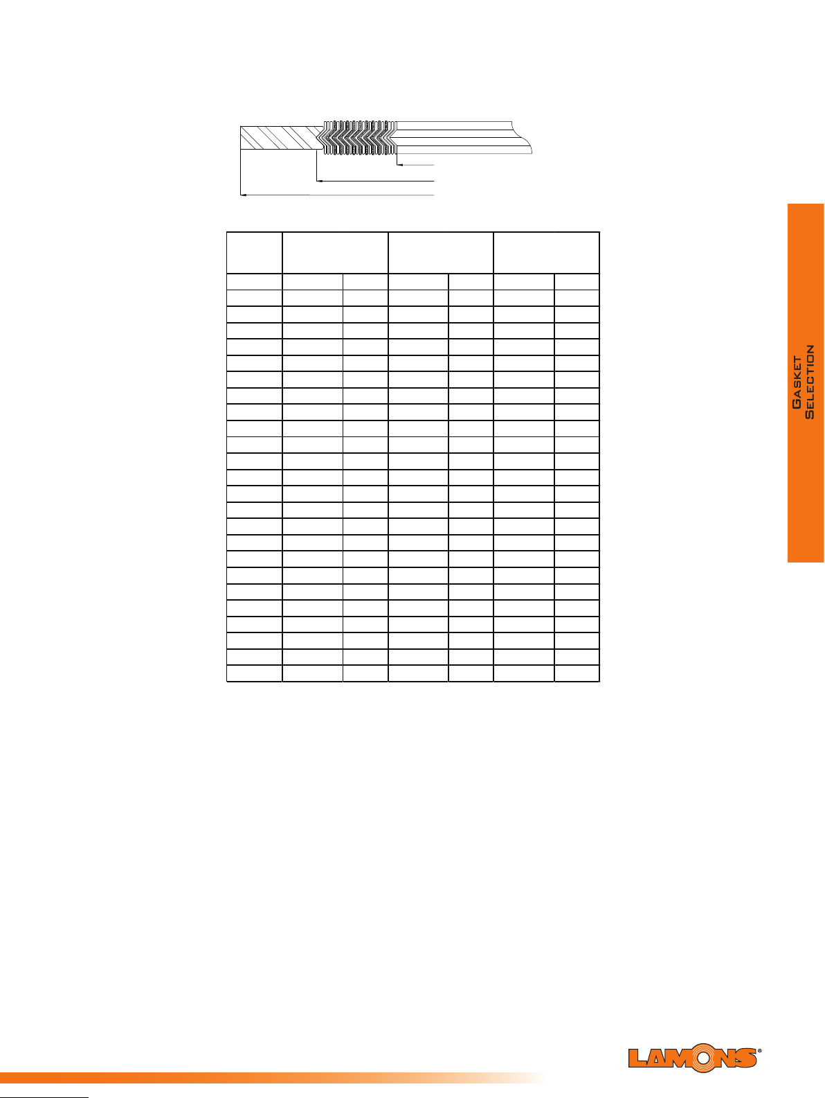
Sealing Global - Servicing Local
Dimensions for Style WR to Suit Japanese (JIS) Flanges
GUIDE RING OUTSIDE DIAMETER (OD)
Pressure Rating 10 kgf/cm
WINDING INSIDE DIAMETER (ID)
WINDING OUTSIDE DIAMETER (OD)
2
DN
10 0.945 24 1.457 37 2.04 7 52
15 1.102 28 1.614 41 2.24 4 57
20 1.339 34 1.850 47 2.44 1 62
25 1.575 40 2.087 53 2.91 3 74
32 2.008 51 2.638 67 3.30 7 84
40 2.244 57 2.874 73 3.50 4 89
50 2.717 69 3.504 89 4.09 4 104
65 3.425 87 4.213 107 4.882 124
80 3.858 98 4.646 118 5.276 134
90 4.331 110 5.118 130 5.669 144
100 4.843 123 5.630 143 6.260 159
125 5.827 148 6.811 173 7.480 190
150 6.850 174 7.835 199 8.661 220
175 7.913 201 8.898 226 9.646 245
200 8.937 227 9.921 252 6.693 170
25 9.921 252 10.906 277 11.4 17 290
2
250 10.945 278 12.205 310 13.071 332
300 12.953 329 14.213 361 14.843 377
350 14.409 366 15.984 406 16.614 422
400 16.417 417 17.992 457 19.055 484
450 18.425 468 20.394 518 21.220 539
500 20.394 518 22.362 568 23.386 594
550 22.402 569 24.370 619 25.591 650
600 24.409 620 26.378 670 27.559 700
Winding Inside
Diameter (ID)
Inches mm Inches mm Inches mm
Winding Outside
Diameter (OD)
Guide Ring Outside
Diameter (OD)
10.629 270
97

Dimensions for Style WR to Suit Japanese (JIS) Flanges
Pressure Rating 16-20 kgf/cm
INNER RING INSIDE DIAMETER (ID)
WINDING INSIDE DIAMETER (ID)
WINDING OUTSIDE DIAMETER (OD)
GUIDE RING OUTSIDE DIAMETER (OD)
2
DN
Inner Ring Inside
Diameter (ID)
Winding Inside
Diameter (ID)
Winding Outside
Diameter (OD)
Guide Ring Outside
Diameter (OD)
Inches mm Inches mm Inches mm Inches mm
10 0.709 18 0.945 24 1.457 37 2.047 52
15 0.866 22 1.102 28 1.614 41 2.244 57
20 1.102 28 1.339 34 1.850 47 2.441 62
25 1.339 34 1.575 40 2.087 53 2.913 74
32 1.693 43 2.008 51 2.638 67 3.307 84
40 1.929 49 2.244 57 2.874 73 3.504 89
50 2.402 61 2.717 69 3.504 89 4.094 104
65 3.031 77 3.425 87 4.213 107 4.882 124
80 3.504 89 3.898 99 4.685 119 5.512 140
90 4.016 102 4.488 114 5.472 139 5.906 150
100 4.528 115 5.000 127 5.984 152 6.496 165
125 5.512 140 5.984 152 6.969 177 7.953 202
150 6.535 166 7.165 182 8.425 214 9.331 237
175 - - - - - - - 200 8.543 217 9.173 233 10.433 265 11.1 02 282
225 - - - - - - - 250 10.551 268 11.339 288 12.913 328 13.937 354
300 12.559 319 13.346 339 14.921 379 15.906 404
350 14.016 356 14.803 376 16.378 416 17.717 450
400 16.024 407 17.008 432 18.976 482 20.000 508
450 18.031 458 19.016 483 20.984 533 22.559 573
500 20.000 508 20.984 533 22.953 583 24.724 628
550 22.008 559 22.992 584 24.961 634 26.929 684
600 24.016 610 25.
000 635 26.969 685 28.898 734
Sealing Global - Servicing Local

Sealing Global - Servicing Local
Dimensions for Style WR to Suit Japanese (JIS) Flanges
Pressure Rating 30 kgf/cm
INNER RING INSIDE DIAMETER (ID)
WINDING INSIDE DIAMETER (ID)
WINDING OUTSIDE DIAMETER (OD)
GUIDE RING OUTSIDE DIAMETER (OD)
2
DN
10 0.709 18 0.945 24 1.457 37 2.323 59
15 0.866 22 1.102 28 1.614 41 2.520 64
20 1.102 28 1.339 34 1.850 47 2.717 69
25 1.339 34 1.575 40 2.087 53 3.110 79
32 1.693 43 2.008 51 2.638 67 3.504 89
40 1.929 49 2.244 57 2.874 73 3.937 100
50 2.402 61 2.717 69 3.504 89 4.488 114
65 2.677 68 3.071 78 3.858 98 5.512 140
80 3.150 80 3.543 90 4.331 110 5.906 150
90 3.622 92 4.016 102 5.000 127 6.378 162
100 4.094 104 4.567 116 5.551 141 6.772 172
125 5.039 128 5.512 140 6.49
150 6.024 153 6.496 165 7.756 197 9.803 249
200 7.953 202 8.583 218 9.843 250 11.575 294
250 9.882 251 10.669 271 12.244 311 14.173 360
300 11.811 300 12.598 320 14.173 360 16.457 418
350 13.228 336 14.016 356 15.591 396 18.228 463
400 15.079 383 15.866 403 17.835 453 20.630 524
Inner Ring Inside
Diameter (ID)
Inches mm Inches mm Inches mm Inches mm
Winding Inside
Diameter (ID)
Winding Outside
Diameter (OD)
6 165 8.150 207
Guide Ring Outside
Diameter (OD)
Dimensions for Style WR to Suit Japanese (JIS) Flanges
Pressure Rating 40 kgf/cm
2
DN
10 0.591 15 0.827 21 1.339 34 2.323 59
15 0.709 18 0.945 24 1.457 37 2.520 64
20 0.906 23 1.142 29 1.654 42 2.717 69
25 1.142 29 1.378 35 1.890 48 3.110 79
32 1.496 38 1.732 44 2.362 60 3.504 89
40 1.693 43 2.008 51 2.638 67 3.937 100
50 2.165 55 2.480 63 3.110 79 4.488 114
65 2.677 68 3.071 78 3.858 98 5.512 140
80 3.150 80 3.543 90 4.331 110 5.906 150
90 3.622 92 4.016 102 5.000 127 6.378 162
100 4.094 104 4.567 116 5.551 141 7.165 182
125 5.039 128 5.512 140 6.49
150 6.024 153 6.496 165 7.756 197 10.433 265
200 7.953 202 8.583 218 9.843 250 12.402 315
250 9.882 251 10.669 271 12.244 311 14.882 378
300 11.811 300 12.598 320 14.173 360 17.087 434
350 13.228 336 14.016 356 15.591 396 18.858 479
400 15.079 383 15.866 403 17.835 453 20.906 531
Inner Ring Inside
Diameter (ID)
Inches mm Inches mm Inches mm Inches mm
Winding Inside
Diameter (ID)
Winding Outside
Diameter (OD)
6 165 8.819 224
Guide Ring Outside
Diameter (OD)
99

Dimensions for Style WR to Suit Japanese (JIS) Flanges
Pressure Rating 63 kgf/cm
INNER RING INSIDE DIAMETER (ID)
WINDING INSIDE DIAMETER (ID)
WINDING OUTSIDE DIAMETER (OD)
GUIDE RING OUTSIDE DIAMETER (OD)
2
DN
Inner Ring Inside
Diameter (ID)
Winding Inside
Diameter (ID)
Winding Outside
Diameter (OD)
Guide Ring Outside
Diameter (OD)
Inches mm Inches mm Inches mm Inches mm
10 0.591 15 0.827 21 1.339 34 2.520 64
15 0.709 18 0.945 24 1.457 37 2.717 69
20 0.906 23 1.142 29 1.654 42 2.953 75
25 1.142 29 1.378 35 1.890 48 3.150 80
32 1.496 38 1.732 44 2.362 60 3.543 90
40 1.693 43 2.008 51 2.638 67 4.213 107
50 2.165 55 2.480 63 3.110 79 4.921 125
65 2.677 68 3.071 78 3.858 98 5.984 152
80 3.150 80 3.543 90 4.331 110 6.378 162
90 3.622 92 4.016 102 5.000 127 7.047 179
100 4.094 104 4.567 116 5.551 141 7.638 194
125 5.039 128 5.512 140 6.496 165 9.252 235
150 6.024 153 6.496 165 7.756 197 10.827 275
200 7.953 202 8.583 218 9.843 250 12.913 328
250 9.882 251 10.669 271 12.244 311 15.512 394
300 11.811 300 12.598 320 14.173 360 17.559 446
350 13.228 336 14.016 356 15.591 396 19.213 488
400 15.079 383 15.866 403 17.835 453 21.457 545
Sealing Global - Servicing Local
 Loading...