


Version 1.1
Lamobo R1(BPI-R1)
User Manual
For more details, please visit LAMOBO.org or LAMOBO.com

Lamobo R1(BPI-R1) User Manual
Version 1.0
1
Table of Contents
Product Introduction ................................................................................................................. 2
Product appearance .................................................................................................................. 3
Specification .............................................................................................................................. 4
Hardware ................................................................................................................................... 5
Hardware connect sketch map .................................................................................................. 7
Use Method (Android or Android-OpenWrt) ............................................................................ 8
Step 1: Get What You Need ....................................................................................................... 8
Step 2: Download The Relevant Image File: .............................................................................. 9
Step 3: Prepare Your SD Card For The Lamobo R1 .................................................................. 10
Step 4: How to write the image to SD card? ........................................................................... 11
Step 5: Set Up Your Lamobo R1 ............................................................................................... 15
Step 6: Shut Down Your Lamobo R1 ........................................................................................ 16
Use Method (OpenWrt) .......................................................................................................... 17
Step 1: Get What You Need ..................................................................................................... 17
Step 2: Download Source Code ............................................................................................... 18
Step 3: Prepare Your SD Card For The Lamobo R1 .................................................................. 18
Step 4: How to build OpenWrt? .............................................................................................. 18
Step 5: How to write bootable OS image/firmware to Micro SD card? .................................. 19
Step 6: Set Up Your Lamobo R1 ............................................................................................... 20
Step 7: Shut Down Your Lamobo R1 ........................................................................................ 20
GPIO Define ............................................................................................................................. 20
R1 PIN Define ........................................................................................................................... 23
R1 UART Define ....................................................................................................................... 26

Lamobo R1(BPI-R1) User Manual
Version 1.0
2
Product Introduction
Lamobo R1 is an open source development platform based on OpenWRT
system, in addition to high specification of 1GHz Cortex A7 dual-core
processor and 1GB large amounts of memory, and Raspberry Pi and
Lamobo R1-compatible GPIO interface, allowing you to easily cut across
different platforms-hwan, and run other systems such as Debian Linux,
Ubuntu Linux, Raspberry Pi and Cubie Unofficial open source systems such
as Board, in order to increase development flexibility. Network online,
Lamobo R1 through BCM53125 efficient routing chip provides five groups
with Gigabit Ethernet ports, and built-in RTL8192cu wireless networking
chipset provides compatible with 802.11b/g/n wireless networking
standards; If use SATA2 hard disk or an external USB storage device and
comply with the cloud platform service provided by Elastos, Allows you to
easily upgrade Lamobo R1 into personal cloud storage device or Internet
Control Center of audio, entertainment and security protection function,
its powerful processing efficiency and high integration degree function
interface, which is able to meet the needs of users in different levels.

Lamobo R1(BPI-R1) User Manual
Version 1.0
3
Product appearance

Lamobo R1(BPI-R1) User Manual
Version 1.0
4
Specification
Hardware specification
CPU
A20 ARM Cortex™-A7 Dual-Core
GPU
ARM Mali400MP2Complies with OpenGL ES 2.0/1.1
Memory (SDRAM)
1GB DDR3 (shared with GPU)
Storage
Micro SD (Max. 64GB) card slot, UP to 2TB on 2.5 SATA disk
Network
Five Gigabit Ethernet ports and WLAN b/g/n (RTL8192cu)
2T2R function
Video Input
One CSI input port allows for the connection of a designed
camera module
Video Outputs
HDMI v1.4, LVDS
Audio Output
Audio Input
3.5 mm audio socket and HDMI
Built-In Microphone
Power Source
5V via Micro USB(DC In Only) or OTG adapter
Buttons
Reset button x1; Power button x1
LED
Power LED(Red) x1; User-defined LED(Green) x1
USB 2.0 Ports
USB 2.0 A type× 1 and USB 2.0 OTG× 1
GPIO(2X13 pin)
GPIO,UART,I2C bus ,SPI bus with two chip selects,
CAN bus, ADC, PWM, +3.3v, +5v, Ground.
Remote
IR
Other
Backup battery socket
Compatible
system
Android 4.2, Raspbian, Lubuntu, OpenSuse, Debian
Product size
148 mm × 100mm
Weight
83g
Lamobo R1(BPI-R1) User Manual
Version 1.0
5
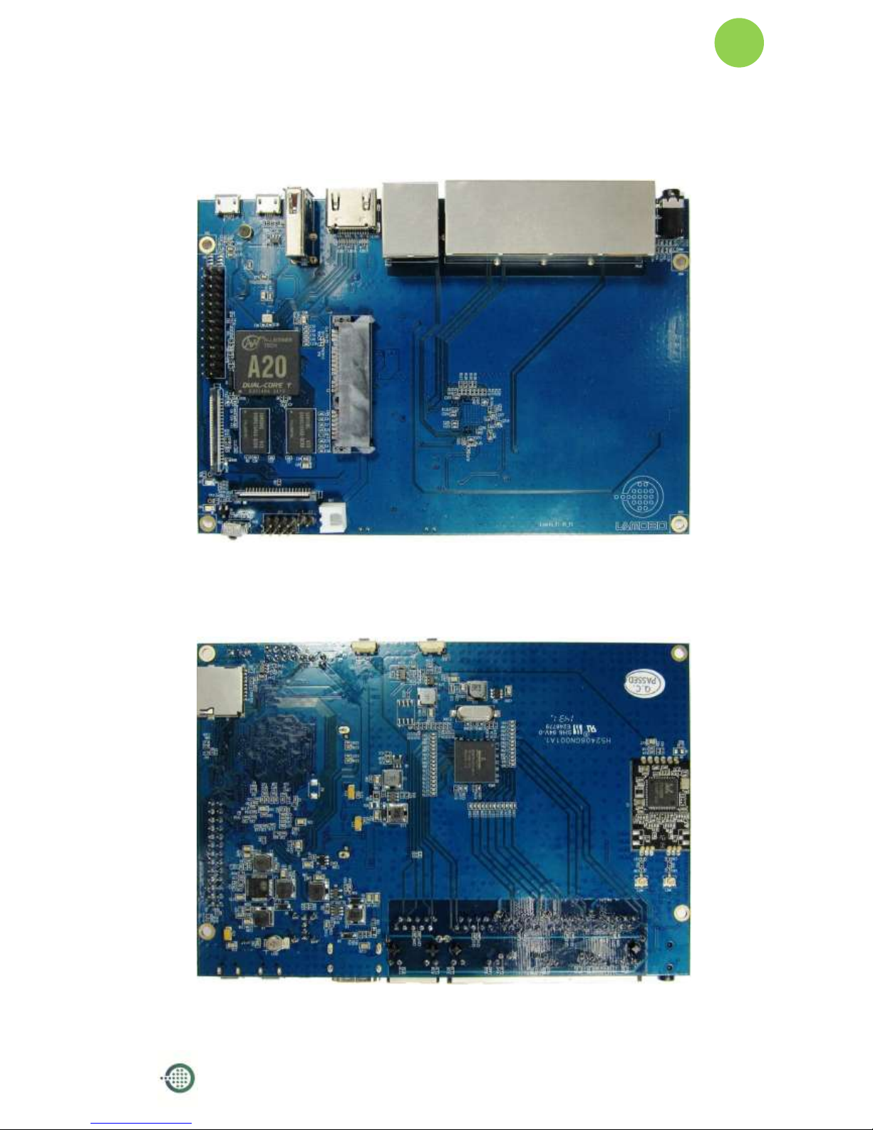
Hardware
· Front:
· Back:

Lamobo R1(BPI-R1) User Manual
Version 1.0
6
· Interface:
(Front Side)
(Back Side)

Lamobo R1(BPI-R1) User Manual
Version 1.0
7
Hardware connect sketch map
(Front Side)
(Back Side)

Lamobo R1(BPI-R1) User Manual
Version 1.0
8
Use Method (Android or Android-OpenWrt)
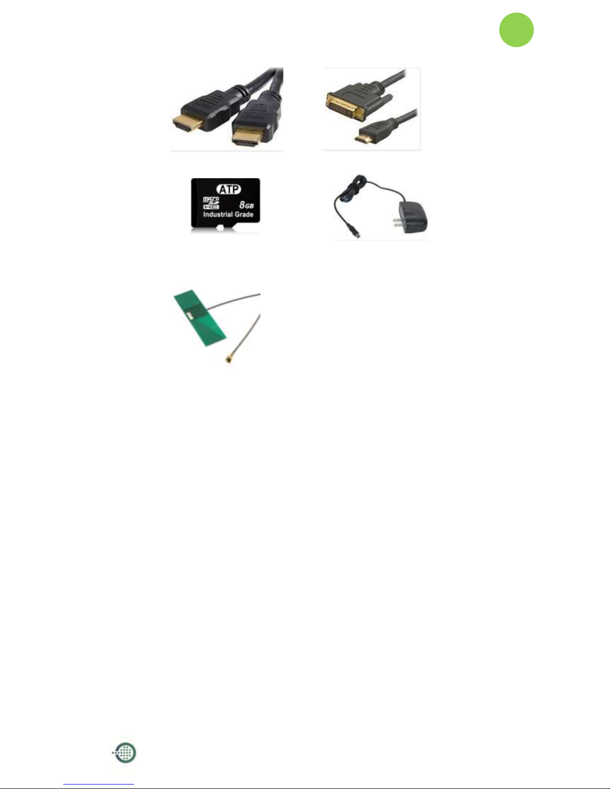
Step 1: Get What You Need
First time to enjoy your Lamobo R1, you need at least the accessories in the table
below.
No.
Item
Minimu recommended specification & notes
1
Micro SD card
Minimum size 8 GB; class 10 (the class indicates how
fast the card is).
We recommend using branded SD cards as they are
more reliable.
2
HDMI(Full sized)
to HDMI / DVI
lead
HDMI to HDMI lead (for HD TVs and monitors with
HDMI input).
OR
HDMI to DVI lead (for monitors with DVI input).
3
Mouse
Any standard USB keyboard and mouse should
work.
Mice or Keyboards that take a lot of power from the
USB ports, however, may need a powered USB hub.
This may include some wireless devices.
4
Ethernet cable
Networking is must of router.
5
Micro USB power
adapter
A good quality, micro USB power supply that can
provide at least 2A at 5Vis essential.
6
Audio lead
(Optional)
You can choose a 3.5mm jack audio lead to connect
to audio port to get stereo audio.
7
Mobile Hard disk
(Optional)
You can choose to connect a mobile hard disk to
SATA port to store more files.
8
Antenna
You can choose two 2.4GHz WIFI antennas to
connect to antenna ports to get advanced wireless
performance.
Lamobo R1(BPI-R1) User Manual
Version 1.0
9
HDMI to HDMI lead
HDMI to DVI lead
Micro SD card
Micro USB power adapter
WiFi antenna
Step 2: Download The Relevant Image File:
Please visit our webmaster: LAMOBO.org or LAMOBO.com to download
image, Lamobo R1 all image can be download from this web.

Lamobo R1(BPI-R1) User Manual
Version 1.0
10
Step 3: Prepare Your SD Card For The Lamobo R1
In order to enjoy your Lamobo R1, you will need to install an Operating System
(OS) onto amicro SD card. Instructions below will teach you how to write an OS
image to your SD card under Windows or Linux.
1. Insert your micro SD card into your computer. The size of SD should be
larger than the OS image size, generally 8GB or greater.
2. Format the SD card.
Windows:
i. Download the a SD card format tool such as SD Formatter from
https://www.sdcard.org/downloads/formatter_4/eula_windows/
ii. Unzip the download file and run the setup.exe to install the tool on
your machine.
iii. In the "Options" menu, set "FORMAT TYPE" option to QUICK,
"FORMAT SIZE ADJUSTMENT" option to "ON".
Lamobo R1(BPI-R1) User Manual
Version 1.0
11
iv. Check that the SD card you inserted matches the one selected by
the Tool.
v. Click the “Format” button.
Linux:
i. Run
fdisk –l
command to check the SD card node.
ii. Run
sudo fdisk /dev/sdx
command to delete all partition of SD
card.
iii. Run
mkfs –t vfat /dev/sdx
command to format the entire SD
card as FAT.
(x should be replaced according to your SD card node)
Step 4: How to write the image to SD card?
1. Insert the SD card to PC.
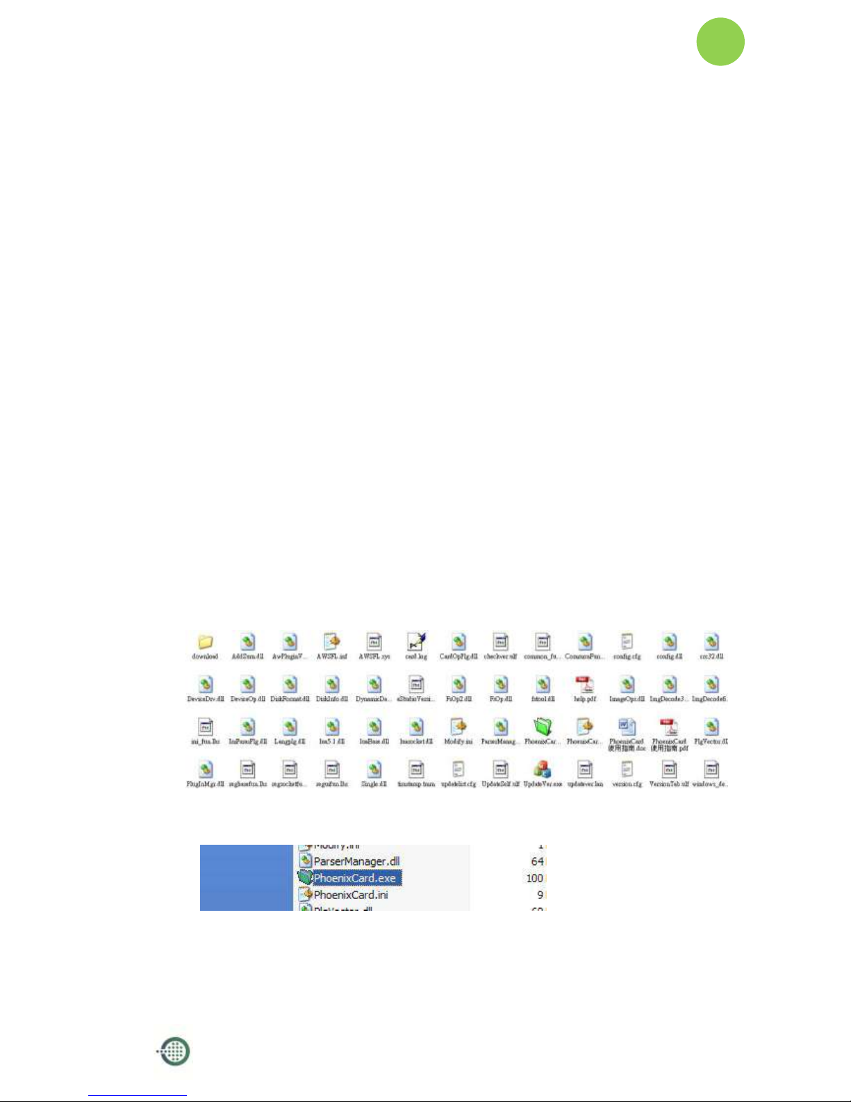
2. Unpack PhoenixCard_V309.rar you received.
3. Decompress it:
i. Run PhoenixCard.exe
Lamobo R1(BPI-R1) User Manual
Version 1.0
12
ii. Press “DiskCheck” and select disk of SD Card.
iii. Press “Img File” and Select system.img
iv. Select “Startup” and press “OK”.

Lamobo R1(BPI-R1) User Manual
Version 1.0
13
v. Press “Burn”.Start upgrading.
vi. Upgraded complete.

Lamobo R1(BPI-R1) User Manual
Version 1.0
14
vii. Press “Exit”
Lamobo R1(BPI-R1) User Manual
Version 1.0
15
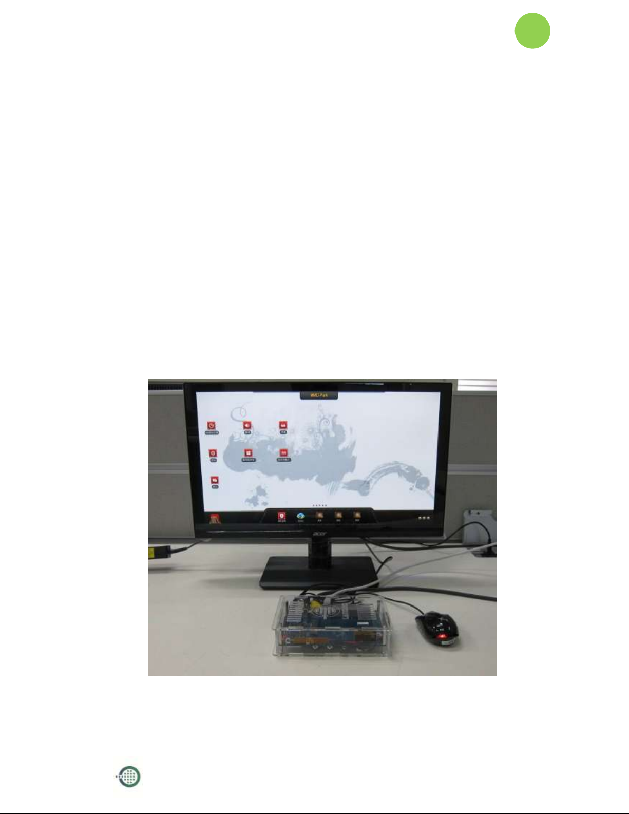
Step 5: Set Up Your Lamobo R1
According to the set up diagram below, you can easily set up your Lamobo R1.
1. Insert the written-image SD card that to the SD card spot on the left side
edge of the underside of the board.
2. The HDMI Type A (Full sized) port is between a USB port and a RJ45 port
of the board. Just connect any HDMI cable from the board to your TV or
HDMI Monitor.
3. Plug a mouse into the USB slot.
4. Plug a Ethernet cable into the RJ45 slot.
5. Finally, at the very left of the bottom edge is the micro-usb power
connector. Plug in a regulated power supply that is rated at 5V ± 2% and
at least 2A.
If all goes well, the R1 will boot in a few minutes. The screen will display
the OS GUI.

Lamobo R1(BPI-R1) User Manual
Version 1.0
16
Step 6: Shut Down Your Lamobo R1
This will shut down the PI safely, (just use the power key to turn off might
damage the SD-cards file system). After that you can press the power key for 5
seconds to turn it off.

Lamobo R1(BPI-R1) User Manual
Version 1.0
17
Use Method (OpenWrt)
Step 1: Get What You Need
First time to enjoy your Lamobo R1, you need at least the accessories in the table
below.
No.
Item
Minimu recommended specification & notes
1
Micro SD card
Minimum size 8 GB; class 10 (the class indicates how
fast the card is).
We recommend using branded SD cards as they are
more reliable.
2
Ethernet cable
Networking is must of router.
3
Micro USB power
adapter
A good quality, micro USB power supply that can
provide at least 2A at 5Vis essential.
4
Audio lead
(Optional)
You can choose a 3.5mm jack audio lead to connect
to audio port to get stereo audio.
5
Mobile Hard disk
(Optional)
You can choose to connect a mobile hard disk to
SATA port to store more files.
6
Antenna
You can choose two 2.4GHz WIFI antennas to
connect to antenna ports to get advanced wireless
performance.
Micro SD card
Micro USB power adapter

Lamobo R1(BPI-R1) User Manual
Version 1.0
18
WiFi antenna
Step 2: Download Source Code
Please visit github.com to download source code, Lamobo R1 source code
can be downloading from this web.
https://github.com/Lamobo/Lamobo-R1-OpenWrt
How to download?
A simple way is using git tools, for instance:
git clone git@github.com:Lamobo/Lamobo-R1-OpenWrt.git
About how to use git tools at github.com, please refer to:
https://help.github.com/articles/set-up-git/
Step 3: Prepare Your SD Card For The Lamobo R1
In order to enjoy your Lamobo R1, you will need to install an Operating System
(OS) onto a micro SD card. Instructions below will teach you how to write an OS
image to your SD card under Windows.
Insert your micro SD card into your computer. The size of SD should be larger
than the OS image size, generally 512MB or greater.
Step 4: How to build OpenWrt?
Step to Build
$ cd Lamobo-R1

Lamobo R1(BPI-R1) User Manual
Version 1.0
19
$ ./scripts/feeds update -a
$ ./scripts/feeds install –a
$ make menuconfig
$ make kernel_menuconfig # optionial
$ make V=s
One-off Build
$ ./misc/build.sh
Step 5: How to write bootable OS image/firmware to Micro SD
card?
Windows
Windows users might want to use Win32 Disk Imager
Download: http://sourceforge.net/projects/win32diskimager/
OS X
1. Download the latest OpenWrt image.
2. Insert your micro-SD card into the Mac or card reader.
3. Identify your micro-SD card device using 'diskutil list' and do a 'diskutil unmountDisk' for the
whole disk device (disk9 for example and not disk9s1):
4. diskutil unmountDisk disk9
5. Write the OpenWrt image to the micro-SD card using ‘sudo dd’ (using the raw device:
In case your micro0SD card is disk9 then use /dev/rdisk9):
$ sudo dd if= openwrt-sunxi-Lamobo-R1-sdcard-vfat-ext4-configured
of=/dev/rdisk9 bs=10m && diskutil eject disk9
Linux

Lamobo R1(BPI-R1) User Manual
Version 1.0
20
Insert your micro-SD card into card reader. Write the OpenWrt image to the
micro-SD card by using ‘sudo dd’:
$ cd openwrt-lamobo-r1/bin/sunxi
$ sudo dd
if=openwrt-sunxi-Lamobo-R1-sdcard-vfat-ext4-configured.img
of=/dev/sdX bs=10MB
[Note]: “/dev/sdX” is the target micro-SD link in Linux host.
Step 6: Set Up Your Lamobo R1
According to the set up diagram below, you can easily set up your Lamobo R1.
1. Insert the written-image SD card that to the SD card spot on the left side
edge of the underside of the board.
2. Plug a mouse into the USB slot.
3. Plug an Ethernet cable into the RJ45 slot.
4. Finally, at the very left of the bottom edge is the micro-usb power
connector. Plug in a regulated power supply that is rated at 5V ± 2% and
at least 2A.
If all goes well, the R1 will boot in a few minutes.
Step 7: Shut Down Your Lamobo R1
This will shut down the PI safely, (just use the power key to turn off might
damage the SD-cards file system). After that you can press the power key for 5
seconds to turn it off.
GPIO Define
We can check R1PINdefinition in this thread, including CON1, CON2, CON3, J12
and J13.
J13 contains the default serial port UART0 (UART0-RX,UART0-TX). UATR0 is

Lamobo R1(BPI-R1) User Manual
Version 1.0
21
configured to be used for console input/output. This is useful if you want to login
using the serial port. So it is the most common used PIN.
J12 also contains serial port.
CON3 contains CAN bus, SPI bus, PWM, serial port and etc. It can be configured
to be used for kinds of peripherals.
CON1 is a CSI camera connector.
CON2 is a DSI display connector.
Pictures and tables below show the specific layout and definition of PIN.

Lamobo R1(BPI-R1) User Manual
Version 1.0
22

Lamobo R1(BPI-R1) User Manual
Version 1.0
23
R1 PIN Define
PIN
PIN define
GPIO
CON1-P01
LINEINL
CON1-P02
LINEINR
CON1-P37
HPL
CON1-P36
HPR
CON1-P07
FMINL
CON1-P09
FMINR
CON1-P04
ADC_X1
CON1-P06
ADC_X2
CON1-P08
ADC_Y1
CON1-P10
ADC_Y2
CON1-P13
LRADC0
CON1-P15
LRADC1
CON1-P33
RESET#
CON1-P17
CSI0-D0
PE4
CON1-P19
CSI0-D1
PE5
CON1-P21
CSI0-D2
PE6
CON1-P23
CSI0-D3
PE7
CON1-P25
CSI0-D4
PE8
CON1-P27
CSI0-D5
PE9
CON1-P29
CSI0-D6
PE10
CON1-P31
CSI0-D7
PE11
CON1-P20
CSI0-PCLK
PE0
CON1-P24
CSI0-MCLK
PE1
CON1-P28
CSI0-VSYNC
PE3
CON1-P30
CSI0-HSYNC
PE2
CON1-P18
CSI0-STBY-EN
PH19
CON1-P26
CSI0-RESET#
PH14
CON1-P32
CSI1-STBY-EN
PH18
CON1-P34
CSI1-RESET#
PH13
CON1-P14
TWI1-SDA
PB19
CON1-P16
TWI1-SCK
PB18
CON1-P12
CSI0-FLASH
PH17
CON1-P22
CSI0-PWR-EN
PH16
CON1-P35
CSI-IO0
PH11
CON1-P38
IPSOUT
CON1-P40
IPSOUT
CON1-P05
GND
CON1-P11
GND
CON1-P39
GND
CON1-P03
VCC-CSI

Lamobo R1(BPI-R1) User Manual
Version 1.0
24
CON2-P09
LCD0-D00
PD0
CON2-P11
LCD0-D01
PD1
CON2-P13
LCD0-D02
PD2
CON2-P15
LCD0-D03
PD3
CON2-P17
LCD0-D04
PD4
CON2-P19
LCD0-D05
PD5
CON2-P21
LCD0-D06
PD6
CON2-P23
LCD0-D07
PD7
CON2-P25
LCD0-D08
PD8
CON2-P27
LCD0-D09
PD9
CON2-P29
LCD0-D10
PD10
CON2-P31
LCD0-D11
PD11
CON2-P33
LCD0-D12
PD12
CON2-P35
LCD0-D13
PD13
CON2-P37
LCD0-D14
PD14
CON2-P39
LCD0-D15
PD15
CON2-P40
LCD0-D16
PD16
CON2-P38
LCD0-D17
PD17
CON2-P36
LCD0-D18
PD18
CON2-P34
LCD0-D19
PD19
CON2-P32
LCD0-D20
PD20
CON2-P30
LCD0-D21
PD21
CON2-P28
LCD0-D22
PD22
CON2-P26
LCD0-D23
PD23
CON2-P22
LCD0-CLK
PD24
CON2-P20
LCD0-CS
PH6
CON2-P18
LCD0-HSYNC
PD26
CON2-P16
LCD0-VSYNC
PD27
CON2-P14
LCD0-DE
PD25
CON2-P12
LCD0-IO2
PH9
CON2-P10
PWM0
PB2
CON2-P08
LCD0-IO1
PH8
CON2-P06
LCD0-IO0
PH7
CON2-P04
TWI3-SCK
PI0
CON2-P02
TWI3-SDA
PI1
CON2-P01
IPSOUT
CON2-P03
IPSOUT
CON2-P05
GND
CON2-P24
GND
CON2-P07
VCC-3V3
CON3-P18
CAN_RX
PH21
CON3-P16
CAN_TX
PH20

Lamobo R1(BPI-R1) User Manual
Version 1.0
25
CON3-P23
SPI0_CLK
PI11
CON3-P21
SPI0_MISO
PI13
CON3-P19
SPI0_MOSI
PI12
CON3-P24
SPI0_CS0
PI10
CON3-P26
SPI0_CS1
PI14
CON3-P05
TWI2-SCK
PB20
CON3-P03
TWI2-SDA
PB21
CON3-P15
UART2_CTS
PI17
CON3-P22
UART2_RTS
PI16
CON3-P11
UART2_RX
PI19
CON3-P13
UART2_TX
PI18
CON3-P10
UART3_RX
PH1
CON3-P08
UART3_TX
PH0
CON3-P12
PH2
PH2
CON3-P07
PWM1
PI3
CON3-P01
VCC-3V3
CON3-P17
VCC-3V3
CON3-P02
VCC-5V
CON3-P04
VCC-5V
CON3-P09
GND
CON3-P25
GND
CON3-P06
GND
CON3-P14
GND
CON3-P20
GND
J12-P03
PH5
PH5
J12-P05
PH3
PH3
J12-P04
UART7_RX
PI21
J12-P06
UART7_TX
PI20
J12-P01
VCC-5V
J12-P02
VCC-3V3
J12-P07
GND
J12-P08
GND
J13-P01
UART0-RX
PB23
J13-P02
UART0-TX
PB22

Lamobo R1(BPI-R1) User Manual
Version 1.0
26
R1 UART Define

Lamobo R1(BPI-R1) User Manual
Version 1.0
27
This equipment has been tested and found to comply with the limits for a Class B digital
device, pursuant to part 15 of the FCC Rules. These limits are designed to provide
reasonable protection against harmful interference in a residential installation. This
equipment generates, uses and can radiate radio frequency energy and, if not installed
and used in accordance with the instructions, may cause harmful interference to radio
communications. However, there is no guarantee that interference will not occur in a
particular installation. If this equipment does cause harmful interference to radio or
television reception, which can be determined by turning the equipment off and on,
the user is encouraged to try to correct the interference by one or more of the
following measures:
• Reorient or relocate the receiving antenna.
• Increase the separation between the equipment and receiver.
• Connect the equipment into an outlet on a circuit different from that to which the
receiver is connected.
• Consult the dealer or an experienced radio/TV technician for help.
Caution: Any changes or modifications to this device not explicitly approved by
manufacturer could void your authority to operate this equipment.
This device complies with part 15 of the FCC Rules. Operation is subject to the following
two conditions: (1) This device may not cause harmful interference, and (2) this device
must accept any interference received, including interference that may cause undesired
operation.
This equipment complies with FCC radiation exposure limits set forth for an
uncontrolled environment. This equipment should be installed and operated with
minimum distance 20cm between the radiator & your body
 Loading...