

Lamina Titan White Developer, Titan Series Kit Manual
titaN
tM
series
DescriPtioN
Project:
yPe:
t
oltage:
V
otes:
N
Kit coNteNts
2
6
5
4
Overall Case Size - 12” x 9” x 3”
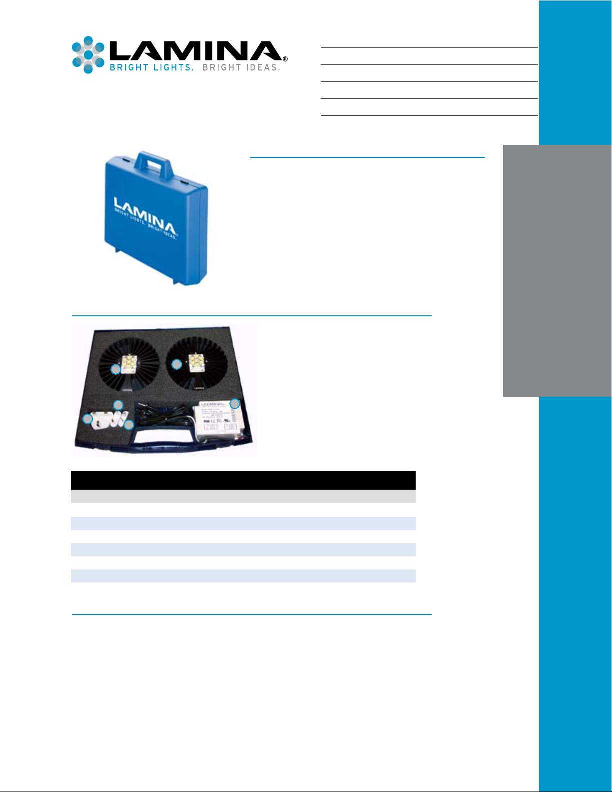
The Titan Warm White & Daylight White Developer Kit enables users to
quickly discover the world of solid state lighting and realize the power
of Lamina’s super-bright LED light engines. This kit is intended for the
rapid evaluation and prototyping of LED lighting solutions. It comes fully
assembled and includes everything needed to jump start your design
efforts. As shown in the Developer Kit contents table and photo, this
comprehensive kit includes two white light engines, a commercially
available LED constant current driver, and prewired DC connections.
3
1
Figure 1
TiTan
TM
WhiTe Developer KiT
Titan Warm White & Daylight White Developer Kit (DK-05D0-0399)
Item Description Qty. P/N Notes
1 Driver Sub-Assembly, 1050mA 1 160-0251 Philhong PSA60W-240
2 Light Source and Heat Sink, 3050K Warm White 1 160-0248 N/A
3 Light Source and Heat Sink, 4700K Daylight White 1 210-0249 N/A
4 Plug Adapter, AC, China/ANZAC 1 210-0134 Franzus NW-12C
5 Plug Adapter, AC, UK 1 210-0135 Franzus NW-135C
6 Plug Adapter, AC, Europe 1 210-0133 Franzus NW-1C
oPeratiNg iNstructioNs
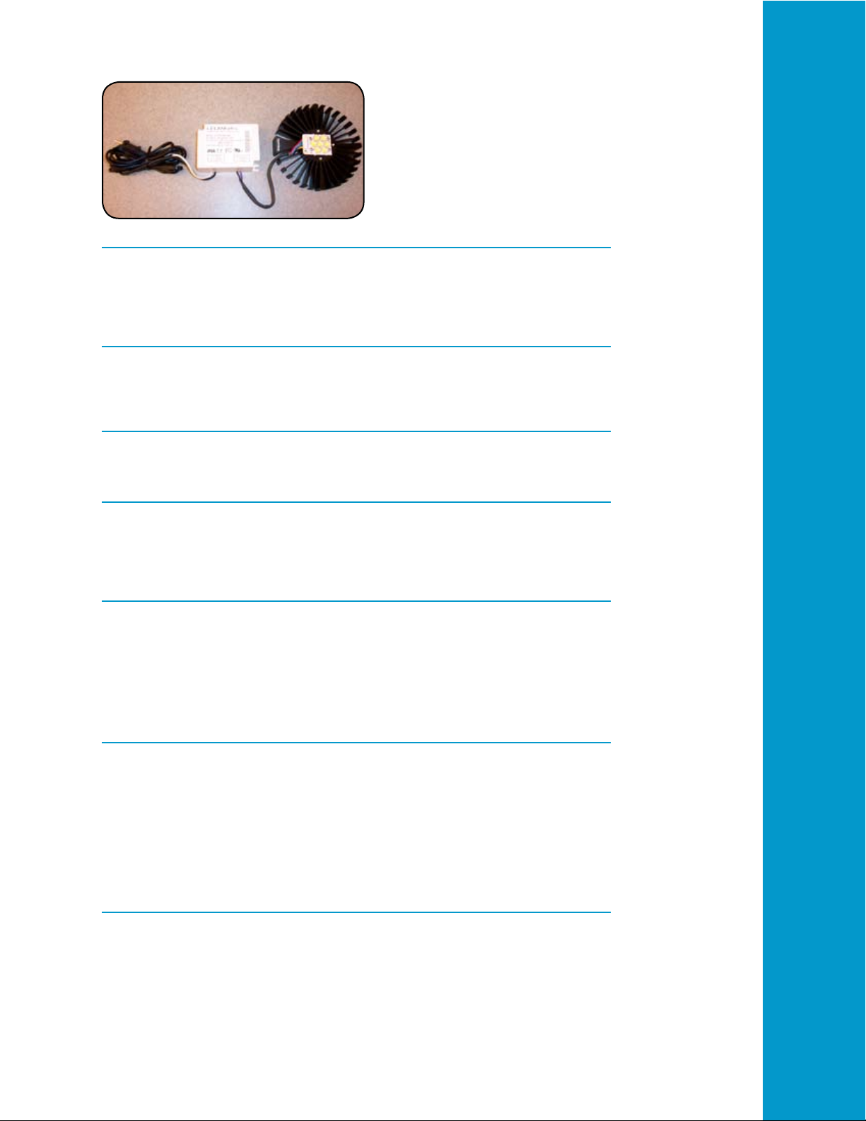
1. Remove the white light engine assembly and driver from the kit case and place them on a suitable
work surface near an AC power outlet. Please verify the DC/DC connection cable is correctly attached
between the light engine and driver.
2.
CAUTION. Lamina LED light sources are extremely bright! Before applying power, direct the light
source away from your eyes or wear suitable protective eye wear. Plug the AC adapter’s power cord
into a 100-240 VAC/50-60 Hz power outlet using the adapter plugs if required. The light source will now
illuminate.
NOTE: Please unplug the AC power before connecting or disconnecting the LED light engine to avoid
potential damage to the light engine or the driver.
120 Hancock Lane | Westampton, NJ 08060 | USA | laminalighting.com | T +1 609.265.1401 | TF + 1 800.808.5822
©2008 Lamina Lighting Inc. FM-0176 Rev 03.11.08
coNNectiNg two laMiNa titaN light eNgiNe asseMbies
Figure 2
attachiNg to your Fixture or asseMbly
The white light engine assembly can be mounted in several congurations. Ideally, the light engine should be
congured horizontally, thereby allowing air to ow through the vertically oriented ns. Alternate assembly
positions are also possible. The orientation of the ns and the surrounding environment will determine how
efciently the heat sink can dissipate the thermal energy.
haNDliNg PrecautioN
Contact with the silicone based encapsulant on the surface of the light engine must be avoided to prevent
damage. Do not apply pressure to the silicone based encapsulant or allow it to come into contact with sharp
objects. Lamina LED light engines must be handled from the sides.
Further PrototyPiNg iNForMatioN aND suPPort
Additional information regarding the Titan Series of light engines, optics, heat sinks, accessories, developer kits,
compatible drivers, and applications notes can be found by visiting Lamina’s website.
electrical coNNectioNs
When using constant current LED drivers with high compliance voltage (Advance, LED Works, etc. or a custom
driver) the output of the supply must be connected to the part before power is applied to the input of the supply.
For more information refer to Lamina’s connection application note #AN-06 which can be found on the Lamina
website.
asseMbly recoMMeNDatioNs
Titan Series light engines are designed for attachment to a heat sink with conductive epoxy, or screw down for
ange mount devices with thermal grease in the joint. For attachment using screws a 4-40 UNC round head
or metric equivalent M3 x 0.5 cheese head screw, 18-8 SS is recommended. When mounting the light engine,
position the four screws in the center of each of the four slots. Tighten the four screws evenly, rst to about
0.89 inch pounds (56 Newton-centimeters), and then tighten each to a maximum torque of 5 inch pounds (45
Newton-centimeter). Flatness requirement of the surface that the light engine is mounted to is 0.001 inch/inch
(1mm/meter). To prevent damage when using conductive epoxy do not use mounting screws.
Notes
1. This product uses silicone materials for superior optical performance. Do not expose the part to uids that
may react with silicone compounds. See DOW Chemical Form 45-0113D-01, Silicone Fluid Resistance
Guide.
2.
Ray trace models are available upon request.
3. Lamina may make process or materials changes affecting the performance or other characteristics of our
products. These products supplied after such changes will continue to meet published specications, but
may not be identical to product supplied as samples or under prior orders.
warraNty
Lamina (Seller) extends warranty on goods produced by the Seller for one (1) year from original date of shipment,
that the goods sold hereunder are new and free from substantive defects in workmanship and materials. This
warranty extends only to the Buyer and not to indirect purchasers or users. Seller’s liability under the foregoing
warranty is limited to replacement of goods or repair of defects or refund of the purchase price at the seller’s sole
option. The above warranty does not apply to defects resulting from the improper or inadequate maintenance,
unauthorized modication, improper use or operation outside of Seller’s specications for the product, abuse,
neglect or accident.
THE ABOVE WARRANTY IS EXCLUSIVE AND NO OTHER WARRANTY, WHETHER WRITTEN OR ORAL,
IS EXPRESSED OR IMPLIED. LAMINA SPECIFICALLY DISCLAIMS THE IMPLIED WARRANTIES OF
©2008 Lamina Lighting Inc. FM-0176 Rev 03.11.08
 Loading...