

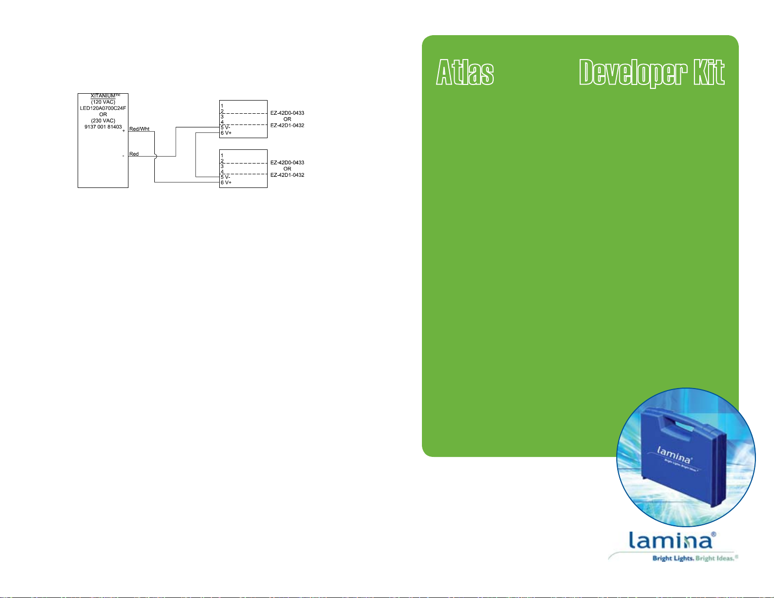
construct the cable is to cut the two spare cables in half and stripping the wire lead ends
about 3/8” (9mm) on three of the halves. Plug the connectors of these three cable halves into
the driver and each light engine assembly. Finally, connect the stripped leads as indicated
in Figure 4.
Connecting Two Lamina AtlasTM White Light Engine Assemblies
Figure 4.
Electrical Connections
When using constant current LED drivers with high compliance voltage (Advance, LED Works,
etc. or a custom driver) the output of the supply must be connected to the part before power is
applied to the input of the supply. For more information refer to Lamina’s connection application
note which can be found on the website at www.laminalighting.com.
Assembly Recommendations
Lamina’s AtlasTM Series Light Engines are designed for attachment to a heat sink with
conductive epoxy, or screw down for ange mount devices with thermal grease in the joint. For
attachment using screws a 4-40 UNC round head or metric equivalent M3 x 0.5 cheese head
screw, 18-8 SS is recommended. When mounting the light engine, position the four screws in
the center of each of the four slots. Tighten the four screws eventually, rst to about 0.89 inch
pounds (56 Newton-centimeters), and then tighten each to a maximum torque of 5 inch pounds
(45 Newton-centimeter). Flatness requirement of the surface that the light engine is mounted
to is 0.001 inch/inch (1mm/meter). To prevent damage when using conductive epoxy do not
use mounting screws.
Notes
1. This product uses silicone materials for superior optical performance. Do not expose the
part to uids that may react with silicone compounds. See Dow Chemical Form 45-0113D-
01, Silicone Fluid Resistance Guide.
2. Ray trace models are available upon request.
3. Lamina may make process or materials changes affecting the performance or other
characteristics of our products. These products supplied after such changes will continue
to meet published specications, but may not be identical to product supplied as samples
or under prior orders.
Warranty Statement
Lamina (Seller) extends warranty on goods produced by the Seller for one (1) year from original
date of shipment, that the goods sold hereunder are new and free from substantive defects
in workmanship and materials. This warranty extends only to the Buyer and not to indirect
purchasers or users. Seller’s liability under the foregoing warranty is limited to replacement of
goods or repair of defects or refund of the purchase price at the seller’s sole option. The above
warranty does not apply to defects resulting from the improper or inadequate maintenance,
unauthorized modication, improper use or operation outside of Seller’s specications for the
product, abuse, neglect or accident.
THE ABOVE WARRANTY IS EXCLUSIVE AND NO OTHER WARRANTY, WHETHER
WRITTEN OR ORAL, IS EXPRESSED OR IMPLIED. LAMINA SPECIFICALLY DISCLAIMS
THE IMPLIED WARRANTIES OF MERCHANTABILITY AND FITNESS FOR A PARTICULAR
PURPOSE.
Patents
Lamina’s light engines may be covered by pending patents and/or one or more of the following
U.S. and/or International patents 5876536, 6709749 B, 595880, 6017642, 5565262, 5681444, 5653834, 5581876,
5847935, 5514451, 5747931, 5925203, 5725808, 5929510, 5858145, 5866240, 5953203, 6055151, 614076, 6011330,
6399230, 6914501, 6168490, 6191934, 614075, 6160469, 6300267, 6471805, 6518502, 6739047, 6720859, 6759940,
6518502, 6670856 B1, 6720859, 6713862 B2, WO 00/47399, WO 00/26152, WO 98/19339, 5082804, ZL99808762.9,
69623930, 69628549, 69629572, 805785, 69628549, 843621, 932500, 805785, 812258, 843621, 932500, 805785, 812258,
843621, 932500, 805785, 812258, 843621, 932500, 3327556, 3267299, 3226281, 3405545, 320630, 295695, 284068,
546471, 805785, 812258, 843621, 6455930, 6759940, 6713862, 7,095,053, 7,098,483.
©2007 Lamina AtlasTM, White Developer Kit FM-0174) Rev. 04.09.07
AtlasTM White Developer Kit
Bright.
Compact.
Reliable.
At Lamina we’re changing the way you think
about designing with LEDs.
120 Hancock Lane • Westampton, NJ 08060
609.265.1401 • 800.808.5822
AtlasTM, NT-4000 White Developer Kits
Lamina’s NEW AtlasTM, White Developer Kit series enable users to quickly discover the world
of solid state lighting and realize the power of Lamina’s super-bright LED light engines. This
kit is intended for the rapid evaluation and prototyping of LED lighting solutions based on the
Lamina Warm White or Daylight White light engines. The kit is fully assembled and includes
everything needed to jump start your design efforts. This comprehensive kit includes Warm
White and Daylight White light engine Assemblies, wide and medium optics, a matched,
commercially available, constant current driver prewired with AC and DC connections, AC
plug adaptors and extra DC connectors.
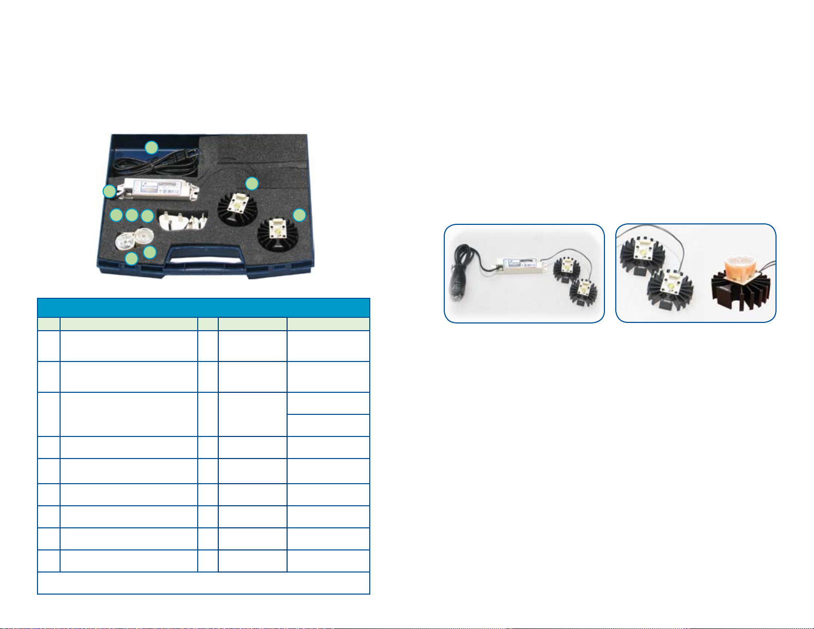
4
Figure 1.
3
8
7
9
6
5
Overall Case Size - 12” x 9” x 3”
1
2
Operating Instructions
1. Remove the Warm White light engine assembly and driver from the kit case and place
them on a suitable work surface near an AC power outlet. Please verify the DC/DC
connection cable is correctly attached between the light engine and driver. Also, verify
the AC power cord is properly connected to the driver.
2. CAUTION: Lamina LED Light Engines are extremely BRIGHT! Apply power directly
to the light engine with it pointing away from your eyes, or wear suitable protective
eyewear. Plug the driver’s AC power cord into a 120VAC/60Hz power outlet (230 VAC/
50HZ) depending on model selection.
3. To test the included optics, insert the legs of the optic holder into the four corner holes
in Lamina’s EZ Connect board. The EZ Connect board is designed to align the optic to
the center of the light engine and allow the optic to rest on the light engine surface.
4. To apply power to the Daylight White light engine assembly, unplug the AC power and
detach the DC/DC connection cable from the Warm White Assembly. Plug the DC
connection cable into the Daylight White Assembly then replug the AC cord.
NOTE: Please unplug the AC power before connecting or disconnecting the LED Light
Engine to avoid potential damage to the Light Engine or the driver.
Optic Placed on Light
Engine Assembly
AtlasTM, NT-4000 White Developer Kit - DK-04D0-0394 and DK-04D0-0395
Item Description Qty. P/N Notes
Light Engine Assembly - Warm White
1
Light Source Soldered to EZ Connect
with Heat Sink
Light Engine Assembly - Daylight White
2
Light Source Soldered to EZ Connect
with Heat Sink
Driver Sub Assembly, Advance 700mA
3
DC/DC Cable Assembly, 2-pin, 200mm
4
(1 prewired, 2 spare)
Medium Optic, Secondary, NT-4000, 30º
5
Beam Angle
Wide Optic, Secondary, NT-4000, 45º
6
Beam Angle
Plug Adapter, AC, UK, Polarized,
7
Ungrounded
Plug Adapter, AC, China/ANZAC, 230
8
VAC
Plug Adapter, AC, Europe, Polarized,
9
Ungrounded
*DK-04D0-0394 is congured with 160-0213 - 120 VAC Driver; DK-04D0-0395 is congured with
160-0214 - 230 VAC Driver
1 160-0245 N/A
1 160-0244
160-0213*
1
160-0214*
3 210-0145 TYCO/AMP 1365323-1
1 OP-4FM1-0442 N/A
1 OP-4FW1-0441 N/A
1 210-0135 Franzus NW-135C
1 210-0134 Franzus NW-2C
1 210-0133 Franzus NW-1C
LEDynamics
0416-Box-32-D-E-350
PHILIPS ADVANCE
LED 120 A0700C24F
PHILIPS (ADVANCE)
9137 001 81403
DC Connection Between Light Engine and Driver
Figure 2.
DC Connection between Light Engine and Driver
The DC connection between the light engine and the driver is shown in Figure 2. Although
the DC/DC connection cable is keyed to facilitate correct attachment to the light engine
assembly, two connection orientations are possible. The proper connection is to terminals 5
and 6 of the EZ Connect Board; this is the side opposite from the dot indicating terminal 1.
If the cable is improperly connected to terminals 1 and 2 of the EZ Connect Board, the light
engine cannot be powered, but this should not result in damage to the light engine. Two
spare DC/DC connection cables are included for prototyping.
Attaching to your Fixture or Assembly
The light engine assembly can be mounted in several congurations. Ideally, the light engine
should be congured horizontally, thereby allowing the heat to radiate through the vertically
oriented ns. Alternate assembly positions are also possible. The orientation of the ns will
determine how efciently the heat sink can dissipate the thermal energy.
Handling Precaution
Contact with the silicone based encapsulated on the surface of the light engine must be
avoided to prevent damage. Do not apply pressure to the silicone based encapsulant or
allow it to come into contact with sharp objects. Lamina LED light engines must be handled
from the sides.
Further Prototyping Information and Support
Additional information regarding the AtlasTM series of light engines, optics, heat sinks,
accessories, developer kits, compatible drivers, and applications notes can be found by
visiting Lamina’s website.
Conguration options with AtlasTM White Light Engines
Both AtlasTM White light engines can be connected in series and driven simultaneously using
the included 700mA 17W constant current driver. This is useful for a side by side comparison
Figure 3.
of the light properties of the AtlasTM Warm White and Daylight White light engines. Two spare
DC connection cables are provided to construct a cable for this purpose. A simple way to
www.la minalighting.com
 Loading...