

"SMART HOME" CONTROL PACKAGE
OPERATING MANUAL
Serving the customer is our first priority
Customized
Intelligence

2
This document contains the technical data
of the Smart Home Control and describes
the installation and handling of the system
during operation.
The complete manual can be found in the
Downloads menu section on www.lamilux.
com.
Installation, checking, commission-
ing and troubleshooting of the device must be carried out by a qualified electrician only (according to
VDE 0100).
This document is subject to change and
will be adapted to later software versions.
The revision number (software version
and date) can be found in the footer.
If you have a device with a later software
version, please check the “Downloads”
menu section on www.lamilux.com, to see if
a recent version of the manual is available.
EXPLANATION OF SYMBOLS
Safety information
Safety instructions for work-
ing on electrical connections,
components etc.
DANGER! ... indicates an imminently
hazardous situation that will
result in death or serious injury if not avoided.
WARNING! ... indicates an imminently
hazardous situation that can
result in death or serious
injury if not avoided.
CAUTION! ... indicates a potentially
hazardous situation that can
result in minor to moderate
injury if not avoided.
... indicates a hazard that
can lead to damaged property if it is not avoided.
STOP
ATTENTION!
Smart Home Control • Revision: 11-05-2016. • As of version 1.7 Subject to technical modifications and errors.

TABLE OF CONTENTS
1. APPLICATION AND FUNCTIONS PAGE 4
2. SCOPE OF SUPPLY PAGE 5
3. TECHNICAL DATA PAGE 6
3.1. Display
3.2. Connection unit
3.3. Weather station
4. INSTALLATION/ASSEMBLY PAGE 8
4.1. Notes on installation
4.2. Notes on wireless equipment
4.3. Installing the display
4.3.1 Installation location and preparation
4.3.2 Wall mount installation
4.3.3
Drilling plan
4.3.4 Removing the wall mount
4.3.5 Instructions for installation and
getting started
4.4. Installing the weather station
4.4.1 Installation location
4.4.2 Design of the device
4.4.3
Installation preparation
4.4.4 Attaching the base
and bracket
4.4.5 Connection
4.4.6 Completing the installation work
4.4.7 Instructions for installation and
getting started
4.5. Installing the connection unit
4.5.1 Connection
4.5.2 Overview of connections
4.5.3
Instructions for installation and
getting started
5. OPERATING THE DISPLAY PAGE 16
5.1. Charging the battery
5.2. Care and maintenance
5.3. Display and control options
on the home screen
5.3.1 Meaning of function
icons (automatic status)
5.4. Audio signals
5.5. Error messages
5.6.
Table: memory capacity of outputs and inputs
6. GETTING STARTED PAGE 24
6.1. Short setup
7. OPERATING THE WEATHER STATION PAGE 28
7.1. Maintenance of the weather station
8. WLAN MODULE PAGE 28
8.1. Description
8.1.1 Scope of supply
8.1.2 Technical data
8.2. Notes on getting started
8.2.1 Notes on installation
8.2.2 Requirements
8.2.3 Notes on wireless equipment
8.2.4 Instructions for installation and
getting started
8.3. Setting up modules, WiFi, App
8.3.1 Installing the app
8.3.2 Starting up the WiFi module
8.3.3 Configuring WiFi
8.3.4 Connecting to the Smart Home
Control
8.3.5 Resetting the WiFi module to the
factory settings
8.4. Using the app
8.4.1 Overview
8.4.2
Control and display page of the app
8.4.2.1 Operating drives and devices,
displaying indoor sensor
values
9. WIRING LAYOUT PAGE 34
10. CONNECTOR PAGE 35
3
Smart Home Control • Revision: 11-05-2016. • As of version 1.7 Subject to technical modifications and errors.

1. APPLICATION AND FUNCTIONS
The Smart Home Control enables easy man-
ual operation of drives and consumers via
the touch display. Drives and consumers are
connected to the terminal unit of the base
set. Optionally up to ten additional drives or
consumers can be connected wirelessly.
A weather station can also be connected to
the terminal unit, thus allowing for automatic
control. The indoor data of the display and
the external data of the weather station are
used for automatic control. This means that
the time, indoor temperature, outdoor temperature, lighting conditions, position of the
sun, wind speed and precipitation messages
can be considered. Additional interior sensors can be integrated into the system via
wireless inputs.
• Automatic shading controls blinds,
awnings and shutters to reflect the lighting conditions, taking into account the
direction of the sun, defined move delays, temperature locks, wind, rain and
frost alarms, the move position, time
and night functions.
• Ventilation control actuates sash and
sliding windows as a function of the indoor temperature. Outdoor temperature
locks like wind, rain and frost alarms,
move positions and time functions are
considered here.
• Automatic lighting control switches
lamps to reflect the outside lighting con
ditions (day/night) and time. If dimming
modules are used, then the dimming lev
el (brightness of the lamp) is considered.
• The heating control system actuates a
one- or two-stage heating system as a
function of the indoor temperature, taking into account day and night (timer);
it has a timer switch for manual heating
during night operation.
• Automatic gutter control actuates a
heater in a specific outdoor temperature range.
• A daily automatic reset and an automatic reset – a short time after a manual
operation – can be set for all outputs.
FUNCTIONS AND PROPERTIES OF THE DISPLAY:
The general accident prevention regulations
for power-operated windows, doors and
gates, and the VDE installation regulations
(or equivalent) must be complied with.
• Control unit with monochrome touch
display and internal temperature sensor
• Built-in rechargeable battery with USB
charging socket
• The display has a wall mount, but can
also be used like a remote control
• Up to 4 displays can be used in the system
FUNCTIONS AND FEATURES
OF THE TERMINAL UNIT:
• Connection for the weather station
• Wired outputs for two 230-V motors,
one 24-V motor and one LED Strip Powerbox (Accessories)
• Wireless communication with up to 10
drives/consumers via Elsner RF wireless actuators
4
Smart Home Control • Revision: 11-05-2016. • As of version 1.7 Subject to technical modifications and errors.

2. SCOPE OF SUPPLY
• Basic set 303 471 with display including USB connection cable 0.5 m (USB
A connector to USB B micro connector)
and terminal unit including connectors
• Weather station 303473
5
Smart Home Control • Revision: 11-05-2016. • As of version 1.7 Subject to technical modifications and errors.
• Wireless communication with up to 32
Elsner RF control devices/sensors
• WiFi integration (for app usage) via optional WiFi module
FUNCTIONS AND PROPERTIES OF THE WEATHER
STATION:
• Brightness measurement (1 sunlight sensor)
• Temperature measurement
• Wind speed measurement
• Precipitation sensing
• GPS receiver for date/time and installation coordinates (for computing the sun
position)
COMPATIBLE WIRELESS ACTUATORS FOR THE
SYSTEM:
• Motorised control units RF-MSG-ST,
RF-MSG, RF-MSG-PF (as of version 3.7
in all cases) for shading window drives.
A group control relay can be used to
connect several drives to one RF-MSG
if needed
• Switching Relay RF Relay ST, RF Relay UP (both as of version 5.5) for consumers such as lights and single-stage
heating
• Dimmers RF-L UN-ST, RF-L LED-ST (as
of version 1.4 in each case), RF-L-UP
1-10 V (as of version 1.1) for dimmable
lamps
• Heating module RF-HE-ST (as of version
5) for two-stage heating
All wireless actuators as of date of
manufacture 14-01-2016 are compatible
with the system. The production date can
be read off the serial number of the device;
it follows a pattern of "DDMMYY serial
number".
COMPATIBLE OPERATING UNITS AND SENSORS FOR
THE SYSTEM:
• Remote control Remo 8 (as of version 1.8)
• Sensor Corlo P2 RF (as of version 1.0)
• Sensor on the RF-B2-UP interface (as of
version 1.0)
• Temperature sensor WGT (as of version
1.0)
• Sensors WG AQS/TH-UP (as of version
1.0) and WGTH-UP (as of version 1.3)
for temperature measurement (moisture
and CO2 measurement of the sensors is
not evaluated)

6
3. TECHNICAL DATA
3.1. DISPLAY
The product complies with the provisions of
EU directives.
3.2. CONNECTION UNIT
The product complies with the provisions of
EU directives.
Smart Home Control • Revision: 11-05-2016. • As of version 1.7 Subject to technical modifications and errors.
Materials Composite
Display
Visible diagonal 126 mm
Colours Painted white/aluminium
colour
Installation Surface mounted with wall
holder
Dimensions approx. 107 x 112 x 14
(W x H x D, mm)
Weight Approx. 170 g
Ambient
temperature
Operation 0...+50°C,
Storage -10...+50°C
Ambient
humidity
max. 95% rF,
Avoid condensation
Operating
voltage
3.8 V rechargeable battery
USB charging
current:
100 mA
Radio frequency 868.2 MHz
Temperature
measuring range
-40°C...+80°C
Housing Composite
Colour
Grey
Installation Surface mount
Degree of protection
IP20
Dimensions approx. 201 x 75 x 121
(W x H x D, mm)
Weight Approx. 610 g
Ambient
temperature
Operation -30...+60°C,
Storage -30...+70°C
Ambient
humidity
max. 95% rF, Avoid condensation
Operating
voltage
230 V AC, 50 Hz
Power
consumption
Operation: approx. 10 W
Input 1× weather station
Outputs 2× motor 230 V AC,
max. 400 W each
1× motor 24 V, max. 1 A
1× dimmer
(0...10V interface)
Radio frequency 868.2 MHz

7
Smart Home Control • Revision: 11-05-2016. • As of version 1.7 Subject to technical modifications and errors.
3.3. WEATHER STATION
The product complies with the provisions of
EU directives.
TEMPERATURE SENSOR:
WIND SENSOR:
BRIGHTNESS SENSOR:
Housing Composite
Colour
White/translucent
Installation Surface mount
Degree of protection
IP 44
Dimensions approx. 62 x 71 x 145
(W x H x D, mm)
Weight Approx. 80 g
Ambient
temperature
Operation -30...+50°C, Storage -30...+70°C
Voltage 24 V DC
Current max. 105 mA
Measuring range -30°C ... +50°C
Resolution
0.1 °C
Accuracy ±0.5°C at -30°C … +25°C
±1.5°C at -30°C … +45°C
Measuring range 0 m/s … 35 m/s
Resolution
0.1 m/s
Accuracy ±15% of the measured value
with an incident flow of 45 °
to 315 ° (frontal incident flow
corresponds to 180 °)
Measuring
range
0 Lux … 150,000 Lux
Resolution
00
1 Lux at 0...255 Lux
004 Lux at 256...2,645 Lux
163 Lux at 2,646…128,256 Lux
762 Lux at 128,257…150,000 Lux
Accuracy ±15% of the measured value at
35 Lux … 150,000 Lux

8
4. INSTALLATION/ASSEMBLY
4.1. NOTES ON INSTALLATION
Installation, checking, commission-
ing and troubleshooting of the device must be carried out by a qualified electrician only (VDE 0100 or
similar).
DANGER!
Danger to life due to dangerous
electrical voltage (mains voltage)!
There are unprotected live compo-
nents inside the device.
• Observe the VDE regulations.
• De-energise all needed lines for the
assembly, and take safety precautions
against unintended activation.
• Do not use the device if damaged.
• Discontinue use of the device or the
system, and secure to prevent inadvertent operation, if it is assumed that safe
operation is no longer guaranteed.
The device is designed for the intended use
only. Any unauthorised modification or failure to observe the instructions will void warranty or guarantee claims.
After unpacking, check the device immediately for any mechanical damage. If transport
damage is present, immediately inform the
supplier.
The device may only be operated as a stationary system, that is, only in mounted con-
dition, following completion of all installation
and commissioning work, and only in the
intended environment.
Lamilux is not liable for changes in standards
after publication of the operating manual.
4.2. NOTES ON WIRELESS EQUIPMENT
When planning systems with devices that
use wireless communication methods, attention must be paid to sufficient wireless
reception. The range of wireless controls
is restricted by legal regulations for radio
equipment as well as by conditions in the
building. Avoid sources of interference and
obstacles between the transmitter and receiver resulting in the disruption of wireless
communication. These include, for example:
• Walls and ceilings (especially concrete
and sun protection glazing).
• Metallic surfaces in the vicinity of the
mobile nodes (e.g., aluminium construction of a conservatory).
• Other wireless devices and powerful
local transmitter systems (e.g., wireless
headphones) which transmit on the
same frequency (868.2 MHz). Keep a
minimum distance of 30 cm between
radio transmitters.
Smart Home Control • Revision: 11-05-2016. • As of version 1.7 Subject to technical modifications and errors.

9
Smart Home Control • Revision: 11-05-2016. • As of version 1.7 Subject to technical modifications and errors.
4.3. INSTALLING THE DISPLAY
4.3.1 INSTALLATION LOCATION AND PREPARATION
Install and operate the unit only in
dry indoor rooms. Avoid condensation.
The internal temperature meas-
urements may be affected by heat
and cold sources in the vicinity.
For an accurate measurement,
• avoid direct insolation
• do not install above a radiator
• avoid drafts from windows/doors
The display is battery operated and communicates wirelessly with the terminal unit. It
should be positioned at a conveniently readable height, e.g., 150 cm.
4.3.2 WALL MOUNT INSTALLATION
The wall holder consists of two parts: the
wall mount and the attached cover. 4.3.3 DRILLING PLAN
Use the wall bracket itself as a drilling template!
FIG. 1
Loosen the cover from
the wall holder.
Loosening in non-installed/as delivered
condition:
Separate the two parts by holding the outside of the cover and press the centre of the
wall mount with your thumbs out.
10 Installation/Montage
Abb. 1
Lösen Sie die Abdeckung von der Wandbe-
festigung.
Lösen im nicht montierten Zustand/Ausliefe-
rungszustand:
Trennen Sie die beiden Teile indem Sie die
Abdeckung außen festhalten und mit den
Daumen die Wandbefestigung in der Mitte he-
raus drücken.
FIG. 2 FRONT VIEW
Attach the wall mounting
with suitable fixing ma
terial (screws, adhesive
pads).
(1) The two recesses in the locking mech-
anism must be vertical to position the
display correctly.
(2a) The notch for detaching the cover
should face downward so that it is as
unobtrusive as possible.
10 Installation/Montage
Abb. 1
Lösen Sie die Abdeckung von der Wandbe-
festigung.
Lösen im nicht montierten Zustand/Ausliefe-
rungszustand:
Trennen Sie die beiden Teile indem Sie die
Abdeckung außen festhalten und mit den
Daumen die Wandbefestigung in der Mitte he-
raus drücken.
Abb. 2 Frontal-Ansicht
Bringen Sie die Wandbefestigung mit geeig-
netem Befestigungsmaterial an (Schrauben,
Klebepads).
(1) Die beiden Aussparungen in der Arretie-
rung müssen senkrecht stehen, damit das Dis-
play korrekt positioniert wird.
(2a) Die Kerbe zum Wiederablösen der Abde-
ckung sollte nach unten weisen, damit sie
möglichst unauffällig ist.
2a
1
1
2a
FIG. 3 FRONT VIEW
Clamp the cover on the
wall mount from the front.
(2b) Again, the notch to detach the cover
should face downwards.
10 Installation/Montage
Abb. 1
Lösen Sie die Abdeckung von der Wandbe-
festigung.
Lösen im nicht montierten Zustand/Ausliefe-
rungszustand:
Trennen Sie die beiden Teile indem Sie die
Abdeckung außen festhalten und mit den
Daumen die Wandbefestigung in der Mitte he-
raus drücken.
Abb. 2 Frontal-Ansicht
Bringen Sie die Wandbefestigung mit geeig-
netem Befestigungsmaterial an (Schrauben,
Klebepads).
(1) Die beiden Aussparungen in der Arretie-
rung müssen senkrecht stehen, damit das Dis-
play korrekt positioniert wird.
(2a) Die Kerbe zum Wiederablösen der Abde-
ckung sollte nach unten weisen, damit sie
möglichst unauffällig ist.
2a
1
Abb. 3 Frontal-Ansicht
Klemmen Sie die Abdeckung von vorne auf
die Wandbefestigung.
(2b) Auch hier sollte die Kerbe zum Wiederab-
lösen der Abdeckung nach unten weisen.
2b
2b
11 Installation/Montage
81 mm
60 mm
56 mm
81 mm
60 mm
56 mm
81 mm
60 mm
56 mm
FIG. 4
Not printed to
scale!
81 mm
60 mm
56 mm

10
Smart Home Control • Revision: 11-05-2016. • As of version 1.7 Subject to technical modifications and errors.
4.3.4 REMOVING THE WALL MOUNT
4.3.5 INSTRUCTIONS FOR INSTALLATION AND GETTING STARTED
Never expose the device to water (rain) or
dust. This could damage the electronics.
4.4.
INSTALLING THE WEATHER STATION
4.4.1 INSTALLATION LOCATION
Choose an installation position at the building where the sensors can measure the wind,
rain and sun without impairment. Make sure
there are no structural parts attached above
the device, from which water could drip onto
the rain sensor after it has stopped raining or
snowing. The device must not be shaded by
the building shell or trees.
The distance around the device must be at
least 60 cm. This allows correct wind measurement without air turbulence. At the same
time, the clearance prevents splash water
(rebounding raindrops) or snow (snowing
in) interfering with the measurement. It also
prevents bites of birds.
Make sure that an extended awning does
not cast a shadow on the device, and that
the device is not in the slipstream of an
awning.
The temperature measurement can also be
affected by external influences, e.g., heating
or cooling of the building structure on which
the sensor is mounted (insolation, heating
pipes, or cold water pipes).
Magnetic fields, transmitters and interfering
fields from electricity consumers (e.g., fluorescent lamps, neon signs, switched mode
power supplies, etc.) can interfere or prevent
the reception of the GPS signal.
FIG. 5
Loosen the cover in installed condition:
Carefully apply a small screwdriver to the
notch to pry open. Take off the cover.
12 Installation/Montage
4.3.4. Demontage der Wandhalterung
Abb. 5
Lösen der Abdeckung im montierten Zustand:
Hebeln Sie vorsichtig mit einem kleinen
Schraubendreher in die Kerbe. Nehmen Sie
die Abdeckung ab.
FIG. 6
The device must have
at least 60 cm clearance to other elements
(building, construction
elements, etc.) underneath, at the sides and
at the front.
13 Installation/Montage
Abb. 6
Das Gerät muss unterhalb, seitlich und frontal min-
destens 60 cm Abstand zu anderen Elementen
(Baukörper, Konstruktionsteile usw.) haben.
60 cm
FIG. 7
The device must be
mounted on a vertical
wall (or a mast).
13 Installation/Montage
Abb. 6
Das Gerät muss unterhalb, seitlich und frontal min-
destens 60 cm Abstand zu anderen Elementen
(Baukörper, Konstruktionsteile usw.) haben.
60 cm
Abb. 7
Das Gerät muss an einer senkrechten Wand (bzw.
einem Mast) angebracht werden.
90°
FIG. 8
The device must be
mounted horizontally.
13 Installation/Montage
Abb. 6
Das Gerät muss unterhalb, seitlich und frontal min-
destens 60 cm Abstand zu anderen Elementen
(Baukörper, Konstruktionsteile usw.) haben.
60 cm
Abb. 7
Das Gerät muss an einer senkrechten Wand (bzw.
einem Mast) angebracht werden.
Wand
oder
Mast
90°
Abb. 8
Das Gerät muss in der Querrichtung horizontal
(waagerecht) montiert sein.
Horizontale
Horizontal

11
Smart Home Control • Revision: 11-05-2016. • As of version 1.7 Subject to technical modifications and errors.
FIG. 9
When installed in the
northern hemisphere,
the device must be oriented to the south.
When installed in the southern hemisphere,
the device must be oriented to the north.
13 Installation/Montage
Abb. 6
Das Gerät muss unterhalb, seitlich und frontal min-
destens 60 cm Abstand zu anderen Elementen
(Baukörper, Konstruktionsteile usw.) haben.
60 cm
Abb. 7
Das Gerät muss an einer senkrechten Wand (bzw.
einem Mast) angebracht werden.
90°
Abb. 8
Das Gerät muss in der Querrichtung horizontal
(waagerecht) montiert sein.
Horizontale
Abb. 9
Bei Installation auf der Nordhalbkugel muss das Ge-
rät nach Süden ausgerichtet werden.
Bei Installation auf der Südhalbkugel muss das Ge-
rät nach Norden ausgerichtet werden.
Nord
Süd
4.4.2 DESIGN OF THE DEVICE
14 Installation/Montage
4.4.2. Aufbau des Geräts
Abb. 10
1 GPS-Empfänger im Deckel
2 Helligkeitsmessung
3 Niederschlagssensor im Deckel
4 Temperaturmessung
5 Windmessung
1
2
4
3
5
FIG. 10
1 GPS receiver in cover
2 Brightness sensor
3 Precipitation sensor in cover
4 Temperature measurement
5 Wind measurement
ATTENTION!
Sensitive wind sensor.
• Remove transport protection labels after installation.
• Do not touch the sensor on the wind
measuring element (no. 5).
ATTENTION!
Just a few drops of water can dam-
age the electronics of the device.
• Do not open the device if water (e.g.,
rain) can penetrate.
STOP

12
Smart Home Control • Revision: 11-05-2016. • As of version 1.7 Subject to technical modifications and errors.
4.4.3 INSTALLATION PREPARATION
4.4.4 ATTACHING THE BASE AND BRACKET
Initially install the housing bottom part with
the integrated bracket for wall or mast
mounting.
WALL MOUNTING
Use fastening material (plugs, screws) that is
suitable for the substrate.
DRILLING TEMPLATE
ATTENTION! The data sheet is not printed
to scale! A separate, to scale drilling plan is
included in the scope of delivery; this can be
used as a template.
MAST ASSEMBLY
The device will be assembled to the mast with
the included stainless steel mounting strap.
FIG. 11
Loosen the two screws
on the cover (top) and
lower part (bottom) with
a size 6 Torx screwdriver.
15 Installation/Montage
Abb. 11
Lösen Sie die beiden Schrauben an Deckel (oben)
und Unterteil (unten) mit einem Torx-Schraubendre-
her der Größe 6.
FIG. 12
Pull the cover and base
apart, keeping them
straight. This releases
the plug-in connection
between the circuit board in the cover and
the connector socket in the lower part.
15 Installation/Montage
Abb. 11
Lösen Sie die beiden Schrauben an Deckel (oben)
und Unterteil (unten) mit einem Torx-Schraubendre-
her der Größe 6.
Abb. 12
Ziehen Sie Deckel und Unterteil gerade auseinan-
der. Dabei wird die Steckverbindung zwischen der
Platine im Deckel und der Anschlussbuchse im Un-
terteil gelöst.
FIG. 13
The device is mounted
with two screws. Break
out the two slots in the
lower part of the housing.
FIG. 14a
If you prefer concealed
installation of the connecting cable, the cable
must exit the wall in the rear panel area (highlighted).
16 Installation/Montage
Abb. 14 a+b
a) Wenn das Anschlusskabel verdeckt installiert
werden soll, muss das Kabel im Bereich der Ge-
häuserückseite aus der Wand kommen (mar-
kierter Bereich).
FIG. 17
Route the mounting strap
through the eyelets in the
lower part of housing
17 Installation/Montage
Abb. 17
Führen Sie das Montageband durch die Ösen im
Gehäuseunterteil.
15 Installation/Montage
Abb. 11
Lösen Sie die beiden Schrauben an Deckel (oben)
und Unterteil (unten) mit einem Torx-Schraubendre-
her der Größe 6.
Abb. 12
Ziehen Sie Deckel und Unterteil gerade auseinan-
der. Dabei wird die Steckverbindung zwischen der
Platine im Deckel und der Anschlussbuchse im Un-
terteil gelöst.
Abb. 13
Das Gerät wird mit zwei Schrauben montiert. Bre-
chen Sie die beiden Langlöcher im Gehäuseunter-
teil aus.
Langlöcher
Slots
FIG. 14b
If the connecting cable
is surface-mounted, the
cable lead-through needs
to be broken out. The
cable is then routed through the bottom of
the housing into the device.
16 Installation/Montage
Abb. 14 a+b
a) Wenn das Anschlusskabel verdeckt installiert
werden soll, muss das Kabel im Bereich der Ge-
häuserückseite aus der Wand kommen (mar-
kierter Bereich).
b) Wenn das Anschlusskabel aufputz verlegt ist,
wird die Kabeldurchführung ausgebrochen.
Das Kabel wird dann an der Gehäuseunterseite
ins Gerät geführt.
Kabeldurchführung
Cable lead-through
FIG. 15
Route the connecting
cable through the rub
-
ber seal.
16 Installation/Montage
Abb. 14 a+b
a) Wenn das Anschlusskabel verdeckt installiert
werden soll, muss das Kabel im Bereich der Ge-
häuserückseite aus der Wand kommen (mar-
kierter Bereich).
b) Wenn das Anschlusskabel aufputz verlegt ist,
wird die Kabeldurchführung ausgebrochen.
Das Kabel wird dann an der Gehäuseunterseite
ins Gerät geführt.
Kabeldurchführung
Abb. 15
Führen Sie das Anschlusskabel durch die Gummi-
dichtung.
Rubber seal
FIG. 16
Dimensions in
mm. Technically
related deviations possible
A/B2× slot 8 mm × 5.5 mm C position of cable lead-through (rubber seal) in housing
16 Installation/Montage
Bohrschema
ACHTUNG! Ausdruck Datenblatt nicht in Originalgröße! Der Lieferung liegt ein separater, maßst-
absgerechter Bohrplan bei, der als Schablone verwendet werden kann.
Abb. 14 a+b
a) Wenn das Anschlusskabel verdeckt installiert
werden soll, muss das Kabel im Bereich der Ge-
häuserückseite aus der Wand kommen (mar-
kierter Bereich).
b) Wenn das Anschlusskabel aufputz verlegt ist,
wird die Kabeldurchführung ausgebrochen.
Das Kabel wird dann an der Gehäuseunterseite
ins Gerät geführt.
Kabeldurchführung
Abb. 15
Führen Sie das Anschlusskabel durch die Gummi-
dichtung.
Gummi-
dichtung
Abb. 16
Maße in mm. Technisch bedingte Ab-
weichungen möglich
A/B2× Langloch 8 mm × 5,5 mm
C Position des Kabeldurchlasses
(Gummidichtung) im Gehäuse
AB
C
32
5.5
10
C
B
A

The stainless steel strap works like a cable
tie and thus cannot be opened once it has
been tightened.
4.4.5 CONNECTION
The connecting terminal is located in the bot
-
tom part of the housing.
The supply cable to the weather station can
be up to 100 m in length. A typical, UV-re
sistant telephone cable (A-2Y (L) 2Y 2x2x0.6
or A-2Y (L) 2Y 2x2x0.8) is used for the con
nection.
4.4.6 COMPLETING THE INSTALLATION WORK
4.4.7
INSTRUCTIONS FOR INSTALLATION AND GETTING STARTED
Do not open the weather station if water (e.g.,
rain) can penetrate. Just a few drops of water
can damage the electronics.
After installation, remove all existing transport
protection labels.
The wind measurement value can only be out
put about 30 seconds after applying the supply
voltage.
4.5. INSTALLING THE CONNECTION UNIT
The operating voltage, the weather station and
the drives and devices to be controlled are con
nected to the terminal unit. Only connect the
designated drives or devices to the terminals.
Further drives and devices can be connected
to the system via additional wireless actuators.
13
Smart Home Control • Revision: 11-05-2016. • As of version 1.7 Subject to technical modifications and errors.
FIG. 20
Put the cover on the lower part. This establishes
the plug-in connection
between the circuit
board in the cover and the connector socket
in the lower part.
18 Installation/Montage
Abb. 19
Schließen Sie
Steuerung/Spannung (+24 V DC/GND) an den
Klemmen 1/2 P04i-GPS an.
Klemmenbelegung polungsunabhängig
12
Spannung
Steuerung/
Abb. 20
Stecken Sie den Deckel auf das Unterteil. Dabei
wird die Steckverbindung zwischen der Platine im
Deckel und der Anschlussbuchse im Unterteil her-
gestellt.
FIG. 21
Screw the cover (top)
and lower part (bottom)
together.
18 Installation/Montage
Abb. 19
Schließen Sie
Steuerung/Spannung (+24 V DC/GND) an den
Klemmen 1/2 P04i-GPS an.
Klemmenbelegung polungsunabhängig
12
Spannung
Steuerung/
Abb. 20
Stecken Sie den Deckel auf das Unterteil. Dabei
wird die Steckverbindung zwischen der Platine im
Deckel und der Anschlussbuchse im Unterteil her-
gestellt.
Abb. 21
Verschrauben Sie Deckel (oben) und Unterteil (un-
ten).
FIG. 18
Break out the cable
lead-through.
Route the connecting cable through the rubber seal.
17 Installation/Montage
Abb. 17
Führen Sie das Montageband durch die Ösen im
Gehäuseunterteil.
Abb. 18
Brechen Sie die Kabeldurchführung aus.
Führen Sie das Anschlusskabel durch die Gummi-
dichtung.
Gummi-
Rubber
seal
Cable lead-through
FIG. 19
Connect the
con-
trol/voltage
(+24 V
DC/GND) to terminals 1/2 P04i-GPS.
The terminal assignment is polarity-independent
18 Installation/Montage
Abb. 19
Schließen Sie
Steuerung/Spannung (+24 V DC/GND) an den
Klemmen 1/2 P04i-GPS an.
Klemmenbelegung polungsunabhängig
12
Spannung
Steuerung/
Control/voltage
1
2

14
Smart Home Control • Revision: 11-05-2016. • As of version 1.7 Subject to technical modifications and errors.
Multiple drives can be connected at the same
time. Note whether the motor manufacturer
stipulates a group control relay for parallel
connection of motors. Group control relays
can be purchased from Lamilux or the motor
manufacturer.
ATTENTION!
Material damage caused by parallel
connection of unsuitable motors!
Not all drives are suitable for paral-
lel circuitry in drive groups.
• Use appropriate drives or connect the
drives via a group control relay.
Motors with a rated input higher than 400
watts must be operated via a relay or contac
-
tor with a separate power supply.
Lamilux offers suitable power supplies for
DC drives. Where applicable, please specify
the motor type, manufacturer and – if available – the technical data in any requests for
quotation.
4.5.1 CONNECTION
Connect the mains supply (N/PE/L), weather station (D1/D2), 230-V motors (2/1/
PE/N), 24-V motors (1/2) and LED Strip
Powerbox (D1/D2/L/PE/N) via the supplied
connectors.
ATTENTION!
Material damage caused by incorrect
wiring!
Incorrect wiring can cause permanent damage to the device or electronic devices connected to it.
• Note the labelling of the connection terminals and connect the mains supply,
weather station, drives and equipment
at the intended positions only.
NOTES ON TEACHING IN WIRELESS CONNECTIONS
Teaching of wireless nodes at the terminal unit
is facilitated by protecting the terminal unit and
wireless actuators/sensors with separate cir
-
cuit breakers.
To teach the wireless connection to the dis
play, refer to the section Setting up the wireless connection in the manual (basic settings).
The wireless connection to the terminal unit
can be set up in two ways:
1. By pressing the programming button.
This method may only be performed
by a qualified electrician (as per VDE
0100), since the programming button
for the wireless connection is located
on the PCB in the terminal unit.
2. By switching the supply voltage off and
back on.
To enable this method, the terminal unit
should be protected separately (16-A
circuit breaker). Other wireless nodes
should be supplied with power via oth
-
er circuit breakers. This means that the
power supply to the terminal unit and the
other wireless devices can be interrupted
independently.
STOP
STOP

15
Smart Home Control • Revision: 11-05-2016. • As of version 1.7 Subject to technical modifications and errors.
4.5.2 OVERVIEW OF CONNECTIONS
nicht
Antrieb
Antrieb
LED-Strip
Netz
belegt
Powerbox
230 V AC
230 V AC
230 V AC, 50 Hz
Not assigned
Weather station
Drive
24 V DC
Drive
230 V AC
Drive
230 V AC
LED strip
Powerbox
Mains supply
230 V AC, 50 Hz
FIG. 22
Connection points on
the terminal unit
FIG. 23
1 24 V DC Motor connection
2 Weather station connection (polarity
independent)
3 not assigned
4 LEDs:
- Power: Indicates control unit operation.
- Weather data: Flashes on receiving a data
packet.
- Status: Programming LED.
5 Programming button for teaching wireless
connections
6 Fine fuse 6.3 AT (for 230-V motor 1+2, no.
10, 11)
7 Fine fuse 6.3 AT (for dimmer, no. 9)
8 Mains voltage connection 230 V AC, 50 Hz
9
LED Strip Powerbox connection (accessory)
10 Motor connection 1 (230 V AC)
11 Motor connection 2 (230 V AC)
12 Fastening tabs
Smart Home Steuerung • Stand: 11.05.2016 • Technische Änderungen und Irrtümer vorbehalten.
4.5.3. Hinweise zur Montage und Inbetriebnahme
Öffnen Sie die Anschluss-Einheit nicht, wenn Wasser (Regen) eindringen kann: Schon wenige
Tropfen könnten die Elektronik beschädigen.
5. Inbetriebnahme
Installation, Prüfung, Inbetriebnahme und Fehlerbehebung des Geräts dürfen
nur von einer Elektrofachkraft (lt. VDE 0100) durchgeführt werden.
Das Display ist nach dem Auspacken sofort einsatzbereit. Sie können mit der Grundeinstellung be-
ginnen, sobald die Anschluss-Einheit und gegebenenfalls Funk-Module installiert sind.
Abb. 23
1 Anschluss Motor 24 V DC
2 Anschluss Wetterstation (polungsunab-
hängig)
3 nicht belegt
4 LEDs:
Power: Zeigt den Betrieb der Steuerung
an.
Wetterdaten: Blinkt bei Empfang eines Da-
tenpakets.
Status: Programmier-LED.
5 Programmier-Taster zum Einlernen von
Funkverbindungen
6 Feinsicherung 6,3AT (für 230 V-Motor 1+2,
Nr. 10, 11)
7 Feinsicherung6,3AT (für Dimmer, Nr. 9)
8 Anschluss Netzspannung
230 V AC, 50 Hz
9 Anschluss LED-Strip Powerbox (Zubehör)
10 Anschluss Motor 1 (230 V AC)
11 Anschluss Motor 2 (230 V AC)
12 Befestigungslaschen
1
2
3
4
8
9
10
11
6 7
5
12
12
12
12
12 12
12
11
10
9
8
7
6
54
3
2
1
12

16
Smart Home Control • Revision: 11-05-2016. • As of version 1.7 Subject to technical modifications and errors.
5. OPERATING THE DISPLAY
5.1. CHARGING THE BATTERY
The display has a built-in rechargeable battery which cannot be removed. The battery
charge state is shown by the "Battery" icon:
Charge state very good; device ready
for operation.
Charge state good; device ready for
operation.
Charge state low; charge battery.
+ audio signal every 15 minutes.
Charge state very low; charge battery.
Charge the display prior to getting started. To
charge, connect the display via USB to a mains
socket charger or a PC. The charger must deliv
-
er a charging current of 200 mA (or more).
If the device is not charged in time, the display
switches off. If you use a weather station with
the system, then automatic mode is not affect
-
ed by this. Automatic mode continues working
without the interior temperature functions.
5.2. CARE AND MAINTENANCE
Fingerprints on the display and housing are
best removed with a cloth moistened with
water, or with a microfibre cloth. Do not use
abrasives/cleaning agents or aggressive
care products for cleaning.
Dispose the used battery responsi-
bly; do not dispose used batteries
as domestic waste.
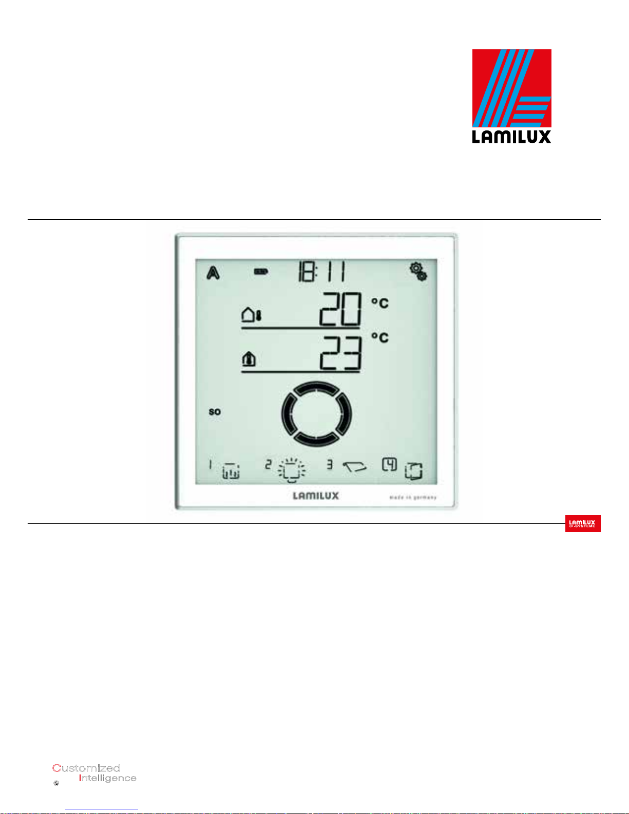
5.3. DISPLAY AND CONTROL OPTIONS ON THE HOME
SCREEN
The display has various areas in which information is displayed and functions can be
accessed.
23 Betrieb des Displays
6. Betrieb des Displays
6.1. Akku laden
Das Display hat einen fest integrierten Akku, der nicht entnommen werden kann. Den Ladestand
der Akkus zeigt das Symbol „Akku“:
Ladezustand sehr gut, Gerät betriebsbereit.
Ladezustand gut, Gerät betriebsbereit.
Ladezustand niedrig, Akku aufladen.
+ Tonsignal alle 15 Minuten. Ladezustand sehr niedrig, Akku aufladen.
Laden Sie das Display vor der Inbetriebnahme auf. Zum Laden verbinden Sie das Display über USB
mit einem Netzsteckdosen-Ladegerät oder einem PC. Das Ladegerät muss einen Ladestrom von
200 mA (oder mehr) liefern.
Abb. 24
Die USB-Ladebuchse befindet sich am unte-
ren Rand des Displays.
FIG. 24
The USB charging
socket is located at
the bottom edge of
the display.
5. OPERATING THE DISPLAY
4.5.3 INSTRUCTIONS FOR INSTALLATION AND GETTING STARTED
Do not open the terminal unit if water (e.g.,
rain) can penetrate: Just a few drops of water
can damage the electronics.
24 Betrieb des Displays
5 Temperatur/Wetter
8 Wippe: Ausgang
wechseln und
manuell bedienen
Ausgänge 9
(Typ, Anzeigeplatz)
4 zu den
Einstellungen
Ladezustand
Akku 2 3* Uhrzeit
Modus 1*
Wochentag 3*
7* Funktionen ausge-
wählter Ausgang
6* Uhrzeit-Empfang
1* Mode
2 Rechargeable battery
charge status
3* Time
4 Go to
settings
5 Temperature/weather
6* Time reception
7* Functions of
selected output
8 Rocker: Switch
output and
operate manually
3* Weekday
9 Selected output
9 Outputs (type,
display slot)
* Only for operation with weather station Loading data

17
Smart Home Control • Revision: 11-05-2016. • As of version 1.7 Subject to technical modifications and errors.
1 – Mode
If a weather station is connected, the current
mode of the selected output is displayed
here.
The mode is changed by tapping on
the area with the symbols (A/Man.).
Pressing and holding in the area with the
symbols (A/Man.) switches all outputs to
automatic at the same time (press and hold
until the high audio signal "long keystroke"
is heard).
A Automatic mode. Automatic functions of
the selected output are active.
Manual mode. Output was operated man-
ually or is switched to manual mode.
After an output has been operated
manually, it remains in manual mode.
Automatic mode is inactive. Define an automatic mode reset, to automatically switch
the output to automatic mode once a day or
a certain time after manual operation (see
section General Settings: Automatic Reset
in the manual and Automatic Reset for the
individual automatic mode descriptions in
the manual).
2 – Rechargeable battery charge status
Observe section 5.1. Charging the rechargeable battery, page 16.
3 – Time, weekday
(only for operation with the weather
station)
The time can be displayed as a 12 or 24hour clock. For more information on setting
the clock, see the section Setting the time in
the manual.
4 – Settings menus
Press briefly to go to the automatic
settings or press for 3 seconds to go to
the basic settings.
The automatic settings are described in the
section Automatic mode in the manual.
The basic settings are described in the sec
-
tion Basic settings in the manual.
5 – Room temperature and weather data
This area displays the internal temperature
value; if you are using the weather station,
also the outdoor/weather data. In this case
you can toggle between the "Temperature"
and "Brightness/Wind" displays by tapping
the area with the values.
25 Betrieb des Displays
Uhrzeit einstellen
im Handbuch.
Kurz drücken, um in die Automatik-Einstellungen zu gelangen oder
3 Sekunden lang drücken, um in die Grundeinstellungen zu gelangen.
Automatik
im Handbuch beschrieben.
Grundeinstellung
im Handbuch beschrieben.
Temperatur-Anzeige:
• Aktuelle Außentemperatur
(nur bei Verwendung der Wetterstation)
• Aktuelle Innentemperatur
Helligkeits-/Wind-Anzeige
(nur bei Verwendung der Wetterstation):
• Aktuelle Helligkeit (Lichtstärke)
• Aktuelle Windgeschwindigkeit
Temperature display:
• Current outdoor temperature
(only when using the weather
station)
• Current indoor temperature
Brightness/Wind indicator
(only when using the weather
station):
• Current brightness
(light intensity)
• Current wind speed

18
Smart Home Control • Revision: 11-05-2016. • As of version 1.7 Subject to technical modifications and errors.
For more information on the values for
brightness and wind, see section 4.3.6 of the
manual. Units for sun and wind, page 181.
6 – Time reception
(only for operation with the weather
station)
If the wireless icon appears on the home
screen, the controller has received the current time through the GPS receiver built into
the weather station within the past 5 minutes.
If no wireless icon appears, then no time signal has been received for more than 5 minutes. The controller's internal clock will keep
working.
7 – Functions of the active output
The functions of the selected output are
shown in the right margin of the display,
for example, the automatic mode status.
You will find a detailed description in section
5.3.1. Meaning of function icons (Automatic
status), page 18.
8 – Rocker for manual operation
9 – Outputs
You can use the rocker to move or switch
the individual outputs manually. The outputs
are shown at the bottom of the screen with
the display slot number and type icon. The
selected output is indicated by a box around
the display slot number.
Note that at this point only those outputs are
displayed for which the displays has been
enabled (see manual section Display slot
in the descriptions of the basic settings for
motorised control units (RF-MSG, weather
station), for relays (RF relay, RF-HE) and for
dimmers (RF-L).
Change the output.
Manually move or switch the selected
output.
Selected output is disabled for manual
operation (alarm function active).
5.3.1 MEANING OF FUNCTION ICONS
(AUTOMATIC STATUS)
If a weather station is used, then the icons
show the automatic mode status of the selected output and the alarm functions applicable for manual mode. A function is only
displayed if it has been activated for the output.
SHADING (BLINDS, AWNINGS, ROLLER SHUTTERS)
Note that several conditions must be met for
an action such as "extend shading". The func
tions are listed here in order of priority. In other
words, the sun protection function is not exe
cuted until all previously stated functions have
released shading.
A detailed description of the automatic
mode functions can be found in the Automatic shading section of the manual.

19
Smart Home Control • Revision: 11-05-2016. • As of version 1.7 Subject to technical modifications and errors.
Alarm functions:
Alarm functions have the highest priority and
prevent manual operation of the output.
Wind alarm. Shading retracted. In Au-
tomatic mode: manual operation may
be released again, even if automatic
functions are still inhibited by a wind
alarm.
Frost alarm (combination of precipi-
tation and low outdoor temperature).
Shading retracted.
Rain alarm. Shading retracted.
Timer and night functions:
Timed closing or timed opening
active.
Value below threshold for dusk/night.
Night closing is performed.
Indoor and outdoor temperature:
Indoor temperature OK. Shading is re
leased.
If the icon is not displayed, the indoor
temperature lock is active.
Outdoor temperature OK. Shading is
released.
If the icon is not displayed, the outdoor
temperature lock is active.
Retraction delay running. Shading
has been locked due to low indoor
temperature.
Sun direction:
Sun in shade area (compass direction).
Shading is released.
Solar protection function:
Brightness threshold for shading ex-
ceeded; extend delay running. Shading is extended after the delay time, if
all other conditions are OK.
Brightness threshold for shading ex-
ceeded. Shading is performed if all
other conditions are OK.
Value dropped below brightness
threshold for shading; retract delay
running. Shading retracts after the
delay time.
Value dropped below brightness
threshold for shading. Automatic solar protection inactive.
WINDOW
Note that several conditions must be met for
an action such as "ventilate on indoor temper
ature". The functions are listed here in order
of priority. In other words, temperature-driven
ventilation is not executed until all previously
stated functions have released ventilation.

20
Smart Home Control • Revision: 11-05-2016. • As of version 1.7 Subject to technical modifications and errors.
A detailed description of the automatic mode
functions can be found in the Automatic window ventilation section of the manual.
Alarm functions:
Alarm functions have the highest priority and
prevent manual operation of the output.
Wind alarm. Windows closed.
Manual mode: Manual operation locked. Automatic mode:
Output can be operated if
the automatic wind lock is active.
Frost alarm (combination of precipi-
tation and low outdoor temperature).
Windows closed.
Rain alarm. Window closed or open
in rain position depending on the setting.
Timer functions:
Timed closing or timed opening active.
Outside temperature:
Outdoor temperature OK. Ventila-
tion is released. If the icon is not displayed, the outdoor temperature lock
is active.
Ventilation function:
Indoor temperature for ventilation ex-
ceeded. Ventilation is performed if all
other conditions are OK.
LIGHT
A detailed description of the automatic
mode functions can be found in the Automatic lighting section of the manual.
Value dropped below dusk threshold.
Light is switched on after a delay of 1
minute. If a lighting period is addition
-
ally defined, switching only occurs
within that period.
Lighting period active. If dusk switch-
ing is additionally defined, switching
only occurs at dusk.
HEATING
A detailed description of the automatic
mode functions can be found in the Heating
section of the manual.
Day mode. The preset day tempera-
ture setpoint is effective.
Night mode (night time). The preset
night temperature setpoint is effective.
The value dropped below the currently
valid temperature setpoint. Heating is on.

GUTTER HEATING
A detailed description of the automatic mode
functions can be found in the Automatic gutter heating section of the manual.
Outdoor temperature is within the
preset range. Heating is on.
5.4. AUDIO SIGNALS
If a button or a touch-sensitive area is actuated, a short audio signal can be heard. If a
key is held down, then you can hear a higher
audio signal to confirm that a long keystroke
was detected. This applies, for example, for
the Settings button to access the basic settings or the SET button for saving. Shortly
before the display battery is discharged, you
will hear a warning signal every 15 minutes
(combination of low and high signal).
5.5. AUDIO SIGNALS
If a button or a touch-sensitive area is actuated, a short audio signal can be heard.
If ER Error is displayed instead of a
sensor value, then the connection to
a connected weather station is interrupted, or the sensor is defective.
Check whether the weather station still has
a voltage supply (fuse). If the problem persists call in a qualified electrician to check
the device.
Installation, checking, commission-
ing and troubleshooting of the device must be carried out by a qualified electrician only (VDE 0100 or
similar).
21
Smart Home Control • Revision: 11-05-2016. • As of version 1.7 Subject to technical modifications and errors.
5.6. TABLE:
MEMORY CAPACITY OF OUTPUTS AND INPUTS
You can use the table to enter the taught devices and functions for the individual
storage slots, and make notes on the automatic mode settings.
Storage slot. Type Display slot Room Keyword

22
Smart Home Control • Revision: 11-05-2016. • As of version 1.7 Subject to technical modifications and errors.
Storage slot. Type Display slot Room Keyword

23
Smart Home Control • Revision: 11-05-2016. • As of version 1.7 Subject to technical modifications and errors.
6. GETTING STARTED
Installation, checking, commission-
ing and troubleshooting of the device must be carried out by a qualified electrician only (VDE 0100 or
similar).
The display is ready for use immediately after
unpacking. You can begin with the basic settings after installing the terminal unit and the
wireless modules if applicable.
The display will already show the room temperature.
Proceed as follows with the installation of the
controller:
1. Installation
2. Basic settings (incl. teaching the wire-
less nodes), see the General Settings
manual.
3. Setting automatic mode, see the Auto-
matic Mode manual. – Only for operation with weather station
6.1. SHORT SETUP
TEACHING THE CONTROL BOX
1.
On the home screen, tap and hold
down the Settings icon (high audio
signal) to access the basic settings.
2.
Go to the LER (Teach) section.
3. Select the LER section.
4.
Briefly press the weather station
icon. Ready for teach-in is indicated
by the animated antenna symbol.
5.
Switch on the power supply to the terminal
unit (16 A circuit breaker in switch cabinet/
fuse box, or press the PRG key inside the
housing.
22 Inbetriebnahme
Innentemperatur (Sen-
sor im Display)
zu den
Einstellungen
Go to
Settings
Indoor temperature
(Sensor in display)
45 Funkverbindungen herstellen
1
2
Grundeinstellung (Sprache) Grundeinstellung (Lernen)
1
2
Home screen
Basic settings
(language)
Basic settings
(teach-in)
45 Funkverbindungen herstellen
1. Auf dem Startbildschirm das Einstellungs-Symbol lange drücken
(hohes Tonsignal), um in die Grundeinstellungen zu gelangen.
2. Zum Bereich LER Lernen wechseln.
1
2
Grundeinstellung (Sprache) Grundeinstellung (Lernen)
3
4
3
4
Basic settings
(teach-in)
Learning

PARAMETRISING THE OUTPUT
1.
On the home screen, tap and hold
down the Settings icon (high audio
signal) to access the basic settings.
2.
Go to the AUSG (outputs) section.
3. Select the AUSG section.
4.
Go to the desired storage slot (output).
Actuate the output with the up/down
buttons to discover which motor or con
sumer is assigned to the storage slot.
Note the function in the table 5.6.: Stor
age slots for outputs and inputs, page
19/20/21.
OUTPUT ASSIGNMENTS
(SEE CONTROL BOX LABELS):
SP01 = Motor 1 230V
SP02 = Motor 2 230V
SP03 = Motor 24V
SP04 = Dimmer
DETERMINING THE TYPE:
5. Select the setting for the output/
storage slot.
6.
Select the setting tYP Type.
Select
mAR (awning), FEN (window), rOL
(shutter)
,
JALO (blind)
or
rES Reserve
(val-
ue flashes).
DETERMINING THE DIRECTION OF ROTATION
Setting the direction of rotation defines the
safe position of a drive. The correct setting
is important for safe operation of automatic
mode, e.g., for wind and rain alarms. The direction of rotation must be set independently of the subsequent setting of the manual
move direction.
Home screen
Basic settings
(language)
Basic setting
(outputs)
51 Ausgänge einrichten
3.6. Ausgänge einrichten
GRUNDEINSTELLUNG > AUSG
Jeder an der Anschluss-Einheit angeschlossene Antrieb oder Verbraucher und jeder im System
eingelernte Funk-Aktor muss in dieser Einstellung eingerichtet werden. Abhängig vom Anschluss
(Jalousie, Markise ...) oder vom Aktor (Motorsteuergerät, Relais ...) werden unterschiedliche Einstel-
lungsmöglichkeiten angezeigt.
Position Bereich Gerätetyp Geräte-
Anzahl
01-02 Anschluss-Einheit Motor 230 V 2
03 Anschluss-Einheit Motor 24 V 1
04 Anschluss-Einheit Dimmer 1
05 bis 08 Displays Display 4
09 WLAN WLAN-Modul 1
10 bis 19 Ausgänge Aktoren 10
20 bis 51 Eingänge Bediengeräte und Sensoren 32
1
2
Grundeinstellung (Sprache) Grundeinstellung (Ausgänge)
3
1
2
3
Outputs
(Storage slot 01)
Outputs
(Storage slot 07)
Outputs
(Storage slot 08)
52 Ausgänge einrichten
4 4 4
Ausgänge (Speicherplatz 07) Ausgänge (Speicherplatz 08)
4
4
4
Back to
Home screen
Setting: Type
Value
Save (long)
Change value
(Up/Down)
Back without saving
Type and
display slot
home screen
54 Ausgänge einrichten
6
Speicherplatz 07 (Typ)
Einstellung: Typ
Speichern (lang)
Wert
Wert ändern (Auf/Ab)
zurück zum
Startbildschirm
24
Smart Home Control • Revision: 11-05-2016. • As of version 1.7 Subject to technical modifications and errors.

5.
Select the setting for the output/
storage slot.
6.
Go to the drEH direction of rota-
tion setting.
7.
Select the drEH setting.
SHADING (AWNING, BLIND, SHUTTER):
Type "awning, blind or shutter"
Check the status of the drive when
the UP button is pressed. You can
move the drive using the up/down
keys to do so.
Select EINF retraction if the shading retracts
on pressing the UP button.
Select AUSF extend if the shading extends on pressing the UP button.
The value flashes and is changed in this
menu by pressing the right/left buttons as
an exception.
WINDOW
Type "Window"
Check the status of the drive when
the UP button is pressed. You can
move the drive using the up/down
keys to do so.
Select SCHL close if the window
closes on pressing the UP button.
Select OEFF open if the window
opens on pressing the UP button.
The value flashes and is changed in this
menu by pressing the right/left buttons as
an exception.
DETERMINING THE MANUAL MOVE DIRECTION:
For drives you can set which button extends
and which retracts, or which opens and
which closes. This adapts the rocker button
assignments to the actual move direction of
the drive and thus facilitates operation for the
user.
25
Smart Home Control • Revision: 11-05-2016. • As of version 1.7 Subject to technical modifications and errors.
Back to
Home screen
Setting: Direction of rotation
Value
Change value (right/
left)
Back without
saving
Type and
display slot
home screen
55 Ausgänge einrichten
6
7
Speicherplatz 07 (Typ) Speicherpl. 07 (Drehrichtung)
Einstellung:
Drehrichtung
Speichern (lang)
Wert
Wert ändern (re/li)
zurück zum
Startbildschirm
Save (long)
Check status
(up/down)
Back to
Home screen
Setting: Direction of rotation
Value
Change value
(right/left)
Back without
saving
Type and
display slot
home screen
56 Ausgänge einrichten
Einstellung:
Drehrichtung
Speichern (lang)
Wert
Wert ändern (re/li)
zurück zum
Startbildschirm
Save (long)
Check status
(up/down)

26
Smart Home Control • Revision: 11-05-2016. • As of version 1.7 Subject to technical modifications and errors.
5.
Select the setting for the output/
storage slot.
6.
Go to the setting mAN Manual
Direction.
7.
Select the mAN setting.
SHADING (AWNING, BLIND, SHUTTER):
Type "awning, blind or shutter"
You can move the drive with the up/down
keys for test purposes.
WINDOW
Type "Window"
You can move the drive with the up/down
keys for test purposes.
DETERMINING THE OPENING/EXTENSION TIME
SHADING (AWNING, BLIND, SHUTTER):
You need to enter the run time for extending/opening and retracting/closing to allow
a move position to be precisely approached.
For this reason, you need to stop the run
time during start-up and set the time now.
5.
Select the setting for the output/
storage slot.
6.
Go to the AUSF extend time setting.
7.
Select the AUSF setting.
Adapt the value (number flashes). Default 235
seconds, setting range from 0 to 300 seconds.
WINDOW
5.
Select the setting for the output/
storage slot.
6.
Go to the OEFF opening time
setting.
7.
Select the OEFF setting.
Back to
Home screen
Setting:
Manual direction
Value
Change value (right/left)
Back without
saving
Type and
display slot
home screen
58 Ausgänge einrichten
Einstellung: Manuell-
Richtung
Speichern (lang)
Wert
Wert ändern (re/li)
zurück zum
Startbildschirm
Save (long)
Check status
(up/down)
Back to
Home screen
Setting:
Extend time
Value
Change value
(Up/Down)
Back without saving
Type and
display slot
home screen
60 Ausgänge einrichten
Einstellung: Ausfahrzeit
Speichern (lang)
Wert ändern (Auf/Ab)
Wert
zurück zum
Startbildschirm
Save (long)
Back to
Home screen
Setting:
Manual direction
Value
Change value (right/left)
Back without
saving
Type and
display slot
home screen
57 Ausgänge einrichten
Einstellung: Manuell-
Richtung
Speichern (lang)
Wert
Wert ändern (re/li)
zurück zum
Startbildschirm
Save (long)
Check status
(up/down)

The outputs can be operated manually to
determine the run times. To do this, proceed
as per the first 4 steps of "parametrising the
output" and measure the times. You can also
refer to the operating instructions for the deployed components (ventilation drive, shading) to determine the run times.
DETERMINING THE CLOSING/RETRACTION TIME
5.
Select the setting for the output/
storage slot.
6.
Go to the EINF retraction time
setting.
7.
Select the EINF setting.
Adjust the value, see opening/extension
time, increase value by 2 sec.!
Parameterisation must be carried out for
each output used. Set unused outputs to reserve in the "Determining the type" step.
DETERMINING THE DISPLAY SLOT
A display slot on the home screen can be as
-
signed to each output (storage slot). In the low-
er part of the display, outputs are then shown
in this order, and can be selected for manual
operation.
While adjusting the outputs, the display slot is
shown on the home screen bottom left near
the type symbol.
5.
Select the setting for the output/
storage slot.
6.
Go to the dISP Display
display slot setting.
7.
Select the
dISP
setting.
Select the display slot (number flashes) or select OFF if you do not want to display the output on the home screen.
The preset automatic functions are sufficient
in most cases. If special adjustments are desired, you can configure them with the help
of the manual, which you can download at
www.lamilux.com/downloads.
27
Smart Home Control • Revision: 11-05-2016. • As of version 1.7 Subject to technical modifications and errors.
Back to
Home screen
Setting:
Opening run time
Value
Change value
(Up/Down)
Back without saving
Type and
display slot
home screen
61 Ausgänge einrichten
Einstellung: Öffnungs-
fahrzeit
Speichern (lang)
Wert ändern (Auf/Ab)
Wert
zurück zum
Startbildschirm
Save (long)
Back to
Home screen
Setting: Display
Display slot
Value
Change value
(Up/Down)
Back without saving
Type and
display slot
home screen
66 Ausgänge einrichten
Einstellung: Display-An-
zeigeplatz
Speichern (lang)
Wert ändern (Auf/Ab)
Wert
zurück zum
Startbildschirm
Save (long)

28
Smart Home Control • Revision: 11-05-2016. • As of version 1.7 Subject to technical modifications and errors.
7. OPERATION OF THE WEATHER STATION
8. WLAN MODULE
7.1. MAINTENANCE OF THE WEATHER STATION
WARNING!
Risk of injury due to automatically
moving components!
Automatic control means that sys
tem components can start to move
thus exposing persons to danger.
• Always disconnect the device from the
power supply for maintenance and
cleaning.
The device should be regularly checked for
soiling twice a year and cleaned if necessary.
Heavy soiling can impair the sensor function.
ATTENTION!
The device may be damaged if water
enters the housing.
• Do not clean with pressure cleaners or
steam jets.
8.1. DESCRIPTION
The WiFi module connects the smart home
control with the Lamilux Smart Home App.
Devices and drives can be operated manually
with the app installed on your mobile device.
Measured values from sensors inside the
system and the weather station can also be
viewed.
The WiFi module receives data from the app
via the in-house WiFi or mobile internet (VPN).
These data are then forwarded by the inter
face to the Smart Home Control via the wireless link. Similarly, data from the Smart Home
Control are transferred to the app.
8.1.1 SCOPE OF SUPPLY
• Interface in housing for CEE 7/4 socket.
STOP

29
Smart Home Control • Revision: 11-05-2016. • As of version 1.7 Subject to technical modifications and errors.
8.1.2 TECHNICAL DATA
The product complies with the provisions of
EU directives.
8.2. NOTES ON GETTING STARTED
8.2.1 NOTES ON INSTALLATION
Installation, checking, commission-
ing and troubleshooting parts of
the electrical installation must be
carried out by a qualified electrician
only (VDE 0100 or similar).
The device is designed for the intended use
only. Any unauthorised modification or failure to observe the instructions will void warranty or guarantee claims.
After unpacking, check the device immediately for any mechanical damage. If transport
damage is present, immediately inform the
supplier.
The device may only be operated as a stationary system, that is, only in mounted condition, following completion of all installation
and commissioning work, and only in the
intended environment.
Lamilux is not liable for changes in standards
after publication of the operating manual.
8.2.2 REQUIREMENTS
To be able to use the WiFi module, the
following criteria must be fulfilled:
• You must have a mobile device (smart-
phone or tablet) with the Android operating system 4.0.3., Apple iOS 8.0 or
higher.
• A Smart Home Control must be set up.
• A router and a configured wireless net-
work (WLAN) must be available. Secure your WLAN against unauthorised
access by taking appropriate security
measures such as encryption, etc.!
8.2.3 NOTES ON WIRELESS EQUIPMENT
When planning systems with devices that
use wireless communication methods, attention must be paid to sufficient wireless reception. The range of wireless controls is restricted by legal regulations for radio equipment
as well as by conditions in the building.
Avoid sources of interference and obstacles
between the transmitter and receiver result-
Dimensions
interface
approx. 67 x 110 x 91
(W x H x D, mm)
Weight
interface
Approx. 260 g
Housing
material
Plastic, black
Degree of protection
IP20
Ambient
temperature
Operation -20...+50 °C,
Storage -55...+70°C
Ambient
humidity
max. 95% rF,
Avoid condensation
Operating
voltage
230 V AC (safety
plug CEE 7/4)
Radio frequency 868.2 MHz and 2.4 GHz

30
Smart Home Control • Revision: 11-05-2016. • As of version 1.7 Subject to technical modifications and errors.
ing in the disruption of wireless communication. These include, for example:
• Walls and ceilings (especially concrete
and sun protection glazing).
• Metallic surfaces in the vicinity of the
mobile nodes (e.g., aluminium construction of a conservatory).
• Other wireless devices and powerful
local transmitter systems (e.g., wireless
headphones) which transmit on the
same frequency (868.2 MHz). Keep a
minimum distance of 30 cm between
radio transmitters.
8.2.4 INSTRUCTIONS FOR INSTALLATION AND GETTING
STARTED
Never expose the device to water (rain). This
could damage the electronics. A relative humidity of 95% must not be exceeded. Avoid
condensation.
8.3. SETTING UP MODULES, WIFI, APP
The WiFi module connects to your in-house
WLAN on one side and additionally establishes a wireless connection to the Smart
Home Control.
8.3.1 INSTALLING THE APP
FOR ANDROID DEVICES:
Open the Google Play Store and install the
Lamilux Smart Home app.
FOR IPAD/IPHONE:
Open the AppStore and install the Lamilux
Smart Home app.
8.3.2 STARTING UP THE WIFI MODULE
The module is plugged into a power socket
(CEE 7/4). The supply voltage must be 230
VAC / 50 Hz.
You can determine the current device status
via the status LED display at the side:
4 Einrichtung von Modul, WLAN, App
2
1
1
2
FIG. 25
1 LED
2 Reset button (recessed)
LED off Initialisation
Initialisation can take
up to 1 minute.
LED on
WiFi configuration mode
To use the WiFi module, you first
need to configure your own wireless
settings (section WiFi configuration)
FIG. 26
WiFi settings screenshot
4 Einrichtung von Modul, WLAN, App
Die Initialisierung kann bis zu 1 Minute dauern.
Um das WLAN-Modul verwenden zu können, müssen Sie
zuerst Ihre hauseigenen WLAN-Einstellungen konfigurieren
(-> Abschnitt WLAN konfigurieren)
Abb. 2 Screenshot WLAN-Einstellungen
2
1

31
Smart Home Control • Revision: 11-05-2016. • As of version 1.7 Subject to technical modifications and errors.
8.3.3 CONFIGURING WIFI
Requirements: The status LED of the WiFi
module glows permanently.
List the available wireless networks on
your mobile device. Select the network
"WLAN-Schnittstelle SOL" (WiFi interface
SOL). The mobile device then associates
with the WiFi module.
Launch the app. Fields where your can enter
your in-house wireless network settings "Network Name (SSID)", "Encryption" and "Key"
are displayed.
Now press "Save" in the top right in the menu
view. After about 10 seconds, the LED on
the WiFi module flashes regularly for a short
time. The module is now connected to your
WiFi router.
First, again list the available wireless networks and connect to your own wireless network. Then restart the app.
8.3.4 CONNECTING TO THE SMART HOME CONTROL
After successfully completing the WiFi configuration and restarting the Lamilux Smart
Home App, a message appears, stating that
a Smart Home Control needs to be taught.
To do so, briefly interrupt the power supply
to the Smart Home Control (switch the circuit
breaker on the terminal unit off and back on
again).
A short audio signal indicates that the Smart
Home Control has been successfully taught.
The interface is now connected to the Smart
Home Control and can transmit data to the
Lamilux Smart Home App.
LED flashes regularly
at short
intervals
Connected to router
The WiFi module is now connected
to your router. Connect your mobile
device to the same wireless network
and launch the app.
LED goes
out briefly
every 2
seconds
No WiFi connection to router.
Connection could not be established to your router. You may need
to move the WiFi module closer to
the router.
If you changed your router's access
data, reset the module to the factory
defaults (Section Resetting the WiFi
module to the factory defaults) and
proceed to configure as per section
WiFi.
FIG. 27
Screenshot no WiFi module
5 Einrichtung von Modul, WLAN, App

32
Smart Home Control • Revision: 11-05-2016. • As of version 1.7 Subject to technical modifications and errors.
The app is now ready for use.
Alternatively, the Smart Home Control can
be taught by pressing the PRG button inside
the housing.
However, this may only be done by a qualified
electrician, as the PRG button is inside the ter
-
minal unit.
WARNING!
Electrical voltage!
The programming button of the
terminal unit is located inside the
housing and thus in the vicinity of
unprotected live components.
• The device may only be taught in this
way by a qualified electrician (as per
VDE 0100).
8.3.5 RESETTING THE WIFI MODULE TO THE
FACTORY SETTINGS
The factory settings can be restored by
pressing the reset button. The initialisation
must be complete for this; identifiable by
the LED status (LED is glowing or flashing).
Hold down the recessed reset button on
the side of the device next to the LED with
a pointed object for 5 seconds.
8.4. USING THE APP
The app has two sections: Overview and Operations.
8.4.1 OVERVIEW
FIG. 28
Screenshot Overview page
This shows you a list of all the occupied slots
on the Smart Home Control. The correspond
ing slot is selected by tapping and the view
changes to the Operations page. You can
additionally change the display name in the
app.
CHANGING THE NAME IN IOS:
• Click "Edit" in the top left.
• Tap on the red circle with a minus sign
to the left of the item.
• Alternatively: Swipe the item to the left
with your finger.
• This opens the "Edit" menu to the
right of the item. Tap "Edit" and enter
the new name.
6 Bedienung der App
Alternativ kann die Smart Home Steuerung durch drücken der PRG-Taste im Gehäuseinnern ein-
gelernt werden. Dies darf jedoch nur von einer Elektrofachkraft durchgeführt werden, da sich die
PRG-Taste im Innern der Anschluss-Einheit befindet.
WARNUNG!
Elektrische Spannung!
Die Programmier-Taste der Anschluss-Einheit befindet sich im Innern des
Gehäuses und somit in der Nähe ungeschützter spannungsführender
Bauteile.
• Das Gerät darf auf diese Weise nur von einer Elektrofachkraft
(lt. VDE 0100) eingelernt werden.
3.5. WLAN-Modul auf Werkseinstellung zurücksetzen
Die Werkseinstellungen lassen sich über die Reset-Taste wieder herstellen. Dazu muss die Initiali-
sierung abgeschlossen sein, erkennbar am LED-Status (LED leuchtet oder blinkt).
Halten Sie die versenkte Reset-Taste an der Seite des Geräts neben der LED mit einem spitzen Ge-
genstand für 5 Sekunden gedrückt.
4. Bedienung der App
Die App hat zwei Bereiche: Übersicht und Bedienungsseite.
4.1. Übersicht
Abb. 4 Screenshot Übersichtsseite

33
Smart Home Control • Revision: 11-05-2016. • As of version 1.7 Subject to technical modifications and errors.
Either confirm by pressing "OK" or close
the input window by pressing "Cancel".
CHANGING THE NAME IN ANDROID:
• Press and hold the desired item until a
text box with keyboard appears.
• Confirm by pressing "OK" or tap the
screen outside the keyboard section to
cancel.
8.4.2 CONTROL AND DISPLAY PAGE OF THE APP
Switch to the next/previous position by swiping
to the right or left with your finger in the upper
half of the view.
On the left in the top menu bar you can find
the “<Overview” button to get back to the
overview page.
FIG. 29
Drive example
FIG. 30
Sensor example
8.4.2.1 OPERATIONS AND DISPLAY PAGE IN THE APP
The top half of the display shows the functions of the selected drive or device, or the
data of the indoor sensor.
1 Text display:
• Name
• For shading and windows: current
move position
• For heating and lights: current status (if
applicable dimming brightness)
• For sensors: current values
2 Button manual/automatic:
• Tap the button to switch between manual mode and automatic mode
7 Bedienung der App
vergeben den neuen Namen. Bestätigen Sie entweder mit „OK“ oder schließen sie das
Eingabefenster mit „Abbrechen“.
erscheint.
um abzubrechen.
Abb.5
Beispiel Antrieb
Abb. 6
Beispiel Sensor
4
1
2
3
4
1
1
2
3
4
Abb. 6
Beispiel Sensor
4
1
1
4

34
Smart Home Control • Revision: 11-05-2016. • As of version 1.7 Subject to technical modifications and errors.
3 Rocker:
• Tapping the rocker lets you trigger
short move commands or switching
commands
• If you want a drive to move permanently
up/down, hold down the rocker switch
for at least one second
4 Weather data
• Rain (yes/no)
• Brightness
• Wind force
• Outdoor temperature
9. WIRING DIAGRAM
Smart Home Steuerung • Stand: 11.05.2016 • Technische Änderungen und Irrtümer vorbehalten.
nicht
Antrieb
Antrieb
LED-Strip
Netz
belegt
Powerbox
230 V AC
230 V AC
230 V AC, 50 Hz
Not assigned
Weather station
Drive
24 V DC
Drive
230 V AC
Drive
230 V AC
LED strip
Powerbox
Mains supply
230 V AC, 50 Hz
M M M M
M M M M
Cable 4 x 0.75 mm²
Group 2
Motor 2 230 V
Shading max. 3 units
Ventilation drive max. 4 units
Group 1
Motor 1 230 V
Ventilation drive max. 4 units
Group 3
24 V
Shading max. 2 units
Cable 4 x 0.75 mm²
Must be provided
by customer.
Possibility to connect multiple drives to one control
box and/or in case of cable
extensions to the drives
The box must be installed
within 3 m of the glass
element as standard.
M M
Cable 2 x 0.75 mm²
Cable 2 x 0.75 mm²
Weather station

35
Smart Home Control • Revision: 11-05-2016. • As of version 1.7 Subject to technical modifications and errors.
10. CONNECTOR
VOLTAGE SUPPLY/SUPPLY CABLE MOTOR 230 V
L PE N
N PE L1 L2
VOLTAGE SUPPLY/SUPPLY CABLE MOTOR 24 V
Connection is polarity-independent!
WIRE 2 WIRE 1

SMART HOME EN_08/2016
The technical data printed in this brochure was accurate when this brochure went to press and is subject to change without notice. Our technical specifications are based
on calculations and supplier specifications, or have been determined by independent testing authorities within the scope of applicable standards.
Thermal transmission coefficients for our composite glazing were calculated using the finite element method with reference values in accordance with DIN EN 673 for
insulated glass. Based on empirical values and specific characteristics of the plastics, a temperature vector of 15 K was defined as the vector between the outer surfaces
of the material. Functional values refer to test specimens and the dimensions used in testing only. We cannot provide any further guarantees of technical values. This
particularly applies to changes in installation locations, or if dimensions are re-measured on site.
LAMILUX Heinrich Strunz GmbH
Zehstraße 2 . PO Box 1540 . 95111 Rehau, Germany . Tel.: +49 (0) 92 83 / 5 95-0 . Fax +49 (0) 92 83 / 5 95-29 0
E-Mail: information@lamilux.de . www.lamilux.com
Scan this to discover more
about LAMILUX daylight systems!
ROOFLIGHT DOME F100 GLASS ELEMENT F
CONTINUOUS
ROOFLIGHT B
RENOVATION
SMOKE AND HEAT EXHAUST
VENTILATION SYSTEMS
BUILDING CONTROL SYSTEMS
FIBRE-REINFORCED
COMPOSITES
CONTINUOUS
ROOFLIGHT S
GLASS ARCHITECTURE PR60
SMOKE LIFT TWIN
ROOFLIGHT DOME F100 ROUND
GLASS ELEMENT F100 ROUND
CONTINUOUS
ROOFLIGHT W|R
 Loading...