

CALDAIE MURALI E TERRA A GAS
GRUPPI TERMICI IN GHISA E IN ACCIAIO
GENERATORI DI ARIA CALDA
TRATTAMENTO ACQUA
CONDIZIONAMENTO
BRUCIATORI
AZIENDA CERTIFICATA ISO 9001
0444 351044
Le illustrazioni e i dati riportati sono indicativi e non impegnano. La LAMBORGHINI si riserva il diritto di apportare senza
Las ilustraciones y los datos son indicativos y no comprometen. LAMBORGHINI se reserva el derecho de realizar sin preaviso
The illustrations and data given are indicative and are not binding on the manufacturer. LAMBORGHINI reserves the right to
make those changes, considered necessary, for the improvement of the product without forwaming the customer.
Les illustrations et les données sont à titre indicatif et sans engagement. La LAMBORGHINI se réserve le droit d'apporter sans
Die LAMBORGHINI behält sich das Recht vor, ohne Voranküdigung die adequatesten Verbesserungen bezüglich der Entwicklung
obbligo di preavviso tutte le modifiche che ritiene più opportuno per l'evoluzione del prodotto.
todas las modificaciones que estime oportuno para la evolución del producto
obligation de prèavis les modifications qu'elle retient le plus nécessaires pour l'evolution du produit.
Die Abbildungen und die angegebenen Daten sind, als indikativ und nicht verpflichtend zu verstehen.
des Produktes vorzunehmen.
LAMBORGHINI CALOR S.p.A.
TEL. ITALIA 0532/359811 - EXPORT 0532/359913
FAX ITALIA 0532/359952 - EXPORT 0532/359947
VIA STATALE, 342
44040 DOSSO (FERRARA)
Cod. 97.50625.0
ITALIA
11/2003
-VI
MANUALE DI
INSTALLAZIONE E
MANUTENZIONE
MONTAGE
UTILISATION
ENTRETIEN
CALDAIE IN GHISA AD ALTO RENDIMENTO
CHAUDIERE EN FONTE A HAUT RENDEMENT
CALDERAS DE HIERRO FUNDIDO DE ALTO RENDIMENTO
CAST IRON BOILER FOR HIGH EFFICIENCY
SPEZIALHEIZKESSEL AUS GUSSEISEN
MANUAL DE
INSTALACION Y
MANTENIMIENTO
INSTALLATION AND
MAINTENANCE
MANUAL
HANDBUCH
FÜR INSTALLATION
UND WARTUNG
30

2 79

78
3
ITALIANO
FRANCAIS
ESPANOL
4
Leggere attentamente le istruzioni ed avvertenze contenute sul presente libretto in quanto
forniscono importanti indicazioni riguardanti la sicurezza d'installazione, d'uso e di
manutenzione.
Conservare con cura questo libretto per ogni ulteriore consultazione.
L'installazione deve essere effetuata da personale qualificato che sarà responsabile del
rispetto delle norme di sicurezza vigenti.
18
Lire attentivement le mode d'emploi et les instructions du présent livret car ils fournissent
des indications de l'emploi et de la manutention.
Conserver avec soin ce livret pour ultérieures consultations.
L'installation doit être effectuée par un personnel qualifié qui sera responsable de respecter
les normes de sécurité en viguer.
32
Leer atentamente las instrucciones y las advertencias que contiene el presente folleto ya
que dan indicaciones importantes relativas a la seguridad de la instalación, al uso y al
mantenimiento.
Conservar con cuidado este folleto para cualquier ulterior consulta.
La instalación debe ser efectuada por personal cualificado que tendrá la responsabilidad
de respetar las normas de seguridad vigentes.
Las partes del embalaje ( bolsas de plástico, espuma de poliestirol, etc... ) no hay que
dejarlas al alcance de los niños ya que son potenciales fuentes de peligro.
Leer atentamente y conservar los cupones de garantía.
ENGLISH
DEUTSCH
46
Read carefully all warnings and instructions contained in this manual as they give
important safety instructions regarding installation, use and maintenance. Keep
this manual for future reference. Installation must be carried out by qualified
personnel who will be responsible for respecting existing safety regulations.
60
Bitte lesen Sie die Anleitungen und Hinweise in dem vorliegenden Handbuch aufmerksam durch. Sie enthalten wichtige Informationen bezüglich Installation, Gebrauch und
Wartung. Bewahren Sie dieses Handbuch zum späteren Nachschlagen sorgfältig auf.
Die Installation ist von qualifiziertem Fachpersonal unter Berücksichtigung der geltenden Sicherheitsvorschriften durchzuführen.
INDICE PAGINA
GENERALITÀ 7
DIMENSIONI E CARATTERISTICHE TECNICHE 7
COMPONENTI PRINCIPALI 9
INSTALLAZIONE 10
COLLEGAMENTI ELETTRICI - SCHEMI 10
VERIFICHE E CONTROLLI 12
ACCENSIONE - SPEGNIMENTO 12
MANUTENZIONE PERIODICA 12
ABBINAMENTO CALDAIA - BOLLITORE 13
MONTAGGIO KIT ACOUSTIC COVER 15
MONTAGGIO KIT OROLOGIO PROGRAMMATORE 16
4
77
Complimenti...
… per l’ottima scelta!
La LAMBORGHINI garantisce non solo la qualità del prodotto, ma anche l'efficienza della sua rete di
assistenza tecnica.
PER OGNI NECESSITÀ RIVOLGERSI ALLA PIÙ VICINA AGENZIA LAMBORGHINI.
Leggere attentamente le istruzioni ed avvertenze contenute sul presente libretto in quanto forniscono importanti indicazioni riguardanti la sicurezza d’installazione, d’uso e di manutenzione.
Conservare con cura questo libretto per ogni ulteriore consultazione.
L’installazione deve essere effettuata da personale qualificato che sarà responsabile del rispetto delle norme di sicurezza vigenti.
576
6
75
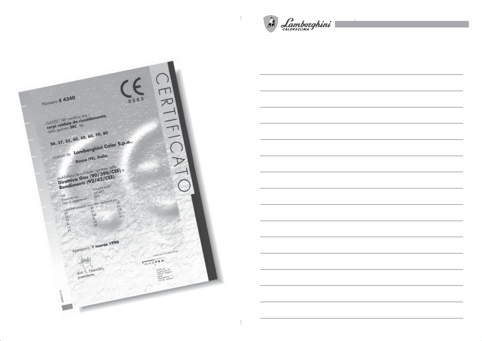
Le caldaie in ghisa ad alto rendimento SEC hanno superato
test di omologazione europei e sono in linea con le più restrittive
norme in fatto di sicurezza e rendimento.
i
74
7
GENERALITÀ
La serie SEC 30 è un generatore di calore ad alto rendimento per il riscaldamento domestico o industriale,
adatto a funzionare con bruciatori di combustibili liquidi e/o gassosi.
Il corpo caldaia è costituito da elementi in ghisa, assemblati con biconi e tiranti in acciaio, il cui profilo è
stato particolarmente curato con un ottimale ripartizione delle alette, che consente un’alta efficacia termica
e conseguente alto risparmio energetico.
L’estetica ed il completo isolamento sono assicurati da un elegante cruscotto, da un mantello verniciato e da
un rivestimento in lana di vetro di grosso spessore che riduce al minimo le dispersioni di calore verso
l’ambiente.
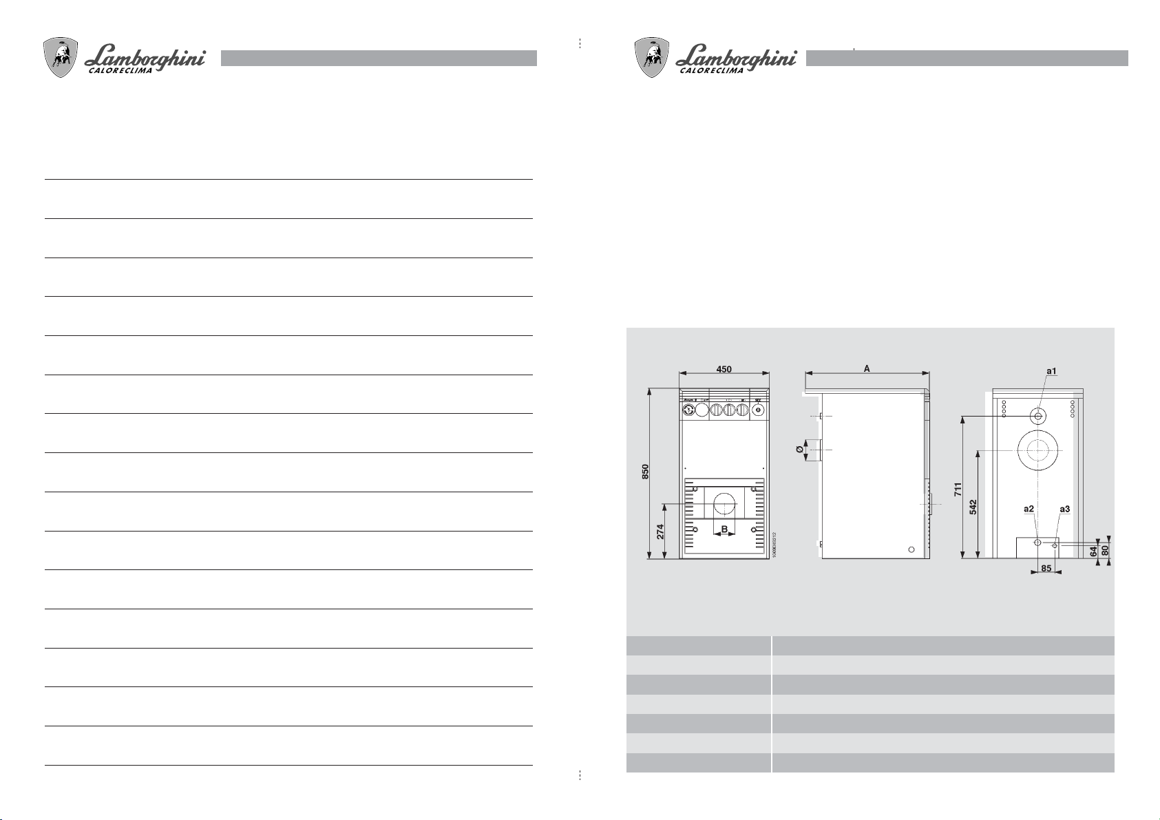
DIMENSIONI
Fig. 1
a1
a2
a3
A
B
Ø
mm
mm
mm
SEC 30
Mandata impianto 1 1/2"
Ritorno impianto 1 1/2"
Scarico caldaia 1/2"
420
105
130
CARATTERISTICHE TECNICHE
PORTATA
TERMICA UTILE
PORTATA
TERMICA NOMINALE
PORTATA UTILE
REGOLABILE FINO A
N° ELEMENTI
CONTENUTO ACQUA
LUNGHEZZA CÁM. COMB.
DIMENSIONI CÁM. COMB.
PRESSIONI D'ESERCIZIO
PERD. CARICO CÁM. COMB.
VOLUME CÁM. DI COMB.
PERDITE DI
CARICO ACQUA
PESO CORPO
kW
kcal/h
kW
kcal/h
kW
kcal/h
lt
mm
mm
bar
∆p mbar
lt
∆t 10
∆t 20
kg
SEC 30
30,6
26300
34,0
29200
24,3
20900
3
14
386
260x310
4
0,10
20,15
1,8
105
8
73
N.B.: - La temperatura massima d'esercizio dell'acqua di riscaldamento dell'impianto è di 90 °C.
- La temperatura minima d'esercizio dell'acqua di riscaldamento dell'impianto è di 45 °C.
72
9
MONTAGE DER PROGRAMM-SCHALTUHR
Den Deckel vom entsprechenden Schaltfeld abnehmen und die Schaltuhr mit den 4 beiliegenden Schrauben (Abb. 17) befestigen. Die Schaltuhr durch Verbindung der Kontakte 1 und 2 an PHASE und NULLEITER, sowie die Kontakte 3 und 5 der Schaltuhr in Serie der Thermostatleitung elektrisch anschließen. (Abb. 18)
Abb. 17
PROGRAMMIERUNG
Durch Drehen der Programmscheibe im Uhrzeigersinn wird die gewählte Stunde eingestellt, wie auf einer
normalen Uhr. Die Einschaltzeiten können durch Senken der beweglichen Tastfüßchen gewählt werden: bis
zu minimal 15-Minuten-Intervalle (jedes bewegliche Tastfüßchen).
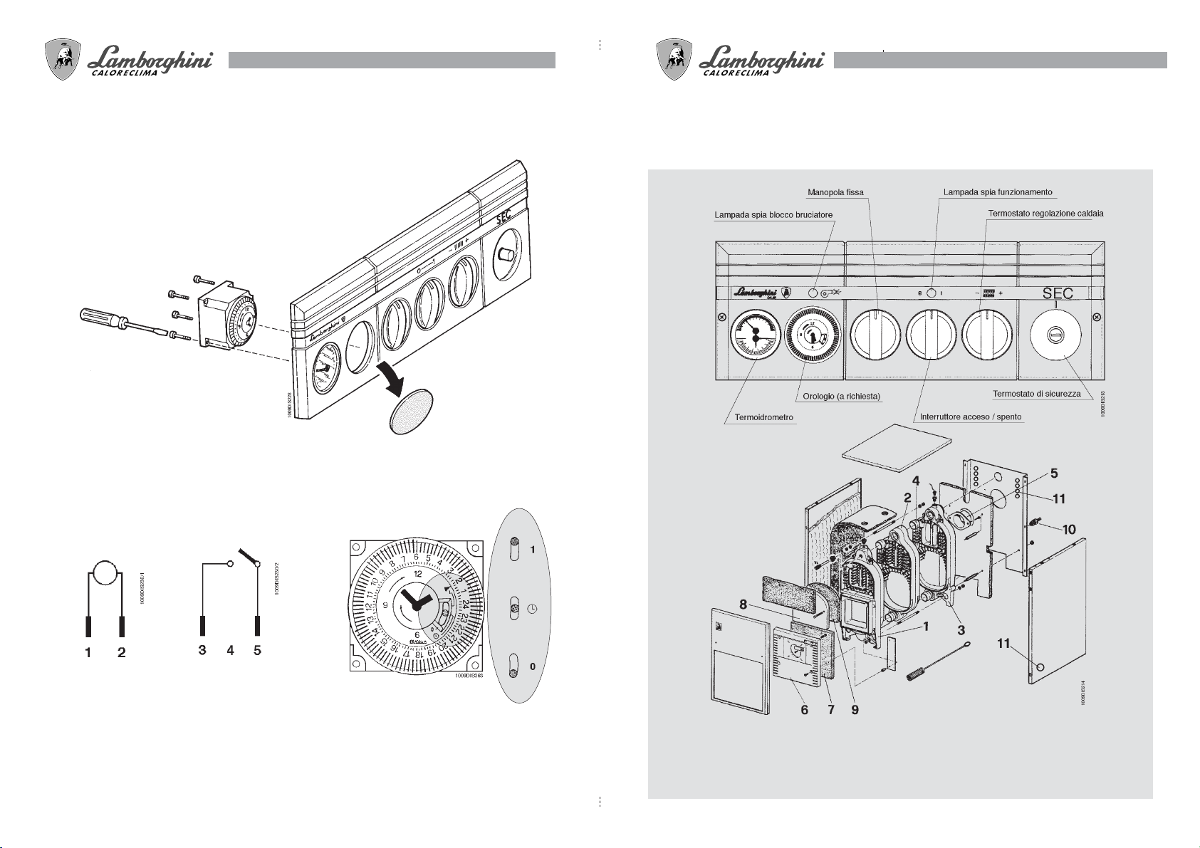
COMPONENTI PRINCIPALI
CRUSCOTTO SEC 30
Fig. 2
Anschlußklemmleisten
230 V - 50/60 Hz
Der Umschalthebel neben den beweglichen Tastfüßchen erlaubt die folgenden drei Einstellmöglichkeiten:
1 Hebel auf Stellung “I” : Heizbetrieb des Kessels für die Anlage ist ausgeschlossen
2 Hebel auf Stellung “O”: Kessel bleibt für die Heizung durchgehend in Betrieb und wird über Kessel-
und Raumthermostat gesteuert.
3 Hebel in Stellung zwischen “I” und “O”: automatischer Kesselbetrieb für die Heizung nach dem vom
Betreiber anhand der beweglichen Zeiger eingestellten Programm.
Hauptschalter
16 A - 250 V ~
Abb. 18
1 Elemento anteriore
2 Elemento intermedio
3 Elemento posteriore
4 Bicono
5 Attacco camino
6 Portina portabruciatore
Fig. 3
7 Isolante portina portabruciatore
8 Portina per pulizia
9 Isolante portina pulizia
10 Rubinetto scarico
11 Fori per pressacavi
10
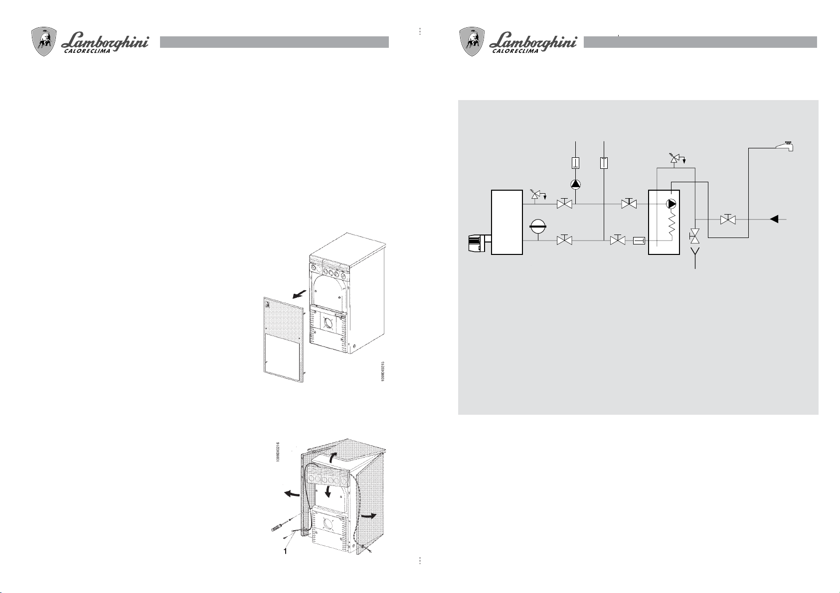
CiR
VR
S
B
CALDAIA
CiB
BOLLITORE
SCARICO
RUBINETTO
DI UTILIZZO
ACQUEDOTTO
1009DIS223
VS
VE
VS
71
INSTALLAZIONE
L’installazione della caldaia deve essere effettuata solo da Personale Qualificato, seguendo le indicazioni
del Costruttore ed in ottemperanza a tutte le leggi e disposizioni che regolano la materia. Si raccomanda in
particolar modo il rispetto delle norme in materia di sicurezza e di quelle che regolano la costruzione e
l’ubicazione delle canne fumarie.
ALLACCIAMENTO IDRAULICO
Eseguire l’allacciamento idraulico dell’apparecchio rispettando le indicazioni poste in prossimità di ogni
attacco e quelle riportate nella figura 1 di questo libretto. L’allacciamento deve essere fatto in modo che i
tubi siano liberi da tensioni ed è d’obbligo montare la valvola di sicurezza sul circuito riscaldamento, in un
punto il più vicino possibile alla caldaia, senza che vi sia, tra questa e la valvola, alcuna ostruzione od
organo d’intercettazione.
L’apparecchio non viene fornito di vaso di espansione; il suo collegamento deve essere pertanto effettuato a cura dell’Installatore. A tal
proposito si ricorda che la pressione dell’impianto, a freddo, deve
essere compresa tra 0,5 e 1,5 bar.
COLLEGAMENTO ALLA CANNA FUMARIA
Si raccomanda di collegare la caldaia ad una buona canna fumaria,
costruita nel rispetto delle normi vigenti. Il condotto tra caldaia e
canna fumaria deve essere di materiale adatto allo scopo, ovvero
resistente alla temperatura ed alla corrosione. Nei punti di giunzione
si raccomanda di curare la tenuta e di isolare termicamente tutto il
condotto tra caldaia e camino al fine di evitare la formazione di
condensa.
Fig. 4
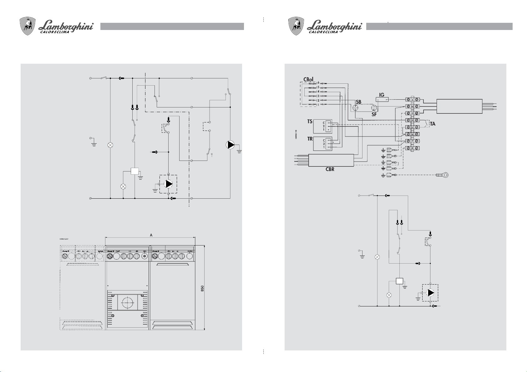
COLLEGAMENTI ELETTRICI - SCHEMI
Effettuare i collegamenti dei circolatori, del bruciatore e dell’eventuale termostato ambiente, rispettando le indicazioni degli schemi
allegati (Figg. 6/7). Si raccomanda di interporre tra la rete e l’apparecchio un interruttore bipolare, con apertura dei contatti di almeno
3 mm, munito di fusibili di 5A max.
Utilizzare per ogni collegamento elettronico i pressacavi (skintop) in
dotazione.
Si raccomanda inoltre di collegare l’apparecchio ad un buon impianto di terra.
La Lamborghini Calor s.p.a. declina ogni responsabilità per danni
a persone o a cose, causati per il mancato collegamento dell’apparecchio ad un buon impianto di terra.
HYDRAULIKKREISLAUF SEC 30 + BVE
KESSEL
LEGENDE
B Brenner
CiB Speicherpumpe
CiR Anlagenumwälzpumpe
S Absperrklappe
VE Ausdehnungsgefäß
VR Rückschlagventil
VS Sicherheitsventil
BOILER
WASSERABFLUß
BENUTZHANN
WASSERLEITUNG
Abb. 12
N.B.: Il cavo bruciatore (Pos. 1 Fig. 5) può essere posizionato, a
seconda della necessità dell’utente, a destra oppure a sinistra.
Fig. 5
70
11
PINZIPSCHEMA SEC 30 + BVE
LEGENDE
B Brenner
CiB Speicherpumpe
CiR Anlagenumwälzpumpe
EI Wahlschalter SOMMER/
WINTER
IG Hauptschalter
SB Störlampe
SF Betriebslampe
TA Raumthermostat
TB Speicherthermostat
TR Regelthermostat
TS Sicherheitstemperatur-
wächter
TP Vorheriger thermostat
IG
SB
1
1
3
4
2
1
TR
C
C
TS
2
5
B
L
3
SF
N
BRAUN
2
TP
C
6
4
TA
5
6
8
7
2
WEIß
BLAU
CiR
ROT
4
C
TB
1
2
3
5
6
CiB
EI
1
2
1009DIS1200
SCHEMA DI COLLEGAMENTO SEC 30
FEMM. 6 POLI
MAS. 6 POLI
Per l'installazione del bollitore,
eliminare il conduttore.
MARRONE
CAVO 4x1 mmq PVC-HT
COLL. APPARECCHIATURA
CONTROLLO BRUCIATORE
NERO
GIALLO/V.
SCHEMA DI PRINCIPIO SEC 30
L
AZZURRO
IG
MARR.
CAVO 3x1 mmq PVC-HT
AZZ.
ALIMENTAZIONE DA
G./V.
RETE 220Vac
Fig. 6
1
Abb. 10
3
4
2
1
TR
C
C
3
SF
TS
2
6
4
TA
5
5
1009DIS1199
A= 900 (Kombination mit BVE 80)
A= 1050 (Kombination mit BVE 120)
Abb. 11
LEGENDA
B Bruciatore
CBr Collegamento bruciatore
CBol Connettore bollitore
IG Interruttore generale
SB Spia di blocco
B
SB
N
6
7
Circolatore di
riscaldamento
2
Fig. 7
8
SF Spia di funzionamento
TA Termostato ambiente (eventuale)
TR Termostato di regolazione
TS Termostato di sicurezza
12
69
VERIFICHE E CONTROLLI
PRIMA DELL'ACCENSIONE INIZIALE
Prima dell’accensione iniziale, è buona norma controllare che:
a l’impianto sia riempito alla giusta pressione e sia ben sfiatato;
b non vi siano perdite d’acqua o di combustibile;
c l’alimentazione elettrica sia corretta;
d tutto il condotto fumi sia stato eseguito correttamente e che non sia troppo vicino o attraversi parti
infiammabili;
e non vi siano sostanze infiammabili nelle vicinanze dell’apparecchio;
f il bruciatore sia proporzionato alla potenza di caldaia;
g le valvole d’intercettazione acqua siano aperte.
DOPO L'ACCENSIONE INIZIALE
Dopo la prima accensione è buona norma controllare che:
● il bruciatore funzioni correttamente.
Questo controllo va fatto con gli appositi strumenti;
● i termostati funzionino correttamente;
● l’acqua circoli nell’impianto;
● l’evacuazione dei fumi avvenga completamente attraverso il camino.
ACCENSIONE - SPEGNIMENTO
ACCENSIONE INIZIALE
Effettuati i controlli preliminari, si può procedere con le seguenti manovre di accensione:
1 aprire la valvola d’intercettazione combustibile (eventuale);
2 regolare il termostato caldaia (Fig. 2) al valore desiderato;
3 chiudere l’interruttore a monte della caldaia e l’interruttore acceso/spento (Fig. 2) posto sul pannello
comandi.
REINIGUNG DES KESSELS
● Das Gerät spannungslos schalten;
● die Verkleidungsbleche 1,2 und 3 (Abb. 8)
abnehmen;
● die Brennkammer reinigen
● den gesamten Abgasweg kontrollieren und
eventuell reinigen.
Zur Reinigung des Brenners beachten Sie bitte die
Betriebsanleitung des Brenners.
Drahtbürste
Schrauben
SPEGNIMENTO
Per brevi periodi di sosta è sufficiente agire sull’interruttore acceso/spento (Fig. 2) posto sul pannello
comandi.
Per lunghe soste durante il periodo invernale, onde evitare danni causati dal gelo, è necessario introdurre
l’apposito antigelo nell’impianto o svuotare quest’ultimo completamente.
MANUTENZIONE PERIODICA
La manutenzione della caldaia deve essere eseguita da Personale Qualificato.
E’ buona norma far eseguire il controllo dell’apparecchio almeno una volta all’anno, prima della stagione
invernale. Tale controllo deve riguardare, oltre lo stato di pulizia della caldaia, anche il funzionamento
corretto di tutti i suoi dispositivi di controllo e di sicurezza nonché il bruciatore.
Deve essere inoltre controllato lo stato di tutto lo scarico fumi.
Drahtbürste
Abb. 8

68
13
CHECK-LIST UND KONTROLLEN
VOR DER ERSTEN ZÜNDUNG
Vor der ersten Inbetriebnahme sind folgende Kontrollen durchzuführen:
a die Anlage muß bis zum richtigen Druck gefüllt und gut entlüftet sein;
b es dürfen keine Wasser- oder Brennstofflecks vorhanden sein;
c die elektrische Versorgung muß den Forderungen entsprechen
d die Abgasführung muß korrekt hergestellt und darf nicht zu nah an oder über entflammbaren
Teilen angeordnet sein;
e es dürfen sich keine entflammbaren Substanzen in der Nähe des Geräts befinden;
f der angebaute Brenner muß der Kesselleistung entsprechen
g die Wasserabsperrventile müssen offen sein
NACH DER ERSTEN ZÜNDUNG
Nach der ersten Zündung sind folgende Kontrollen durchzuführen:
● der korrekte Betrieb des Brenners.
Diese Kontrolle wird mit den entsprechenden Instrumenten durchgeführt;
● die korrekte Funktion der Temperaturwächter;
● die Zirkulation des Wassers in der Anlage;
● der vollständige Austritt der Abgase über den Schornstein.
ZÜNDUNG - ABSCHALTEN
ERSTE ZÜNDUNG
Nach den Anfangskontrollen kann die Anlage in folgenden Schritten gestartet werden:
1 Absperrventil (falls vorhanden) für den Brennstoff öffnen;
2 Kesselthermostat auf die gewünschte Temperatur einstellen (Abb. 2);
3 Hauptschalter vor dem Kessel und Ein/Ausschalter (Abb. 2) auf dem Armaturenbrett einschalten.
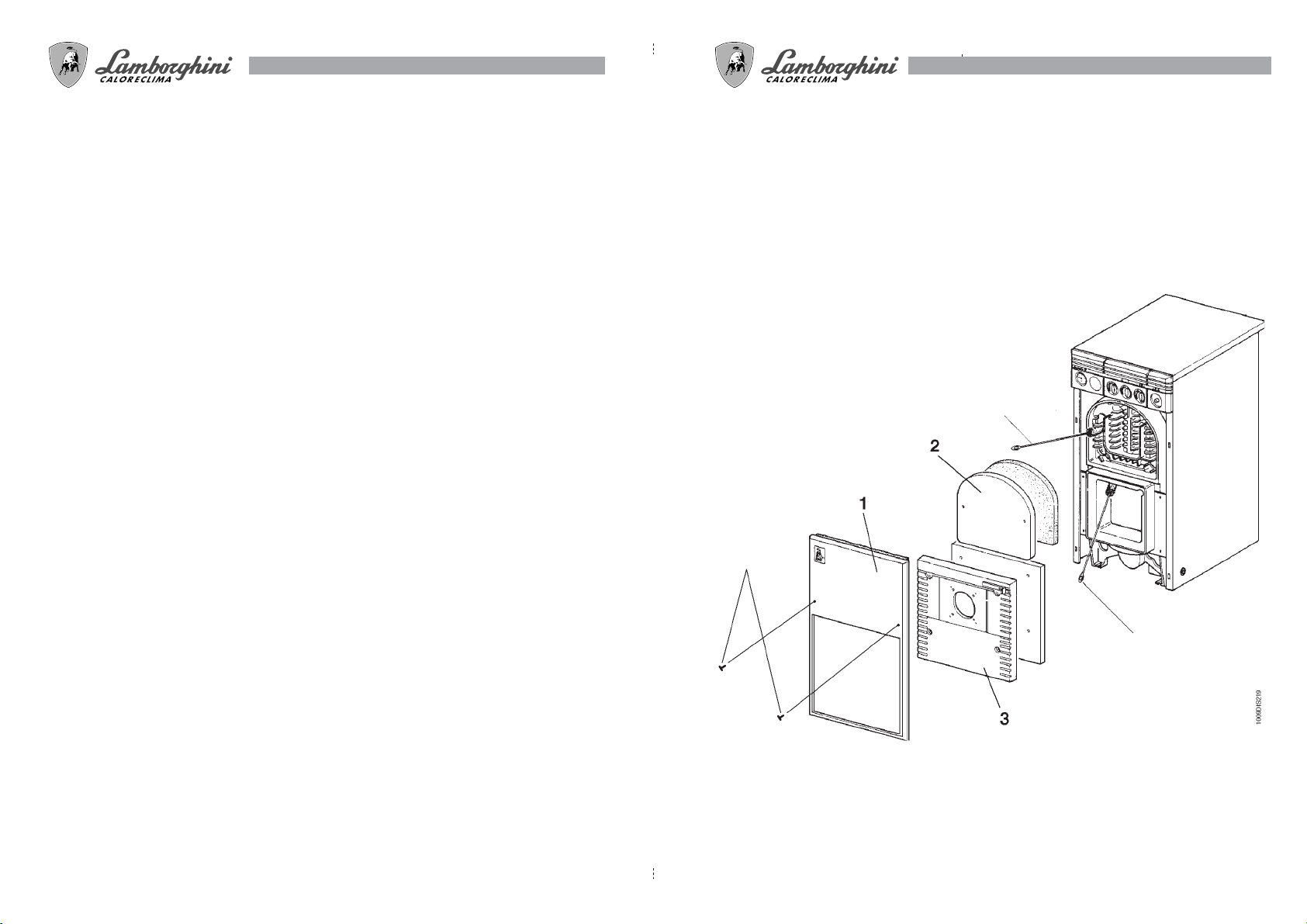
PULIZIA DELLA CALDAIA
● Togliere corrente alla caldaia;
● togliere i pannelli 1,2 e 3 (Fig. 8);
● pulire quindi l’interno della caldaia;
● controllare tutto il condotto dei fumi e,
se necessario, pulirlo.
Per la pulizia del bruciatore consultare il relativo
libretto istruzioni.
ABSCHALTEN
Für kurze Standzeiten ist es ausreichend, den Ein/Ausschalter (Abb. 2) auf dem Armaturenbrett auszuschalten. Für lange Standzeiten in der Heizperiode (Winter) muß der Anlage entweder ein Frostschutzmittel
zugeführt oder die Anlage vollständig geleert werden.
REGELMÄßIGE KONTROLLEN
Die Kesselwartung muß von qualifiziertem Fachpersonal durchgeführt werden. Wenigsten einmal pro Jahr
vor der Heizperiode soll das Gerät überprüft werden. Bei dieser Kontrolle muß außer der Reinigung des
Kessels auch die überprüfung der Funktionstüchtigkeit aller Kontroll-und Sicherheitsvorrichtungen, sowie
die des Brenners durchgeführt werden. Weiters muß die Abgasführung kontrolliert werden und sichergestellt werden, daß der gesamte Abgasweg sauber ist.
Fig. 8

14
67
SCHEMA DI PRINCIPIO SEC 30 + BVE
IG
L
LEGENDA
B Bruciatore
CiB Circolatore bollitore
CiR Circolatore
riscaldamento
EI Interruttore ESTATE/
INVERNO
IG Interruttore generale
3
SF
SB Spia di blocco
SF Spia di funzionamento
TA Termostato ambiente
TB Te rmostato bollitore
TR Te rmostato di
regolazione
TS Te rmostato di
sicurezza
TP Te r mostato
precedenza
N
SB
ANSCHLUSSSCHEMA SEC 30
1
4
C
1
2
TP
3
4
C
BIANCO
3
2
1
TR
C
C
TS
2
B
6
4
TA
5
BLU
5
6
8
CiR
7
ROSSO
2
5
6
EI
1
2
1009DIS1200
2
Fig. 10
TB
1
Zur installation des Boilers,
6-poligen Stecker entfernen
CiB
PRINZIPSCHEMA SEC 30
6-polige Steckverbindung
Kabel 4x1 mmq PVC-HT
Geräteanschluß
Brennerkontrolle
L
3
N
U
RZ
A
BRA
W
H
SC
GELB/GRUN
U
ELLBLA
H
IG
SF
BRAUN
Kabel 3x1 mmq PVC-HT
HELLBL.
Stromversorgung 220 Vac
GELB/G.
Abb. 6
1
3
4
2
1
TR
C
C
TS
2
6
4
TA
5
5
1009DIS1199
A= 900 (Abbinamento con BVE 80)
A= 1050 (Abbinamento con BVE 120)
Fig. 11
LEGENDE
B Brenner
SF Betriebslampe
CBr Brenneranschluß
TA Raumthermostat (eventuel)
CBol Kabelverbinder Boiler
B
SB
N
6
7
2
Heizungsumlauf
Abb. 7
8
TR Regelthermostat
IG Hauptschalter
TS Sicherheitstemperaturwächter
SB Störlampe

CiR
VR
S
B
CALDAIA
CiB
BOLLITORE
SCARICO
RUBINETTO
DI UTILIZZO
ACQUEDOTTO
1009DIS223
VS
VE
VS
66
15
INSTALLATION
Die Aufstellung des Kessels darf nur durch qualifiziertes Fachpersonal unter Einhaltung der Angaben des
Herstellers und Beachtung aller entsprechenden Gesetze und Vorschriften erfolgen.
Man weist hier vor allem auf das Einhalten der Sicherheitsvorschriften und der Vorschriften für die Abgasführung hin.
HYDRAULIKANSCHLUSS
Die Hydraulikanschlüsse nach den jeweiligen Angaben auf den einzelnen Anschlüssen und entsprechend
der Abb.1 des vorliegenden Handbuches herstellen. Der Anschluß muß so erfolgen, daß die Rohre spannungsfrei verlaufen. Auf den Heizungskreislauf, in nächster Nähe des Kessels, muß ein Sicherheitsventil montiert
werden, wobei zwischen Kessel und Sicherheitsventil keine weiteren Absperrorgane liegen dürfen.
Der Kessel wird ohne Ausdehnungsgefäß geliefert; es ist daher Aufgabe des Installateurs, ein solches zu montieren. Hinweis: der Anlagenbetriebsdruck bei kalter Anlage muß zwischen 0,5 und 1,5 bar
liegen.
SCHORNSTEINANSCHLUSS
Der Kessel muß an einen wirksamen Schornstein angeschlossen werden, der nach den gültigen Vorschriften gebaut wurde. Die Rohrleitung zwischen Kessel und Schornstein muß aus einem hitzbeständigen
und gegen Korrosion widerstandsfähigem Material sein. Die Verbindungsstellen sind gut abzudichten und über den gesamten Verlauf
zwischen Kessel und Schornstein gegen Wärmeverlust zu schützen,
um die Kondenswasserbildung zu verhindern.
ELEKTRISCHER ANSCHLUß - SCHALTPLÄNE
Die Pumpen, den Brenner und den eventuellen Raumthermostat nach
den beiliegenden Schaltplänen (Abb. 6/7) anschließen. Zwischen
Netz und Gerät ist ein zweipoliger Schalter anzuordnen, der eine
Öffnung der Kontakte von mindestens 3 mm aufweist und mit Sicherungen von max. 5A versehen ist.
Für jedeb elektrischen Anschluß die zur Ausstattung gehörenden
Kabeldurchgänge (schintop) verwenden.
Das Gerät muß außerdem an eine ausreichende Nulleitung angeschlossen werden. Die Firma Lamborghini weist jeden
Gewährleistungsanspruch wegen Schäden an Personen oder
Sachgut zurück, wenn das Gerät nicht an eine gute Nulleitung angeschlossen wurde.
Hinweis: Die Versorgungsleitung des Brenners (Pos. 1 Abb. 5) kann
je nach Erfordernis des Anlagenbetreibers rechts oder links angeordnet werden.
Abb. 5
Abb. 4
CIRCUITO IDRAULICO SEC 30 + BVE
Fig. 12
LEGENDA
B Bruciatore
CiB Circolatore bollitore
CiR Circolatore riscaldamento
S Saracinesca
VE Vaso espansione
VR Valvola antiritorno
VS Valvola di sicurezza

16
65
MONTAGGIO KIT OROLOGIO PROGRAMMATORE
Per l’installazione dell’orologio programmatore, togliere il tappo foro
orologio ed utilizzare le 4 viti di fissaggio fornite in dotazione
(Fig. 17). Per le connessioni elettriche, collegare i contatti 1 e 2 rispettivamente alla FASE ed al NEUTRO ed i contatti orologio 3 e 5 in serie
alla linea termostatica (Fig. 18).
Fig. 17
PROGRAMMAZIONE
Girando il disco programma in senso orario si posiziona l’ora del giorno come in un normale orologio. I
tempi di inserimento sono selezionabili, abbassando le astine mobili, al ritmo di 15 minuti per volta (ogni
astina mobile).
HAUPTBESTANDTEILE
ARMATURENBRETT SEC 30
Brennerstörlampe
Druckanzeige Heizung
Fester Drehknopf
Schaltuhr (auf Wunsch)
Betriebslampe
Kesselthermostat
Sicherheitsthermostat
Ein/Ausschalter
Abb. 2
morsetti di
collegamento
230 V - 50/60 Hz
interruttore
16 A - 250 V ~
Fig. 18
Il commutatore a levetta, posto in prossimità delle lancette, consente le seguenti tre possibilità:
1 con la levetta in posizione “I” si esclude il funzionamento della caldaia per il riscaldamento;
2 con la levetta in posizione “O” la caldaia rimane sempre in funzione per il riscaldamento, comandata
dai termostati caldaia e da quello ambiente;
3 con la levetta in posizione fra “I” e “O”, la caldaia funziona automaticamente per il riscaldamento,
secondo il programma impostato dall’Utente con le astine mobili.
1 Vorderglied
2 Mittelglied
3 Hinterglied
4 Doppelkegel
5 Kaminanschluß
6 Kessëltur zur Brenneraufnahme
Abb. 3
7 Kesselfürisolierung
8 Tür für Wartungseingriffe
9 Isolierung der Wartungstür
10 Entleerungshahn
11 Löche für kabelnpresse

TECHNISCHE DATEN
SEC 30
64
17
NUTZWÄRME-
LEISTUNG
NENNWÄRME-
LEISTUNG
NUTZWÄRMELEISTUNG
EINSTELLBAR BIS
SEGMENTANZAHL
KESSELINHALT
BRENNKAMMER LÄNGE
BRENNKAMMER ABMESS.
BETRIEBSßBERDRUCK
DRUCKVERLUST BRENNK.
BRENNKAMMERVOLUMEN
DRUCKVERLUST
WASSER
KESSELGEWICHT
Anmerkung: - Maximale Betriebstemperatur Heizungswasser 90 °C.
- Minimale Betriebstemperatur Heizungswasser 45 °C.
kW
kcal/h
kW
kcal/h
kW
kcal/h
lt
mm
mm
bar
∆p mbar
lt
∆t 10
∆t 20
kg
30,6
26300
34,0
29200
24,3
20900
3
14
386
260x310
4
0,10
20,15
1,8
105
FRANCAIS
F
Lire attentivement le mode d'emploi et les instructions du présent livret car ils fournissent
des indications de l'emploi et de la manutention.
Conserver avec soin ce livret pour ultérieures consultations.
L'installation doit être effectuée par un personnel qualifié qui sera responsable de respecter
les normes de sécurité en viguer.

ÍNDICE PÁGINA
GENERALITES 21
DIMENSIONS ET CARACTERISTIQUES TECHNIQUES 21
COMPOSANTS PRINCIPAUX 23
INSTALLATION 23
BRANCHEMENTS ELECTRIQUES ET SCHEMAS 23
VERIFICATIONS ET CONTROLES 25
ALLUMAGE ET EXTINCTION 24
ENTRETIEN PERIODIQUE 25
COMBINAISON CHAUDIERE-BALLON ECS 27
MONTAGE DU CAPOT D’ISOLATION ACOUSTIQUE 29
MONTAGE KIT HORLOGE PROGRAMMATEUR 30
18
63
BESCHREIBUNG
Die Baureihe SEC 30 ist ein hochleistungfähiger Wärmeerzeuger für die Beheizung von Wohn- und Industriegebäuden, die mit Brennern zur Feuerung von flüssigen und/oder gasförmigen Brennstoffen kombiniert
werden kann. Der Kesselkörper besteht aus Gußelementen, die durch Stahldoppelkegel und Stahlanker
verbunden sind. Bei der Entwicklung wurde besondere Aufmerksamkeit dem Profil des Kessels und der
Aufteilung der Flügel geschenkt, wodurch hohe Wärmeleistung mit folglich großer Energieersparnis erzielt
wurde. Die Formschönheit und die komplette Wärmeisolierung sind gegeben durch ein elegantes Armaturenbrett, eine lackierte Verkleidung, sowie einer dicken Glaswollisolierung, die den Wärmeverlust auf ein
Minimum reduzieren.
ABMESSUNGEN
Abb. 1
Toutes nos felicitations...
… vous avez fait le bon choix!
LAMBORGHINI garantit non seulement la qualité du produit, mais également l'efficience de son réseau
d'Assistance Technique.
CONTACTER, POUR TOUTES VOS
NECESSITES L'AGENCE "LAMBORGHINI" LA PLUS PROCHE.
Lire attentivement les instructions et les précautions contenues dans cette brochure car elles fournissent des
indications importantes sur la sécurité de l'installation, de l'utilisation et de la maintenance.
Conserver soigneusement et consulter cette brochure pour toutes vos nécessités.
L'installation doit être réalisée par un personnel qualifié qui sera responsable du respect des normes de
sécurité en vigueur.
a1
a2
a3
A
B
Ø
mm
mm
mm
SEC 30
Anlagenvorlauf 1 1/2"
Anlagenrücklauf 1 1/2"
Kesselentleerung 1/2"
420
105
130

Die Hochleistungs Gußkessel SEC haben die europäischen
Zulassungsprufüngen gut bestanden, und sind den
Einschränkungsnormen für die Sicherheit und
Wirkungsgrad entsprechend.
1962

Les chaudières en fonte à rendement élevé ont reussi les essais
d'homologation européens et elles sont conformes aux normes de
sécurité et rendement les plus restrictives.
20
61

INHALT SEITE
BESCHREIBUNG 63
ABMESSUNGEN UND TECHNISCHE DATEN 63
HAUPTBESTANDTEILE 65
INSTALLATION 66
ELEKTRISCHER ANSCHLUSS - SCHALTPLÄNE 66
CHECKLIST UND KONTROLLEN 68
ZÜNDUNG - ABSCHALTEN 68
REGELM-ßIGE WARTUNG 68
KOMBINATION KESSEL - SPEICHER 69
MONTAGE DES AKUSTIK-COVER SATZES 71
MONTAGE PROGRAMM-SCHALTUHR 72
60
21
GENERALITES
La série SEC 30 est un générateur de chaleur à haut rendement pour chauffage domestique ou industriel,
approprié au fonctionnement avec brûleurs de combustibles liquides et/ou gazeux.
Le corps de la chaudière est constitué d’éléments en fonte, assemblés par bicônes et tirants d’acier, dont le
profil a été particulièrement étudié, avec une répartition optimale des ailettes, permettant une grande efficacité
thermique et par conséquent une économie d’énergie importante.
L’esthétique et l’isolation complète sont assurées par un élégant tableau de bord, un habillage peint assemblé
par pression, et par un revêtement en laine de verre de grosse épaisseur qui réduit au minimum les
déperditions de chaleur dans le local.
DIMENSIONS
Fig. 1
Kompliment…
…für Ihre gute Wahl!
LAMBORGHINI garantiert nicht nur die Qualität des Produktes, sondern auch die Zuverlässigkeit ihres
technischen Kundendienstnetzes. IM BEDARFSFALL WENDEN SIE SICH BITTE AN DEN TECHNISCHEN
KUNDENDIENST LAMBORGHINI IN IHRER NÄHE.
Bitte lesen Sie die Anleitungen und Hinweise in dem vorliegenden Handbuch aufmerksam durch. Sie enthalten wichtige Informationen bezüglich Installation, Gebrauch und Wartung. Bewahren Sie dieses Handbuch
zum späteren Nachschlagen sorgfältig auf. Die Installation ist von qualifiziertem Fachpersonal unter Berücksichtigung der geltenden Sicherheitsvorschriften durchzuführen.
a1
a2
a3
A
B
Ø
mm
mm
mm
SEC 30
Dépant chauffage 1 1/2"
Retour chauffage 1 1/2"
Vidange chaudière 1/2"
420
105
130

CARACTERISTIQUES TECHNIQUES
PUISSANGE
THERMIQUE UTILE
PUISSANGE
THERMIQUE NOMINALE
PUISSANGE
UTILE RÉGLABLE JUSQU'À
N° ÉL.
CONTENU EAU
LONGUEUR CHAMBRE COMBUSTION
DIMENSIONS CHAMBRE COMBUSTION
PRESSION FONCTIONNEMENT
PERTE DE CHARGE CHAMBRE COMBUSTION
VOLUME CHAMBRE COMBUSTION
PERTE DE
CHARGE EN EAU
POIDS CORPS
kW
kcal/h
kW
kcal/h
kW
kcal/h
lt
mm
mm
bar
∆p mbar
lt
∆t 10
∆t 20
kg
SEC 30
30,6
26300
34,0
29200
24,3
20900
3
14
386
260x310
4
0,10
20,15
1,8
105
22
59
NOTA: - La température maximum de fonctionnement de l’eau de chauffage de l’installation est de 90 °C.
- La température minimum de fonctionnement de l’eau de chauffage de l’installation est de 45 °C.
DEUTSCH
D
Bitte lesen Sie die Anleitungen und Hinweise in dem vorliegenden Handbuch aufmerksam durch. Sie enthalten wichtige Informationen bezüglich Installation, Gebrauch und
Wartung. Bewahren Sie dieses Handbuch zum späteren Nachschlagen sorgfältig auf.
Die Installation ist von qualifiziertem Fachpersonal unter Berücksichtigung der geltenden Sicherheitsvorschriften durchzuführen.

58
23
ASSEMBLY OF PROGRAMMING CLOCK KIT
For the installation of the programming clock, remove the cap from the
clock hole and use the 4 fixing screws supplied with the kit (Fig. 17).
For the electrical wiring, connect the contacts 1 and 2 to PHASE and
NEUTRAL respectively and the clock contacts 3 and 5 in serie on the
thermostats line. (Fig. 18).
Fig. 17
PROGRAMMING
By turning the programme disc clockwise the day time can be adjusted as with a normal clock. The setting
times are selectable by lowering the adjustable levers for each 15 minutes (each lever).
COMPOSANTS PRINCIPAUX
TABLEAU DE BORD SEC 30
Lampe témoin de blocage brûleur
Thermomanomètre
Manette fixe
Horloge (sur demande)
Lampe témoin de fonctionnement
Thermostat de réglage chaudière
Thermostat de sécurité
Interrupteur Marche/Arrêt
Fig. 2
connection
terminals
230 V 50/60 hz
switch
16 A - 250 V
Fig. 18
The levered switch, situated close to the pointer needles, allows the following three possibilities:
1 with the lever on “I” position the heating operation of the boiler is excluded;
2 with the lever on “O” position the boiler remains in continuous heating operation, controlled by the
boiler thermostats and the room thermostat;
3 with the lever between “I” and “O” positions, the boiler automatically operates for heating, according
to the programme set up by the User with the adjustable levers.
1 Elément avant
2 Elément intermédiaire
3 Elément arrière
4 Nipple
5 Prise de raccordement carneau
6 Plaque porte brûleur
Fig. 3
7 Isolant plaque porte brûleur
8 Volet de nettoyage
9 Isolant volet de nettoyage
10 Robinet de vidange
11 Trous pour serre-câbles

24
57
INSTALLATION
L’installation de la chaudière ne doit être faite que par un personnel qualifié, suivant les instructions du
constructeur et dans le respect de toutes les normes légales en la matière.
Il est recommandé de façon toute particulière de respecter les règles de sécurité ainsi que celles régissant la
construction et l’implantation des carneaux montants.
RACCORDEMENT HYDRAULIQUE
Effectuer le raccordement hydraulique de l’appareil en respectant les indications situées à côté de chaque
prise de raccordement ainsi que celles de la fig. 1 de cette notice.
Le raccordement doit être réalisé de manière à ne pas créer de tension sur les tuyaux. Il est obligatoire de
monter une soupape de sécurité sur le circuit de chauffage, à un endroit le plus proche possible de la
chaudière, sans interposer d’obstacles ou organes d’arrêt entre cette soupape et la chaudière.
L’appareil n’est pas équipé de vase d’expansion. Son raccordement
est donc a faire exécuter par l’installateur.
Nous rappelons à ce propos que la pression de l’installation, à froid,
doit être comprise entre 0,5 et 1,5 Bars.
RACCORDEMENT AU CARNEAU MONTANT
Il est recommandé de raccorder la chaudière à un carneau montant
de bonne qualité réalisé dans le respect des normes en vigueur.
Le conduit reliant la chaudière et le carneau montant doit être réalisé
en matériau prévu à cet effet, c’est à dire résistant à la température et
à la corrosion.
Aux niveau des points de jonction, nous recommandons de soigner
particulièrement l’étanchéité et d’isoler thermiquement tout le conduit
entre chaudière et carneau afin d’éviter la formation de condensation.
Fig. 4
BRANCHEMENTS ELECTRIQUES ET SCHEMAS
Effectuer les branchements des pompes, du brûleur et du
thermostat d’ambiance éventuel en respectant les indications du
schéma en annexe (Fig. 6/7).
Nous recommandons d’installer un interrupteur bipolaire entre
le réseau et l’appareil avec ouverture des contacts minimum de
3 mm et fusibles de 5 A max.
Pour chaque connexion électrique, utiliser les serre-câbles en dotation.
SEC 30 + BVE HYDRAULIC CIRCUIT
VR
VS
CiR
1009DIS223
B
CALDAIA
CYLINDER
LEGEND
B Burner
CiB Cylinder circulating pump
CiR Heating circulating pump
S Gate valve
VE Expansion tank
VR Non-return valve
VS Safety valve
VE
S
VS
CiB
BOILER
BOLLITORE
SCARICO
WASTE
TAP FOR USE
RUBINETTO
DI UTILIZZO
ACQUEDOTTO
WATER MAIN
SUPPLY
Fig. 12
Nous recommandons en outre la mise à la terre parfaite de
l’installation.
Lamborghini Calor SpA décline toute responsabilité en cas
de dommage aux personnes ou aux biens dérivant de
l’absence de branchement de l’installation à un bon dispositif
de mise à la terre.
NB: Le câble brûleur (Pos. 1 Fig. 5) peut être positionné, selon
les exigences de l’utilisateur, à droite ou à gauche.
Fig. 5

56
25
SEC 30 + BVE PRINCIPLE SCHEME
L
LEGEND
B Burner
CiB Cylinder circulating pump
CiR Heating circulating pump
EI SUMMER/WINTER switch
IG Main switch
SB Lock-out warning light
3
SF Operating indicator
TA Room thermostat
TB Cylinder thermostat
TR Adjustment thermostat
TS Safety thermostat
TP Priority thermostat
N
SF
SCHEMA DE BRANCHEMENT SEC 30
IG
1
3
4
2
1
TR
C
C
TS
2
B
SB
BROWN
4
C
1
2
TP
WHITE
C
3
6
4
TA
5
5
6
BLUE
5
6
8
7
2
1
CiR
RED
2
EI
1009DIS1200
TB
1
2
CiB
Mas. 6 Poles
iner le connecteur
élim
Pour l'installation du bruleur,
SCHEMA DE PRINCIPE SEC 30
Fig. 10
Femm. 6 Poles
CABLE 4x1 mm2 PVC-HT
CONNEXION ÉQUIPMENT
CONTROLE BRULEUR.
L
3
MARRON
NOIR
BLEU
JAUNE/V.
MARR.
CABLE 3x1 mm2 PVC-HT
BLUE
J./V.
ALIMENTATION DE
RÉSEAU 220 VAC
Fig. 6
IG
1
3
4
2
1
TR
C
C
TS
SF
2
6
4
TA
5
5
1009DIS1199
A= 900 (Combination with BVE 80)
A= 1050 (Combination with BVE 120)
Fig. 11
LÉGENDE
B Brûleur
CBr Connexion brûleur
CBol Connecteur bouilleur
IG Interrupteur général
SB Témoin de blocage
B
SB
N
6
Groupe conduits
7
de chauffage
2
Fig. 7
8
SF Témoin de fonctionnement
TA Thermostat d’ambiance (eventuel)
TR Thermostat de réglage
TS Thermostat de sécurité

26
55
VERIFICATIONS ET CONTROLES
AVANT L’ALLUMAGE INITIAL
Avant l’allumage initial, il est conseillé de vérifier les éléments suivants:
a L’installation est remplie à la bonne pression et bien purgée;
b Absence de fuites d’eau ou de combustible;
c L’alimentation électrique est correcte;
d Tous les conduits de fumée sont réalisés correctement, à distance des parties inflammables, et ne les
traversent pas;
e Absence de substances inflammables dans le voisinage de l’appareil;
f Le brûleur est proportionné à la puissance de la chaudière;
g Les soupapes d’arrêt d’eau sont ouvertes;
APRES L’ALLUMAGE INITIAL
Après l’allumage initial il est conseillé de contrôler que:
● Le brûleur fonctionne correctement.
Ce contrôle doit être fait avec les instruments appropriés;
● Les thermostats fonctionnent de façon correcte;
● L’eau circule dans l’installation;
● L’évacuation des fumées se fait complètement par le conduit.
ALLUMAGE ET EXINCTION
ALLUMAGE INITIAL
Une fois les contrôles préliminaires effectués, il est possible de procéder aux manoeuvres d’allumage suivantes:
1 Ouvrir la soupape d’arrêt de combustible (éventuelle);
2 Régler le thermostat chaudière (Fig. 2) sur la valeur désirée;
3 Fermer l’interrupteur en amont de la chaudière et l’interrupteur Marche/Arrêt (Fig. 2) installé sur le
tableau de commande.
EXTINCTION
Pour des périodes d’interruption assez brèves, il suffit d’actionner l’interrupteur Marche/Arrêt (Fig. 2) situé
sur le tableau de commande.
Pour les arrêts de longue durée en période hivernale, afin d’éviter des dommages causés par le gel, introduire
l’antigel prévu à cet effet dans l’installation ou vider celle-ci complètement.
BOILER CLEANING
● Switch the current off the boiler;
● Remove the panels 1, 2 and 3 (Fig. 8);
● Then clean the inside of the boiler;
● Check all the smoke duct and, if necessary,
clean it.
For cleaning the burner consult the related instruction booklet.
Cylindrical brush for cleaning
Screws
Cylindrical brush for cleaning
Fig. 8
ENTRETIEN PERIODIQUE
L’entretien de la chaudière doit être effectué par un personnel qualifié.
Il est de bonne norme de faire contrôler l’appareil au moins une fois par an avant la saison hivernale.
Ce contrôle doit être effectué, outre l’état de propreté de la chaudière, également sur le fonctionnement
correct de tous ses dispositifs de contrôle et de sécurité ainsi que du brûleur.
L’état de tous les conduits d’évacuation des fumées doit également être contrôlé.

54
27
CHECKS AND CONTROLS
PRIOR TO THE INITIAL STARTING UP
Before the initial starting up, it is a good rule to check that:
a the system is refilled to the correct pressure and well purged;
b there are not any leakages of water or fuel;
c the electrical supply is correct;
d all the smoke conduit has been installed properly and is not too close or crosses inflammable parts;
e there are not any inflammable substances in proximity of the appliance;
f the burner is in proportion to the boiler output;
g the water interception valves are open.
AFTER THE INITIAL STARTING UP
After the first starting up it is a good rule to check that:
● the burner functions properly.
This check must be made with the appropriate tools;
● the thermostats function correctly;
● the water circulates in the system;
● the smoke evacuation is effected exclusively through the chimney.
STARTING UP - SWITCHING OFF
INITIAL STARTING UP
After carrying out the preliminary checks,it is possible to proceed with the following starting operations:
1 open the fuel interception valve (if any);
2 adjust the boiler thermostat (Fig. 2) to the desired value;
3 shut off the upstream switch on the boiler and the on/off switch (Fig. 2) situated on the control panel.
NETTOYAGE DE LA CHAUDIERE
● Couper l’alimentation électrique de la chaudière;
● Retirer les panneaux 1,2 et 3 (Fig. 8);
● Nettoyer ensuite l’intérieur de la chaudière;
● Contrôler tous les conduits de fumées et les
nettoyer le cas échéant.
Pour le nettoyage du brûleur consulter la notice
d’instruction relative.
Ecouvillon de nettoyage
Vis
Ecouvillon de nettoyage
SWITCHING OFF
For brief periods of rest it is sufficient to use the on/off switch (Fig. 2) situated on the control panel.
For long rest periods during the winter period, in order to avoid damages caused by freezing, it is necessary to introduce the appropriate anti-freeze fluid into the system or otherwise empty the latter completely.
PERIODICAL MAINTENANCE
The maintenance of the boiler must be carried out by Qualified Personnel.
It is a good rule to have a check of the appliance carried out at least once a year, before the winter season.
Such a check should concern, besides the condition of cleanliness of the boiler, the correct functioning of all
its control and safety devices as well as the burner itself.
In addition the state of the smoke exhaust should be checked.
Fig. 8

28
53
SCHEMA DE PRINCIPE SEC 30 + BVE
L
LÉGENDE
B Brûleur
CiB Pompe de charge ECS
3
CiR Pompe chauffage
EI Interrupteur ETE/HIVER
IG Interrupteur général
SB Témoin de blocage
SF Témoin de
fonctionnement
TA Thermostat d’ambiance
TB Thermostat ballon ECS
TR Thermostat de réglage
TS Thermostat de sécurité
N
TP Thermostat priorité
WIRING DIAGRAM SEC 30
IG
1
1
3
4
2
1
TR
C
C
TS
SF
2
B
SB
MARRON
2
TP
C
6
4
TA
5
5
6
8
7
ROUGE
2
BLANC
BLEU
CiR
4
C
TB
1
2
3
5
6
CiB
EI
1
ale connector
o install the boiler, discard
the 6-pin m
T
PRINCIPLE SCHEME SEC 30
2
1009DIS1200
6-pin female
4x1 mmq PVC-HV CABLE
CONNECTING THE BURNER
CONTROL EQUIPMENT
L
BROWN
BLACK
YELLOW/G.
L. BLUE
IG
BROWN
3x1 mmQ PVC-HV CABLE
L.BLUE
POWERED FROM THE
Y./G.
220 V a.c. mains
Fig. 6
1
Fig. 10
3
4
2
1
TR
C
C
3
SF
TS
2
6
4
TA
5
5
1009DIS1199
A= 900 (combinaison avec BVE 80)
A= 1050 (combinaison avec BVE 120)
Fig. 11
LEGEND
B Burner
CBr Burner connection
CBol Boiler connector
IG Main switch
SB Lock-out warning light
B
SB
N
6
8
Heating
circulation
7
2
Fig. 7
SF Operating indicator
TA Room thermostat (if present)
TR Adjustment thermostat
TS Safety thermostat

CiR
VR
S
B
CALDAIA
CiB
BOLLITORE
SCARICO
RUBINETTO
DI UTILIZZO
ACQUEDOTTO
1009DIS223
VS
VE
VS
52
29
INSTALLATION
The installation of the boiler must only be carried out by Qualified Personnel, following the indications of the
Manufacturer and in compliance with all the laws and regulations which control the subject. It is particularly
recommended that the regulations in the matter of safety are observed and those that regulate the construction and location of the flue pipes.
HYDRAULIC CONNECTION
Carry out the hydraulic connection of the appliance complying with the directions placed close to each
connection and the ones related in figure 1 of this booklet. The connection must be made so that the pipes
are free from tension and it is compulsory to assemble a safety valve on the heating circuit, at a point as
near as possible to the boiler, without there being, between said boiler and valve, any obstruction or
intercepting device.
The appliance is not equipped with the expansion tank; its connection therefore must be carried out by the installer. For such purpose
we remind that the system pressure, when cold, must be between 0.5
and 1.5 bars inclusive.
CONNECTION TO THE FLUE PIPE
It is advised to connect the boiler to a sound flue pipe, built in compliance with the current regulations. The conduit between the boiler and
the flue must be made from a material suitable for this purpose or
else resistant to temperature and corrosion. At the junction points it is
advisable to cure the tightness and thermally insulate all the conduit
between boiler and chimney in order to avoid the formation of condensation.
Fig. 4
WIRING DIAGRAMS
Carry out the connection of the circulating pump, the burner and the
possible room thermostat by observing the directions in the diagrams
attached (Fig.s 6 & 7). It is recommended to interpose a bipolar switch
between the power supply and the appliance, with contact openings
of at least 3 mm, provided with fuses of 5 A max.
Use the cable grips supplied for all electrical connections.
In addition it is advisable to connect the appliance to a sound earthing system.
Lamborghini Calor s.p.a, declines any responsibility for damage to
persons or things caused by the non-connection of the appliance to
a sound earthing system.
CIRCUIT HYDRAULIQUE SEC 30 + BVE
CHAUDIERE
LÉGENDE
B Brûleur
CiB Pompe de charge
CiR Pompe chauffage
S Vanne
VE Vase d’expansion
VR Clapet anti-retour
VS Soupape de sécurité
BALLON
VIDANGE
ROBINET
DE PUISAGE
RÉSEAU DE
DISTRIBUTION D’EAU
Fig. 12
N.B.: The burner cable (Pos. 1 Fig. 5) can be positioned, according
to the necessity of the user, to the right or the left.
Fig. 5

30
51
MONTAGE KIT HORLOGE PROGRAMMATEUR
Pour l’installation de l’horloge programmateur, retirer le bouchon du
trou horloge et utiliser les 4 vis de fixation fournies de série (Fig.17).
Pour les connexions électriques, relier les contacts 1 et 2 respectivement
à la phase et au neutre, et les contacts horloge 3 et 5 à la ligne
thermostatique (Fig.18).
Fig. 17
PROGRAMMATION
En tournant le disque programme dans le sens des aiguilles d’une montre, on sélectionne l’heure du jour
comme pour une montre normale.
Les temps d’insertion peuvent être sélectionnés en abaissant les tiges mobiles par tranches de 15 minutes à
la fois (une tranche par cavaliers mobile).
MAIN COMPONENTS
SEC 30 INSTRUMENT PANEL
Burner lock-out warning light
Thermohydrometer
Fix knob
Clock (on request)
Operation indicator
Boiler adjustment thermostat
Safety thermostat
ON/OFF switch
Fig. 2
Bornes de
branchement
230 V-50/60 Hz
Interrupteur
16 A-250 V ~
Fig. 18
Le commutateur à levier situé à proximité des aiguilles permet les trois possibilités suivantes:
1 Levier en position “I”, le fonctionnement de la chaudière pour le chauffage est exclus.
2 Levier en position “O”, la chaudière est en fonctionnement permanent pour le chauffage, commandée
par les thermostats chaudière et le thermostat d’ambiance.
3 Levier en position entre “I” et “O”, la chaudière fonctionne automatiquement pour le chauffage selon
le programme sélectionné par l’utilisateur par le biais des cavaliers mobiles.
1 Front element
2 Middle element
3 Rear element
4 Bicone
5 Flue connection
6 Burner-holding door
Fig. 3
7 Door insulating gasket
8 Door for cleaning
9 Door insulating gasket
10 Draining cock
11 Holes for cable grip

TECHNICAL FEATURES
SEC 30
50
31
USEFUL THERMAL
DELIVERY
NOMINAL THERMAL
DELIVERY
USEFUL DELIVERY
ADJUSTABLE UP TO
ELEMENTS Q.TY
WATER CONTENT
COMBUSTION CHAMBER LENGTH
COMBUSTION CHAMBER DIMENSIONS
OPERATING PRESSURE
COMBUSTION CHAMBER PRESSURE DROP
COMBUSTION CHAMBER VOLUME
WATER CONTENT
DROP
BODY WEIGHT
NOTE: - Maximum operating temperature of the system heating water is 90 °C.
- Minimum operating temperature of the system heating water is 45 °C.
kW
kcal/h
kW
kcal/h
kW
kcal/h
lt
mm
mm
bar
∆p mbar
lt
∆t 10
∆t 20
kg
26300
29200
20900
260x310
20,15
30,6
34,0
24,3
3
14
386
4
0,10
1,8
105
ESPANOL
ES
Leer atentamente las instrucciones y las advertencias que contiene el presente folleto ya
que dan indicaciones importantes relativas a la seguridad de la instalación, al uso y al
mantenimiento.
Conservar con cuidado este folleto para cualquier ulterior consulta.
La instalación debe ser efectuada por personal cualificado que tendrá la responsabilidad
de respetar las normas de seguridad vigentes.
Las partes del embalaje ( bolsas de plástico, espuma de poliestirol, etc... ) no hay que
dejarlas al alcance de los niños ya que son potenciales fuentes de peligro.
Leer atentamente y conservar los cupones de garantía.

ÍNDICE PÁGINA
NOCIONES GENERALES 35
DIMENSIONES Y CARACTERÍSTICAS TÉCNICAS 35
COMPONENTES PRINCIPALES 37
INSTALACIÓN 38
CONEXIONES ELÉCTRICAS - ESQUEMAS 38
COMPROBACIONES Y CONTROLES 40
PUESTA EN MARCHA - PARADA 40
MANTENIMIENTO PERIÓDICO 40
ACOPLAMIENTO CALDERA - ACUMULADOR 41
MONTAJE EQUIPO ACOUSTIC COVER 43
MONTAJE EQUIPO RELOJ PROGRAMADOR 44
32
49
GENERAL INSTRUCTIONS
The SEC 30 series is a highly-efficient boiler for domestic and industrial heating, suitable for operation with
burners of liquid and/or gas fuels.
The boiler body is comprised of cast iron elements, assembled with steel bicones and ties, whose profile has
been specially cured with an optimal distribution of flaps allowing high thermal effectiveness and consistently high energy savings.
The aesthetic and complete insulation are ensured by an elegant instrument panel, a painted casingt pressure-assembled and a glasswool lining of considerable thickness, reducing the dispersion of heat into the
atmosphere to a minimum.
DIMENSIONI
Fig. 1
Felicitationes...
…por la óptima elección
La LAMBORGHINI garantiza no solo la calidad del producto sino también la eficencia de su red de
asistencia técnica. Para cualquier necesidad dirigirse a la agencia LAMBORGHINI màs cercana.
Leer atentamente las instrucciones y las advertencias que contiene el presente folleto ya que dan indicaciones
importantes relativas a la seguridad de la instalación, al uso y al mantenimiento.
Conservar con cuidado este folleto para cualquier ulterior consulta.
La instalación debe ser efectuada por personal cualificado que tendrá la responsabilidad de respetar las
normas de seguridad vigentes.
Las partes del embalaje ( bolsas de plástico, espuma de poliestirol, etc... ) no hay que dejarlas al alcance de
los niños ya que son potenciales fuentes de peligro.
Leer atentamente y conservar los cupones de garantía.
a1
a2
a3
A
B
Ø
mm
mm
mm
SEC 30
System delivery 1 1/2 ins.
System return 1 1/2 ins.
Boiler waste 1/2 ins.
420
105
130

SEC cast iron boiler for high efficiency have passed European
tests and comply with the strietest safety and efficiency regulation.
3348

Las calderas de hierro fundido de alto rendimento SEC han
superado los test europeos de homologación y respetan las
normas más restrictivas por lo que rspecta la
seguridad y el rendimiento.
34
47

INDEX PAGE
GENERAL INSTRUCTIONS 49
DIMENSIONS AND TECHNICAL FEATURES 49
MAIN COMPONENTS 51
INSTALLATION 52
WIRING DIAGRAMS 52
CHECKS AND CONTROLS 54
STARTING UP - SWITCHING OFF 54
PERIODICAL MAINTENANCE 54
BOILER - CYLINDER COMBINATION 55
ASSEMBLY OF ACOUSTIC COVER KIT 57
ASSEMBLY OF PROGRAMMING CLOCK KIT 58
46
35
NOCIONES GENERALES
La serie SEC 30 es un generador de calor de alto rendimiento para la calefacción de la casa o industrial,
adecuado para funcionar con quemadores de combustibles líquidos y/o gaseosos.
El cuerpo de la caldera está formado por elementos de hierro fundido, ensamblados con biconos y tirantes
de acero, cuyo perfil se ha cuidado especialmente con una distribución de las aletas, que permite una alta
eficacia térmica y como consecuencia un alto ahorro energético.
La estética y el total aislamiento están asegurados por un elegante panel de manejo, por una capa esmaltada
ensamblada a presión y por un revestimiento con lana de vidrio de grueso espesor que reduce al mínimo
las dispersiones de calor hacia el ambiente.
DIMENSIONES
Fig. 1
Congratulations…
…on an excellent choice!
LAMBORGHINI guarantees his products quality , and also the efficiency of his technical after-sale service network.
FOR ANY NECESSITY CALL THE NEAREST LAMBORGHINI AGENCY.
Read carefully all warnings and instructions contained in this manual as they give important safety instructions regarding installation, use and maintenance. Keep this manual for future reference. Installation must
be carried out by qualified personnel who will be responsible for respecting existing safety regulations.
a1
a2
a3
A
B
Ø
mm
mm
mm
SEC 30
Ida instalación 1 1/2"
Retorno instalación 1 1/2"
Descarga caldera 1/2"
420
105
130

CARACTERÍSTICAS TÉCNICAS
CAPACIDAD
TÉRMICA ÚTIL
CAPACIDAD
TÉRMICA NOMINAL
CAPACIDAD
ÚTIL REGULABLE HASTA
N° EL
CONTENIDO AGUA
LONGITUD CÁM. COMB.
LONGITUD CÁM. COMB.
PRESIONES DE UTILIZACION
PÉRD.CARGA CÁM. COMB.
VOLUMEN CÁM. COMB.
PÉRDIDAS DE CARGA DE
AGUA
PESO CUERPO
kW
kcal/h
kW
kcal/h
kW
kcal/h
lt
mm
mm
bar
∆p mbar
lt
∆t 10
∆t 20
kg
SEC 30
30,6
26300
34,0
29200
24,3
20900
3
14
386
260x310
4
0,10
20,15
1,8
105
36
45
NOTA: - La temperatura máxima de utilización del agua de la calefacción de la instalación es de90 °C.
- La temperatura mínima de utilización del agua de la calefacción de la instalación es de 45 °C.
ENGLISH
GB
Read carefully all warnings and instructions contained in this manual as they give
important safety instructions regarding installation, use and maintenance. Keep
this manual for future reference. Installation must be carried out by qualified
personnel who will be responsible for respecting existing safety regulations.

44
37
MONTAJE EQUIPO RELOJ PROGRAMADOR
Para instalar el reloj programador hay que quitar el tapón del agujero
del reloj y utilizar los 4 tornillos de sujeción suministrados con el equipo
(Fig. 17). Para realizar las conexiones eléctricas, unir los contactos 1 y
2 respectivamente a la FASE y al NEUTRO y los contactos del reloj 3 y
5 en serie a la línea termostática (Fig. 18).
Fig. 17
PROGRAMACIÓN
Girando el disco programa en sentido horario se pone la hora del día como en un reloj normal. El tiempo
que se quiere poner se puede seleccionar, bajando las levas móviles, a un ritmo de 15 minutos cada vez
(cada leva móvil).
COMPONENTES PRINCIPALES
PANEL SEC 30
Luz indicadora del bloqueo del quemador
Te rmohidrómetro
Manecilla fija
Reloj ( bajo demanda )
Luz indicadora del funcionamiento
Te rmostato regulación caldera
Termostato de seguridad
Interruptor encendido-apagado
Fig. 2
bornes de conexión
230V - 50/60 Hz
interruptor
16A - 250V~
Fig. 18
El conmutador con palanquita, colocado cerca de las agujas, permite las tres posibilidades siguientes:
1 con la palanquita en la posición “l” se excluye el funcionamiento de la caldera para la calefacción;
2 con la palanquita en posición “O” la caldera se mantiene siempre en funcionamiento para la calefacción,
accionada por los termostatos de la caldera y por el de ambiente;
3 con la palanquita en una posición entre “l” y “O”, la caldera funciona automáticamente para la
calefacción, según el programa que haya puesto el Usuario con las levas móviles.
1 Elemento anterior
2 Elemento intermedio
3 Elemento posterior
4 Bicono
5 Junta chimenea
6 Puertecita portaquemador
Fig. 3
7 Aislante puertecita portaquemador
8 Puertecita para la limpieza
9 Aislante puertecita limpieza
10 Grifo de desagüe
11 Agujeros para los aprietacables

38
CiR
VR
S
B
CALDAIA
CiB
BOLLITORE
SCARICO
RUBINETTO
DI UTILIZZO
ACQUEDOTTO
1009DIS223
VS
VE
VS
43
INSTALACIÓN
La instalación de la caldera debe ser efectuada sólo por Personal Cualificado, siguiendo las indicaciones
del Constructor y respetando todas las leyes y disposiciones que regulan la materia. Se recomienda de
manera particular el respeto de las normas por lo que respecta a la seguridad así como las que regulan la
construcción y la ubicación de las chimeneas.
EMPALME HIDRÁULICO
Hay que realizar el empalme hidráulico de la caldera respetando las indicaciones que se encuentran cerca
de cada junta y las que se encuentran en la figura 1 de este folleto. El empalme tiene que realizarse de
manera que los tubos estén libres de tensiones y es obligatorio montar la válvula de seguridad en el circuito
de calefacción, en un punto lo más cerca posible de la caldera, sin que haya entre ésta y la válvula ninguna
obstrucción u órgano de interceptación.
La caldera no se suministra con el tanque de expansión; por lo tanto
se tiene que encargar de acoplarlo el instalador. Con este propósito
recordamos que la presión de la instalación, en frío, tiene que estar
comprendida entre 0,5 y 1,5 bar.
UNIÓN A LA CHIMENEA
Se recomienda unir la caldera a una buena chimenea, que se haya
construido respetando las leyes vigentes. El conducto entre la caldera
y la chimenea tiene que ser de un material adecuado es decir, que
sea resistente a la temperatura y a la corrosión. En los puntos de
juntura se recomienda prestar atención al sellado y aislar
térmicamente todo el conducto entre la caldera y la chimenea con el
fin de evitar la formación de vapor de condensación.
Fig. 4
CONEXIONES ELÉCTRICAS - ESQUEMAS
Realizar las conexiones de las bombas de circulación del
quemador y del eventual termostato ambiente, respetando las
indicaciones de los esquemas adjuntos (Fig. 6/7). Se recomienda
interponer entre la red y la caldera un interruptor bipolar, con
una abertura de los contactos de al menos 3mm., equipado con
fusibles de 5A máx.
Utilisen para cada conexion eléctraca los aprieta çables que se
entregar con el equipo.
Se recomienda además conectar la caldera a un buen sistema
de tierra.
Lamborghini Calor s.p.a. se exime de toda responsabilidad
por los daños causados a personas o a cosas, por no haber
conectado el aparato a un buen sistema de tierra.
CIRCUITO HIDRÁULICO SEC 30 + BVE
CALDERA
DESCRIPCIÓN
B Quemador
CiB Bomba de circulación del acumulador
CiR Bomba de circulación de la calefacción
S Válvula
VE Tanque de expansión
VR Válvula de no retorno
VS Válvula de seguridad
ACUMULADOR
DESCARGA
GRIFO DE
UTILIZACIÓN
ACUEDUCTO
Fig. 12
Nota: El cable del quemador (Pos. 1 Fig. 5) se puede colocar
según la necesidad del usuario, a la derecha o a la izquierda.
Fig. 5

42
39
ESQUEMA DE PRINCIPIO SEC 30 + BVE
L
DESCRIPCIÓN
B Quemador
CiB Bomba de circulación
del acumulador
CiR Bomba de circulación
de la calefacción
EI Interruptor VERANO/
INVIERNO
IG Interruptor general
SB Luz indicadora del
3
bloqueo
SF Luz indicadora del
funcionamiento
TA Termostato ambiente
TB Te rmostato del
acumulador
TR Te rmostato de
regulación
TS Termostato de
seguridad
N
TP Te r mostato pecedencia
ESQUEMA DE CONEXIÓN SEC 30
IG
1
3
4
2
1
TR
C
C
TS
SF
2
B
SB
MARRON
1
2
TP
C
BLANCO
6
4
TA
5
5
6
8
7
2
TURQUI´
CiR
ROJO
4
C
TB
1
2
3
5
6
CiB
EI
1
2
1009DIS1200
vidor
er
Mas. 6 Polos
inar el conector
elim
Para la instalación del H
Femm. 6 Polos
CABLE 4x1 mm2 PVC-HT
CONEXION EQUIPO
CONTROL QUEMADOR.
ESQUEMA DE PRINCIPIO SEC 30
L
MARRON
NEGRO
AZUL
JAUNE/V.
MARR.
CABLE 3x1 mm2 PVC-HT
AZUL
ALIMENTACION DE
J./V.
RÉD 220 VAC
Fig. 6
IG
1
Fig. 10
3
4
2
1
TR
C
C
3
SF
TS
2
6
4
TA
5
5
1009DIS1199
A= 900 (Acoplamiento con BVE 80)
A= 1050 (Acoplamiento con BVE 120)
Fig. 11
DESCRIPCIÓN
B Quemador
CBr Conexion quemador
CBol Conector hervidor
IG Interruptor general
SB Luz indicadora del bloqueo
B
SB
N
6
Circulador de
7
calefacción
2
Fig. 7
8
SF Luz indicadora del funcionamiento
TA Termostato ambiente (eventual)
TR Te rmostato de regulación
TS Te rmostato de seguridad

40
41
COMPROBACIONES Y CONTROLES
ANTES DE LA PUESTA EN MARCHA INICIAL
Antes de la puesta en marcha inicial, es una buena costumbre controlar que:
a la instalación esté llena a la presión justa y haya salido todo el aire;
b no hayan pérdidas de agua o de combustible;
c la alimentación eléctrica sea correcta;
d toda la chimenea se haya realizado correctamente y que no esté demasiado cerca de partes inflamables
o las atraviese;
e no hayan sustancias inflamables cerca de la caldera;
f el quemador sea proporcional a la potencia de la caldera;
g las válvulas de interceptación de agua estén abiertas.
DESPUÉS DE LA PUESTA EN MARCHA INICIAL
Después de la primera puesta en marcha es una buena costumbre controlar que:
● el quemador funcione correctamente.
Este control hay que hacerlo con los instrumentos adecuados;
● los termostatos funcionen correctamente;
● el agua circule por la instalación;
● la evacuación de los humos tenga lugar completamente a través de la chimenea.
PUESTA EN MARCHA - PARADA
PUESTA EN MARCHA INICIAL
Una vez efectuados los controles preliminares, se puede pasar a las siguientes maniobras de encendido:
1 abrir la válvula de interceptación del combustible (si la tiene);
2 regular el termostato de la caldera (Fig. 2) al valor deseado;
3 cerrar el interruptor de la alimentación eléctrica de la caldera y el interruptor encendido/apagado
(Fig. 2) colocado en el panel de mandos.
LIMPIEZA DE LA CALDERA
● Quitar la corriente de la caldera;
● Quitar los paneles 1,2 y 3 (Fig. 8);
● Limpiar el interior de la caldera;
● Controlar todo el conducto de los humos y si
es necesario, limpiarlo.
Para la limpieza del quemador consultar el
correspondiente libro de instrucciones.
Escobilla para la limpieza
Tornillos
Escobilla para la limpieza
PARADA
Durante breves períodos de detención es suficiente usar el interruptor encendido/apagado (Fig. 2) colocado
en el panel de mandos.
Cuando no se utilice por bastante tiempo durante el período invernal, para evitar daños causados por el
hielo, es necesario introducir el anticongelante en la instalación o vaciarla completamente.
MANTENIMIENTO PERIÓDICO
El mantenimiento de la caldera tiene que realizarlo el Personal Cualificado.
Es una buena costumbre hacer que controlen la caldera por lo menos una vez al año, antes de la estación
invernal. Dicho control tiene que estar dirigido tanto al estado de limpieza de la caldera, como al correcto
funcionamiento de todos sus dispositivos de control y de seguridad así como al quemador.
Hay que controlar también el estado de todo el conducto de la chimenea.
Fig. 8
 Loading...