

Lamborghini Caloreclima MEGAPREX N 720N, MEGAPREX N 820N, MEGAPREX N, MEGAPREX N 1060N, MEGAPREX N 940N Instruction For Use, Installation And Assembly
Caldaia ad alto rendimento per combustibili liquidi o gassosi
Caldera de alto rendimiento para combustibles líquidos o gaseosos
High-efficiency boiler for liquid or gas fuels
Chaudière à haut rendement pour les combustibles liquides ou gazeux
Стальной котел высокой производительности, работающий на жидком или газообразном топливе
cod. 3541O220 - Rev. 00 - 03/2018
IT
ES
EN
MEGAPREX N 720N ÷ 1060N
ISTRUZIONI PER L’USO, L'INSTALLAZIONE E IL MONTAGGIO
INSTRUCCIONES PARA EL USO, LA INSTALACIÓN Y EL MONTAJE
INSTRUCTIONS FOR USE, INSTALLATION AND ASSEMBLY
FR
RU
INSTRUCTIONS D'UTILISATION, D'INSTALLATION ET DE MONTAGE
РУКОВОДСТВО ПО ЭКСПЛУАТАЦИИ, УСТАНОВКЕ И МОНТАЖУ

MEGAPREX N 720N ÷ 1060N
1. PRESENTAZIONE ........................................................................................................................................................................ 3
2. AVVERTENZE GENERALI ........................................................................................................................................................... 3
3. CERTIFICAZIONE ........................................................................................................................................................................ 3
4. CARATTERISTICHE TECNICHE, DI FABBRICAZIONE E MISURE........................................................................................... 3
4.1 Descrizione dell’apparecchio ......................................................................................................................................................................... 3
4.2 Principio di funzionamento ............................................................................................................................................................................. 4
4.3 Dati tecnici - Misure - Allacci idraulici ............................................................................................................................................................. 4
4.4 Identicazione ................................................................................................................................................................................................ 5
5. INSTALLAZIONE .......................................................................................................................................................................... 5
5.1 Imballaggio .................................................................................................................................................................................................... 5
5.2 Manipolazione ................................................................................................................................................................................................ 5
5.3 Luogo di installazione (Fig. 4) ........................................................................................................................................................................ 5
5.4 Scarico dei prodotti di combustione (Fig. 5) .................................................................................................................................................. 6
5.5 Allacci idraulici ............................................................................................................................................................................................... 6
5.5.1 Acqua di alimentazione ............................................................................................................................................................................ 6
5.5.2 Tubazioni di andata/ritorno dell’impianto .................................................................................................................................................. 6
5.5.3 Tubazioni di riempimento/svuotamento dell’impianto............................................................................................................................... 6
5.5.4 Tubazioni vaso di espansione e valvola di sicurezza ............................................................................................................................... 7
5.5.5 Pompa di ricircolo (Fig. 6) ........................................................................................................................................................................ 7
5.6 Regolazione dello sportello (Fig. 7) ............................................................................................................................................................... 7
5.7 Montaggio del bruciatore (Fig. 8) ................................................................................................................................................................... 7
5.8 Attacco del tubo di raffreddamento alla spia (Fig. 9) ..................................................................................................................................... 8
5.9 Montaggio del rivestimento dei pannelli mod. 720÷1060. Sequenza (Fig. 10) .............................................................................................. 8
6. PANNELLO DI CONTROLLO (OPTIONAL) ................................................................................................................................ 8
6.1 Pannello di controllo termostatico BT 2 e 3 stadi del bruciatore (Fig. 11) ...................................................................................................... 8
6.1.1 Vista anteriore del pannello (Fig. 11)........................................................................................................................................................ 9
6.1.2 Schema della morsettiera dei collegamenti elettrici ................................................................................................................................. 9
6.1.3 Schema elettrico per bruciatore e pompa monofase ............................................................................................................................. 10
6.2 Pannello di controllo EBM (Efcient Boiler Management) (Fig. 12) ............................................................................................................. 13
6.2.1 Pannello (Fig. 12) ................................................................................................................................................................................... 13
6.2.2 Schemi elettrici ....................................................................................................................................................................................... 14
6.3 Nota sui collegamenti .................................................................................................................................................................................. 18
7. MESSA IN FUNZIONE ................................................................................................................................................................ 18
7.1 Controlli preliminari ...................................................................................................................................................................................... 18
7.2 Prima accensione ........................................................................................................................................................................................ 19
7.3 Spegnimento della caldaia ........................................................................................................................................................................... 19
8. MANUTENZIONE ....................................................................................................................................................................... 19
8.1 Norme generali ............................................................................................................................................................................................ 19
8.2 Manutenzione ordinaria ............................................................................................................................................................................... 19
8.3 Manutenzione straordinaria ......................................................................................................................................................................... 19
8.4 Pulizia della caldaia (Fig. 13) ....................................................................................................................................................................... 20
8.5 Verica del funzionamento della caldaia ...................................................................................................................................................... 20
8.6 Verica del funzionamento del bruciatore .................................................................................................................................................... 20
8.7 Possibili anomalie e soluzioni ...................................................................................................................................................................... 21
2
IT
cod. 3541O220 - Rev. 00 - 03/2018

MEGAPREX N 720N ÷ 1060N
1. PRESENTAZIONE
Gentile cliente, la ringraziamo per aver scelto una caldaia MEGAPREX N. Il presente manuale è stato redatto per informarla, con consigli e
avvertimenti, circa l’installazione, l’uso corretto e la manutenzione della caldaia.
La invitiamo a leggere con attenzione e a conservare il presente manuale per consultazioni future. Nel suo interesse, la invitiamo a seguire e
osservare attentamente le istruzioni contenute nel presente manuale, così da poter utilizzare al meglio questo prodotto di alta qualità.
Il mancato rispetto o la non conformità a quanto indicato nel presente manuale rende esente l'azienda fabbricante da qualsiasi responsabilità
e invalida la garanzia.
2. AVVERTENZE GENERALI
Il manuale d’istruzioni forma parte integrante del prodotto e fornisce la descrizione di tutto quanto è necessario rispettare durante le fasi di
installazione, uso e manutenzione.
- Il presente apparecchio deve essere destinato solo all’uso espressamente previsto.
- Il presente apparecchio serve per riscaldare l'acqua a una temperatura inferiore a quella di ebollizione a pressione atmosferica e
deve essere abbinato a un impianto di riscaldamento e/o a un impianto di distribuzione dell'acqua calda ad uso sanitario, in conformità alle caratteristiche, alle prestazioni e alla potenza calorifica.
- Prima dell’installazione, è necessario verificare che la caldaia non abbia subito alcun danno derivante dalla manipolazione e dal trasporto.
- L’installazione deve essere effettuata dal personale debitamente qualificato e in conformità alle norme vigenti.
- Prima di effettuare qualsiasi operazione di pulizia o manutenzione, scollegare l’apparecchio dalla rete di alimentazione elettrica.
- LAMBORGHINI non risponde di danni causati a persone e/o cose dovuti a errori di installazione, regolazione, manutenzione e usi incorretti.
- La messa in funzione della caldaia e del corrispondente impianto deve essere effettuata da una persona autorizzata.
- La prima messa in funzione è finalizzata a verificare il corretto funzionamento di tutti i dispositivi di regolazione e di controllo.
- Il mancato utilizzo dell’apparecchio per un periodo di tempo prolungato richiede l’intervento del personale qualificato.
Normative
L’installatore deve rispettare la regolamentazione locale in vigore in relazione a: scelta del luogo di installazione della caldaia, rispetto delle
condizioni di ventilazione necessarie, allacci e canna fumaria, che devono essere in perfette condizioni, collegamenti per il combustibile, allacci
all’impianto elettrico; inoltre, è necessario attenersi a altre eventuali disposizioni in materia di sicurezza.
Condizioni di garanzia
La validità della garanzia è subordinata all’osservanza delle norme e consigli per l'uso contenuti nel presente manuale. Qualsiasi inadempimento o modifica invaliderà la garanzia. La garanzia non copre i danni causati dalla corrosione della condensa acida dei prodotti di combustione o
dalla formazione di incrostazioni dovute all’uso di acque dure o aggressive; tali danni sono infatti esclusivamente imputabili all’utilizzo dell’impianto.
3. CERTIFICAZIONE
La marcatura CE certifica che i prodotti soddisfano i requisiti fondamentali delle direttive pertinenti in vigore.
La dichiarazione di conformità può essere richiesta al produttore.
CODICI IDENTIFICATIVI DEI PRODOTTI
MEGAPREX N 720N 0QIJHBXD
MEGAPREX N 820N 0QIJIBXD
PAESI DI DESTINAZIONE: IT - ES - RU
MEGAPREX N 940N 0QIJJBXD
MEGAPREX N 1060N 0QIJKBXD
4. CARATTERISTICHE TECNICHE, DI FABBRICAZIONE E MISURE
4.1 Descrizione dell’apparecchio
Il tipo di struttura delle caldaie della serie MEGAPREX N garantisce la potenza e rendimenti elevati a basse temperature di fumi, ottenendo così
basse emissioni di sostanze inquinanti. La fabbricazione è conforme alla norma EN 303 parte 1. I principali elementi tecnici e progettuali sono:
- l’attento studio delle forme geometriche, per ottenere un rapporto ottimale tra i volumi di combustione e le superfici di scambio
- la scelta dei materiali usati, per una lunga durata della caldaia.
Le caldaie sono a combustione pressurizzata, con 2 giri di fumo, di tipo cilindrico orizzontale con inversione di fiamma nel focolare, completamente
circondato dall'acqua che lo raffredda. La fiamma prodotta dal bruciatore si inverte perifericamente verso la parte anteriore; qui i fumi entrano
nel fascio tubiero in cui sono inserite le turboeliche che creano turbolenze e che aumentano lo scambio termico per convezione. All’uscita dal
fascio tubiero, i fumi vengono raccolti nella camera posteriore e vengono incanalati verso la canna fumaria.
Le caldaie sono dotate di sportelli con cerniere per l'apertura verso destra o sinistra e per la regolabilità in altezza e in profondità. Il corpo è isolato mediante un materassino spesso in lana di vetro, ricoperto con uno strato posteriore di materiale antirottura. La finitura esterna è composta
da pannelli in acciaio verniciato.
cod. 3541O220 - Rev. 00 - 03/2018
IT
3

MEGAPREX N 720N ÷ 1060N
Le caldaie sono dotate di 2 attacchi da 1/2” per guaine portabulbo (adatte per ospitare 3 bulbi ciascuna). Il pannello di comando, già cablato,
verrà situato sopra la caldaia, permettendone il funzionamento automatico.
4.2 Principio di funzionamento
Le caldaie MEGAPREX N sono dotate di un focolare cilindrico cieco, in cui la fiamma del bruciatore si inverte perifericamente verso il davanti
e da cui i gas di combustione entrano nei tubi dei fumi. All’uscita, essi vengono raccolti nella camera dei fumi e da lì vengono inviati alla canna
fumaria. Durante il funzionamento del bruciatore, la camera di combustione si trova sempre sotto pressione. Per conoscere il valore della pressione, consultare la Tabella 1, colonna “Perdite di carica lato fumi”. Il condotto dei fumi e l'attacco alla canna fumaria devono essere realizzati in
conformità alle norme e alla legislazione vigente, con condutture rigide, resistenti alla temperatura, all’acqua di condensa, agli sforzi meccanici
e alla tenuta stagna. (Fig. 1)
4.3 Dati tecnici - Misure - Allacci idraulici
MEGAPREX N 720N 820N 940N 1060N
Potenza nominale
Potenza della camera di combustione
Rendimento utile al 100% Potenza massima % 92,71 93,10 92,95 93,05
Rendimento utile al 30% Potenza massima % 93,60 94,40 94,20 96,75
Capacità totale della caldaia Litri 735 735 850 1250
Perdite di carica lato acqua
Perdite di carica lato fumi mbar 4,5 5,6 5,4 6
Pressione massima d’esercizio bar 6 6 6 6
Peso a secco kg 1250 1250 1420 1580
MISURE
INGRESSO ACQUA CALDA T1 DN 100 DN 100 DN 100 DN 125
RIENTRO ACQUA CALDA T2 DN 100 DN 100 DN 100 DN 125
COLLEGAMENTO VASO DI ESPANSIONE T3 2 1/2" 2 1/2" 2 1/2" 3"
SCARICO CALDAIA T4 1" 1" 1" 1"
USCITA FUMI T5 Øe mm 340 340 340 400
min kW 468 533 611 667
max kW 720 820 940 1000
min kW 502 566 651 717
max kW 777 881 1011 1075
mbar 32 40 51 65
mbar 18 25 25 33
mbar 10 18 16 20
A mm 1250 1250 1250 1430
B mm 1784 1784 2024 2028
C mm 1335 1335 1335 1515
D mm 162 162 162 162
E mm 212 212 212 240
F mm 219 219 219 214
G mm 830 830 830 900
H mm 565 565 565 670
I mm 2215 2215 2455 2482
L mm 196 196 196 196
L1 mm 227 227 227 227
M mm 1400 1400 1400 1580
N mm 223 223 223 227
O mm 440 440 480 480
P mm 700 700 900 900
Q mm 1200 1200 1200 1380
R mm 1752 1752 1992 1992
4
IT
cod. 3541O220 - Rev. 00 - 03/2018

MEGAPREX N 720N ÷ 1060N
Legenda (Fig. 2)
1 Quadro dei comandi T2 Ritorno riscaldamento
2 Placca portabruciatore T3 Collegamento vaso di espansione
3 Sportello per pulizia camera dei fumi T4 Svuotamento caldaia
4 Spia di controllo della fiamma T5 Uscita fumi
T1 Andata imp. riscaldamento T6 Collegamento bruciatore
4.4 Identicazione
La caldaia può essere identificata mediante (Fig. 3):
- Busta portadocumenti
Si trova all’interno del focolare della caldaia, accanto al pannello portastrumenti:
- Manuale tecnico
- Certificato di garanzia
- Targhetta con le caratteristiche
Nella targhetta con le caratteristiche sono riportati i dati tecnici e le prestazioni dell'apparecchio.
È attaccata sul lato esterno del pannello portastrumenti.
L’alterazione, la rimozione, la mancanza delle targhette di identificazione o tutto ciò che non permetta l’identificazione sicura del prodotto rende
difficili le operazioni di installazione e manutenzione.
5. INSTALLAZIONE
5.1 Imballaggio
Le caldaie MEGAPREX N vengono consegnate con: sportello, camera fumi e isolamento installati, mentre i pannelli si trovano in un imballaggio
di cartone a parte.
Il pannello degli strumenti e il materassino in fibra ceramica per l’ugello del bruciatore si trovano all’interno della camera di combustione.
Il pannello degli strumenti viene consegnato in una cassa di cartone, situata nella camera di combustione.
5.2 Manipolazione
Le caldaie MEGAPREX N sono dotate di ganci di sollevamento. Effettuare la manipolazione con estrema cura, utilizzando strumentazioni adeguate al peso del prodotto. Prima di collegare la caldaia, rimuovere la base in legno.
5.3 Luogo di installazione (Fig. 4)
Le caldaie MEGAPREX N devono essere installate in luoghi adibiti esclusivamente a tale uso, conformi alle norme tecniche e alla legislazione
vigente, nonché dotati di aperture per la ventilazione di grandezza adeguata. Le aperture per la ventilazione dovranno essere permanenti e
comunicare direttamente con l'esterno, oltre a essere situate a livelli alti e in conformità alle normative vigenti. Il posizionamento delle aperture
per la ventilazione, dei circuiti di fornitura del combustibile, di distribuzione dell’energia elettrica e di illuminazione dovrà rispettare le disposizioni legali vigenti in base al tipo di combustibile utilizzato. Per facilitare la pulizia del circuito dei fumi, nella parte anteriore della caldaia, sarà
necessario lasciare uno spazio libero maggiore o uguale alla lunghezza del corpo della caldaia, ma in nessun caso inferiore a 1.300 mm; sarà
altresì necessario verificare che, con lo sportello aperto a 90°, la distanza tra lo sportello e la parete adiacente (X) sia come minimo uguale alla
lunghezza del bruciatore.
Il piano d’appoggio della caldaia dovrà essere totalmente orizzontale. Si raccomanda di prevedere uno zoccolo di cemento, piano, in grado di
sopportare il peso totale della caldaia più il contenuto di acqua. Per le misure dello zoccolo, consultare le quote R x Q (tabella delle misure).
Nel caso in cui il bruciatore sia alimentato con gas combustibile di peso specifico superiore a quello dell’aria, le parti elettriche dovranno essere
situate a una distanza dal suolo superiore ai 500 mm. Tali caldaie non possono essere installate all'aria aperta, non essendo state progettate
per funzionare all’esterno e non disponendo di sistemi antigelo automatici.
COLLOCAZIONE IN IMPIANTI OBSOLETI
Nel caso in cui la caldaia venga collocata in impianti obsoleti, verificare che:
- La canna fumaria sia adeguata alle temperature dei prodotti di combustione, che sia calcolata e costruita in conformità alla normativa vigente,
che sia a tenuta stagna, isolata e che non vi siano ostruzioni o restringimenti.
- L’impianto elettrico sia stato realizzato in conformità alle norme vigenti e dal personale qualificato.
- La linea di fornitura del combustibile e l’eventuale deposito siano stati realizzati in conformità alle norme vigenti.
- Il/I vaso/i di espansione garantisca/garantiscano il totale assorbimento della dilatazione del fluido contenuto nell’impianto.
- La portata, la pressione statica, la direzione del flusso delle pompe di circolazione siano adeguati.
- L’impianto sia ripulito da fanghi e incrostazioni, che l'aria sia stata eliminata e che la tenuta stagna sia stata verificata.
- Sia stato previsto un sistema di trattamento dell’acqua di alimentazione/rifornimento (v. valori di riferimento).
cod. 3541O220 - Rev. 00 - 03/2018
IT
5

MEGAPREX N 720N ÷ 1060N
5.4 Scarico dei prodotti di combustione (Fig. 5)
Il condotto dei fumi e l'attacco alla canna fumaria devono essere realizzati in conformità alle norme e alla legislazione vigente, con condutture
rigide, resistenti alla temperatura, all’acqua di condensa, agli sforzi meccanici e alla tenuta stagna.
La canna fumaria deve garantire la pressione negativa minima prevista dalle norme vigenti, considerando come pressione “zero” nel collegamento al condotto dei fumi. La canna fumaria e i condotti dei fumi inadeguati o di dimensioni non corrette possono amplificare il rumore della
combustione, generare problemi di condensa e influire negativamente sui parametri di combustione. I condotti di scarico non isolati sono una
fonte di pericolo. La tenuta stagna delle giunture sarà realizzata con materiali resistenti a temperature minime di 250°C. Nel tratto di giunzione
tra la caldaia e la canna fumaria, è necessario prevedere i punti adeguati di misurazione della temperatura dei fumi e l'analisi dei prodotti di
combustione.
Per quanto concerne la sezione e l’altezza della canna fumaria, è necessario fare riferimento alle regolamentazioni nazionali e locali in vigore.
5.5 Allacci idraulici
5.5.1 Acqua di alimentazione
Le caratteristiche chimiche dell’acqua dell’impianto e di rifornimento sono fondamentali per il buon funzionamento e per la sicurezza della caldaia; sarà necessario applicarvi pertanto gli opportuni sistemi di trattamento. Come valori di riferimento, è possibile tenere in considerazione
quanto riportato nella tabella.
DUREZZA TOTALE ppm 10
ALCALINITÀ mg/l CaCO3 750
PH 8÷9
SILICE ppm 100
CLORURI ppm 3500
È imprescindibile il trattamento dell'acqua usata per l’impianto di riscaldamento nei seguenti casi:
- Impianti molto estesi
- Acqua molto dura
- Frequenti introduzioni di acqua di rifornitura nell’impianto
Qualora fosse necessario lo svuotamento parziale o totale dell’impianto, si raccomanda di provvedere al riempimento successivo con acqua
trattata. Per il controllo del volume di rifornimento, si consiglia di installare un contatore sulla tubazione. I fenomeni più comuni che si producono
negli impianti termici sono:
- Incrostazioni calcaree
Il calcare si concentra nei punti in cui la temperatura della parete è maggiore. Le incrostazioni di calcare, dovute alla bassa conduttività termica,
riducono lo scambio termico, anche in casi di pochi millimetri, impediscono lo scambio termico tra i fumi e l'acqua, comportando un aumento
della temperatura delle parti esposte alla fiamma e le conseguenti fessure nella placca tubolare.
- Corrosione lato acqua
La corrosione delle superfici metalliche della caldaia, lato acqua, è dovuta al passaggio del ferro in soluzione tramite gli ioni. In questo processo,
è di particolare importanza la presenza dei gas disciolti, in particolare dell’ossigeno e dell'anidride carbonica. In presenza di acque addolcite
e/o demineralizzate, non vi sarà il fenomeno dell’incrostazione, ma lo stesso non accade con le corrosioni. In questo caso, è necessario trattare
l'acqua con inibitori dei processi corrosivi.
5.5.2 Tubazioni di andata/ritorno dell’impianto
Le misure delle tubazioni di andata e ritorno sono indicate per ciascun modello della caldaia nella tabella MISURE. Accertarsi che nell’impianto
vi sia un numero sufficiente di spurgatori.
Gli attacchi della caldaia non devono sopportare il peso delle tubazioni di allaccio all’impianto; sarà pertanto necessario installare i supporti
adeguati.
5.5.3 Tubazioni di riempimento/svuotamento dell’impianto
Per il riempimento e lo svuotamento della caldaia, è possibile collegare un rubinetto all'attacco T4 nella parte posteriore (v. Disegno MISURE
Fig. 2).
6
IT
cod. 3541O220 - Rev. 00 - 03/2018

MEGAPREX N 720N ÷ 1060N
5.5.4 Tubazioni vaso di espansione e valvola di sicurezza
Le caldaie MEGAPREX N sono idonee per il funzionamento, facendo circolare l'acqua con il vaso di espansione sia aperto sia chiuso. Il vaso di
espansione è sempre necessario per compensare l’aumento del volume d’acqua dovuto al riscaldamento. Nel primo caso, l’altezza della colonna idrostatica dovrà essere pari almeno a 3 metri da sopra il corpo della caldaia, e dovrà avere una capacità tale che contenga, tra la superficie
libera dell'acqua nel vaso e il tubo di troppo pieno, l’aumento di volume dell'acqua di tutto l’impianto. Sono preferibili vasi alti e stretti, affinché
risulti esposta al contatto con l’aria la minor superficie d’acqua possibile, riducendo pertanto l'evaporazione. Nel secondo caso, la capacità del
vaso di espansione chiuso deve essere calcolata tenendo in considerazione:
- il volume totale dell'acqua contenuta nell’impianto
- la pressione massima d’esercizio dell’impianto
- la pressione massima d'esercizio del vaso di espansione
- la pressione di precarico iniziale del vaso di espansione
- la temperatura massima di esercizio della caldaia (la temperatura massima del termostato montato sul pannello è di 90°C. Per effettuare
questo calcolo, si raccomanda di considerare 100°C).
La tubazione di espansione unisce il vaso di espansione all’impianto. Questa tubazione, che partirà dall'attacco T3 (v. tabella Misure) non dovrà
avere alcuna valvola di intercettazione. Installare in corrispondenza dell'attacco T3 o nella tubazione di scarico, a 0,5 m dalla flangia divisoria,
una valvola di sicurezza adeguata alla capacità della caldaia, in conformità alle normative locali in vigore. È proibito frapporre qualsiasi tipo di
intercettazione tra la caldaia e le valvole di sicurezza e si raccomanda che tali valvole siano adeguate per poter intervenire nei casi in cui venga
superata la pressione massima d’esercizio consentita.
5.5.5 Pompa di ricircolo (Fig. 6)
La condensazione del vapore dell'acqua contenuta nei fumi di scarico della caldaia (acqua di condensazione) si presenta quando la temperatura dell'acqua di ritorno è inferiore a 50°C ed è particolarmente evidente quando si accende la caldaia al mattino, dopo che è rimasta spenta
tutta la notte. L'acqua di condensazione è acida e corrosiva e, con il tempo, attacca le lamiere della caldaia. Si raccomanda pertanto l’adozione
di una pompa di ricircolo, con funzione di anticondensazione tra gli attacchi di andata e ritorno, davanti l'eventuale valvola di miscelazione. Durante i periodi di funzionamento dell’impianto, la pompa deve garantire una portata compresa tra il 20% e il 30% del totale. La pompa di ricircolo
(anticondensa) viene controllata con il pannello termostatico a bassa temperatura (optional). Il bulbo del termostato corrispondente deve essere
posizionato nel ritorno (tramite una guaina che dovrà essere montata dall’installatore della tubazione).
5.6 Regolazione dello sportello (Fig. 7)
In tutte le caldaie pressurizzate, è possibile la regolazione e l’inversione del lato di apertura dello sportello.
Apertura
Per fissare il lato dello sportello, è sufficiente premere i controdadi 2 e 4 contro i dadi 1 e 3.
Per invertire il lato di apertura, premere i controdadi 2 e 4 dal lato opposto.
Chiusura
Allentare i controdadi 2 e 4, premere come necessario i dadi 1 e 3, premere nuovamente i controdadi 2 e 4.
Posizionamento
Dopo aver montato il bruciatore, è necessario posizionare lo sportello. Questo può essere effettuato allentando i dadi 1 e 3, il bullone 5 e regolare
in altezza con il dado 6. Sarà necessario effettuarlo in maniera tale che la fascia di chiusura faccia pressione sulla lamiera, serrando i dadi 1 e 3.
5.7 Montaggio del bruciatore (Fig. 8)
Il montaggio del bruciatore allo sportello della caldaia deve garantire una perfetta tenuta stagna per i prodotti di combustione. Dopo aver installato il bruciatore sulla caldaia, lo spazio tra l’ugello del bruciatore e il materiale refrattario dello sportello deve essere riempito con le rondelle
in fibra ceramica (A) in dotazione. Questa operazione evita il surriscaldamento dello sportello che, in altro modo, si deformerebbe in modo
irreparabile. Gli allacci del combustibile al bruciatore dovranno essere posizionati in maniera tale da permettere l'apertura totale dello sportello
della caldaia con il bruciatore installato.
Si consiglia il posizionamento di un piede di supporto rigido, sotto il bruciatore, per evitare che tutto il suo peso influisca negativamente sullo
sportello.
RSW L min. (mm) L max. (mm) S
720-1060 N 320 390 239
cod. 3541O220 - Rev. 00 - 03/2018
IT
7

MEGAPREX N 720N ÷ 1060N
5.8 Attacco del tubo di raffreddamento alla spia (Fig. 9)
La spia di controllo della fiamma è dotata di una presa a pressione 1 da collegare, dopo aver allentato la vite interna, mediante un tubo in silicone o di rame alla presa situata sul bruciatore 2. Questa operazione permette che l'aria soffiata dal ventilatore raffreddi il vetro della spia e ne
impedisca l'annerimento. Il mancato attacco del tubo alla spia può causare la rottura del cristallo.
In caso di smontaggio per la pulizia della spia, controllare il buono stato dei giunti, sostituendo se necessario, e dopo la chiusura verificarne
altresì la tenuta stagna.
5.9 Montaggio del rivestimento dei pannelli mod. 720÷1060. Sequenza (Fig. 10)
a) Posizionare con cautela i pannelli laterali (pos. 1 e 2 - 3 e 4), agganciandoli ai supporti della caldaia.
b) Montare la U (pos. 12).
c) Fissare il pannello dei comandi al pannello superiore anteriore (pos. 5).
d) Appoggiare il pannello superiore (pos. 5), che include il pannello dei comandi, al pannello laterale (pos. 1) che include molle, perni e dadi
(pos. 9-10-11).
e) Inserire i bulbi degli strumenti nelle guaine (pos. 13) ed effettuare l’allaccio elettrico del pannello dei comandi alla linea di alimentazione, al
bruciatore e alle eventuali pompe ecc. Si raccomanda di inserire le sonde fino in fondo delle corrispondenti guaine per migliorare il contatto. In
seguito, bloccare i tubi capillari con le molle. Richiudere il coperchio del quadro elettrico, facendo passare la spina del bruciatore attraverso gli
orifizi della placca anteriore (pos. 14).
f) Montare i pannelli superiori (pos. 6-7-8), agganciandoli ai pannelli laterali (pos. 2-3-4) che includono molle, perni e dadi (pos. 9-10-11).
g) Montare il pannello anteriore (pos. 15) alla porta anteriore mediante le viti (pos. 16) e i dadi (pos. 17). Il pannello deve essere montato prima
di installare il bruciatore.
6. PANNELLO DI CONTROLLO (OPTIONAL)
C16015180 – Pannello di controllo termostatico BT 2 stadi
C16015190 – Pannello di controllo termostatico BT 3 stadi
C16015150 – Pannello di controllo EBM (Efficient Boiler Management)
6.1 Pannello di controllo termostatico BT 2 e 3 stadi del bruciatore (Fig. 11)
(Gli schemi riprodotti di seguito sono validi per i tre pannelli).
Pannello non fornito, realizzato in plastica con grado di protezione IP40; ospita la strumentazione di regolazione e sicurezza. I pannelli BT includono un segnale del termostato per il controllo della pompa anticondensa, così come descritto nel paragrafo 5.5.5. L’impianto elettrico della
caldaia deve essere:
- progettato e realizzato dal personale qualificato, e collegato a un impianto con messa a terra, in conformità alle norme legali in vigore;
- adeguato alla potenza massima assorbita dalla caldaia, con cavi elettrici a sezione idonea.
I cavi di alimentazione e collegamento al bruciatore devono avere il conduttore a terra con alcuni millimetri in più di distanza rispetto agli altri
conduttori dello stesso cavo. Per i collegamenti tra bruciatore, pannello elettrico e alimentazione elettrica, si raccomanda l’uso del cavo H07
RN-F per i collegamenti con l'impianto a vista. Per altri tipi di impianto o per contesti ambientali speciali, si raccomanda di consultare le normative vigenti. La formazione e il diametro dei conduttori vengono calcolati in base alla potenza assorbita dal bruciatore. Per accedere agli
strumenti, girare il pannello frontale (A). Per accedere ai terminali di collegamento e per estendere i tubi capillari dei termostati e del termometro,
rimuovere prima il pannello superiore (B), quindi rimuovere le 2 viti laterali (C). I termostati di regolazione (12-13 - Fig. 12) possono essere
regolati dall’utente tramite la manopola anteriore. Il termostato di sicurezza è a regolazione fissa ed è dotato della funzione di reimpostazione
manuale. È obbligatorio:
- l’uso di un interruttore magnetotermico bipolare, disgiuntore di linea, in conformità alle norme CEI-EN (apertura dei contatti di minimo 3 mm)
- rispettare il collegamento L1 (fase) - N (neutro)
- utilizzare cavi con sezione maggiore o uguale a 1,5 mm2 che includono i terminali
- consultare gli schemi elettrici del presente manuale d’istruzioni per qualsiasi intervento di tipo elettrico
- realizzare un collegamento a terra idoneo
- è proibito l’uso dei tubi dell'acqua per la messa a terra dell’apparecchio.
Il fabbricante non è responsabile per eventuali danni causati dalla mancata messa a terra dell’apparecchio e dall’inadempimento rispetto a
quanto riportato negli schemi elettrici.
8
IT
cod. 3541O220 - Rev. 00 - 03/2018

MEGAPREX N 720N ÷ 1060N
6.1.1 Vista anteriore del pannello (Fig. 11)
Legenda
1
Interruttore accensione pompa impianto
2
Interruttore accensione bruciatore
3
Interruttore accensione caldaia
4
Pulsante di prova
5
Pulsante ripristino pressostato di sicurezza
6
Temperatura acqua caldaia
7
Pilota led caldaia collegata
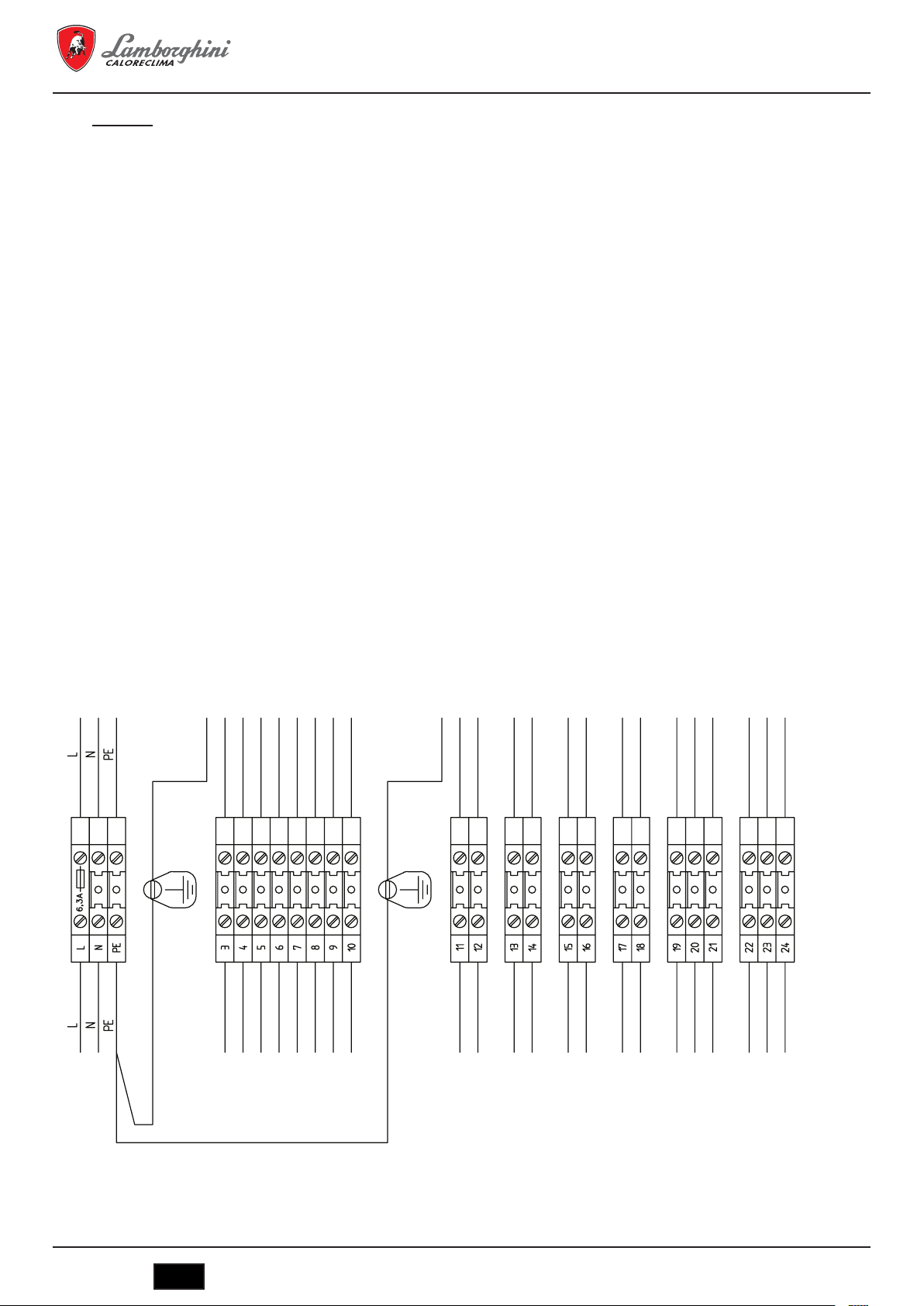
6.1.2 Schema della morsettiera dei collegamenti elettrici
8
Pilota led 1° stadio bruciatore
9
Pilota led 2° stadio bruciatore
10
Pilota led blocco bruciatore
11
Pilota led pressostato di sicurezza
12
Termostato TR1 regolazione 2° stadio
13
Termostato TR1 regolazione 1° stadio
14
Predisposizione per centralina di termoregolazione
(*) Solo pannelli BT
(**) Solo pannelli BT 3 stadi
L
N 14
Alimentazione pannello dei comandi
3
Alimentazione bruciatore
4 17
5
Termostato 1
6 19
Termostato 1
8 21
a
fase
a
fase
9 Pilota di blocco 22
10 Pilota di funzionamento 2° fase 23
11
Alimentazione pompa impianto
12
cod. 3541O220 - Rev. 00 - 03/2018
13
Accensione caldaia a distanza
(se esiste; in caso contrario, ponte)
15
Sicurezza caldaia a distanza
(se esiste; in caso contrario, ponte)
16
Termostato ambiente
18
20
Segnale per pompa anticondensa7
a
Termostato 3
fase
IT
9

6.1.3 Schema elettrico per bruciatore e pompa monofase
Schema elettrico
MEGAPREX N 720N ÷ 1060N
1 - (S1) Autorizzazione accensione a distanza
2 - (TS1) Termostato di sicurezza caldaia
3 - (S2) Autorizzazione esterna di sicurezza
4 - (TR1) Termostato 1
5 - (SA2) Interruttore accensione bruciatore
6 - (N1) Termometro digitale
7 - (B1) Termoresistenza acqua caldaia
8 - (SB1) Pulsante di prova termostato
9 - (TR2) Termostato 2
10 - (TR2) Termostato 3
SOLO PER PANNELLO 3° FIAMMA
11 - (XT1) Contatto gestione pompa anticondensa
SOLO PER PANNELLO BASSA
TEMPERATURA
12 - (S3) Termostato ambiente
13 - (TR3) Termostato
14 - (SA3) Interruttore accensione circolatore
15 - (P1) Pompa di circolazione acqua
16 - (SA1) Interruttore accensione caldaia
17 COLLEGAMENTI BRUCIATORE
17 - (17/a) Blocco bruciatore
17 - (17/b) Seconda fiamma
17 - (17/c) Autorizzazione 1° fiamma
17 - (17/d) Autorizzazione 2° fiamma
17 - (17/e) Alimentazione bruciatore
17 - (17/f) Autorizzazione 3° fiamma
°
fiamma caldaia
°
fiamma caldaia
°
fiamma caldaia
10
IT
cod. 3541O220 - Rev. 00 - 03/2018

MEGAPREX N 720N ÷ 1060N
Schema dei collegamenti
cod. 3541O220 - Rev. 00 - 03/2018
IT
11
Morsettiere
Massima corrente
assorbita 3 Amp
IIIIIIIIIII
MEGAPREX N 720N ÷ 1060N
Massima corrente
assorbita 3 Amp
IIIII
Ponticellare se non esiste
I
III
III
Ponticellare se non esiste
Ponticellare se non esiste
III
SOLO PER PANNELLO BASSA TEMPERATURA
IIIII
IIIII
amma
amma
amma
°
Alimentazione 230 Vca 50-60Hz Monofase (fase)
Alimentazione 230 Vca 50-60Hz Monofase (neutro)
Alimentazione 230 Vca 50-60Hz Monofase (messa a terra)
Alimentazione bruciatore 230 Vca 50-60Hz Monofase (terra)
Alimentazione bruciatore 230 Vca 50-60Hz Monofase (fase)
Alimentazione bruciatore 230 Vca 50-60Hz Monofase (neutro)
Segnale funzionamento bruciatore 1
amma
°
°
°
Segnale funzionamento bruciatore 1
Segnale funzionamento bruciatore 2
Segnale funzionamento bruciatore 2
Segnale blocco bruciatore
Segnale blocco bruciatore
amma bruciatore [ Com ]
amma bruciatore [ NO ]
amma bruciatore [ NC ]
°
°
°
/ 3
/ 3
/ 3
°
°
°
Alimentazione pompa impianto 230 Vca 50-60Hz Monofase (terra)
Alimentazione pompa impianto 230 Vca 50-60Hz Monofase (fase)
Alimentazione pompa impianto 230 Vca 50-60Hz Monofase (neutro)
Segnale accensione caldaia da lontano
Segnale accensione caldaia da lontano
Segnale di sicurezza caldaia esterno
Segnale di sicurezza caldaia esterno
Termostato ambiente
Termostato ambiente
Segnale pompa anticondensa caldaia [ Com ]
Segnale pompa anticondensa caldaia [ NO ]
Segnale pompa anticondensa caldaia [ NC ]
Termostato 2
Termostato 2
Termostato 2
12
IT
cod. 3541O220 - Rev. 00 - 03/2018
MEGAPREX N 720N ÷ 1060N
IT
Temperatura mandata acqua caldaia
Interruttore bruciatore
IT
Interruttore bruciatore
IT
Temperatura mandata acqua caldaia
Strumento stato caldaia/Temperatura acqua
Interruttore bruciatore
Interruttore circolatore
IT
Interruttore bruciatore
IT
Temperatura mandata acqua caldaia
Strumento stato caldaia/Temperatura acqua
Circolatore acqua impianto
Interruttore bruciatore
Interruttore circolatore
Pulsante test
IT
Interruttore bruciatore
Interruttore circolatore
Pulsante test
IT
Temperatura mandata acqua caldaia
Strumento stato caldaia/Temperatura acqua
Circolatore acqua impianto
Consenso accensione remoto
Interruttore bruciatore
Interruttore circolatore
Pulsante test
Termostato 1° stadio bruciatore
IT
Interruttore bruciatore
Interruttore circolatore
Pulsante test
Termostato 1° stadio bruciatore
IT
Temperatura mandata acqua caldaia
Strumento stato caldaia/Temperatura acqua
Circolatore acqua impianto
Consenso accensione remoto
Interruttore bruciatore
Interruttore circolatore
Pulsante test
Termostato 1° stadio bruciatore
IT
Interruttore bruciatore
Interruttore circolatore
Pulsante test
Termostato 1° stadio bruciatore
Termostato 2° stadio bruciatore
Termostato di sicurezza caldaia
IT
Temperatura mandata acqua caldaia
Strumento stato caldaia/Temperatura acqua
Circolatore acqua impianto
Consenso accensione remoto
Consenso di sicurezza esterno
Termostato ambiente
Interruttore accensione caldaia
Interruttore bruciatore
Interruttore circolatore
Pulsante test
Termostato 1° stadio bruciatore
Termostato 2° stadio bruciatore
Termostato di sicurezza caldaia
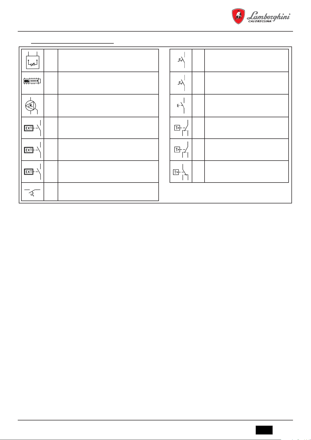
Legenda simboli/componenti schema elettrico
B1
QG2Temperatura scarico acqua
N1
QG2Strumento stato caldaia/Temperatura acqua
P1
QG2Circolatore acqua impianto
S1
QG2Autorizzazione accensione a distanza
S2
QG2Autorizzazione esterna di sicurezza
S3
QG2Termostato ambiente
SA1
QG2Interruttore accensione caldaia
SA2
QG2Interruttore bruciatore
SA3
QG2Interruttore circolatore
SB1
QG2Pulsante di prova
TR1
QG2Termostato 1° fase bruciatore
TR2
QG2Termostato 2° / 3° fase bruciatore
TS1
QG2Termostato di sicurezza caldaia
6.2 Pannello di controllo EBM (Efcient Boiler Management) (Fig. 12)
C16015150 – Pannello di controllo EBM (Efficient Boiler Management)
6.2.1 Pannello (Fig. 12)
Il pannello di controllo EBM non fornito di serie con la caldaia offre, tra le altre, le seguenti funzioni:
- Selezione della lingua di utilizzo
- Selezione delle modalità di funzionamento: riscaldamento, funzionamento economico e programmazione oraria, impostazione vacanze.
- Controllo della pompa della caldaia
- Controllo della pompa di bypass anticondensa
- Controllo del bruciatore a uno stadio
- Controllo del bruciatore a due stadi
- Controllo del bruciatore modulante
- Conteggio ore degli stadi del bruciatore
- Visualizzazione dei parametri della caldaia
- Visualizzazione degli allarmi prodotti
- Funzione climatica (con sonda esterna optional).
È in grado di controllare un impianto con configurazione massima di:
- Una zona a temperatura elevata per il controllo della pompa
- Una zona o due zone a temperatura bassa con valvola miscelatrice e pompa
- Un accumulatore di ACS, controllo pompa per temperatura dell'accumulatore
Altre applicazioni:
Può essere utilizzato per collegamenti a cascata per un totale di max. 16 caldaie, sistema master-slave. Può essere integrato con un impianto
solare.
cod. 3541O220 - Rev. 00 - 03/2018
IT
13

6.2.2 Schemi elettrici
Schema elettrico
MEGAPREX N 720N ÷ 1060N
1 - (2TS1) Termostato di sicurezza caldaia
2 - (2XT1)
3 - (2BU1) COLLEGAMENTI BRUCIATORE
3 - (2BU1) - A Blocco bruciatore
3 - (2BU1) - B Consenso 1° Fiamma
3 - (2BU1) - C Alimentazione Bruciatore MAX. 3A
Segnalazione per apparecchiature esterne
Segnale 230Vac intervento termostato
sicurezza caldaia
14
IT
cod. 3541O220 - Rev. 00 - 03/2018

MEGAPREX N 720N ÷ 1060N
Schema dei collegamenti dell’unità base di controllo (parte 1)
1 - (3P2) Pompa bypass anticondensa caldaia
2 - (3P1) Pompa circolazione acqua
3 - (3B1) Sensore temperatura ritorno acqua caldaia
4 - (3B1) Sensore temperatura ambiente esterno
Max. 2 A
Eventualmente usare come consenso
Max. 2 A
Eventualmente usare come consenso
OPTIONAL
Usare sonda NTC 10K
OPTIONAL
Usare sonda NTC 10K
cod. 3541O220 - Rev. 00 - 03/2018
IT
15

MEGAPREX N 720N ÷ 1060N
Schema dei collegamenti dell’unità base di controllo (parte 2)
1 SAFETY-LOOP
2 - (4B1) Sensore temperatura mandata acqua
3 - (4N1) Pannello unità operatore
Ponticellare se non è presente nessun
altro consenso di sicurezza dell’impianto
caldaia
Usare sonda NTC 10K
AVS 37.294
16
IT
cod. 3541O220 - Rev. 00 - 03/2018

MEGAPREX N 720N ÷ 1060N
Schema dei morsetti per il collegamento del pannello
QG - M
Morsettiera generale
Alimentazione 230 Vca 50-60Hz Monofase (Fase)
Alimentazione 230 Vca 50-60Hz Monofase (Neutro)
Alimentazione 230 Vca 50-60Hz Monofase (Messa a terra)
BM - 2BU1 - Alimentazione bruciatore 230 Vca 50-60Hz Monofase (Terra)
BM - 2BU1 - Alimentazione bruciatore 230 Vca 50-60Hz Monofase (Fase)
BM - 2BU1 - Alimentazione bruciatore 230 Vca 50-60Hz Monofase (Neutro)
BM - 2BU1 - Segnale 1
BM - 2BU1 - Segnale 1
BM - 2BU1 - Segnale di blocco bruciatore
BM - 2XT1 - Segnale 230Vca termostato di sicurezza della caldaia
BM - 2XT1 - Segnale 230Vca termostato di sicurezza della caldaia
Schema dei morsetti di collegamento dell’unità base di controllo
QG
Morsetto RVS63.283
BM - Segnale di sicurezza dell’impianto
BM - Segnale di sicurezza dell’impianto
BM - 3P1 - Pompa dell'acqua della caldaia (230 Vca - Fase)
BM - 3P1 - Pompa dell'acqua della caldaia (230 Vca - Terra)
BM - 3P1 - Pompa dell'acqua della caldaia (230 Vca - Neutro)
BM - 3P2 - Pompa di bypass anticondensa (230 Vca - Fase)
BM - 3P2 - Pompa di bypass anticondensa (230 Vac - Terra)
BM - 3P2 - Pompa di bypass anticondensa (230 Vac - Neutro)
°
amma bruciatore
°
amma bruciatore
I
I
Massima corrente
I
I
assorbita 3 Amp
I
I
I
I
I
I
I
Ponticellare se non è necessario
I
I
I
I
MAX. 2A
I
I
I
I
I
I
MAX. 2A
I
I
I
BM - 4B1 - Sonda temperatura della caldaia
BM - 4B1 - Sonda temperatura della caldaia
BM - 3B3 - Sonda esterna
BM - 3B3 - Sonda esterna
I
I
I
BM - 3B1 - Sonda temperatura di ritorno della caldaia
BM - 3B1 - Sonda temperatura di ritorno della caldaia
cod. 3541O220 - Rev. 00 - 03/2018
OPTIONAL
IT
17

Legenda simboli/componenti schema elettrico
MEGAPREX N 720N ÷ 1060N
2BU1
BM2Bruciatore caldaia
2HL1
QG2Lampada alimentazione 230Vca pannello
2HL2
Lampada allarme intervento termostato di
QG
sicurezza.
2
2SB1
QG2Interruttore generale accensione caldaia
2SB2
QG2Interruttore accensione bruciatore
2TS1
QG2Termostato di sicurezza caldaia
2XT1
Segnale 230Vca intervento termostato di
BM
sicurezza
2
3B1
BM3Sonda temperatura ritorno caldaia
3B3
BM3Sonda esterna
3N1
Unità a base del comando MASTER
QG
(RSV 63 283/109)
3
3P1
BM3Pompa impianto
3P2
BM3Pompa di bypass anticondensa
4B1
BM4Sensore temperatura acqua di andata caldaia
4N1
QG4Interfaccia utente Siemens AVS37.294
6.3 Nota sui collegamenti
Il cavo di alimentazione del pannello di tipo FG7 RN-F 3G1,5 di serie è già collegato alla scatola dei collegamenti. In caso di sostituzione, utilizzare un cavo adeguato in base alle normative vigenti. L’alimentazione del bruciatore arriva direttamente dalla scatola dei collegamenti, se si
tratta del tipo monofase e con intensità massima di 3 A. L’alimentazione del circolatore dell'acqua dell’impianto viene direttamente dalla scatola
dei collegamenti, se si tratta del tipo monofase e con intensità massima di 3 A. Se il bruciatore o la pompa hanno una maggiore intensità rispetto
a quanto previsto o se si tratta di alimentazione trifase, sarà necessario utilizzare relè di potenza collegati all’interfaccia, alle uscite previste
nella scatola dei collegamenti.
L’autorizzazione di accensione a distanza permette di accendere la caldaia da lontano. In caso di mancato utilizzo, ponticellare. L’autorizzazione per la sicurezza esterna della caldaia permette di inserire un contatto posteriore che provoca lo spegnimento del bruciatore. In caso di mancato utilizzo, ponticellare. Il contatto per il termostato ambiente agisce solo sul circolatore dell'acqua. In caso di mancato utilizzo, ponticellare.
7. MESSA IN FUNZIONE
7.1 Controlli preliminari
Realizzati gli allacci idraulici, elettrici e del combustibile alla caldaia, prima della messa in funzione è necessario verificare che:
- Il vaso di espansione e la valvola di sicurezza siano correttamente collegati e non siano in alcun modo intercettabili.
- I bulbi dei termostati di regolazione, di sicurezza della temperatura minima e del termometro siano introdotti nelle rispettive guaine.
- Le turboeliche siano situate in tutti i tubi dei fumi.
- L’impianto sia pieno d’acqua e l'aria sia totalmente assente.
- La pompa o le pompe funzionino correttamente.
- Gli allacci idraulici, elettrici e di sicurezza necessari e del combustibile siano stati realizzati in conformità alle disposizioni nazionali e locali
in vigore.
- Il bruciatore sia stato montato in conformità alle istruzioni riportate nel manuale del fabbricante.
- La tensione e la frequenza di rete siano compatibili con il bruciatore e il sistema elettrico della caldaia.
- L’impianto sia in grado di assorbire la quantità di calore che verrà prodotta.
- La pompa di ricircolo sia installata come descritto nel paragrafo 5.5.5.
18
IT
cod. 3541O220 - Rev. 00 - 03/2018

MEGAPREX N 720N ÷ 1060N
7.2 Prima accensione
Dopo gli esiti positivi dalle verifiche indicate nel paragrafo anteriore, si potrà procedere alla prima accensione del bruciatore, che dovrà essere
effettuata da un tecnico in servizio e riconosciuto dall’azienda fabbricante del bruciatore. Il tecnico assumerà tutta la responsabilità relativa al
campo di regolazione all’interno del campo di potenza dichiarato e omologato della caldaia. Dopo aver aperto i rubinetti di blocco del combustibile e controllato che non vi siano perdite nella rete di fornitura, impostare tutti gli interruttori in posizione ON (collegato). In questo modo, il
bruciatore è pronto per la prima accensione e per la regolazione che compete unicamente al tecnico autorizzato.
Durante la prima accensione, sarà necessario verificare che lo sportello, la flangia del bruciatore e i collegamenti con la canna fumaria siano a
tenuta stagna e che la base della canna fumaria presenti una leggera pressione negativa. La portata del combustibile dovrà corrispondere ai
dati della targhetta della caldaia e, in nessun caso, dovrà essere superiore al valore massimo della potenza nominale dichiarata. La temperatura
dei fumi non dovrà mai essere inferire a 160°C.
7.3 Spegnimento della caldaia
- Regolare il termostato d’esercizio al minimo.
- Eliminare la tensione dal bruciatore e chiudere l'alimentazione del combustibile.
- Lasciar funzionare le pompe fino a quando non vengono chiuse dal termostato di temperatura minima.
- Eliminare la tensione dal quadro elettrico.
8. MANUTENZIONE
8.1 Norme generali
La manutenzione periodica è essenziale per la sicurezza, il rendimento e la durata dell'apparecchio.
Tutte le operazioni devono essere effettuate dal personale qualificato. Ogni operazione di pulizia e manutenzione dovrà essere preceduta dalla
chiusura dell’alimentazione del combustibile, una volta rimossa la tensione elettrica.
Per ottenere un buon funzionamento e il massimo rendimento della caldaia, è necessaria la pulizia regolare della camera di combustione, dei
tubi dei fumi e della camera dei fumi.
8.2 Manutenzione ordinaria
La manutenzione deve essere stabilita in base al combustibile usato, al numero di accensioni, alle caratteristiche dell’impianto ecc.; di conseguenza, non è possibile stabilire a priori un intervallo di tempo tra una manutenzione e la successiva.
In linea di principio, si consigliano i seguenti intervalli di pulizia in base al combustibile:
- Caldaie a gas: una volta all'anno
- Caldaie a gasolio: due volte all’anno
In tutti i casi, sarà necessario rispettare le eventuali norme locali riguardanti la manutenzione.
Durante le operazioni di manutenzione ordinaria, dopo aver rimosso le turboeliche, sarà necessario pulire con uno scopettone il fascio tubiero
e il focolare. Rimuovere i depositi accumulati nella camera dei fumi tramite l’apertura degli sportelli d’ispezione. In caso di azioni più energiche,
rimuovere la camera dei fumi posteriori e, se deteriorata, sostituire la guarnizione di tenuta stagna dei fumi. Verificare che lo scarico dell'acqua
di condensa non sia ostruito. Sarà necessario comprovare il buon funzionamento degli organi di controllo e di misurazione del generatore.
In questa occasione, sarà necessario registrare la quantità di acqua di rifornimento utilizzata, dopo aver effettuato le opportune analisi sull'acqua; effettuare quindi una disincrostazione preventiva.
I sali di calcio e di magnesio disciolti nell'acqua ordinaria, con ripetuti rabbocchi, danno origine a depositi nella caldaia e provocano il surriscaldamento delle lamiere, con la possibilità che si producano danni non attribuibili né ai materiali né alla tecnica di fabbricazione e, pertanto, non
coperti dalla garanzia. Dopo aver effettuato le operazioni di manutenzione e pulizia e la successiva accensione, verificare la tenuta stagna
dello sportello e della camera dei fumi; in caso di perdite del prodotti di combustione, sostituire la guarnizione di tenuta stagna corrispondente.
Le operazioni realizzate verranno annotate nel registro generale.
8.3 Manutenzione straordinaria
Manutenzione straordinaria di fine stagione o per lunghi periodi di inattività.
Devono essere realizzate tutte le operazioni descritte nel capitolo precedente; inoltre:
- Controllare lo stato di usura delle turboeliche.
- Dopo aver pulito il circuito dei fumi, è utile passare un panno imbevuto di soluzione disciolta nella soda caustica. Dopo aver lasciato asciugare, ripassare tutte le superfici con un panno imbevuto nell’olio.
- Si raccomanda di collocare all’interno del focolare sostanze igroscopiche (ossido di calcio, gel di silice in piccoli contenitori) e chiudere ermeticamente in modo tale che non entri l'aria.
- Non svuotare l’impianto né la caldaia.
- Proteggere con una miscela di olio e grafite le viti, i dadi e i perni dello sportello.
Le operazioni realizzate verranno annotate nel registro della manutenzione.
cod. 3541O220 - Rev. 00 - 03/2018
IT
19

MEGAPREX N 720N ÷ 1060N
8.4 Pulizia della caldaia (Fig. 13)
Per effettuare la pulizia, procedere nel modo seguente:
- La caldaia ha in dotazione una spazzola per la pulizia dei tubi dei fumi.
- Aprire lo sportello anteriore (1) ed estrarre le turboeliche (2).
- Pulire le superfici interne della camera di combustione e del passaggio dei fumi utilizzando uno scopettone (3) o un altro utensile adeguato
per tale scopo.
- Rimuovere i depositi accumulati nella camera dei fumi tramite l’apertura dei coperchi per la pulizia (4). In caso di azioni più energiche, rimuovere la camera dei fumi (5), sostituendo la guarnizione di tenuta stagna prima di effettuare il montaggio.
- Verificare periodicamente che lo scarico dell'acqua di condensa (6) non sia ostruito.
8.5 Verica del funzionamento della caldaia
Prima di effettuare l'accensione e la prova funzionale della caldaia, verificare che:
- le turboeliche siano situate nei tubi di scambio.
- I rubinetti del circuito idraulico e quelli del combustibile siano aperti.
- Vi sia combustibile disponibile.
- Il vaso di espansione sia caricato adeguatamente.
- La pressione a freddo del circuito idraulico sia superiore a 1 bar e inferiore al limite massimo previsto dalla caldaia.
- I circuiti idraulici non contengano aria.
- Siano stati realizzati gli allacci elettrici alla rete di alimentazione e ai componenti (bruciatore, pompa, quadro dei comandi, termostati ecc.).
- È obbligatorio rispettare il collegamento fase-neutro; il collegamento a terra è obbligatorio.
Una volta realizzate le operazioni precedentemente descritte, per mettere in funzione la caldaia è necessario:
- Se l’impianto è provvisto di termoregolatore o di cronotermostato/i, verificare che sia/no in stato “attivo".
- Regolare il/i cronotermostato/i ambiente o la termoregolazione alla temperatura desiderata.
- Collocare l’interruttore generale dell’impianto in posizione “acceso”.
- Regolare il termostato della caldaia situato nel quadro dei comandi.
- Collocare l’interruttore principale del quadro dei comandi su “ON” e verificare l'accensione del segnale verde.
La caldaia realizzerà la fase di accensione e rimarrà in funzionamento fino a quando non vengano raggiunte le temperature regolate. In caso di
anomalie di accensione o di funzionamento, la caldaia andrà in “BLOCCO”, segnalato dal pilota rosso situato sul bruciatore e dal segnale rosso
sul quadro dei comandi. Dopo un “BLOCCO”, attendere circa 30 secondi prima di ripristinare le condizioni di messa in funzione; per ripristinare
le condizioni di messa in funzione, premere il “pulsante/pilota” del bruciatore e attendere che si accenda la fiamma. In caso di mancato funzionamento, è possibile ripetere questa operazione 2 o 3 volte al massimo; in seguito, verificare:
- Quanto riportato nel manuale d’istruzioni del bruciatore.
- Il capitolo “VERIFICA DEL FUNZIONAMENTO DELLA CALDAIA”.
- Gli allacci elettrici previsti nello schema che si trova accanto al quadro dei comandi. Dopo aver effettuato la messa in funzione, è necessario
verificare che l'apparecchio si arresta e che successivamente venga nuovamente messo in funzione:
- Modificando la regolazione del termostato della caldaia.
- Intervenendo sull’interruttore principale del quadro dei comandi.
- Intervenendo sul termostato ambiente o sul programmatore orario o sulla termoregolazione.
- Verificando la libera e corretta rotazione delle pompe.
- Verificando l'arresto totale della caldaia, agendo sull'interruttore generale dell’impianto.
Se sono state rispettate tutte le condizioni, rimettere in funzione l'apparecchio, effettuare il controllo della combustione (analisi dei fumi), della
portata del combustibile e della tenuta stagna della guarnizione dello sportello e della camera dei fumi.
8.6 Verica del funzionamento del bruciatore
- Consultare il manuale d’istruzioni del bruciatore.
- Attenersi a tutte le norme locali in materia di manutenzione del bruciatore.
20
IT
cod. 3541O220 - Rev. 00 - 03/2018

MEGAPREX N 720N ÷ 1060N
8.7 Possibili anomalie e soluzioni
Di seguito, viene riportato un elenco con le indicazioni delle principali anomalie e avarie che possono verificarsi nella gestione della caldaia,
specificandone le possibili cause e soluzioni
ANOMALIE
IL GENERATORE SI SPORCA FACILMENTE
CAUSA: Bruciatore regolato in modo non corretto SOLUZIONE: Controllare la regolazione del bruciatore (analisi dei fumi)
Canna fumaria ostruita Pulire il percorso dei fumi e la canna fumaria
Percorso dell'aria del bruciatore sporco Pulire il percorso dell'aria del bruciatore
IL GENERATORE NON RIESCE AD AUMENTARE LA TEMPERATURA
CAUSA: Corpo del generatore sporco SOLUZIONE: Pulire il percorso dei fumi
Unione generatore/bruciatore Controllare i dati e le regolazioni
Portata bruciatore insufficiente Controllare la regolazione del bruciatore
Termostato di regolazione Verificare il corretto funzionamento
Verificare la temperatura programmata
IL GENERATORE ENTRA IN BLOCCO DI SICUREZZA TERMICA CON SEGNALE LUMINOSO NEL QUADRO DEI COMANDI
CAUSA: Termostato di regolazione SOLUZIONE: Verificare il corretto funzionamento
Verificare la temperatura programmata
Verificare il cablaggio elettrico
Verificare i bulbi delle sonde
Mancanza di acqua Verificare la pressione del circuito
Presenza dell'aria Verificare la valvola di spurgo
IL GENERATORE ACQUISISCE LA TEMPERATURA MA L’IMPIANTO DI RISCALDAMENTO È FREDDO
CAUSA: Presenza dell'aria nell’impianto SOLUZIONE: Spurgare l’impianto
Pompa in avaria Sbloccare la pompa
Termostato di temp. minima (se presente) Verificare la temperatura programmata
ODORI DI PRODOTTI NON BRUCIATI
CAUSA: Dispersione dei fumi in ambiente SOLUZIONE: Verificare la pulizia del corpo del generatore
Verificare la pulizia del condotto dei fumi
Verificare l'ermeticità del generatore, dei condotti dei fumi e della canna fumaria
INTERVENTI FREQUENTI DELLA VALVOLA DI SICUREZZA
CAUSA: Pressione del circuito dell’impianto SOLUZIONE: Verificare la pressione di carico
Verificare il circuito dell’impianto
Verificare la regolazione
Verificare la temperatura programmata
Vaso di espansione dell’impianto Verificare
cod. 3541O220 - Rev. 00 - 03/2018
IT
21

MEGAPREX N 720N ÷ 1060N
1. PRESENTACIÓN ........................................................................................................................................................................ 23
2. ADVERTENCIAS GENERALES ................................................................................................................................................ 23
3. CERTIFICACIÓN ........................................................................................................................................................................ 23
4. CARACTERÍSTICAS TÉCNICAS, DE FABRICACIÓN Y MEDIDAS ......................................................................................... 23
4.1 Descripción del aparato ............................................................................................................................................................................... 23
4.2 Principio de funcionamiento ......................................................................................................................................................................... 24
4.3 Datos técnicos - Medidas - Conexiones hidráulicas .................................................................................................................................... 24
4.4 Identicación ................................................................................................................................................................................................ 25
5. INSTALACIÓN ............................................................................................................................................................................ 25
5.1 Embalaje ...................................................................................................................................................................................................... 25
5.2 Manipulación ................................................................................................................................................................................................ 25
5.3 Local de instalación (Fig. 4) ......................................................................................................................................................................... 25
5.4 Evacuación de los productos de combustión (Fig. 5) .................................................................................................................................. 26
5.5 Conexiones hidráulicas ................................................................................................................................................................................ 26
5.5.1 Agua de alimentación ............................................................................................................................................................................. 26
5.5.2 Tuberías de ida/retorno instalación ........................................................................................................................................................ 26
5.5.3 Tuberías de llenado/vaciado instalación ................................................................................................................................................ 26
5.5.4 Tuberías vaso de expansión y válvula de seguridad ............................................................................................................................. 27
5.5.5 Bomba de recirculación (Fig. 6) ............................................................................................................................................................. 27
5.6 Regulación de la puerta (Fig. 7) .................................................................................................................................................................. 27
5.7 Montaje del quemador (Fig. 8) ..................................................................................................................................................................... 27
5.8 Conexión tubo de enfriamiento a la mirilla (Fig. 9) ...................................................................................................................................... 28
5.9 Montaje del revestimiento de paneles mod. 720÷1060. Secuencia (Fig. 10) .............................................................................................. 28
6. PANEL DE CONTROL (OPCIONAL) ......................................................................................................................................... 28
6.1 Panel de control termostático BT 2 y 3 Etapas de quemador (Fig. 11) ....................................................................................................... 28
6.1.1 Vista frontal del panel (Fig. 11)............................................................................................................................................................... 29
6.1.2 Esquema de la regleta de conexiones eléctricas ................................................................................................................................... 29
6.1.3 Esquema eléctrico para quemador y bomba monofásica ...................................................................................................................... 30
6.2 Panel de control EBM (Efcient Boiler Management) (Fig. 12) ................................................................................................................... 33
6.2.1 Panel (Fig. 12) ........................................................................................................................................................................................ 33
6.2.2 Esquemas eléctricos .............................................................................................................................................................................. 34
6.3 Notas sobre las conexiones ......................................................................................................................................................................... 38
7. PUESTA EN MARCHA ............................................................................................................................................................... 38
7.1 Controles preliminares ................................................................................................................................................................................. 38
7.2 Primer encendido ......................................................................................................................................................................................... 39
7.3 Apagado de la caldera ................................................................................................................................................................................. 39
8. MANTENIMIENTO ...................................................................................................................................................................... 39
8.1 Normas generales ....................................................................................................................................................................................... 39
8.2 Mantenimiento ordinario .............................................................................................................................................................................. 39
8.3 Mantenimiento extraordinario ...................................................................................................................................................................... 39
8.4 Limpieza de la caldera (Fig. 13) .................................................................................................................................................................. 40
8.5 Vericación del funcionamiento de la caldera .............................................................................................................................................. 40
8.6 Vericación del funcionamiento del quemador ............................................................................................................................................ 40
8.7 Posibles averías y soluciones ...................................................................................................................................................................... 41
22
IT
cod. 3541O220 - Rev. 00 - 03/2018
MEGAPREX N 720N ÷ 1060N
1. PRESENTACIÓN
Estimado cliente, Le damos las gracias por haber elegido una caldera MEGAPREX N. Este manual se ha elaborado para informarle,
con advertencias y consejos, sobre la instalación, uso correcto y mantenimiento de la caldera.
Le rogamos que lo lea atentamente y lo guarde para consultas posteriores. Por su propio interés le invitamos a seguir y observar atentamente
las instrucciones que se dan en el presente manual para poder disfrutar plenamente de este producto de alta calidad.
El incumplimiento y la no observación de cuanto figura en el presente manual exoneran a la empresa fabricante de cualquier responsabilidad
e invalidan la garantía.
2. ADVERTENCIAS GENERALES
El manual de instrucciones forma parte del producto y proporciona una descripción de todo aquello que se debe observar en la fase de instalación, uso y mantenimiento.
- Este aparato debe destinarse sólo al uso para el que ha sido expresamente previsto.
- Este aparato sirve para calentar agua a una temperatura inferior a la de ebullición a la presión atmosférica y debe unirse a una in-
stalación de calefacción y/o a una instalación de distribución de agua caliente para uso sanitario, de acuerdo con sus características y prestaciones y a la potencia calorífica.
- Antes de la instalación debe comprobarse que la caldera no haya sufrido ningún daño derivado de la manipulación y el transporte.
- La instalación debe ser realizada por personal debidamente cualificado y de acuerdo con las normas vigentes.
- Antes de realizar cualquier operación de limpieza o de mantenimiento, desenchufe el aparato de la red de suministro eléctrico.
- LAMBORGHINI no responde de los daños ocasionados a personas y/o a cosas debidos a errores en la instalación, de regulación, de mantenimiento y a usos incorrectos.
- La puesta en marcha de la caldera y de la correspondiente instalación debe ser realizada por una persona autorizada.
- La primera puesta en marcha tiene por objetivo verificar el buen funcionamiento de todos los dispositivos de regulación y de control.
- La no utilización del aparato durante un largo período de tiempo requiere la intervención de personal cualificado.
Normativas
El instalador debe respetar la reglamentación local y vigente en cuanto corresponde a: la elección del lugar de instalación de la caldera, el
respeto de las condiciones de ventilación necesarias, que la conexión y la chimenea se encuentren en perfectas condiciones, las conexiones
del combustible, de las instalaciones eléctricas y otras disposiciones eventuales por cuanto respecta a la seguridad.
Condiciones de garantía
La validez de la garantía está subordinada a la observación de las normas y consejos de uso contenidos en el presente manual. Cualquier
incumplimiento o modificación la hará nula. La garantía no cubre los daños ocasionados por la corrosión de condensado ácido de los productos
de la combustión o debidos a la formación de incrustaciones causadas por el uso de aguas duras o agresivas, ya que sólo son imputables a
la explotación de la instalación.
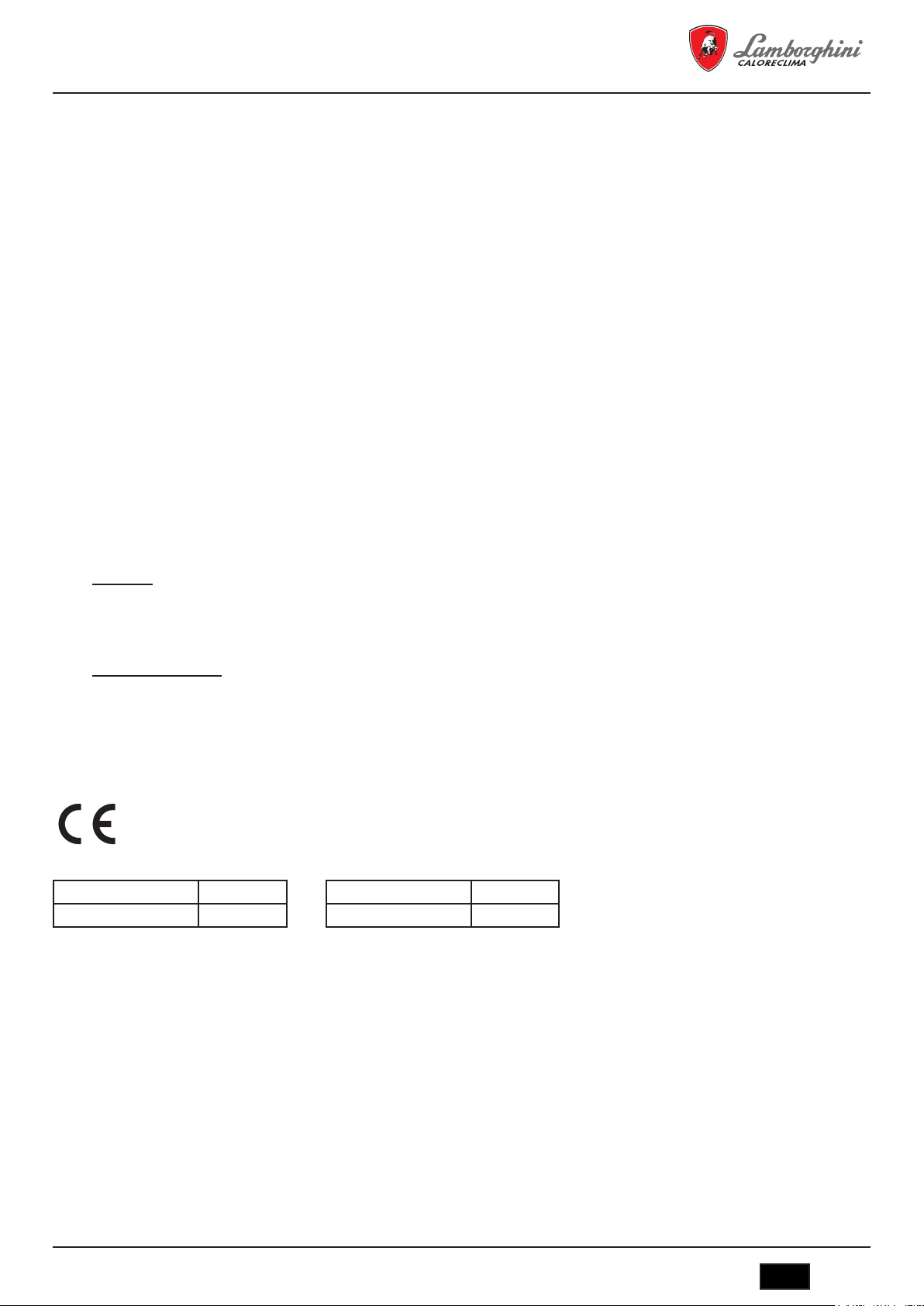
3. CERTIFICACIÓN
El marcado CE acredita que los productos cumplen los requisitos fundamentales de las directivas aplicables.
La declaración de conformidad puede solicitarse al fabricante.
CÓDIGOS DE IDENTIFICACIÓN DE LOS PRODUCTOS
MEGAPREX N 720N 0QIJHBXD
MEGAPREX N 820N 0QIJIBXD
PAÍSES DE DESTINO: IT - ES - RU
MEGAPREX N 940N 0QIJJBXD
MEGAPREX N 1060N 0QIJKBXD
4. CARACTERÍSTICAS TÉCNICAS, DE FABRICACIÓN Y MEDIDAS
4.1 Descripción del aparato
El tipo de construcción de las calderas de la serie MEGAPREX N garantiza potencia y elevados rendimientos con bajas temperaturas de humos, obteniéndose así escasas emisiones contaminantes. La fabricación sigue la norma EN 303 parte 1. Los principales elementos técnicos
del diseño son:
- el cuidadoso estudio de las geometrías, para obtener una relación óptima entre los volúmenes de combustión y las superficies de intercambio
- la elección de los materiales usados, para una larga duración de la caldera.
Las calderas son de combustión presurizada, con 2 pasos de humos, de tipo cilíndrico horizontal con inversión de llama en el hogar, completamente rodeado por el agua que lo enfría, la llama producida por el quemador se invierte periféricamente hacia la parte anterior, donde
los humos entran en el haz tubular en los que se insertan los turbohélices que crean turbulencias que aumentan el intercambio térmico por
convección. A la salida del haz tubular los humos se recogen en la cámara posterior y se encauzan hacia la chimenea.
Las calderas están equipadas con una puerta con bisagra para su apertura hacia la derecha o hacia la izquierda y regulable en altura y profundidad. El cuerpo está aislado mediante un grueso colchón de lana de vidrio recubierto con una capa posterior de material antiroturas. El
acabado externo está formado por paneles de acero barnizado.
cod. 3541O220 - Rev. 00 - 03/2018
IT
23
MEGAPREX N 720N ÷ 1060N
Las calderas están provistas de 2 conexiones de 1/2” para vainas porta bulbos (aptas para alojar 3 bulbos cada una). El panel de mando que
ya está precableado se situara sobre la caldera y permite el funcionamiento automático de la misma.
4.2 Principio de funcionamiento
Las calderas MEGAPREX N están provistas de un hogar cilíndrico ciego, en la que la llama del quemador se invierte periféricamente
hacia delante y desde donde los gases de la combustión entran en los tubos de humos. A la salida, estos se recogen en la cámara de humos
y de ahí se envían a la chimenea. Durante el funcionamiento del quemador la cámara de combustión siempre está a presión. Para conocer el
valor de esta presión vea la Tabla 1, en la columna Pérdidas de carga lado humos. El conducto de humos y la conexión a la chimenea deben
realizarse de acuerdo con las Normas y la Legislación vigente, con conductos rígidos, resistentes a la temperatura, al agua de condensación,
los esfuerzos mecánicos y la estanquidad. (Fig. 1)
4.3 Datos técnicos - Medidas - Conexiones hidráulicas
MEGAPREX N 720N 820N 940N 1060N
Potencia nominal
Potencia de la camara de combustion
Rendimiento útil al 100% Potencia máxima % 92,71 93,10 92,95 93,05
Rendimiento útil al 30% Potencia máxima % 93,60 94,40 94,20 96,75
Capacidad total de la cadera Litros 735 735 850 1250
Perdidas de carga lado de agua
Perdidas de carga lado de humos mbar 4,5 5,6 5,4 6
Presión máxima de ejercicio bar 6 6 6 6
Peso en seco kg 1250 1250 1420 1580
MEDIDAS
ENTRADA AGUA CALIENTE T1 DN 100 DN 100 DN 100 DN 125
RETORNO AGUA CALIENTE T2 DN 100 DN 100 DN 100 DN 125
CONEXIÓN TANQUE DE EXPANSIÓN T3 2 1/2" 2 1/2" 2 1/2" 3"
DESCARGA CALDERA T4 1" 1" 1" 1"
SALIDA DE HUMOS T5 Øe mm 340 340 340 400
min kW 468 533 611 667
max kW 720 820 940 1000
min kW 502 566 651 717
max kW 777 881 1011 1075
mbar 32 40 51 65
mbar 18 25 25 33
mbar 10 18 16 20
A mm 1250 1250 1250 1430
B mm 1784 1784 2024 2028
C mm 1335 1335 1335 1515
D mm 162 162 162 162
E mm 212 212 212 240
F mm 219 219 219 214
G mm 830 830 830 900
H mm 565 565 565 670
I mm 2215 2215 2455 2482
L mm 196 196 196 196
L1 mm 227 227 227 227
M mm 1400 1400 1400 1580
N mm 223 223 223 227
O mm 440 440 480 480
P mm 700 700 900 900
Q mm 1200 1200 1200 1380
R mm 1752 1752 1992 1992
24
IT
cod. 3541O220 - Rev. 00 - 03/2018

MEGAPREX N 720N ÷ 1060N
Leyenda (Fig. 2)
1 Cuadro de mandos T2 Retorno calefacción
2 Placa portaquemador T3 Conexión vaso de expansión
3 Puerta de limpieza de la cámara de humos T4 Vaciado caldera
4 Mirilla control llama T5 Salida de humos
T1 Ida calefacción T6 Conexión quemador
4.4 Identicación
La caldera se puede identificar mediante (Fig. 3):
- Sobre portadocumentos
Está en el interior del hogar de la caldera junto al panel porta instrumentos:
- Manual técnico
- Certificado de garantía
- Placa de características
En la placa de características figuran los datos técnicos y las prestaciones del aparato.
Está pegada en el lateral exterior del panel portainstrumentos.
La alteración, retirada, falta de placas de identificación o todo aquello que no permita la identificación segura del producto, dificulta las operaciones de instalación y mantenimiento.
5. INSTALACIÓN
5.1 Embalaje
Las calderas MEGAPREX N se entregan con: puerta, cámara de humos e aislamiento instalados, mientras que los paneles se hallan
en un embalaje de cartón aparte.
El panel de instrumentos y el colchón de fibra cerámica para la tobera del quemador se hallan dentro de la cámara de combustión.
El panel de instrumento se entrega en una caja de cartón situada en la cámara de combustión.
5.2 Manipulación
Las calderas MEGAPREX N están provistas de ganchos de elevación. Realizar la manipulación con precaución mediante instrumentos
adecuados para su peso. Antes de conectar la caldera retire la base de madera.
5.3 Local de instalación (Fig. 4)
Las calderas MEGAPREX N se instalarán en locales para su uso exclusivo, que respondan a las Normas técnicas y a la Legislación
vigente y provistos de aperturas de ventilación de medidas adecuadas. La aperturas de ventilación deberán ser permanentes, comunicando
directamente con el exterior y situadas a nivel alto y bajo de acuerdo con las normativas vigentes. La ubicación de las aperturas de ventilación,
los circuitos de suministro del combustible, de distribución de la energía eléctrica y de iluminación deberán respetar las disposiciones legales
vigentes en relación con el tipo de combustible empleado. Para facilitar la limpieza del circuito de humos, en la parte anterior de la caldera,
deberá dejarse un espacio libre igual o mayor que la longitud del cuerpo de la caldera y, en ningún caso inferior a 1.300 mm y deberá verificarse que con la puerta abierta a 90º la distancia entre la puerta y la pared adyacente (X), sea como mínimo igual a la longitud del quemador.
El plano de apoyo de la caldera deberá ser totalmente horizontal. Se recomienda prever un zócalo de cemento, llano, capaz de soportar el
peso total de la caldera más el contenido de agua. Para las medidas del zócalo, véase las cotas R x Q (tabla de medidas). En caso de que el
quemador sea alimentado con gas combustible de peso específico superior al del aire, las partes eléctricas deberán situarse a una distancia
del suelo superior a los 500 mm. Estas calderas no se pueden instalar al aire libre porque no está diseñado para funcionar en el exterior y no
dispone de sistemas antihielo automáticos.
COLOCACIÓN EN INSTALACIONES ANTIGUAS
Cuando se coloque la caldera en instalaciones antiguas, verifique que:
- La chimenea sea adecuada para las temperaturas de los productos de la combustión, que esté calculada y construida de acuerdo con la
normativa vigente, que sea estanca, aislada y que no haya obstrucciones o estrechamientos.
- La instalación eléctrica se haya realizado de acuerdo con las Normas vigentes y por personal cualificado.
- La línea de suministro del combustible y el eventual depósito se hayan realizado de acuerdo con las normas vigentes.
- El/los vaso/s de expansión aseguran la total absorción de la dilatación del fluido contenido en la instalación.
- El caudal, la presión estática y la dirección del flujo de las bombas de circulación sean adecuados.
- La instalación esté limpia de fangos, incrustaciones, eliminado el aire y que se haya verificado la estanquidad.
- Se haya previsto un sistema de tratamiento del agua de alimentación/reabastecimiento (véase valores de referencia).
cod. 3541O220 - Rev. 00 - 03/2018
IT
25

MEGAPREX N 720N ÷ 1060N
5.4 Evacuación de los productos de combustión (Fig. 5)
El conducto de humos y la conexión a la chimenea deben realizarse de acuerdo con las Normas y la Legislación vigente, con conductos rígidos,
resistentes a la temperatura, al agua de condensación, los esfuerzos mecánicos y la estanquidad.
La chimenea debe asegurar la presión negativa mínima prevista por las normas vigentes, considerando como presión “cero” en la conexión con
el conducto de humos. La chimenea y los conductos de humos inadecuados o mal dimensionados pueden ampliar el ruido de la combustión,
generar problemas de condensación e influir negativamente en los parámetros de combustión. Los conductos de evacuación no aislados son
una fuente de peligros. La estanquidad de las uniones se realizará con materiales resistentes a temperaturas de cómo mínimo 250ºC. En el
tramo de unión entre la caldera y la chimenea, se tienen que prever puntos adecuados de medición de la temperatura de los humos y el análisis
de los productos de la combustión.
En cuanto a la sección y la altura de la chimenea, debe hacerse referencia a las reglamentaciones nacionales y locales en vigor.
5.5 Conexiones hidráulicas
5.5.1 Agua de alimentación
Las características químicas del agua de la instalación y de reabastecimiento, son fundamentales para el buen funcionamiento y la seguridad
de la caldera; se aplicarán al agua los oportunos sistemas de tratamiento. Como valores de referencia se pueden considerar los que figuran
en la tabla.
DUREZA TOTAL ppm 10
ALCALINIDAD mg/l CaCO3 750
PH 8÷9
SÍLICE ppm 100
CLORUROS ppm 3500
Es absolutamente indispensable el tratamiento del agua usada para la instalación de calefacción en los siguientes casos:
- Instalaciones muy extensas
- Agua muy dura
- Frecuentes introducciones de agua de reabastecimiento en la instalación
En caso de que fuera necesario el vaciado parcial o total de la instalación, se recomienda realizar el sucesivo llenado con agua tratada. Para el
control del volumen de los reabastecimientos, se aconseja instalar un contador sobre la tubería. Los fenómenos más comunes que se producen
en las instalaciones térmicas son:
- Incrustaciones de cal
La cal se concentra en los puntos donde la temperatura de la pared es mayor. Las incrustaciones de cal, debido a su baja conductividad térmica, reducen el intercambio térmico incluso en caso de la presencia de pocos milímetros, impiden el intercambio térmico entre los humos y el
agua, comportando un aumento de la temperatura de las partes expuestas a la llama y las consiguientes fisuras en la placa tubular.
- Corrosión lado agua
La corrosión de las superficies metálicas de la caldera, lado agua, se debe al paso del hierro a solución mediante sus iones. En este proceso
tiene gran importancia la presencia de gases disueltos y en particular del oxígeno y del anhídrido carbónico. En presencia de aguas ablandadas
y/o desmineralizadas, se estará libre del fenómeno de incrustación, pero no sucede lo mismo con las corrosiones. En este caso es necesario
acondicionar el agua con inhibidores de los procesos corrosivos.
5.5.2 Tuberías de ida/retorno instalación
Las medidas de las tuberías de ida y retorno están indicadas para cada modelo de caldera en la tabla MEDIDAS. Asegúrese en la instalación
que haya un número suficiente de purgadores.
Las conexiones de la caldera no deben soportar el peso de las tuberías de unión a la instalación, por lo tanto deberá instalar los soportes
adecuados.
5.5.3 Tuberías de llenado/vaciado instalación
Para el llenado y el vaciado de la caldera se puede conectar un grifo a la conexión T4 que está en la parte posterior (véase diseño MEDIDAS
Fig. 2).
26
IT
cod. 3541O220 - Rev. 00 - 03/2018

MEGAPREX N 720N ÷ 1060N
5.5.4 Tuberías vaso de expansión y válvula de seguridad
Las calderas MEGAPREX N son aptas para funcionar con circulación de agua forzada con vaso de expansión tanto abierto como cerrado. Un vaso de expansión siempre es necesario, para compensar el aumento de volumen del agua debido al calentamiento. En el primer caso,
la altura de la columna hidrostática deberá ser igual al menos a 3 metros por encima del cuerpo de la caldera y deberá tener una capacidad tal
que contenga, entre la superficie libre del agua en el vaso y el tubo del rebosadero, el aumento del volumen de toda el agua de la instalación.
Son preferibles vasos altos y estrechos de modo que se exponga al contacto con el aire la menor superficie de agua posible, reduciéndose así
la evaporación. En el segundo caso, la capacidad del vaso de expansión cerrado se debe calcular teniendo en cuenta:
- el volumen total del agua contenida en la instalación
- la presión máxima de ejercicio de la instalación
- la presión máxima de ejercicio del vaso de expansión
- la presión de precarga inicial del vaso de expansión
- la temperatura máxima de ejercicio de la caldera (la temperatura máxima del termostato montado sobre el panel es de 90ºC. para realizar
este cálculo se recomienda considerar 100ºC).
La tubería de expansión une el vaso de expansión con la instalación. Esta tubería que partirá de la conexión T3 (véase tabla Medidas) no
deberá tener ninguna válvula de corte. Instale en la conexión T3 o en la tubería de descarga a 0,5 m de la brida de partida, una válvula de
seguridad adecuada para la capacidad de la caldera que cumpla las normativas locales en vigor. Se prohíbe interponer cualquier tipo de interceptación entre la caldera y las válvulas de seguridad, y se recomienda que dichas válvulas estén ajustadas para intervenir cuando se supere
la presión máxima de ejercicio permitida.
5.5.5 Bomba de recirculación (Fig. 6)
La condensación del vapor de agua contenida en los humos de evacuación de la caldera (agua de condensación) se presenta cuando la
temperatura del agua de retorno es inferior a 50ºC y es considerable sobretodo cuando se enciende por la mañana después que la caldera ha
permanecido apagada durante toda la noche. El agua de condensación es ácida y corrosiva, y con el tiempo ataca las chapas de la caldera.
Es por lo tanto recomendable la adopción de una bomba de recirculación, con una función de anticondensación, instalada entre las conexiones
de ida y de retorno, antes de la eventual válvula mezcladora. La bomba debe asegurar, durante los períodos de funcionamiento de la instalación, un caudal incluido entre el 20 y el 30% del total. La bomba de recirculación (anticondensados) se controla con el Panel Termostatico de
baja temperatura (opcional). El bulbo del termostato correspondiente debe colocarse en el retorno (mediante una vaina que debe montar el
instalador en dicha tubería).
5.6 Regulación de la puerta (Fig. 7)
En todas las calderas presurizadas, es posible la regulación y la inversión del lado de apertura de la puerta.
Apertura
Para fijar el lado de la puerta basta apretar las contratuercas 2 y 4 contra las tuercas 1 Y 3.
Para invertir el lado de apertura, apretar las contratuercas 2 y 4 del lado opuesto.
Cierre
Aflojar las contratuercas 2 y 4, apretar lo necesario las tuercas 1 y 3, apretar nuevamente las contratuercas 2 y 4.
Posicionamiento
Después de haber montado el quemador, es necesario posicionar la puerta. Esto es posible aflojando las tuercas 1 y 3 el prisionero 5 y regular
en altura con la tuerca 6. Sera necesario hacerlo de forma que todo el cordón de cierre haga presión sobre la chapa, apretando las tuercas 1 y 3.
5.7 Montaje del quemador (Fig. 8)
El montaje del quemador a la puerta de la caldera, debe garantizar una perfecta estanquidad a los productos de la combustión. Instalado el
quemador sobre la caldera, el espacio entre la tobera del quemador y el material refractario de la puerta debe rellenarse con las arandelas de
fibra ceramica (A) suministradas. Esta operación evita el sobrecalentamiento de la puerta que de otro modo se deformaría irremediablemente.
Las conexiones del combustible al quemador deberán colocarse de manera que permitan la total apertura de la puerta de la caldera con el
quemador instalado.
Se aconseja la colocación de un pie de apoyo rígido, bajo el quemador, para evitar que todo el peso del mismo incida negativamente sobre la
puerta.
RSW L min. (mm) L max. (mm) S
720-1060 N 320 390 239
cod. 3541O220 - Rev. 00 - 03/2018
IT
27

MEGAPREX N 720N ÷ 1060N
5.8 Conexión tubo de enfriamiento a la mirilla (Fig. 9)
La mirilla de control de la llama, está provista de una toma de presión 1 que debe conectarse, una vez abierto el tornillo interior, mediante un
tubo de silicona o de cobre a la toma situada sobre el quemador 2. Esta operación permite que el aire soplado por el ventilador, enfríe el vidrio
de la mirilla e impeda su ennegrecimiento. La no conexión del tubo a la mirilla, puede ocasionar la rotura del cristal.
Si la mirilla se desmostara para su limpieza, asegurarse de correcto estado de las juntas, sustituyéndolas si fuera necesario, y tras su cierre,
verificar la estanquidad.
5.9 Montaje del revestimiento de paneles mod. 720÷1060. Secuencia (Fig. 10)
a) Coloque con cuidado los paneles laterales (pos. 1 y 2 - 3 y 4) enganchándolos a los soportes de la caldera.
b) Monte la U (pos. 12).
c) Fije el panel de mandos al panel superior delantero (pos. 5).
d) Apoye el panel superior (pos. 5), que incluye el panel de mandos, al panel lateral (pos. 1) que incluyen muelles, pivotes y tuercas (pos.
9-10-11).
e) Inserte los bulbos de los instrumentos en las vainas (pos. 13) y realice la conexión eléctrica del panel de mandos a la línea de alimentación,
al quemador y a las eventuales bombas, etc. Se recomienda insertar las sondas hasta el fondo de las correspondientes vainas para mejorar el
contacto. Después bloquear los capilares con los muelles. Vuelva a cerrar la tapa del cuadro eléctrico, haga pasar el enchufe del quemador a
través de los orificios de la placa anterior (pos. 14).
f) Monte los paneles superiores (pos. 6-7-8) enganchándolos a los paneles laterales (pos. 2-3-4) que incluyen muelles, pivotes y tuercas (pos.
9-10-11).
g) Monte el panel anterior (pos. 15) a la puerta anterior mediante los tornillos (pos. 16) y las tuercas (pos. 17). El panel debe montarse antes
de instalar el quemador.
6. PANEL DE CONTROL (OPCIONAL)
C16015180 – Panel de control termostático BT 2 Etapas
C16015190 – Panel de control termostático BT 3 Etapas
C16015150 – Panel de control EBM (Efficient Boiler Management)
6.1 Panel de control termostático BT 2 y 3 Etapas de quemador (Fig. 11)
(Los esquemas que aparecen acontinuación son validos para los tres paneles.)
Panel no suministrado, realizado en plástico con un grado de protección IP40, acoge la instrumentación de regulación y de seguridad. Los
paneles BT incluyen una señal de termostato para control de la bomba anticondensados, según lo descrito en el párrafo 5.5.5. La instalación
eléctrica de la caldera debe ser:
- diseñada y realizada por personal cualificado y conectado a una instalación de toma de tierra de acuerdo con las normas legales vigentes.
- adecuada a la potencia máxima absorbida por la caldera con cables eléctricos de sección idónea.
Los cables de alimentación y conexión al quemador deben tener el conductor de tierra algunos mm. más largo que los otros conductores
del mismo cable. Para las conexiones entre quemador, panel eléctrico y suministro eléctrico se recomienda el uso de cable H07 RN-F para
conexiones con instalación a la vista. Para otros tipos de instalación o para situaciones ambientales especiales se recomienda consultar las
normativas vigentes. La formación y el diámetro de los conductores se calculan en base a la potencia absorbida por el quemador. Para acceder
a los instrumentos, girar el panel frontal (A). Para acceder a los terminales de conexión y para extender los capilares de los termostatos y del
termómetro, retire el panel superior (B) antes, desmontar los 2 tornillos laterales (C). Los termostatos de regulación (12-13 - Fig. 12) pueden
ser ajustados por el usuario mediante el pomo frontal. El termostato de seguridad es de regulación fija y tiene un rearme manual. Es obligatorio:
- el uso de un interruptor magnetotérmico bipolar, disyuntor de línea, conforme a las normas CEI-EN (apertura de los contactos de cómo
mínimo 3 mm)
- respetar la conexión L1 (Fase) - N (Neutro)
- utilizar cables con sección mayor o igual a 1,5 mm2 que incluyen terminales
- remitirse a los esquemas eléctricos del presente manual de instrucciones para cualquier intervención de tipo eléctrico
- realizar una eficaz conexión de tierra
- está prohibido el uso de los tubos del agua para la puesta a tierra del aparato.
El fabricante no es responsable de los eventuales daños causados por la falta de puesta a tierra del aparato y el incumplimiento de cuanto
figura en los esquemas eléctricos.
28
IT
cod. 3541O220 - Rev. 00 - 03/2018

MEGAPREX N 720N ÷ 1060N
6.1.1 Vista frontal del panel (Fig. 11)
Leyenda
1
Interruptor encendido bomba instalación
2
Interruptor encendido quemador
3
Interruptor encendido caldera
4
Pulsador Test
5
Pulsador restablecimiento presostato de seguridad12Termostato TR1 regulación 2ª etapa
6
Temperatura agua caldera
7
Piloto led caldera conectada
6.1.2 Esquema de la regleta de conexiones eléctricas
8
Piloto led 1ª etapa quemador
9
Piloto led 2ª etapa quemador
10
Piloto led bloque quemador
11
Piloto led presostato de seguridad
13
Termostato TR1 regulación 1ª etapa
14
Predisposición para centralita de termorregulación
(*) Solo paneles BT
(**) Solo paneles BT 3 Etapas
L
N 14
Alimentación panel de mandos
3
Alimentación quemador
4 17
5
Termostato 1
6 19
Termostato 1
8 21
a
fase
a
fase
9 Piloto de bloqueo 22
10 Piloto de funcionamiento 2
11
Alimentación bomba instalación
12
a
fase 23
cod. 3541O220 - Rev. 00 - 03/2018
13
Encendido caldera a distancia
(si exsiste en caso contrario puente)
15
Seguridad caldera a distancia
(si exsiste en caso contrario puente)
16
Termostato ambiente
18
20
Señal para bomba anticondensados7
a
Termostato 3
fase
IT
29

MEGAPREX N 720N ÷ 1060N
6.1.3 Esquema eléctrico para quemador y bomba monofásica
Esquema eléctrico
1 - (S1) Autorización encendido remoto
2 - (TS1) Termostato de seguridad caldera
3 - (S2) Autorización externa de seguridad
4 - (TR1) Termostato 1
5 - (SA2) Interruptor encendido quemador
6 - (N1) Termometro digitale
7 - (B1) Termoresistencia agua caldera
8 - (SB1) Pulsador test termostato
9 - (TR2) Termostato 2
10 - (TR2) Termostato 3
SOLO PARA PANEL 3a LLAMA
11 - (XT1) Contacto gestión bomba anticondensados
SOLO PARA PANEL BAJA TEMPERATURA
12 - (S3) Termostato ambiente
13 - (TR3) Termostato
14 - (SA3) Interruptor encendido circulator
15 - (P1) Bomba circulación agua
16 - (SA1) Interruptor encendido caldera
17 CONEXIONES QUEMADOR
17 - (17/a) Bloque quemador
17 - (17/b) Segunda llama
17 - (17/c) Autorización 1
17 - (17/d) Autorización 2
17 - (17/e) Alimentación quemador
17 - (17/f) Autorización 3
a
llama caldera
a
llama caldera
a
llama caldera
a
llama
a
llama
a
llama
30
IT
cod. 3541O220 - Rev. 00 - 03/2018

MEGAPREX N 720N ÷ 1060N
Esquema de conexionado
cod. 3541O220 - Rev. 00 - 03/2018
IT
31

Regletas
Maxima corriente
absorbita 3 Aperios
IIIIIIIIIII
MEGAPREX N 720N ÷ 1060N
Maxima corriente
absorbita 3 Aperios
IIIII
Puentear si no existe
I
III
Puentear si no existe
III
Puentear si no existe
III
SOLO PARA PANEL BAJA TEMPERATURA
IIIII
IIIII
llama
a
Alimentación 230 Vac 50-60Hz Monofasica (fase)
Alimentación 230 Vac 50-60Hz Monofasica (neutro)
Alimentación 230 Vac 50-60Hz Monofasica (conducir a tierra)
Alimentación quemador 230 Vac 50-60Hz Monofasica (tierra)
Alimentación quemador 230 Vac 50-60Hz Monofasica (fase)
Alimentación quemador 230 Vac 50-60Hz Monofasica (neutro)
Señal a funcionamiento quemador 1
llama
llama
llama
a
a
a
Señal a funcionamiento quemador 1
Señal a funcionamiento quemador 2
Señal a funcionamiento quemador 2
Señal bloqueo quemador
Señal bloqueo quemador
Alimentación bomba instalacion 230 Vac 50-60Hz Monofasica (tierra)
Alimentación bomba instalacion 230 Vac 50-60Hz Monofasica (fase)
Alimentación bomba instalacion 230 Vac 50-60Hz Monofasica (neutro)
Señal encendido caldera remoto
Señal encendido caldera remoto
Señal de seguridad caldera exterior
Señal de seguridad caldera exterior
Termostato ambiente
Termostato ambiente
Señal bomba anticondensados caldera [ Com ]
Señal bomba anticondensados caldera [ NO ]
Señal bomba anticondensados caldera [ NC ]
llama quemador [ Com ]
llama quemador [ NO ]
llama quemador [ NC ]
a
a
a
/ 3
/ 3
/ 3
a
a
a
Termostato 2
Termostato 2
Termostato 2
32
IT
cod. 3541O220 - Rev. 00 - 03/2018

MEGAPREX N 720N ÷ 1060N
IT
Temperatura mandata acqua caldaia
Interruttore bruciatore
IT
Interruttore bruciatore
IT
Temperatura mandata acqua caldaia
Strumento stato caldaia/Temperatura acqua
Interruttore bruciatore
Interruttore circolatore
IT
Interruttore bruciatore
IT
Temperatura mandata acqua caldaia
Strumento stato caldaia/Temperatura acqua
Circolatore acqua impianto
Interruttore bruciatore
Interruttore circolatore
Pulsante test
IT
Interruttore bruciatore
Interruttore circolatore
Pulsante test
IT
Temperatura mandata acqua caldaia
Strumento stato caldaia/Temperatura acqua
Circolatore acqua impianto
Consenso accensione remoto
Interruttore bruciatore
Interruttore circolatore
Pulsante test
Termostato 1° stadio bruciatore
IT
Interruttore bruciatore
Interruttore circolatore
Pulsante test
Termostato 1° stadio bruciatore
IT
Temperatura mandata acqua caldaia
Strumento stato caldaia/Temperatura acqua
Circolatore acqua impianto
Consenso accensione remoto
Interruttore bruciatore
Interruttore circolatore
Pulsante test
Termostato 1° stadio bruciatore
IT
Interruttore bruciatore
Interruttore circolatore
Pulsante test
Termostato 1° stadio bruciatore
Termostato 2° stadio bruciatore
Termostato di sicurezza caldaia
IT
Temperatura mandata acqua caldaia
Strumento stato caldaia/Temperatura acqua
Circolatore acqua impianto
Consenso accensione remoto
Consenso di sicurezza esterno
Termostato ambiente
Interruttore accensione caldaia
Interruttore bruciatore
Interruttore circolatore
Pulsante test
Termostato 1° stadio bruciatore
Termostato 2° stadio bruciatore
Termostato di sicurezza caldaia
Leyenda símbolos/componentes esquema eléctrico
B1
QG2Temperatura descarga agua
N1
QG2Instrumento estado caldera/Temperatura agua
P1
QG2Circulador agua instalación
S1
QG2Autorización encendido remoto
S2
QG2Autorización externa de seguridad
S3
QG2Termostato ambiente
SA1
QG2Interruptor encendido caldera
SA2
QG2Interruptor quemador
SA3
QG2Interruptor circulador
SB1
QG2Pulsador test
TR1
QG2Termostato 1° fase quemador
TR2
QG2Termostato 2° / 3° fase quemador
TS1
QG2Termostato di seguridad caldera
6.2 Panel de control EBM (Efcient Boiler Management) (Fig. 12)
C16015150 – Panel de control EBM (Efficient Boiler Management)
6.2.1 Panel (Fig. 12)
El panel de control EBM no suministrado de serie con la caldera, permite entre otras realizar las siguientes funciones:
- Selección del idioma de uso
- Selección del modo de funcionamiento: calefacción, funcionamiento económico y programación horaria, y vacaciones.
- Control de la bomba de la caldera
- Control de la bomba bypass anticondensados
- Control de quemador de una etapa
- Control de quemador de dos etapas
- Control de quemador modulante
- Cuenta horas de las etapas del quemador
- Visualización de los parámetros de la caldera
- Visualización de alarmas producidas
- Función climática (con sonda exterior opcional).
Puede controlar una instalación con configuración máxima de:
- Una zona de alta temperatura por control de bomba
- Una zona o dos zonas de baja temperatura con válvula mezcladora y bomba
- Un acumulador de ACS, control de bomba por temperatura del acumulador
Otras aplicaciones:
Puede ser utilizado para conexión en cascada de un total de hasta 16 calderas, sistema maestro-esclavo. Puede ser integrado con una
instalación solar.
cod. 3541O220 - Rev. 00 - 03/2018
IT
33
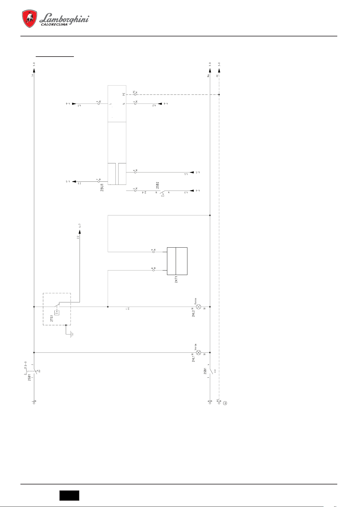
6.2.2 Esquemas eléctricos
Esquema eléctrico
MEGAPREX N 720N ÷ 1060N
1 - (2TS1) Termostato di sicurezza caldaia
2 - (2XT1)
3 - (2BU1) COLLEGAMENTI BRUCIATORE
3 - (2BU1) - A Blocco bruciatore
3 - (2BU1) - B Consenso 1° Fiamma
3 - (2BU1) - C Alimentazione Bruciatore MAX. 3A
Segnalazione per apparecchiature esterne
Segnale 230Vac intervento termostato
sicurezza caldaia
34
IT
cod. 3541O220 - Rev. 00 - 03/2018

MEGAPREX N 720N ÷ 1060N
Esquema de conexionado de la unidad base de control (parte1)
1 - (3P2) Pompa bypass anticondensa caldaia
2 - (3P1) Pompa circolazione acqua
3 - (3B1) Sensore temperatura ritorno acqua caldaia
4 - (3B1) Sensore temperatura ambiente esterno
Max. 2 A
Eventualmente usare come consenso
Max. 2 A
Eventualmente usare come consenso
OPTIONAL
Usare sonda NTC 10K
OPTIONAL
Usare sonda NTC 10K
cod. 3541O220 - Rev. 00 - 03/2018
IT
35

MEGAPREX N 720N ÷ 1060N
Esquema de conexionado de la unidad base de control (parte2)
1 SAFETY-LOOP
2 - (4B1) Sensore temperatura mandata acqua
3 - (4N1) Pannello unità operatore
Ponticellare se non è presente nessun
altro consenso di sicurezza dell’impianto
caldaia
Usare sonda NTC 10K
AVS 37.294
36
IT
cod. 3541O220 - Rev. 00 - 03/2018
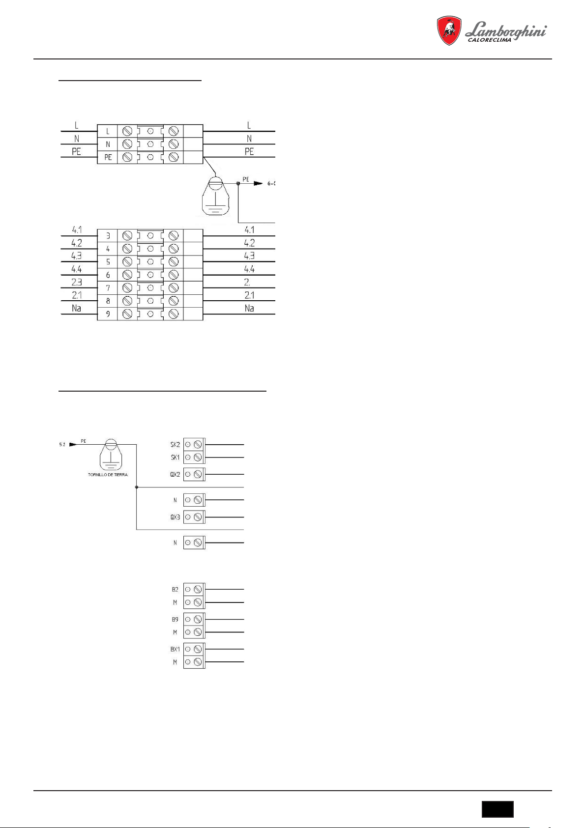
MEGAPREX N 720N ÷ 1060N
Esquema de bornas de conexión del panel
QG - M
Regleta general
Alimentación 230 Vac 50-60Hz Monofasica (Fase)
Alimentación 230 Vac 50-60Hz Monofasica (Neutro)
Alimentación 230 Vac 50-60Hz Monofasica (Conducir a tierra)
BM - 2BU1 - Alimentación quemador 230 Vac 50-60Hz Monofasica (Tierra)
BM - 2BU1 - Alimentación quemador 230 Vac 50-60Hz Monofasica (Fase)
BM - 2BU1 - Alimentación quemador 230 Vac 50-60Hz Monofasica (Neutro)
BM - 2BU1 - Señal 1
BM - 2BU1 - Señal 1
BM - 2BU1 - Señal de bloqueo quemador
BM - 2XT1 - Señal 230Vac termostato seguridad de la caldera
BM - 2XT1 - Señal 230Vac termostato seguridad de la caldera
Esquema de bornas de conexión de la unidad base de control
QG
Borne RVS63.283
BM - Señal de seguridad de la instalación
BM - Señal de seguridad de la instalación
BM - 3P1 - Bomba de agua de la caldera (230 Vac - Fase)
BM - 3P1 - Bomba de agua de la caldera (230 Vac - Tierra)
BM - 3P1 - Bomba de agua de la caldera (230 Vac - Neutro)
BM - 3P2 - Bomba bypass anticondensados (230 Vac - Fase)
BM - 3P2 - Bomba bypass anticondensados (230 Vac - Tierra)
BM - 3P2 - Bomba bypass anticondensados (230 Vac - Neutro)
a
llama quemador
a
llama quemador
I
I
Maxima corriente
I
I
absorbita 3 Aperios
I
I
I
I
I
I
I
Puentear si no es necesario
I
I
I
I
MAX. 2A
I
I
I
I
I
I
MAX. 2A
I
I
I
BM - 4B1 - Sonda temperatura de la caldera
BM - 4B1 - Sonda temperatura de la caldera
BM - 3B3 - Sonda exterior
BM - 3B3 - Sonda exterior
I
I
I
BM - 3B1 - Sonda temperatura de retorno de la caldera
BM - 3B1 - Sonda temperatura de retorno della caldera
cod. 3541O220 - Rev. 00 - 03/2018
OPCIONAL
IT
37
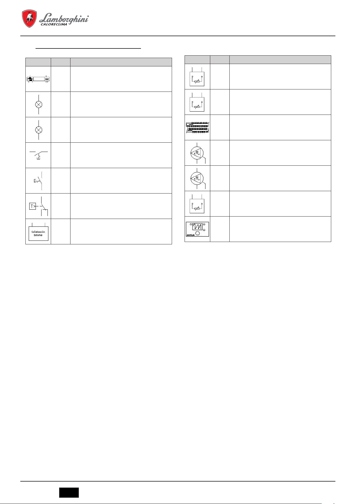
Leyenda símbolos/componentes esquema eléctrico
MEGAPREX N 720N ÷ 1060N
2BU1
BM2Quemador caldera
2HL1
QG2Lámpara alimentación 230Vac panel
2HL2
Lámpara alarma intervencion termostato de
QG
seguridad.
2
2SB1
QG2Interruptor general encendido caldera
2SB2
QG2Interruptor encendido quemador
2TS1
QG2Termostato de seguridad caldera
2XT1
Senal 230Vac intervención termostato segu-
BM
ridad
2
3B1
BM3Sonda temperatura retorno caldera
3B3
BM3Sonda exterior
3N1
Unidad a base del control MASTER (RSV 63
QG
283/109)
3
3P1
BM3Bomba instalación
3P2
BM3Bomba bypass anticondensados
4B1
BM4Sensor temperatura agua ida caldera
4N1
QG4Interfaz usuario Siemens AVS37.294
6.3 Notas sobre las conexiones
El cable de alimentación del panel de tipo FG7 RN-F 3G1,5 de serie ya está conectado a la caja de conexiones. En caso de sustitución usar
un cable adecuado de acuerdo con las normativas vigentes. La alimentación del quemador procede directamente de la caja de conexiones si
se trata del tipo monofásico y con intensidad máxima de 3 A. La alimentación del circulador del agua de la instalación procede directamente de
la caja de conexiones si se trata del tipo monofásico y con intensidad máxima de 3 A. Si el quemador o la bomba tienen una mayor intensidad
de lo que hemos previsto o si se trata de alimentación trifásica, será necesario usar relés de potencia conectados con interfaz a las salidas
previstas en la caja de conexiones.
La autorización de encendido remoto ofrece la posibilidad de encender la caldera a distancia. Se hace un puente si no se usa.La autorización
de seguridad externa de la caldera permite inserta un contacto posterior que provoca el apagado del quemador. Se hace un puente si no se
usa. El contacto para el termostato ambiente sólo actúa sobre el circulador de agua. Se hace un puente si no se usa.
7. PUESTA EN MARCHA
7.1 Controles preliminares
Realizadas las conexiones hidráulicas, eléctricas y del combustible a la caldera, antes de la puesta en marcha debe verificarse que:
- El vaso de expansión y la válvula de seguridad estén correctamente conectados y no se puedan interceptar en modo alguno.
- Los bulbos de los termostatos de regulación, de seguridad de mínima y del termómetro, estén introducidos en las respectivas vainas.
- Los turbohélices se hallen situados en todos los tubos de humos.
- La instalación esté llena de agua y sin nada de aire.
- La bomba o las bombas funcionen correctamente.
- Las conexiones hidráulicas, eléctricas y de seguridad necesarias y del combustible se hayan realizado de acuerdo con las disposiciones
nacionales y locales en vigor.
- El quemador se haya montado de acuerdo con las instrucciones que figuran en el manual del fabricante.
- El voltaje y la frecuencia de red sean compatibles con el quemador y el equipo eléctrico de la caldera.
- La instalación sea capaz de absorber la cantidad de calor que se producirá.
- La bomba de recirculación esté instalada como se describe en el apartado 5.5.5.
38
IT
cod. 3541O220 - Rev. 00 - 03/2018

MEGAPREX N 720N ÷ 1060N
7.2 Primer encendido
Después de la salida positiva de las comprobaciones que se indican en el párrafo anterior, se podrá proceder al primer encendido del quemador
que deberá ser realizada por un técnico en servicio y reconocido por la empresa fabricante del quemador. El técnico asumirá toda la responsabilidad en cuanto al campo de la regulación dentro del campo de potencia declarado y homologado de la caldera. Después de haber abierto
los grifos de corte del combustible y controlado que no haya pérdidas en la red de suministro, poner todos los interruptores en la posición ON
(conectado). El quemador está así preparado para el primer encendido y para la regulación que compete únicamente al técnico autorizado.
Durante el primer encendido se deberá verificar que la puerta, la brida del quemador y las conexiones con la chimenea sean estancas y que la
base de la chimenea tenga una ligera presión negativa. El caudal de combustible deberá corresponder a los datos de la tarjeta de la caldera y
bajo ningún concepto deberá ser superior al valor máximo de la potencia nominal declarada. La temperatura de los humos nunca deberá ser
inferior a 160ºC.
7.3 Apagado de la caldera
- Regular el termostato de ejercicio al mínimo.
- Quitar tensión al quemador y cerrar la alimentación del combustible.
- Dejar funcionar las bombas hasta que las cierre el termostato de mínima.
- Quitar la tensión del cuadro eléctrico.
8. MANTENIMIENTO
8.1 Normas generales
El mantenimiento periódico es esencial para la seguridad, el rendimiento y la duración del aparato.
Todas las operaciones deben ser realizadas por personal cualificado. Cada operación de limpieza y de mantenimiento deberá ir precedida del
cierre de la alimentación de combustible, después de haber quitado la tensión eléctrica.
Para obtener un buen funcionamiento y el máximo rendimiento de la caldera, es necesaria una limpieza regular de la cámara de combustión,
de los tubos de humos y de la cámara de humos.
8.2 Mantenimiento ordinario
El mantenimiento debe establecerse en base al combustible usado, el número de encendidos, las características de la instalación, etc., por lo
que no es posible establecer a priori un intervalo de tiempo entre un mantenimiento y el siguiente.
Como principio aconsejamos los siguientes intervalos de limpieza según el combustible:
- Calderas de gas: un vez al año
- Calderas de gasóleo: dos veces al año
En todos los casos se respetarán las eventuales normas locales respecto al mantenimiento.
Durante las operaciones de mantenimiento ordinario, después de haber retirado los turbohélices se deberá limpiar con el escobillón el haz
tubular y el hogar. Retirar los depósitos acumulados en la cámara de humos por la apertura de las puertas de inspección. En caso de acciones
más enérgicas retirar la cámara de humos posterior y, si estuviera deteriorada, sustituir la junta de estanquidad de humos. Controlar que la
evacuación del agua de condensación no esté obstruida. Se deberá comprobar el buen funcionamiento de los órganos de control y de medición
del generador.
En esta ocasión se deberá registrar la cantidad de agua de reabastecimiento usada, tras haber analizado el agua, realizar un desincrustación
preventiva.
Las sales de calcio y de magnesio disueltas en el agua ordinaria, con repetidos rellenados, da origen a depósitos en la caldera y provocan el
sobrecalentamiento de las chapas con la posibilidad de que se produzcan daños que no se pueden atribuir ni a los materiales ni a la técnica
de fabricación y que, por lo tanto, no están cubiertos por la garantía. Después de haber realizado las operaciones de mantenimiento y limpieza
y el siguiente encendido, verificar la estanquidad de la puerta y de la cámara de humos, en caso de pérdidas del producto de la combustión,
sustituir la junta de estanquidad correspondiente.
Las operaciones realizadas se anotarán en el cuaderno de central.
8.3 Mantenimiento extraordinario
Mantenimiento extraordinario de final de temporada o para largos períodos de inactividad.
Se deben realizar todas las operaciones descritas en el capítulo precedente y además:
- Controlar el estado de desgaste de los turbohélices.
- Después de la limpiar el circuito de humos es conveniente pasar un paño empapado con una solución disuelta de sosa cáustica. Después
de haber dejado secar, repasar todas las superficies con un paño empapado en aceite.
- Se recomienda colocar dentro del hogar sustancias higroscópicas (cal viva, silicogel en pequeños contenedores) y cerrar herméticamente
de manera que no entre aire.
- No vaciar la instalación ni la caldera.
- Proteger con una mezcla de aceite y grafito los tornillos, tuercas y pernos de la puerta.
Las operaciones realizadas se anotarán en el libro de registro de mantenimiento.
cod. 3541O220 - Rev. 00 - 03/2018
IT
39

MEGAPREX N 720N ÷ 1060N
8.4 Limpieza de la caldera (Fig. 13)
Para realizar la limpieza proceder del siguiente modo:
- La caldera viene con cepillo de limpieza para limpiar los tubos de humos.
- Abrir la puerta anterior (1) y extraer las turbohelices (2).
- Limpiar las superficies internas de la cámara de combustión y del recorrido de los humos usando un escobillón (3) u otro utensilio adecuado
para dicho fin.
- Retirar los depósitos acumulados en la cámara de humos por la apertura de la tapa de limpieza (4). En caso de acciones más enérgicas
retirar la cámara de humos (5) sustituyendo la junta de estanquidad antes de realizar el montaje.
- Controlar periódicamente que la evacuación del agua de condensación (6) no esté obstruida.
8.5 Vericación del funcionamiento de la caldera
Antes de realizar el encendido y la prueba funcional de la caldera verificar que:
- las turbohélices se hallen situadas dentro de los tubos de intercambio.
- Los grifos del circuito hidráulico y los del combustible estén abiertos.
- Que haya combustible disponible.
- El vaso de expansión esté cargado adecuadamente.
- La presión en frío, del circuito hidráulico sea superior a 1 bar e inferior al límite máximo previsto por la caldera.
- Los circuitos hidráulicos no contengan aire.
- Se hayan realizado las conexiones eléctricas a la red de alimentación y de los componentes (quemador, bomba, cuadro de mandos, termostatos, etc.).
- La conexión fase-neutro debe ser absolutamente respetada, la conexión de tierra es obligatoria.
Después de haber realizado las operaciones anteriormente descritas, para poner en marcha la caldera es necesario:
- si la instalación está provista de termorregulador o de cronotermostato(s) comprobar que esté(n) en estado “activo”.
- Regular el(los) cronotermostato(s) ambiente(s) o la termorregulación a la temperatura deseada.
- Colocar el interruptor general de la instalación en posición “encendido”.
- Regular el termostato de la caldera situado en el cuadro de mando.
- Colocar el interruptor principal del cuadro de mandos en “on” y verificar el encendido de la señalización verde.
La caldera realizará la fase de encendido y permanecerá en funcionamiento hasta que se alcancen las temperaturas reguladas. En caso de que
se produzcan anomalías de encendido o de funcionamiento la caldera realizará un “PARO DE BLOQUEO” señalado por el piloto rojo situado
sobre el quemador y la señalización roja del cuadro de mando. Después de un “PARO DE BLOQUEO” esperar aproximadamente 30 segundos
antes de restablecer las condiciones de puesta en marcha, para restablecer las condiciones de puesta en marcha pulse el “pulsador/piloto” del
quemador y espere a que se encienda la llama En caso de que no funcione se puede repetir esta operación 2 o 3 veces como máximo, luego
verificar:
- Lo que figura en el manual de instrucciones del quemador.
- El capítulo “VERIFICACIÓN DEL FUNCIONAMIENTO DE LA CALDERA”
- Las conexiones eléctricas previstas en el esquema que se halla junto al cuadro de mando. Una vez realizada la puesta en marcha se debe
verificar que el aparato realiza un paro y la sucesiva nueva puesta en marcha:
- Modificando la regulación del termostato de la caldera.
- Interviniendo en el interruptor principal del cuadro de mandos.
- Interviniendo en el termostato ambiente o en el programador horario o en la termorregulación.
- Verificando la libre y correcta rotación de las bombas.
- Verificando el paro total de la caldera actuando sobre el interruptor general de la instalación.
Si se han respetado todas las condiciones, volver a poner en marcha el aparato, realizar un control de la combustión (análisis de humos), del
caudal del combustible y de la estanqueidad de la junta de la puerta y de la cámara de humos.
8.6 Vericación del funcionamiento del quemador
- Consultar el manual de instrucciones del quemador.
- Seguir todas las reglas de las normas locales en materia de mantenimiento del quemador.
40
IT
cod. 3541O220 - Rev. 00 - 03/2018

MEGAPREX N 720N ÷ 1060N
8.7 Posibles averías y soluciones
Damos a continuación una lista con las indicaciones de las principales averías y anomalías que se pueden producir en la gestión de la caldera,
especificándoselas posibles causas y sus soluciones
ANOMALÍAS
EL GENERADOR SE ENSUCIA FÁCILMENTE
CAUSA: Quemador mal regulado SOLUCIÓN: Controlar la regulación del quemador (análisis humos)
Chimenea obstruida Limpiar el recorrido de los humos y la chimenea
Recorrido del aire del quemador sucio Limpiar voluta aire quemador
EL GENERADOR NO CONSIGUE SUBIR LA TEMPERATURA
CAUSA: Cuerpo del generador sucio SOLUCIÓN: Limpiar el recorrido de los humos
Unión generador/quemador Controlar los datos y las regulaciones
Caudal quemador insuficiente Controlar la regulación del quemador
Termostato de regulación Verificar el correcto funcionamiento
Verificar la temperatura programada
EL GENERADOR EFECTUA UN BLOQUEO DE SEGURIDAD TÉRMICA CON SEÑALIZACIÓN LUMINOSA EN EL CUADRO DE MANDOS
CAUSA: Termostato de regulación SOLUCIÓN: Verificar el correcto funcionamiento
Verificar la temperatura programada
Verificar el cableado eléctrico
Verificar los bulbos de las sondas
Falta de agua Verificar la presión del circuito
Presencia de aire Verificar la válvula de purga
EL GENERADOR ADQUIERE TEMPERATURA PERO EL SISTEMA DE CALEFACTOR ESTÁ FRÍO
CAUSA: Presencia de aire en la instalación SOLUCIÓN: Purgar la instalación
Bomba averiada Desbloquear la bomba
Termostato de mínima (si existe) Verificar la temperatura programada
OLORES DE PRODUCTOS NO QUEMADOS
CAUSA: Dispersión de humos en el ambiente SOLUCIÓN: Verificar la limpieza del cuerpo del generador
Verificar la limpieza del conducto de humos
Verificar el carácter hermético del generador, los conductos de humos y la chimenea
FRECUENTE INTERVENCIÓN DE LA VÁLVULA DE SEGURIDAD
CAUSA: Presión del circuito de la instalación SOLUCIÓN: Verificar la presión de carga
Verificar el circuito de la instalación
Verificar la regulación
Verificar la temperatura programada
Vaso de exspansion de la instalación Verificar
cod. 3541O220 - Rev. 00 - 03/2018
IT
41

MEGAPREX N 720N ÷ 1060N
1. INTRODUCTION ......................................................................................................................................................................... 43
2. GENERAL WARNINGS .............................................................................................................................................................. 43
3. CERTIFICATION ......................................................................................................................................................................... 43
4. TECHNICAL AND CONSTRUCTIONAL CHARACTERISTICS, DIMENSIONS ........................................................................ 43
4.1 Description of the appliance ........................................................................................................................................................................ 43
4.2 Operating principle ....................................................................................................................................................................................... 44
4.3 Technical data - Dimensions - Hydraulic connections ................................................................................................................................. 44
4.4 Identication ................................................................................................................................................................................................. 45
5. INSTALLATION .......................................................................................................................................................................... 45
5.1 Packaging .................................................................................................................................................................................................... 45
5.2 Handling ....................................................................................................................................................................................................... 45
5.3 Installation site (Fig. 4) ................................................................................................................................................................................. 45
5.4 Discharge of combustion products (Fig. 5) .................................................................................................................................................. 46
5.5 Hydraulic connections .................................................................................................................................................................................. 46
5.5.1 Supply water .......................................................................................................................................................................................... 46
5.5.2 System feed/return pipes ....................................................................................................................................................................... 46
5.5.3 System ll/drain pipes ............................................................................................................................................................................ 46
5.5.4 Pipes, expansion vessel and safety valves ............................................................................................................................................ 46
5.5.5 Recirculation pump (Fig. 6) .................................................................................................................................................................... 47
5.6 Adjusting the door (Fig. 7) ........................................................................................................................................................................... 47
5.7 Assembly of the burner (Fig. 8) ................................................................................................................................................................... 47
5.8 Connecting the cooling tube to the ame inspection window (Fig. 9) .......................................................................................................... 47
5.9 Assembling the panels, mod. 720÷1060. Sequence (Fig. 10) ..................................................................................................................... 47
6. CONTROL PANEL (OPTIONAL) ................................................................................................................................................ 48
6.1 LV thermostatic control panel, 2 and 3 burner stages (Fig. 11) ................................................................................................................... 48
6.1.1 Front view of the panel (Fig. 11) ............................................................................................................................................................. 49
6.1.2 Diagram of the terminal block electrical connections ............................................................................................................................. 49
6.1.3 Wiring diagram for burner and single-phase pump ................................................................................................................................ 50
6.2 EBM (Efcient Boiler Management) control panel (Fig. 12) ......................................................................................................................... 53
6.2.1 Panel (Fig. 12) ........................................................................................................................................................................................ 53
6.2.2 Wiring diagrams ..................................................................................................................................................................................... 54
6.3 Notes about the connections ....................................................................................................................................................................... 58
7. COMMISSIONING ...................................................................................................................................................................... 58
7.1 Preliminary checks ....................................................................................................................................................................................... 58
7.2 First ignition ................................................................................................................................................................................................. 59
7.3 Shutting down the boiler .............................................................................................................................................................................. 59
8. MAINTENANCE .......................................................................................................................................................................... 59
8.1 General instructions ..................................................................................................................................................................................... 59
8.2 Routine maintenance ................................................................................................................................................................................... 59
8.3 Special maintenance ................................................................................................................................................................................... 59
8.4 Cleaning the boiler (Fig. 13) ........................................................................................................................................................................ 60
8.5 Checking boiler operation ............................................................................................................................................................................ 60
8.6 Checking burner operation .......................................................................................................................................................................... 60
8.7 Troubleshooting ........................................................................................................................................................................................... 61
42
IT
cod. 3541O220 - Rev. 00 - 03/2018

MEGAPREX N 720N ÷ 1060N
1. INTRODUCTION
Dear customer: Thank you for choosing a MEGAPREX N boiler. This manual was written to provide information, warnings, and advice
on the proper installation, use, and maintenance of the boiler.
Please read it carefully and save it for future reference. It is in your own interest to carefully follow and observe the instructions given in this
manual, in order to fully enjoy this high-quality product.
Failure to comply with and observe the instructions contained in this manual exonerates the manufacturer from all liability, and invalidates the
warranty.
2. GENERAL WARNINGS
The instructions manual is an integral part of the product, and provides a description of all instructions that must be observed during the
installation, use and maintenance phase.
- This appliance must only be used for the purpose for which it was expressly intended.
- This appliance is intended to heat water to below-boiling temperatures at atmospheric pressure, and must be connected to a central
heating and/or domestic hot water distribution system, in accordance with its characteristics, performance, and heat output.
- Before installation, check that the boiler has not been damaged during handling and transport.
- The installation must be performed by duly qualified personnel, in accordance with current standards.
- Before performing any cleaning or maintenance operations, unplug the appliance from the mains power supply.
- LAMBORGHINI is not liable for any damage to people or things due to errors in installation, adjustment, maintenance, or improper use.
- The boiler and corresponding system must be commissioned by authorized personnel.
- Commissioning is performed in order to verify proper operation of all adjustment and control devices.
- Qualified personnel must be contacted if the appliance is not used for an extended period.
Standards
The installer must observe current local regulations with regard to: the site chosen for the installation of the boiler, compliance with required
ventilation conditions, the tightness of the connection to the chimney, connections to fuel lines, electrical systems, and any other relevant safety
standards.
Warranty conditions
The warranty is only valid if the standards and recommendations for use contained in this manual are observed. Any non-compliance or
modification will void the warranty. The warranty does not cover damage caused by acidic condensate corrosion from the products of combustion,
or the formation of deposits caused by the use of hard or aggressive water, as these are caused solely by system operation.
3. CERTIFICATION
The CE marking certifies that the products meet the essential requirements of the applicable directives.
The declaration of conformity may be requested from the manufacturer.
PRODUCT IDENTIFICATION CODES
MEGAPREX N 720N 0QIJHBXD
MEGAPREX N 820N 0QIJIBXD
COUNTRIES OF DESTINATION: IT - ES - RU
MEGAPREX N 940N 0QIJJBXD
MEGAPREX N 1060N 0QIJKBXD
4. TECHNICAL AND CONSTRUCTIONAL CHARACTERISTICS, DIMENSIONS
4.1 Description of the appliance
The construction of the boilers in the MEGAPREX N series guarantees high power and efficiency with low flue gas temperatures, thus ensuring
low polluting emissions. They are manufactured in accordance with standard EN 303, part 1. The main technical elements of the design are:
- careful design of geometries to achieve an optimum ratio between combustion volumes and heat exchange surfaces.
- the choice of materials used, to ensure long boiler life.
The boilers feature pressurized combustion with 2 flue passes, a horizontal-cylinder configuration, and flame reversal in the furnace, completely
surrounded by the water that cools it. The flame produced by the burner is reversed peripherally toward the front, where the flue gas enters the
tube bundle, featuring turbulators to create a swirling path that increases the heat exchange by convection. On leaving the tube bundle, the flue
gas enters the rear chamber and is transferred to the chimney.
The boilers are fitted with a door featuring hinges that can be reversed for opening to the right or left, and is adjustable in both height and
depth. The body is insulated with a thick layer of glass wool, and covered with a further layer of tearproof material. The external finish consists
of painted steel panels.
The boilers feature two 1/2” fittings for bulb sheaths (able to house 3 bulbs each). The pre-wired control panel is located above the boiler, and
allows for automatic operation.
cod. 3541O220 - Rev. 00 - 03/2018
IT
43

MEGAPREX N 720N ÷ 1060N
4.2 Operating principle
MEGAPREX N boilers are fitted with a closed cylindrical furnace, in which the flame produced by the burner is reversed peripherally
toward the front. From there, the burned gas enters the fire tubes. At the outlet, the gas is collected in the smokebox, and is then sent to the
chimney. The combustion chamber is always pressurized during burner operation. For the pressure values, see Table 1, in the column Flue gas
side pressure drop. The flue and flue stack fitting must be made in accordance with current standards and legislation, using rigid pipes that are
resistant to high temperatures, condensate, and mechanical stress, and are airtight. (Fig. 1)
4.3 Technical data - Dimensions - Hydraulic connections
MEGAPREX N 720N 820N 940N 1060N
Rated power
Combustion chamber power
Useful efciency at 100% maximum power % 92.71 93.10 92.95 93.05
Useful efciency at 30% maximum power % 93.60 94.40 94.20 96.75
Total boiler capacity liters 735 735 850 1250
Water side load loss
Flue side load loss mbar 4.5 5.6 5.4 6
Maximum operating pressure bar 6 6 6 6
Dry weight kg 1250 1250 1420 1580
DIMENSIONS
HOT WATER FLOW T1 DN 100 DN 100 DN 100 DN 125
HOT WATER RETURN T2 DN 100 DN 100 DN 100 DN 125
EXPANSION TANK CONNECTION T3 2 1/2" 2 1/2" 2 1/2" 3"
BOILER DRAIN T4 1" 1" 1" 1"
FLUE OUTLET T5 Øe mm 340 340 340 400
min kW 468 533 611 667
max kW 720 820 940 1000
min kW 502 566 651 717
max kW 777 881 1011 1075
mbar 32 40 51 65
mbar 18 25 25 33
mbar 10 18 16 20
A mm 1250 1250 1250 1430
B mm 1784 1784 2024 2028
C mm 1335 1335 1335 1515
D mm 162 162 162 162
E mm 212 212 212 240
F mm 219 219 219 214
G mm 830 830 830 900
H mm 565 565 565 670
I mm 2215 2215 2455 2482
L mm 196 196 196 196
L1 mm 227 227 227 227
M mm 1400 1400 1400 1580
N mm 223 223 223 227
O mm 440 440 480 480
P mm 700 700 900 900
Q mm 1200 1200 1200 1380
R mm 1752 1752 1992 1992
44
IT
cod. 3541O220 - Rev. 00 - 03/2018

MEGAPREX N 720N ÷ 1060N
Key (Fig. 2)
1 Control panel T2 Central heating return
2 Burner bracket T3 Expansion vessel connection
3 Smokebox cleaning door T4 Boiler drain
4 Flame inspection window T5 Flue gas outlet
T1 Central heating feed T6 Burner connection
4.4 Identication
The boiler can be identified by the (Fig. 3):
- Document envelope
This can be found inside the boiler furnace, next to the instrument panel:
- Technical manual
- Warranty certificate
- Rating label
The rating label shows the technical data and performance information for the appliance.
It is affixed to the outside of the instrument panel.
Alterations, removal or absence of identification labels, or any other circumstance that makes it difficult to accurately identify the product, can
cause problems during installation and maintenance operations.
5. INSTALLATION
5.1 Packaging
MEGAPREX N boilers are supplied with the door, smokebox and insulation installed, and the panels in a separate cardboard box.
The instrument panel and ceramic fiber padding for the burner nozzle can be found inside the combustion chamber.
The instrument panel is supplied in a cardboard box located inside the combustion chamber.
5.2 Handling
MEGAPREX N boilers are equipped with eyebolts for lifting. Handle the unit carefully, using suitable equipment for the weight to be lifted.
Before connecting the boiler, remove the wooden base.
5.3 Installation site (Fig. 4)
MEGAPREX N boilers must be installed in rooms to be used exclusively for that purpose, in accordance with current technical standards
and legislation, and featuring adequately sized ventilation openings. The ventilation openings must be permanent, directly open to the outside,
and located in both high and low positions, in accordance with current standards. The location of the ventilation openings and fuel supply,
electrical power distribution and lighting circuits must comply with current legal provisions for the type of fuel used. To facilitate the cleaning of
the flue gas circuit, space must be left at the front of the boiler, greater than or equal to the length of the boiler body, and no less than 1,300 mm.
With the door open 90º, verify that the distance between the door and adjacent wall (X) is at least equal to the length of the burner.
The boiler support surface must be perfectly horizontal. A flat cement base is recommended, able to support the full weight of the boiler plus the
water content. For the base dimensions, see the R x Q distances (dimension table). If the burner is powered by a fuel gas with a specific weight
higher than air, the electrical parts must be located at least 500 mm from the floor. These boilers cannot be installed outdoors because they are
not designed to operate outside, and are not equipped with automatic frost protection systems.
INSTALLATION IN OLD SYSTEMS
If the boiler is to be installed in an old system, verify that:
- The chimney is suitable for the temperature of the combustion products, has been calculated and manufactured in accordance with current
standards, and is airtight, insulated, and not blocked or choked.
- The electrical system has been installed by qualified personnel, in accordance with current standards.
- The fuel supply line and any tanks have been installed in accordance with current standards.
- The expansion vessel(s) can completely absorb the expansion of the fluid contained in the system.
- The flow-rate, static pressure, and direction of flow of the circulation pumps are suitable.
- The system is clean, free of slime and deposits, vented and watertight.
- A treatment system is available for supply/top-up water (see reference values).
cod. 3541O220 - Rev. 00 - 03/2018
IT
45

MEGAPREX N 720N ÷ 1060N
5.4 Discharge of combustion products (Fig. 5)
The flue and flue stack fitting must be made in accordance with current standards and legislation, using rigid pipes that are resistant to high
temperatures, condensate, and mechanical stress, and are airtight.
The flue must ensure the minimum negative pressure established by current standards, with “zero” pressure considered at the fitting to the flue.
Unsuitable or incorrectly sized flues can increase the noise produced by combustion, cause condensation problems, and negatively affect the
combustion parameters. Uninsulated flues are a source of danger. The joint seals must be made with materials that can resist temperatures
of at least 250ºC. Suitable points for measuring the flue gas temperature and analyzing the products of combustion must be prepared in the
connection between the boiler and the flue.
For the cross-section and height of the chimney, refer to current local and national regulations.
5.5 Hydraulic connections
5.5.1 Supply water
The chemical characteristics of the system and top-up water are fundamental for the correct operation and safety of the boiler. The water must
be treated using suitable systems. The values shown in the table below can be used as a reference.
TOTAL HARDNESS ppm 10
ALKALINITY mg/l CaCO3 750
PH 8÷9
SILICA ppm 100
CHLORIDES ppm 3500
The water used in the heating system absolutely must be treated in the following cases:
- Very large systems
- Very hard water
- Frequent addition of water to top up the system
If it becomes necessary to partially or completely empty the system, it should be refilled with treated water. To control the volume of water
refilled, a meter should be installed on the pipe. The most common issues arising in heating systems are:
- Lime scale deposits
Lime scale accumulates at the points where the wall temperature is highest. Due to their low heat conductivity, lime scale deposits cause a
reduction in heat exchange. Even if they're only a few millimeters thick, the heat exchange between the flue gas and the water is limited, which
increases the temperature of the parts exposed to the flame and causes cracks in the tube plate.
- Corrosion on the water side
Corrosion of the metal surfaces on the water side of the boiler is caused by the dissolution of iron into its ions. The presence of dissolved gases,
particularly oxygen and carbon dioxide, plays an important role in this process. Softened and/or demineralized water provides protection against
deposits, but not against corrosion. The water must therefore be treated with corrosion inhibitors.
5.5.2 System feed/return pipes
The dimensions of the feed and return pipes for each boiler model are indicated on the DIMENSIONS table. Make sure the system has a
sufficient number of vent openings.
The boiler fittings must not support the weight of the connection pipes to the system. Appropriate supports must be installed for this purpose.
5.5.3 System ll/drain pipes
For filling and draining the boiler, a cock can be connected to fitting T4 on the back (see DIMENSIONS, Fig. 2).
5.5.4 Pipes, expansion vessel and safety valves
MEGAPREX N boilers are suitable for operation with forced water circulation, with the expansion vessel open or closed. An expansion
vessel is always required to compensate for the increase in water volume due to heating. In the first case, the height of the hydrostatic column
must be at least 3 meters above the boiler body. Its capacity must be sufficient to contain the increase in volume of all water in the system,
between the surface of the water in the vessel and the overflow pipe. Tall, narrow vessels are preferable, as they ensure minimum contact
between the water surface and the air, thus reducing evaporation. In the second case, the capacity of the closed expansion vessel must be
calculated considering:
- the total volume of water contained in the system
- the maximum operating pressure of the system
- the maximum operating pressure of the expansion vessel
- the initial pre-charge pressure of the expansion vessel
- the boiler's maximum operating temperature (the maximum temperature on the thermostat fitted on the panel is 90ºC; use 100ºC to perform
46
IT
cod. 3541O220 - Rev. 00 - 03/2018
MEGAPREX N 720N ÷ 1060N
this calculation).
The expansion pipe connects the expansion vessel to the system. This pipe will start at the T3 fitting (see the Dimensions table), and must not
be fitted with on-off valves. At fitting T3, or within 0.5 m of the first flange on the outlet pipe, install a safety valve suitable for the capacity of the
boiler and in compliance with current local standards. No type of shut-off device may be installed between the boiler and the safety valves, and
these valves should be set to operate when the maximum permitted operating pressure is exceeded.
5.5.5 Recirculation pump (Fig. 6)
Condensation of the water vapor contained in the flue gas leaving the boiler (condensate) occurs when the return water temperature is below
50ºC. This is significant, particularly when the boiler is turned on in the morning after being off all night. Condensate is acidic and corrosive, and
will damage the metal plating on the boiler over time. It is therefore advisable to install a recirculation pump with an anti-condensation feature,
to be fitted between the feed and return fittings, upstream of any mixing valve. While the system is operating, the pump must ensure a flow-rate
of 20 to 30% of the total. The (anti-condensation) recirculation pump is controlled using the Low-Temperature Thermostat Panel (optional). The
bulb for the corresponding thermostat must be fitted at the return (using a sheath that must be added by the installer of that pipe).
5.6 Adjusting the door (Fig. 7)
On all pressurized boilers, it's possible to adjust and reverse the side where the door opens.
Opening
To set the side of the door, simply tighten lock nuts 2 and 4 against nuts 1 and 3.
To reverse the side where the door opens, tighten lock nuts 2 and 4 on the opposite side.
Closing
Loosen lock nuts 2 and 4, tighten nuts 1 and 3 as needed, and retighten lock nuts 2 and 4.
Positioning
After installing the burner, the door must be positioned. This can be done by loosening nuts 1 and 3 and set screw 5, and using nut 6 to adjust the
height. This must be done so that the entire rope seal presses against the plate, by tightening nuts 1 and 3.
5.7 Assembly of the burner (Fig. 8)
The assembly of the burner at the boiler door must ensure perfect tightness for the products of combustion. Once the burner is installed on the
boiler, the space between the burner nozzle and the refractory material on the door must be filled with the ceramic fiber padding (A) provided.
This prevents the door from overheating, which would result in irreversible warping. The fuel connections to the burner must be placed so that
the boiler door can open completely with the burner installed.
It is advisable to place a rigid supporting base under the burner to prevent its full weight from negatively affecting the door.
RSW L min. (mm) L max. (mm) S
720-1060 N 320 390 239
5.8 Connecting the cooling tube to the ame inspection window (Fig. 9)
The flame inspection window is equipped with a pressure fitting (1). Once the interior screw is loosened, it must be connected to outlet 2 on the
burner using a silicone hose or copper pipe. This allows the air blown back by the fan to cool the glass on the window and prevent it from turning
black. Failure to connect the hose or pipe to the window can cause the glass to break.
When disassembling the window for cleaning, check the condition of the seals, replacing them if necessary. After closing, verify tightness.
5.9 Assembling the panels, mod. 720÷1060. Sequence (Fig. 10)
a) Carefully position the side panels (pos. 1, 2 - 3 and 4), hooking them onto the supports on the boiler.
b) Assemble the U (pos. 12).
c) Attach the control panel to the top front panel (pos. 5).
d) Rest the top panel (pos. 5), which includes the control panel, against the side panel (pos. 1), which includes springs, closing pins and nuts
(pos. 9-10-11).
e) Insert the instrument bulbs in the sheaths (pos. 13) and make the electrical connection from the control panel to the mains, burner, any
pumps, etc. It is advisable to insert the probes fully into the sheaths to improve contact. Then secure the capillary tubes with the springs. Close
the cover on the electrical panel and pass the burner plug through the openings on the previous plate (pos. 14).
f) Install the top panels (pos. 6-7-8), hooking them onto the side panels (pos. 2-3-4), which include springs, closing pins and nuts (pos. 9-10-11).
g) Attach the front panel (pos. 15) to the front door using the screws (pos. 16) and nuts (pos. 17). The panel must be fitted before installing the
burner.
cod. 3541O220 - Rev. 00 - 03/2018
IT
47

MEGAPREX N 720N ÷ 1060N
6. CONTROL PANEL (OPTIONAL)
C16015180 – LV thermostatic control panel, 2 stages
C16015190 – LV thermostatic control panel, 3 stages
C16015150 – EBM (Efficient Boiler Management) control panel
6.1 LV thermostatic control panel, 2 and 3 burner stages (Fig. 11)
(The diagrams shown below are valid for all three panels.)
The panel is not supplied. It's made of plastic with protection index IP40, and houses adjustment and safety instruments. The LV panels include
a thermostat signal to control the anti-condensation pump, as described in paragraph 5.5.5. The electrical system for the boiler must be:
- designed and installed by qualified personnel and connected to a grounding system in accordance with current legal standards.
- suitable for the maximum power absorbed by the boiler, using electrical cables with the appropriate cross-section.
The ground wire in the power cables and cables connecting to the boiler must be several mm longer than the other wires in the same cable.
For connections between the burner, electrical panel and electrical power supply, the use of H07 RN-F cables is recommended for visible
connections. For other types of systems, or for special environmental situations, consult current standards. The composition and diameter of the
wires is calculated based on the power absorbed by the burner. To access the instruments, rotate the front panel (A). To access the connection
terminals and unwind the capillary tubes from the thermostats and thermometer, remove the top panel (B) after first removing the 2 side screws
(C). The control thermostats (12-13 - Fig. 12) can be set by the user, using the knob at the front. The safety thermostat has a fixed setting and
manual reset. The following are compulsory:
- use a two-pole, thermal-magnetic overload switch, mains disconnecting switch, in compliance with CEI-EN standards (minimum contact
opening of 3 mm)
- observe the polarity L1 (Phase) - N (Neutral)
- use cables with a cross-section greater than or equal to 1.5 mm2, including terminals
- refer to the wiring diagrams in this instructions manual for any operations on the electrical system
- effectively ground the appliance
- it is forbidden to use water hoses to ground the appliance.
The manufacturer is not liable for any damage caused by the failure to ground the appliance, or for non-compliance with the wiring diagrams.
48
IT
cod. 3541O220 - Rev. 00 - 03/2018

MEGAPREX N 720N ÷ 1060N
6.1.1 Front view of the panel (Fig. 11)
Key
1
System pump ON switch
2
Burner ON switch
3
Boiler ON switch
4
Test button
5
Safety pressure switch reset button
6
Boiler water temperature
7
Boiler ON LED pilot
6.1.2 Diagram of the terminal block electrical connections
8
1st burner stage LED pilot
9
2nd burner stage LED pilot
10
Burner block LED pilot
11
Safety pressure switch LED pilot
12
2nd stage TR1 thermostat setting
13
1st stage TR1 thermostat setting
14
Space for temperature controller
(*) Only LV panels
(**) Only 3-Stage LV panels
L
N 14
Control panel power supply
3
Burner power supply
4 17
5
1st phase thermostat
6 19
1st phase thermostat
8 21
9 Shutdown pilot 22
nd
10 2
11
12
phase operation pilot 23
System pump power supply
cod. 3541O220 - Rev. 00 - 03/2018
13
Remote boiler start
(jumper if not present)
15
Remote boiler safety
(jumper if not present)
16
Room thermostat
18
Signal for anti-condensation pump7
20
rd
3
phase thermostat
IT
49
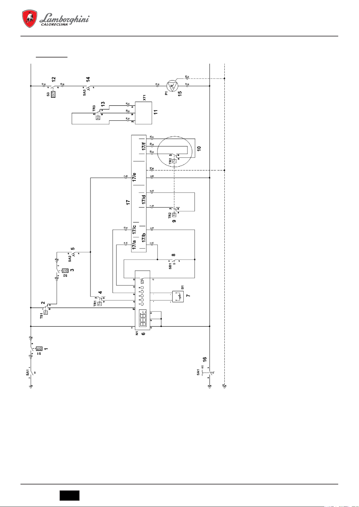
6.1.3 Wiring diagram for burner and single-phase pump
Wiring diagram
MEGAPREX N 720N ÷ 1060N
1 - (S1) Remote start enabling signal
2 - (TS1) Boiler safety thermostat
3 - (S2) External safety enabling signal
4 - (TR1) 1
5 - (SA2) Burner ON switch
6 - (N1) Digital thermometer
7 - (B1) Boiler water temperature probe
8 - (SB1) Test thermostat button
9 - (TR2) 2
10 - (TR2)
11 - (XT1) Anti-condensation pump management con-
12 - (S3) Room thermostat
13 - (TR3) Thermostat
14 - (SA3) Circulator ON switch
15 - (P1) Water circulation pump
16 - (SA1) Boiler ON switch
17 BURNER CONNECTIONS
17 - (17/a) Burner block
17 - (17/b) Second flame
17 - (17/c) 1
17 - (17/d) 2
17 - (17/e) Burner power supply
17 - (17/f) 3
st
boiler flame thermostat
nd
boiler flame thermostat
rd
3
boiler flame thermostat
ONLY FOR 3
tact
ONLY FOR LOW-TEMPERATURE PANEL
st
flame enabling signal
nd
flame enabling signal
rd
flame enabling signal
rd
FLAME PANEL
50
IT
cod. 3541O220 - Rev. 00 - 03/2018

MEGAPREX N 720N ÷ 1060N
Connection diagram
cod. 3541O220 - Rev. 00 - 03/2018
IT
51

Terminal blocks
Maximum current
input 3 amperes
IIIIIIIIIII
MEGAPREX N 720N ÷ 1060N
Maximum current
input 3 amperes
IIIII
Jumper if not present
I
III
Jumper if not present
III
Jumper if not present
III
ONLY FOR LOW-TEMPERATURE PANEL
IIIII
IIIII
ame burner operation enabling signal
230 Vac 50-60 Hz single-phase power supply (phase)
230 Vac 50-60 Hz single-phase power supply (neutral)
230 Vac 50-60 Hz single-phase power supply (ground)
230 Vac 50-60 Hz single-phase burner power supply (ground)
st
230 Vac 50-60 Hz single-phase burner power supply (phase)
230 Vac 50-60 Hz single-phase burner power supply (neutral)
1
1st ame burner operation enabling signal
2nd ame burner operation enabling signal
2nd ame burner operation enabling signal
Burner shutdown signal
Burner shutdown signal
230 Vac 50-60 Hz single-phase system pump power supply (ground)
burner ame [ Com ]
burner ame [ NO ]
burner ame [ NC ]
rd
rd
rd
/ 3
/ 3
/ 3
nd
nd
nd
230 Vac 50-60 Hz single-phase system pump power supply (phase)
230 Vac 50-60 Hz single-phase system pump power supply (neutral)
Remote boiler start enabling signal
Remote boiler start enabling signal
External boiler safety enabling signal
External boiler safety enabling signal
Room thermostat
Room thermostat
Boiler anti-condensation pump enabling signal [ Com ]
Boiler anti-condensation pump enabling signal [ NO ]
Boiler anti-condensation pump enabling signal [ NC ]
Thermostat 2
Thermostat 2
Thermostat 2
52
IT
cod. 3541O220 - Rev. 00 - 03/2018

MEGAPREX N 720N ÷ 1060N
IT
Temperatura mandata acqua caldaia
Interruttore bruciatore
IT
Interruttore bruciatore
IT
Temperatura mandata acqua caldaia
Strumento stato caldaia/Temperatura acqua
Interruttore bruciatore
Interruttore circolatore
IT
Interruttore bruciatore
IT
Temperatura mandata acqua caldaia
Strumento stato caldaia/Temperatura acqua
Circolatore acqua impianto
Interruttore bruciatore
Interruttore circolatore
Pulsante test
IT
Interruttore bruciatore
Interruttore circolatore
Pulsante test
IT
Temperatura mandata acqua caldaia
Strumento stato caldaia/Temperatura acqua
Circolatore acqua impianto
Consenso accensione remoto
Interruttore bruciatore
Interruttore circolatore
Pulsante test
Termostato 1° stadio bruciatore
IT
Interruttore bruciatore
Interruttore circolatore
Pulsante test
Termostato 1° stadio bruciatore
IT
Temperatura mandata acqua caldaia
Strumento stato caldaia/Temperatura acqua
Circolatore acqua impianto
Consenso accensione remoto
Interruttore bruciatore
Interruttore circolatore
Pulsante test
Termostato 1° stadio bruciatore
IT
Interruttore bruciatore
Interruttore circolatore
Pulsante test
Termostato 1° stadio bruciatore
Termostato 2° stadio bruciatore
Termostato di sicurezza caldaia
IT
Temperatura mandata acqua caldaia
Strumento stato caldaia/Temperatura acqua
Circolatore acqua impianto
Consenso accensione remoto
Consenso di sicurezza esterno
Termostato ambiente
Interruttore accensione caldaia
Interruttore bruciatore
Interruttore circolatore
Pulsante test
Termostato 1° stadio bruciatore
Termostato 2° stadio bruciatore
Termostato di sicurezza caldaia
Key to the symbols/components on the wiring diagram
B1
QG2Water outlet temperature
N1
QG2Boiler status/Water temperature instrument
P1
QG2System water circulator
S1
QG2Remote start enabling signal
S2
QG2External safety enabling signal
S3
QG2Room thermostat
SA1
QG2Boiler ON switch
SA2
QG2Burner switch
SA3
QG2Circulator switch
SB1
QG2Test button
TR1
QG21st burner phase thermostat
TR2
QG22nd/3rd burner phase thermostat
TS1
QG2Boiler safety thermostat
6.2 EBM (Efcient Boiler Management) control panel (Fig. 12)
C16015150 – EBM (Efficient Boiler Management) control panel
6.2.1 Panel (Fig. 12)
The EBM control panel is not supplied as standard equipment with the boiler. It provides the following features:
- Operating language selection
- Selection of the mode of operation: heating, economical operation, timer and vacation
- Control of the boiler pump
- Control of the anti-condensation bypass pump
- Single-stage burner control
- Two-stage burner control
- Modulating burner control
- Hour meter for the burner stages
- Display of the boiler settings
- Display of the alarms produced
- Climate feature (with optional exterior probe)
This can control a system with a maximum configuration of:
- A high-temperature area with pump control
- One or two low-temperature areas with a mixer valve and pump
- A DHW storage tank, pump controlled by tank temperature
Other applications:
Can be used to connect up to 16 boilers in cascade, in a master-slave system. Can be integrated into a solar system.
cod. 3541O220 - Rev. 00 - 03/2018
IT
53

6.2.2 Wiring diagrams
Wiring diagram
MEGAPREX N 720N ÷ 1060N
1 - (2TS1) Boiler safety thermostat
2 - (2XT1)
3 - (2BU1) BURNER CONNECTIONS
3 - (2BU1) - A Burner shutdown
3 - (2BU1) - B 1st flame enabling signal
3 - (2BU1) - C Burner power supply MAX. 3A
Signalling for external equipment
Boiler safety thermostat intervention
230 Vac signal
54
IT
cod. 3541O220 - Rev. 00 - 03/2018

MEGAPREX N 720N ÷ 1060N
Connection diagram for the base control unit (part 1)
1 - (3P2) Boiler anti-condensation bypass pump
2 - (3P1) Water circulation pump
3 - (3B1) Boiler water return temperature sensor
4 - (3B1) External ambient temperature sensor
Max. 2 A
If necessary, use as an enabling signal
Max. 2 A
If necessary, use as an enabling signal
OPTIONAL
Use 10K NTC probe
OPTIONAL
Use 10K NTC probe
cod. 3541O220 - Rev. 00 - 03/2018
IT
55

Connection diagram for the base control unit (part 2)
MEGAPREX N 720N ÷ 1060N
1 SAFETY-LOOP
2 - (4B1) Boiler water feed temperature sensor
3 - (4N1) Operator unit panel
Jumper if there’s no other enabling safety
signal for the system
Use 10K NTC probe
AVS 37.294
56
IT
cod. 3541O220 - Rev. 00 - 03/2018

MEGAPREX N 720N ÷ 1060N
Diagram of connection terminals on the panel
QG - M
General terminal block
230 Vac 50-60 Hz single-phase power supply (Phase)
230 Vac 50-60 Hz single-phase power supply (Neutral)
230 Vac 50-60 Hz single-phase power supply (Ground)
BM - 2BU1 - 230 Vac 50-60 Hz single-phase burner power supply (Ground)
BM - 2BU1 - 230 Vac 50-60 Hz single-phase burner power supply (Phase)
BM - 2BU1 - 230 Vac 50-60 Hz single-phase burner power supply (Neutral)
BM - 2BU1 - 1
BM - 2BU1 - 1
BM - 2BU1 - Burner shutdown signal
BM - 2XT1 - 230 Vac boiler safety thermostat signal
BM - 2XT1 - 230 Vac boiler safety thermostat signal
Diagram of connection terminals on the base control unit
QG
Terminal RVS63.283
BM - System safety signal
BM - System safety signal
BM - 3P1 - Boiler water pump (230 Vac - Phase)
BM - 3P1 - Boiler water pump (230 Vac - Ground)
BM - 3P1 - Boiler water pump (230 Vac - Neutral)
BM - 3P2 - Anti-condensation bypass pump (230 Vac - Phase)
BM - 3P2 - Anti-condensation bypass pump (230 Vac - Ground)
BM - 3P2 - Anti-condensation bypass pump (230 Vac - Neutral)
st
burner ame enabling signal
st
burner ame enabling signal
I
I
Maximum current
I
I
input 3 amperes
I
I
I
I
I
I
I
Jumper if not present
I
I
I
I
MAX. 2A
I
I
I
I
I
I
MAX. 2A
I
I
I
BM - 4B1 - Boiler temperature probe
BM - 4B1 - Boiler temperature probe
BM - 3B3 - External probe
BM - 3B3 - External probe
BM - 3B1 - Boiler return temperature probe
BM - 3B1 - Boiler return temperature probe
cod. 3541O220 - Rev. 00 - 03/2018
I
I
OPTIONAL
I
IT
57

Key to the symbols/components on the wiring diagram
MEGAPREX N 720N ÷ 1060N
2BU1
BM2Boiler burner
2HL1
QG2230 Vac panel power supply lamp
2HL2
QG2Safety thermostat operation alarm lamp
2SB1
QG2Main boiler ON switch
2SB2
QG2Burner ON switch
2TS1
QG2Boiler safety thermostat
2XT1
BM2230 Vac safety thermostat operation signal
3B1
BM3Boiler return temperature probe
3B3
BM3External probe
3N1
QG3MASTER (RSV 63 283/109) base control unit
3P1
BM3System pump
3P2
BM3Anti-condensation bypass pump
4B1
BM4Boiler feed water temperature sensor
4N1
QG4Siemens AVS37.294 user interface
6.3 Notes about the connections
The panel power cable, type FG7 RN-F 3G1.5, is already connected to the terminal block as standard equipment. In the event of replacement,
be sure to use a suitable cable in accordance with current legislation. The power supply to the burner is taken directly from the terminal block, if
single-phase and with a maximum current input of 3 A. The power supply to the system water circulator is taken directly from the terminal block,
if single-phase and with a maximum current input of 3 A. If the current input of the burner or pump is higher than envisaged, or the power supply
is three-phase, power relays must be connected to the outputs on the terminal block.
The remote start enabling signal makes it possible to start the boiler remotely. This is jumpered if not used. The external boiler safety enabling
signal makes it possible to insert a further contact that turns off the burner. This is jumpered if not used. The contact for the room thermostat
only acts on the water circulator. This is jumpered if not used.
7. COMMISSIONING
7.1 Preliminary checks
Once the hydraulic, electrical and fuel connections to the boiler have been made, the following must be verified before starting the boiler:
- The expansion vessel and safety valve are properly connected and cannot be blocked in any way.
- The bulbs for the control and minimum safety thermostats and thermometer have been secured in the corresponding sheaths.
- The turbulators have been positioned in all the flues.
- The system is filled with water and completely vented of air.
- The pump or pumps are operating correctly.
- The hydraulic, electrical, safety device, and fuel connections have been performed in accordance with current local and national legislation.
- The burner has been installed according to the instructions in the manufacturer's manual.
- The mains voltage and frequency are compatible with the burner and the boiler's electrical equipment.
- The system is able to absorb the amount of heat that will be produced.
- The recirculation pump is installed as described in section 5.5.5.
58
IT
cod. 3541O220 - Rev. 00 - 03/2018

MEGAPREX N 720N ÷ 1060N
7.2 First ignition
After successfully completing the checks indicated in the previous paragraph, the burner may be ignited for the first time. This must be done by a
technician authorized by the manufacturer of the burner. The technician will be fully responsible for the field of calibration within the declared and
approved output range of the boiler. After opening the fuel on-off cocks and checking that there are no leaks in the supply line, place all switches
in the ON position. The burner is now ready for first ignition, and for the adjustments that may only be made by the authorized technician.
On first ignition, check that the door, burner flange and connections to the chimney are tight, and that there's a slight negative pressure at
the base of the flue. The fuel rate must match the information on the boiler's rating card. Under no circumstances may it exceed the declared
maximum rated output value. The temperature of the flue gas must never fall below 160ºC.
7.3 Shutting down the boiler
- Set the operating thermostat to the minimum value.
- Turn off the power to the burner and cut off the fuel supply.
- Let the pumps operate until they are stopped by the temperature controller.
- Disconnect the power to the electrical panel.
8. MAINTENANCE
8.1 General instructions
Periodic maintenance is essential for the safety, efficiency, and long life of the appliance.
All operations must be carried out by qualified personnel. Before performing any cleaning or maintenance operations, the fuel supply must be
cut off after first shutting off the power.
For proper boiler operation and maximum efficiency, the combustion chamber, fire tubes and smokebox must be cleaned regularly.
8.2 Routine maintenance
Maintenance must be scheduled based on the fuel used, number of ignitions, system characteristics, etc. Maintenance intervals can therefore
not be determined in advance.
As a reference, we recommend the following cleaning intervals, depending on the fuel:
- Gas boilers: Once a year
- Gas oil boilers: Twice a year
In any case, local maintenance standards must be observed.
During routine maintenance, remove the turbulators and then brush the tube bundle and furnace. Remove the deposits accumulated in the
smokebox through the open inspection doors. For more thorough cleaning, remove the rear smokebox. If worn, replace the flue gas seal. Check
that the condensate drain is not blocked. Make sure the control and measurement devices on the boiler are working correctly.
On this occasion, record the amount of top-off water used. After analyzing the water, perform a preventive descaling.
After repeated refills, the calcium and magnesium salts dissolved in the water will produce deposits in the boiler, cause the metal plates to
overheat, and can cause damage that is not attributable to materials or workmanship, and is therefore not covered by the warranty. After
performing cleaning and maintenance operations and the next ignition, check the tightness of the door and smokebox. In the event of combustion
gas leaks, replace the corresponding gasket.
The operations performed must be recorded in the system logbook.
8.3 Special maintenance
Special maintenance must be carried out at the end of the season or for extended shutdowns.
All of the operations described in the previous section must be performed, in addition to the following:
- Check the condition of the turbulators for wear.
- After cleaning the flue gas circuit, wipe with a rag dipped in a diluted caustic soda solution. After letting it dry, wipe all surfaces with a rag
dipped in oil.
- Hygroscopic substances (quicklime, silica gel in small containers) should be placed inside the furnace, which must then be closed hermetically
so air cannot enter.
- Do not empty the system or boiler.
- Protect the screws, nuts and pins on the door with graphite grease.
The operations performed must be recorded in the maintenance logbook.
cod. 3541O220 - Rev. 00 - 03/2018
IT
59

MEGAPREX N 720N ÷ 1060N
8.4 Cleaning the boiler (Fig. 13)
To clean the boiler, proceed as follows:
- The boiler comes with a brush for cleaning the fire tubes.
- Open the front door (1) and remove the turbulators (2).
- Clean the inside surfaces of the combustion chamber and the flue gas path using a brush (3) or other suitable implement.
- Remove the deposits accumulated in the smokebox through the open cleaning door (4). For more thorough cleaning, remove the smokebox
(5) and replace the gasket before reassembling.
- Check periodically that the condensate drain (6) is not blocked.
8.5 Checking boiler operation
Before starting the boiler and running the functional tests, check that:
- The turbulators are inside the exchanger tubes.
- The cocks on the water circuit and fuel line are open.
- There is fuel available.
- The expansion vessel is suitably filled.
- The pressure of the water circuit, when cold, is over 1 bar and under the maximum limit for the boiler.
- The water circuits have been vented.
- The electrical connections to the mains power and components (burner, pump, control panel, thermostats, etc.) have been completed.
- The phase-neutral connection must be strictly observed, and grounding is mandatory.
After completing the steps described above, the following operations are necessary to start the boiler:
- If the system is equipped with a temperature controller or timer-thermostat, check that they are on.
- Set the room timer-thermostat(s) or temperature controller to the desired temperature.
- Place the main system switch in the “on” position.
- Set the boiler thermostat located on the control panel.
- Place the main switch on the control panel in the “on” position and check that the green indicator light comes on.
The boiler will run the ignition phase, and will remain on until the set temperatures have been reached. If problems occur during ignition or
operation, the boiler will “LOCKOUT,” as signaled by the red light on the burner and the red indicator on the control panel. After a “LOCKOUT,”
wait about 30 seconds before resetting the ignition conditions. To reset the ignition conditions, press the burner “button/light” and wait for the
flame to ignite. If this operation fails, it can be repeated a maximum of 2 or 3 times. Then check:
- The instructions manual for the burner.
- The section “CHECKING BOILER OPERATION.”
- The electrical connections shown on the diagram next to the control panel. Once the boiler has started, check that it stops and starts again:
- Adjust the setting on the boiler thermostat.
- Operate the main switch on the control panel.
- Set the room thermostat, timer, or temperature controller.
- Check that the pumps are not blocked and rotate correctly.
- Check that the boiler shuts down completely by operating the main system switch.
If all conditions are correct, restart the appliance, check the combustion (flue gas analysis), fuel rate, and tightness of the gaskets on the door
and smokebox.
8.6 Checking burner operation
- Check the instructions manual for the burner.
- Follow all local regulations and standards with regard to burner maintenance.
60
IT
cod. 3541O220 - Rev. 00 - 03/2018
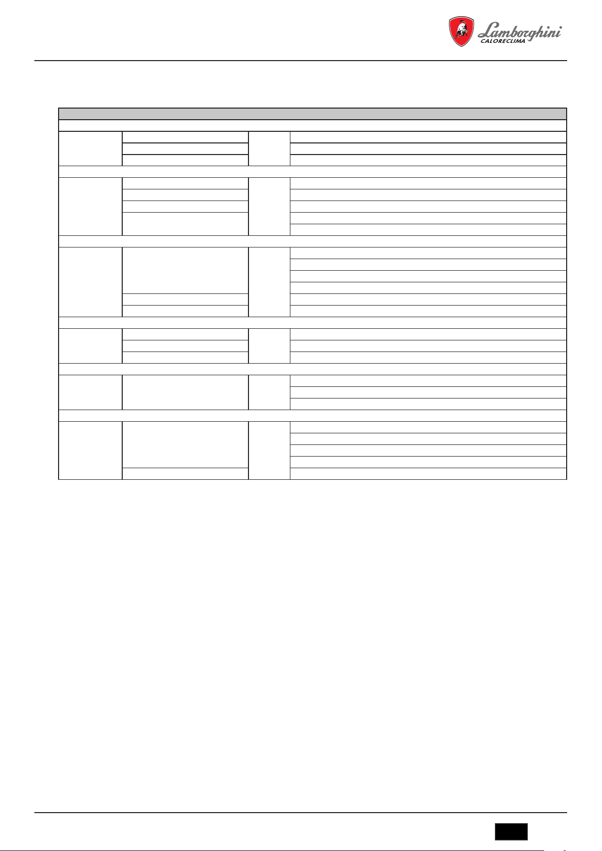
MEGAPREX N 720N ÷ 1060N
8.7 Troubleshooting
The following is a list of the main faults and problems that may occur during boiler operation, specifying possible causes and solutions.
FAULT
THE BOILER IS EASILY SOILED
CAUSE: Burner poorly adjusted SOLUTION: Check the burner adjustment (flue gas analysis)
Flue blocked Clean the flue gas path and the flue
Burner air intake path dirty Clean the burner air intake
THE BOILER DOES NOT REACH THE SET TEMPERATURE
CAUSE: Boiler body dirty SOLUTION: Clean the flue gas path
Boiler/burner combination Check the data and adjustments
Burner flow-rate insufficient Check the burner adjustment
Control thermostat Check correct operation
Check the set temperature
BOILER THERMAL SAFETY SHUTDOWN WITH INDICATOR LIGHT ON THE CONTROL PANEL
CAUSE: Control thermostat SOLUTION: Check correct operation
Check the set temperature
Check the electrical wiring
Check the probe bulbs
Lack of water Check the circuit pressure
Air present Check the vent valve
THE BOILER REACHES THE SET TEMPERATURE, BUT THE CENTRAL HEATING SYSTEM IS COLD
CAUSE: Air present in the system SOLUTION: Vent the system
Pump fault Reset the pump
Minimum thermostat (if featured) Check the set temperature
ODOR OF UNBURNED SUBSTANCES
CAUSE: Flue gas leaking into the environment SOLUTION: Check that the boiler body is clean
Check that the flue is clean
Check the tightness of the boiler and flue
FREQUENT ACTIVATION OF THE SAFETY VALVE
CAUSE: System circuit pressure SOLUTION: Check the fill pressure
Check the system circuit
Check the calibration
Check the set temperature
System expansion vessel Check
cod. 3541O220 - Rev. 00 - 03/2018
IT
61

MEGAPREX N 720N ÷ 1060N
1. PRESENTATION ......................................................................................................................................................................... 63
2. MISES EN GARDE GÉNÉRALES .............................................................................................................................................. 63
3. CERTIFICATION ......................................................................................................................................................................... 63
4. CARACTERISTIQUES TECHNIQUES, DE FABRICATION ET MESURES .............................................................................. 63
4.1 Description de l'appareil ............................................................................................................................................................................... 63
4.2 Principe de fonctionnement ......................................................................................................................................................................... 64
4.3 Caractéristiques techniques - Mesures - Connexions hydrauliques ............................................................................................................ 64
4.4 Identication ................................................................................................................................................................................................. 65
5. INSTALLATION .......................................................................................................................................................................... 65
5.1 Emballage .................................................................................................................................................................................................... 65
5.2 Manipulation ................................................................................................................................................................................................ 65
5.3 Local d'installation (Fig. 4) ........................................................................................................................................................................... 65
5.4 Évacuation des produits de combustion (Fig. 5) .......................................................................................................................................... 66
5.5 Branchements hydrauliques ........................................................................................................................................................................ 66
5.5.1 Eau d'alimentation .................................................................................................................................................................................. 66
5.5.2 Tuyauteries aller/retour de l'installation .................................................................................................................................................. 66
5.5.3 Tuyauteries de remplissage/vidange de l'installation ............................................................................................................................. 66
5.5.4 Tuyauteries du vase d'expansion et valve de sécurité ........................................................................................................................... 67
5.5.5 Pompe de recirculation (Fig. 6) .............................................................................................................................................................. 67
5.6 Réglage de la porte (Fig. 7) ......................................................................................................................................................................... 67
5.7 Montage du brûleur (Fig. 8) ......................................................................................................................................................................... 67
5.8 Connexion du tube de refroidissement au regard (Fig. 9) ........................................................................................................................... 68
5.9 Montage du revêtement des tableaux sur les modèles 720÷1060. Séquence (Fig. 10) .............................................................................. 68
6. TABLEAU DE COMMANDE (EN OPTION)................................................................................................................................ 68
6.1 Tableau de commande thermostatique BT 2 et 3 étapes de brûleur (Fig. 11) ............................................................................................. 68
6.1.1 Vue avant du tableau (Fig. 11) ............................................................................................................................................................... 69
6.1.2 Schéma de la réglette des connexions électriques ................................................................................................................................ 69
6.1.3 Schéma électrique pour le brûleur et la pompe monophasique ............................................................................................................. 70
6.2 Tableau de commande EBM (Efcient Boiler Management, Gestion efcace de la chaudière) (Fig. 12) ................................................... 73
6.2.1 Tableau (Fig. 12) .................................................................................................................................................................................... 73
6.2.2 Schémas électriques .............................................................................................................................................................................. 74
6.3 Remarques sur les connexions ................................................................................................................................................................... 78
7. MISE EN MARCHE ..................................................................................................................................................................... 78
7.1 Contrôles préliminaires ................................................................................................................................................................................ 78
7.2 Premier allumage ......................................................................................................................................................................................... 79
7.3 Extinction de la chaudière ............................................................................................................................................................................ 79
8. ENTRETIEN ................................................................................................................................................................................ 79
8.1 Normes générales ....................................................................................................................................................................................... 79
8.2 Entretien ordinaire ....................................................................................................................................................................................... 79
8.3 Entretien extraordinaire ............................................................................................................................................................................... 79
8.4 Nettoyage de la chaudière (Fig. 13) ............................................................................................................................................................ 80
8.5 Vérication du fonctionnement de la chaudière ........................................................................................................................................... 80
8.6 Contrôle du fonctionnement du brûleur ....................................................................................................................................................... 80
8.7 Pannes et solutions possibles ..................................................................................................................................................................... 81
62
IT
cod. 3541O220 - Rev. 00 - 03/2018

MEGAPREX N 720N ÷ 1060N
1. PRESENTATION
Cher client, nous vous remercions d'avoir choisi une chaudière MEGAPREX N. Ce manuel a été conçu pour vous informer, en incluant
des mises en garde et des conseils, sur l'installation, l'utilisation correcte et l'entretien de la chaudière.
Nous vous prions de le lire avec attention et de le conserver pour référence ultérieure. Dans votre propre intérêt, nous vous invitons à suivre et
à observer scrupuleusement les instructions fournies dans le présent manuel pour pouvoir pleinement profiter de ce produit de haute qualité.
Le non-respect et la non-observation des mentions indiquées dans ce manuel annulent toute responsabilité de l'entreprise fabricante ainsi que
la garantie.
2. MISES EN GARDE GÉNÉRALES
Le manuel d'instructions fait partie du produit et vous fournit une description de tous les points que vous devez observer dans la phase d'instal-
lation, utilisation et d'entretien.
- Cet appareil doit être destiné uniquement à l’utilisation pour laquelle il a été expressément prévu.
- Cet appareil sert à chauffer de l'eau à une température inférieure à la température d'ébullition à la pression atmosphérique. Il doit
être connecté à une installation de chauffage et/ou de distribution d'eau chaude à fins sanitaires, conformément à ses caractéristiques et prestations et selon la puissance calorifique.
- Avant l'installation, il faudra vérifier que la chaudière n'a souffert aucun dommage lié à la manipulation et au transport.
- L'installation doit être réalisée par du personnel qualifié de manière adéquate et selon les normes en vigueur.
- Avant de réaliser toute opération de nettoyage ou d'entretien, débranchez l'appareil du réseau d'alimentation électrique.
- LAMBORGHINI ne porte aucune responsabilité pour les dommages aux personnes et/ou aux objets suite à des erreurs d'installation, de
réglage, d'entretien et des utilisations incorrectes.
- La mise en marche de la chaudière et l'installation de celle-ci doit être réalisée par une personne agréée.
- La première mise en fonction a pour objectif de vérifier le bon fonctionnement de tous les dispositifs de réglage et de contrôle.
- La non-utilisation de l'appareil pendant une période prolongée nécessite l'intervention de personnel qualifié.
Ensemble de normes
L'installateur doit respecter la règlementation locale en vigueur pour ce qui concerne les points suivants : sélection du site d'installation de la
chaudière, respect des conditions de ventilation nécessaires, vérification que la connexion et la cheminée sont en parfait état, connexions du
combustible, des installations électriques et autres dispositions éventuelles en rapport avec la sécurité.
Conditions de garantie
La validité de la garantie est subordonnée à l'observation des normes et conseils d'utilisation dans le présent manuel. Tout non-respect ou
modification annulera sa validité. La garantie ne couvre pas les dommages causés par la corrosion des condensats d'acide des produits de
combustion ou suite à la formation d'incrustations dues à l'utilisation d'eaux dures ou agressives car seuls les dommages découlant de l'exploitation et de l'installation sont couverts.
3. CERTIFICATION
Le marquage <<CE>> atteste que les produits sont conformes aux exigences essentielles de l’ensemble des directives
qui leurs sont applicables.
La déclaration ce de conformité peut être demandée au fabricant.
CODES D’IDENTIFICATION DES PRODUITS
MEGAPREX N 720N 0QIJHBXD
MEGAPREX N 820N 0QIJIBXD
PAYS DE DESTINATION: IT - ES - RU
MEGAPREX N 940N 0QIJJBXD
MEGAPREX N 1060N 0QIJKBXD
4. CARACTERISTIQUES TECHNIQUES, DE FABRICATION ET MESURES
4.1 Description de l'appareil
Le type de fabrication des chaudières de la série MEGAPREX N garantit la puissance et des rendements élevés avec de faibles températures
des fumées, ceci permettant d'obtenir une faible émanation d'émissions polluantes. La fabrication suit la norme EN 303 Partie 1. Les principaux
éléments techniques de la conception sont les suivants :
- études soignées des formes afin d'obtenir une relation optimale entre les volumes de combustion et les surfaces d'échange ;
- sélection des matériaux utilisés pour une longue durée de vie de la chaudière.
Les chaudières ont une combustion sous pression, avec 2 étapes de fumées, de type cylindrique horizontal avec inversion de flamme dans le
foyer, complètement entouré d'eau de refroidissement. La flamme que produit le brûleur se retourne de préférence vers la partie antérieure où
les fumées entrent dans le faisceau de tubes où sont insérées les turbohélices qui créent des turbulences augmentant les échanges thermiques
par convexion. À la sortie du faisceau de tubes, les fumées sont récupérées dans la chambre avant et sont amenées à la cheminée.
cod. 3541O220 - Rev. 00 - 03/2018
IT
63

MEGAPREX N 720N ÷ 1060N
Les chaudières sont équipées d'une porte avec gond permettant une ouverture vers la droite ou la gauche et pouvant être régulée en hau-
teur et en profondeur. Le corps est isolé à l'aide d'une épaisse couche de laine de verre recouverte d'une cape supplémentaire de matériaux
empêchant les ruptures et fissures. Le fini externe est formé de panneaux en acier vernis.
Les chaudières sont équipées de 2 connexions de 1/2" pour les gaines porte-boules (peuvent respectivement accueillir 3 boules). Le tableau
de commande déjà précâblé sera mis en place sur la chaudière et permet son fonctionnement automatique.
4.2 Principe de fonctionnement
Les chaudières MEGAPREX N sont équipées d'un foyer aveugle cylindrique dans lequel la flamme du brûleur est renversée en
périphérie vers l'avant. Depuis celui-ci, les gaz de combustion entrent dans les tubes de fumée. En sortie, celles-ci sont récupérées dans la
chambre correspondante et sont alors amenées à la cheminée. Pendant le fonctionnement du brûleur, la chambre de combustion est toujours
sous pression. Pour connaître la valeur de cette pression, voir le Tableau 1, colonne Pertes de charge côté fumées. La conduite de fumées
et la connexion à la cheminée doivent être réalisées selon les normes et la législation en vigueur, avec des conduites rigides, résistantes à la
température, à l'eau de condensation, aux stress mécaniques et à l'étanchéité. (Fig. 1)
4.3 Caractéristiques techniques - Mesures - Connexions hydrauliques
MEGAPREX N 720N 820N 940N 1060N
Puissance nominale
Puissance de la chambre de combustion
Rendement utile à 100% de la puissance
maximale
Rendement utile à 30% de la puissance
maximale
Capacité totale de la chaudière Litres 735 735 850 1 250
Pertes de charge côté eau
Pertes de charge côté fumées mbar 4,5 5,6 5,4 6
Pression maximale de fonctionnement bar 6 6 6 6
Poids à sec kg 1 250 1 250 1 420 1 580
DIMENSIONS
ENTRÉE D'EAU CHAUDE T1 DN 100 DN 100 DN 100 DN 125
RETOUR D'EAU CHAUDE T2 DN 100 DN 100 DN 100 DN 125
CONNEXION AU RÉSERVOIR
D'EXPANSION
DÉCHARGE DE LA CHAUDIÈRE T4 1" 1" 1" 1"
SORTIE DES FUMÉES T5 Øe mm 340 340 340 400
min kW 468 533 611 667
max kW 720 820 940 1 000
min kW 502 566 651 717
MAX kW 777 881 1 011 1 075
% 92,71 93,10 92,95 93,05
% 93,60 94,40 94,20 96,75
mbar 32 40 51 65
mbar 18 25 25 33
mbar 10 18 16 20
A mm 1 250 1 250 1 250 1 430
B mm 1 784 1 784 2 024 2 028
C mm 1 335 1 335 1 335 1 515
D mm 162 162 162 162
E mm 212 212 212 240
F mm 219 219 219 214
G mm 830 830 830 900
H mm 565 565 565 670
I mm 2 215 2 215 2 455 2 482
L mm 196 196 196 196
L1 mm 227 227 227 227
M mm 1 400 1 400 1 400 1 580
N mm 223 223 223 227
O mm 440 440 480 480
P mm 700 700 900 900
Q mm 1 200 1 200 1 200 1 380
R mm 1 752 1 752 1 992 1 992
T3 2 1/2" 2 1/2" 2 1/2" 3"
64
IT
cod. 3541O220 - Rev. 00 - 03/2018

MEGAPREX N 720N ÷ 1060N
Légende (Fig. 2)
1 Tableau de commandes T2 Retour de chauffage
2 Plaque de support du brûleur T3 Connexion au vase d'expansion
3 Porte de nettoyage de la chambre des fumées T4 Vidange de la chaudière
4 Regard de contrôle de la flamme T5 Sortie de fumée
T1 Aller chauffage T6 Connexion du brûleur
4.4 Identication
La chaudière peut être identifiée à l'aide de (Fig. 3) :
- Enveloppe porte-documents
Celle-ci se trouve à l'intérieur du foyer de la chaudière, à côté du tableau porte-instruments :
- Manuel technique
- Certificat de garantie
- Plaque des caractéristiques
Vous trouverez sur la plaque des caractéristiques les données techniques et les prestations de l'appareil.
Elle se trouve sur le côté extérieur du tableau abritant les instruments.
Toute modification, enlèvement, manque de plaques d'identification ou tout élément empêchant l'identification sûre du produit entravent les
opérations d'installation et d'entretien.
5. INSTALLATION
5.1 Emballage
Les chaudières MEGAPREX N sont livrées avec les éléments suivants : porte, chambre de fumées et isolation installées. Les tableaux
se trouvent dans un emballage distinct en carton.
Le tableau des instruments, la protection en fibre céramique de la brique de brûleur se trouvent dans la chambre de combustion.
Le tableau des instruments est livré dans une boîte en carton se trouvant dans la chambre de combustion.
5.2 Manipulation
Les chaudières MEGAPREX N sont pourvues de crochets de levage. Manipulez les éléments avec précaution à l'aide d'instruments
adaptés à leur poids. Avant de connecter la chaudière, retirez la base en bois.
5.3 Local d'installation (Fig. 4)
Les chaudières MEGAPREX N devront être installées dans des locaux pour utilisation exclusive. Ceux-ci doivent répondre à la législa-
tion en vigueur et être pourvus d'ouvertures de ventilation aux dimensions adéquates. Les ouvertures de ventilation devront être permanentes
et communiquer directement avec l'extérieur. Elles devront être situées à un niveau en hauteur ainsi qu'en bas conformément avec l'ensemble
des normes en vigueur. L'emplacement des ouvertures de ventilation, les circuits d'alimentation du combustible, de distribution de l'énergie
électrique et de l'illumination devra respecter les dispositions légales en vigueur relatives au type de combustible employé. Pour faciliter le
nettoyage du circuit des fumées, il faudra laisser à l'arrière de la chaudière un espace libre de la même taille ou plus grand que le corps de la
chaudière. En aucun cas, celui-ci ne peut être inférieur à 1 300 mm. On vérifiera en outre que, avec la porte ouverte à 90º, la distance entre la
porte et le mur contigu (X), sera d'au moins égale à la longueur du brûleur.
La surface d'appui de la chaudière devra être totalement plane. Il est recommandé de prévoir un socle de ciment apte à supporter le poids total
de la chaudière, y compris le contenu d'eau. Pour les mesures du socle, reportez-vous aux côtes R x Q (tableau des mesures). Si le brûleur est
alimenté en gaz combustible d'un poids spécifique supérieur à celui de l'air, les pièces électriques devront être situées à une distance du sol
supérieure à 500 mm. Ces chaudières ne peuvent être installées à l'air libre car elles ne sont pas conçues pour fonctionner à l'extérieur et ne
disposent pas de système antigel automatique.
INTÉGRATION DANS DE VIEILLES INSTALLATIONS
Si la chaudière est placée dans de vieilles installations, vérifiez les points suivants :
- la cheminée doit être adaptée aux températures des produits de combustion. Il faut qu'elle soit prévue et construite selon l'ensemble de
normes en vigueur, qu'elle soit étanche, isolée et qu'aucune obstruction ne soit présente au niveau des rétrécissements.
- l'installation doit avoir été réalisée par du personnel qualifié et selon les normes en vigueur ;
- la ligne d'alimentation du combustible et le réservoir éventuellement présent ont été réalisés selon les normes en vigueur ;
- le ou les vase(s) d'expansion assurent l'absorption complète de la dilatation du fluide contenu dans l'installation ;
- le débit, la pression statique et la direction du flux des pompes de circulation sont adéquats ;
- l'installation est libre de boues, incrustations, l'air a été éliminé et l'étanchéité a été vérifiée ;
- un système de traitement de l'eau d'alimentation/réapprovisionnement a été prévu (voir les valeurs de référence).
cod. 3541O220 - Rev. 00 - 03/2018
IT
65

MEGAPREX N 720N ÷ 1060N
5.4 Évacuation des produits de combustion (Fig. 5)
La conduite de fumées et la connexion à la cheminée doivent être réalisées selon les normes et la législation en vigueur, avec des conduites
rigides, résistantes à la température, à l'eau de condensation, aux stress mécaniques et à l'étanchéité.
La cheminée doit assurer la pression négative minimum prévue par les normes en vigueur, en prenant comme référence la pression « zéro »
dans la connexion avec le conduit de fumées. La cheminée et les conduites de fumées inadaptées ou mal dimensionnées peuvent amplifier le
bruit de la combustion, créer des problèmes de condensation et influencer négativement les paramètres de combustion. Les conduits d'évacuation non isolés sont une source de dangers. L'étanchéité des connexions sera réalisée avec des matériaux résistant à des températures
d'au moins 250ºC. Dans la section de connexion entre la chaudière et la cheminée, il faudra prévoir des points de mesure de la température
des fumées et d'analyse des produits de la combustion.
Pour ce qui concerne la section et la hauteur de la cheminée, il faudra faire référence aux règlementations nationales et locales en vigueur.
5.5 Branchements hydrauliques
5.5.1 Eau d'alimentation
Les caractéristiques chimiques de l'eau de l'installation et de réapprovisionnement sont fondamentales pour le bon fonctionnement et la sécurité
de la chaudière. L'eau sera traitée avec les systèmes opportuns. Les valeurs de référence sont celles figurant dans le tableau suivant :
DURETÉ TOTALE ppm 10
ALCALINITÉ mg/l CaCO3 750
PH 8÷9
SILICE ppm 100
CHLORURES ppm 3 500
Il est absolument indispensable de traiter l'eau usée pour l'installation de chauffage dans les cas suivants :
- installations de grande taille ;
- eau très dure ;
- introductions fréquentes d'eau de réapprovisionnement dans l'installation.
Si le vide partiel ou total de l'installation s'avérait nécessaire, il est recommandé de réaliser le remplissage postérieur avec de l'eau traitée. Pour
le contrôle du volume des dispositifs de réapprovisionnement, il est conseillé d'installer un compteur sur la tuyauterie. Les phénomènes les plus
communs dans les installations thermiques sont les suivants :
- Incrustations de calcaire
Le calcaire se concentre sur les points où la température murale est la plus élevée. Les incrustations de calcaire, de par leur faible conductivité
thermique, réduisent l'échange thermique, même si leur épaisseur n'est que de quelques millimètres. Elles empêchent l'échange thermique
entre les fumées et l'eau, ce qui provoque une augmentation de la température des parties exposées aux flammes et les fissures résultantes
dans la plaque tubulaire.
- Corrosion côté eau
La corrosion des surfaces métalliques de la chaudière, côté eau, est due au transfert des ions fer à la solution. Lors de ce processus, la présence de graisses dissoutes et celles d'oxygène et de dioxyde de carbone, joue un grand rôle. Si l'on utilise des eaux adoucies et / ou déminéralisées, le phénomène d'incrustation ne se produira pas, ce qui n'est pas le cas des corrosions. Dans ce cas, il est nécessaire de traiter l'eau
avec des inhibiteurs des processus de corrosion.
5.5.2 Tuyauteries aller/retour de l'installation
Les dimensions des tuyauteries d'aller et de retour sont indiquées pour chacun des modèles de chaudière dans le tableau MESURES. Assurezvous que l'installation comporte un nombre suffisant de dispositifs de purge.
Les connexions de la chaudière ne doivent pas supporter le poids des tuyauteries de connexion à l'installation. Ceci implique l'installation de
supports adéquats.
5.5.3 Tuyauteries de remplissage/vidange de l'installation
Pour remplir et vidanger la chaudière, on peut connecter un robinet à la connexion T4 située sur la partie postérieure (voir le dessin MESURES
Fig. 2).
66
IT
cod. 3541O220 - Rev. 00 - 03/2018
MEGAPREX N 720N ÷ 1060N
5.5.4 Tuyauteries du vase d'expansion et valve de sécurité
Les chaudières MEGAPREX N sont aptes pour un fonctionnement avec circulation d'eau forcée avec un vase d'expansion ouvert ou fer-
mé. Un vase d'expansion est toujours nécessaire pour compenser l'augmentation du volume d'eau suite au chauffage. Dans le premier cas, la
hauteur de la colonne hydrostatique devra au moins être de 3 mètres au-dessus du corps de la chaudière et devra avoir une capacité suffisante
pour contenir, entre la surface de l'eau, le vase et le tube du déversoir, l'augmentation du volume de toute l'eau de l'installation. Les vases hauts
et étroits sont conseillés car ceci permet d'exposer au contact de l'air la plus faible surface d'eau possible, ce qui réduit l'évaporation. Dans le
deuxième cas, la capacité du vase d'expansion fermé doit se calculer en prenant en compte les points suivants :
- volume total de l'eau de l'installation ;
- pression maximale de fonctionnement de l'installation ;
- pression maximale de fonctionnement du vase d'expansion ;
- pression de recharge initiale du vase d'expansion ;
- température maximale de fonctionnement de la chaudière (la température maximale du thermostat monté sur le tableau et de 90ºC, mais
pour réaliser ce calcul, nous recommandons d'utiliser une valeur de 100ºC).
La tuyauterie d'expansion connecte le vase d'expansion avec l'installation. Cette tuyauterie qui partira de la connexion T3 (voir le tableau
Mesures) ne devra pas inclure de vanne de coupure. Installez sur la connexion T3 ou dans la tuyauterie de décharge à 0,5 m de la bride de
sortie, une soupape de sécurité adaptée à la capacité de la chaudière et conforme aux normes locales en vigueur. Il est interdit d'installer un
dispositif d'interception entre la chaudière et les soupapes de sécurité. Nous recommandons que ces soupapes soient réglées pour provoquer
leur fonctionnement si la pression maximale de fonctionnement autorisée.
5.5.5 Pompe de recirculation (Fig. 6)
La condensation de la vapeur d'eau contenue dans les fumées d'évacuation de la chaudière (eau de condensation) a lieu lorsque la températu-
re de l'eau de retour est inférieure à 50ºC. Elle est surtout importante lors de l'allumage matinal après la nuit où la chaudière a été complètement
éteinte. L'eau de condensation est acide et corrosive. Elle attaque progressivement les tôles de la chaudière. Il est donc recommandé de mettre
en place une pompe de recirculation qui a une fonction de lutte contre la condensation. Elle est installée entre les connexions aller et retour,
avant la vanne de mélange, le cas échéant. La pompe doit assurer un débit situé entre 20 et 30% du total pendant les périodes de fonctionnement de l'installation. La pompe de recirculation (anti-condensats) est commandée à l'aide du tableau de thermostat de basse température (en
option). La boule du thermostat correspondant doit être placée dans le retour (à l'aide d'une gaine que l'installateur doit monter sur la conduite
en question).
5.6 Réglage de la porte (Fig. 7)
Sur toutes les chaudières pressurisées, il est possible de régler et d'inverser le sens d'ouverture de la porte.
Ouverture
Pour fixer le côté de la porte, il suffit de serrer les contre-écrous 2 et 4 contre les écrous 1 et 3.
Pour inverser le sens d'ouverture, serrez les contre-écrous 2 et 4 du côté opposé.
Fermeture
Desserrez les contre-écrous 2 et 4 contre et serrez suffisamment les écrous 1 et 3 avant de resserrer les contre-écrous 2 et 4.
Mise en place
Après avoir monté le brûleur, il est nécessaire de positionner la porte. Ceci est possible en desserrant les écrous 1 et 3, le goujon prisonnier 5
et en réglant la hauteur à l'aide de l'écrou 6. Ceci devra se faire de façon à ce que l'ensemble du cordon de serrage exerce une pression sur la
tôle en serrant les écrous 1 et 3.
5.7 Montage du brûleur (Fig. 8)
Le montage du brûleur sur la porte de la chaudière doit garantir une étanchéité parfaite aux produits de la combustion. Une fois installé le
brûleur sur la chaudière, il faudra remplir l'espace entre la brique de brûleur et le matériau réfractaire de la porte avec les rondelles en fibre
céramique (A) fournies. Cette opération évite la surchauffe de la porte qui se déformerait sinon de façon irrécupérable. Les connexions entre
le combustible et le brûleur doivent être placées de façon à permettre l'ouverture totale de la porte de la chaudière avec le brûleur installé.
Nous vous conseillons de placer un pied d'appui rigide sous le brûleur afin d'éviter que tout son poids influe négativement sur la porte.
RSW L min. (mm) L max. (mm) S
720-1060 N 320 390 239
cod. 3541O220 - Rev. 00 - 03/2018
IT
67

MEGAPREX N 720N ÷ 1060N
5.8 Connexion du tube de refroidissement au regard (Fig. 9)
Le regard de contrôle de la flamme est équipé d'une prise de pression 1 qui doit être connectée une fois desserrée la vis intérieure, à l'aide d'un
tube de silicone ou de cuivre, à la prise située sur le brûleur 2. Cette opération permett que l'air soufflé par le ventilateur refroidisse le verre du
regard, empêchant ainsi qu'il ne noircisse. La non-connexion du tube au regard peut entraîner la rupture du verre.
Si le regard est démonté pour le nettoyer, assurez-vous que les joints sont en bon état et remplacez-les si nécessaire et vérifiez l'étanchéité
après fermeture.
5.9 Montage du revêtement des tableaux sur les modèles 720÷1060. Séquence (Fig. 10)
a) Placez soigneusement les panneaux latéraux (rep. 1 et 2 - 3 et 4) et suspendez-les sur les supports de la chaudière.
b) Montez le U (repère 12).
c) Fixez le tableau des commandes sur le panneau supérieur avant (repère 5).
d) Appuyez le panneau supérieur (rep. 5) incluant le tableau des commandes, sur le panneau latéral (rep. 1) incluant les ressorts, les pivots et
les écrous (rep. 9-10-11).
e) Insérez les boules des instruments dans les gaines (rep. 13) et réalisez la connexion électrique du tableau des commandes sur la ligne
d'alimentation, au brûleur et aux éventuelles pompes, etc. Nous vous recommandons d'insérer les sondes jusqu'au fond des gaines correspondantes pour améliorer le contact. Bloquez ensuite les capillaires avec les ressorts. Refermez le couvercle du tableau électrique et passez la
prise du brûleur au travers des orifices de la plaque avant (rep. 14).
d) Montez les panneaux supérieurs (rep. 6-7-8) sur les panneaux latéraux (rep.2-3-4) incluant les ressorts, les pivots et les écrous (rep. 9-10-
11).
g) Montez le panneau avant (rep. 15) sur la porte avant à l'aide des vis (rep. 16) et les écrous (rep. 17). Le panneau doit être monté avant
d'installer le brûleur.
6. TABLEAU DE COMMANDE (EN OPTION)
C16015180 – Tableau de commande thermostatique BT 2 étapes
C16015190 – Tableau de commande thermostatique BT 3 étapes
C16015150 – Tableau de commande EBM (Efficient Boiler Management, Gestion efficace de la chaudière)
6.1 Tableau de commande thermostatique BT 2 et 3 étapes de brûleur (Fig. 11)
(Les schémas apparaissant ci-après sont valables pour les trois tableaux.)
Tableau non alimenté, en plastique d'un niveau de protection IP40, accueillant les instruments de réglage et de sécurité. Les tableaux BT
incluent un signal de thermostat pour la commande de la bombe anti-condensats, comme indiqué au paragraphe 5.5.5. L'installation de la
chaudière doit être :
- conçue et mise en œuvre par un personnel qualifié et connectée à une installation de prise de terre, conformément aux normes légales en
vigueur ;
- adaptée à la puissance maximale absorbée par la chaudière avec des câbles électriques d'une section correspondante.
Les câbles d'alimentation et de connexion au brûleur doivent inclure un conducteur à la terre mesurant quelques millimètres de plus que les
autres conducteurs du même câble. Pour les connexions entre le brûleur, le tableau électrique et l'alimentation électrique, nous recommandons
l'utilisation du câble H07 RN-F pour les connexions avec installation visible. Pour les autres types d'installation ou pour les conditions d'environnement spéciales, nous vous recommandons de consulter les normes applicables. La formation et le diamètre des conducteurs sont calculés
en fonction de la puissance absorbée par le brûleur. Pour accéder aux instruments, tournez le panneau avant (A). Pour accéder aux terminaux
de connexion et pour étendre les capillaires des thermostats et du thermomètre, retirez le panneau supérieur (B). Pour ce faire, démontez auparavant les 2 vis latérales (C). Les thermostats de réglage (12-13 - Fig. 12) peuvent être réglés par l'utilisateur à l'aide de la poignée centrale.
Le thermostat de sécurité a un réglage fixe ; il est réarmé manuellement. Vous devez obligatoirement :
- utiliser un interrupteur magnétothermique bipolaire, un disjoncteur d'alimentation, conformément aux normes CEI-EN (ouverture des contacts d'environ 3 mm minimum) ;
- respecter la connexion L1 (phase) - N (neutre) ;
- utiliser des câbles d'une section supérieure ou égale à 1,5 mm² incluant des terminaux ;
- vous référer aux schémas électriques de ce manuel d'instructions pour toute intervention sur le système électrique ;
- réaliser une connexion efficace à la terre ;
- respecter l'interdiction d'utilisation des tubes d'eau pour la mise à la terre de l'appareil.
Le fabricant n'est pas responsable des éventuels dommages causés par l'absence de mise à la terre de l'appareil et par le non-respect des
indications des schémas électriques.
68
IT
cod. 3541O220 - Rev. 00 - 03/2018

MEGAPREX N 720N ÷ 1060N
6.1.1 Vue avant du tableau (Fig. 11)
Légende
1
Interrupteur d'allumage de la pompe de l'installation8Pilote LED 1
2
Interrupteur d'allumage du brûleur
3
Interrupteur d'allumage de la chaudière
4
Bouton de test
5
Bouton de rétablissement du pressostat de sécurité12Thermostat TR1 réglage 2
6
Température de l'eau de la chaudière
7
Pilote LED de chaudière connectée
6.1.2 Schéma de la réglette des connexions électriques
ère
étape du brûleur
9
Pilote LED 2
10
Pilote LED du bloc de brûleur
11
Pilote LED du pressostat de sécurité
13
Thermostat TR1 réglage 1
14
Emplacement prévu pour la centrale de thermorégulation
ème
étape du brûleur
ème
étape
ère
étape
(*) Uniquement tableaux BT
(**) Uniquement tableaux BT 3 étapes
L
N 14
Alimentation du tableau des commandes
3
Alimentation du brûleur
4 17
5
Thermostat 1
6 19
Thermostat 1
8 21
ère
phase
ère
phase
9 Pilote de blocage 22
10 Pilote de fonctionnement 2
11
Alimentation de la pompe de l'installation
12
ème
phase 23
cod. 3541O220 - Rev. 00 - 03/2018
13
Allumage de la chaudière à distance
(si présent, sinon pont)
15
Sécurité de la chaudière à distance
(si présent, sinon pont)
16
Thermostat d'ambiance
18
20
Signal pour pompe anti-condensats7
ème
Thermostat 3
phase
IT
69

MEGAPREX N 720N ÷ 1060N
6.1.3 Schéma électrique pour le brûleur et la pompe monophasique
Schéma électrique
1 - (S1) Autorisation d'allumage distant
2 - (TS1) Thermostat de sécurité de la chaudière
3 - (S2) Autorisation externe de sécurité
4 - (TR1) Thermostat 1
5 - (SA2) Interrupteur d'allumage du brûleur
6 - (N1) Thermomètre numérique
7 - (B1) Thermorésistance de l'eau de la chaudière
8 - (SB1) Bouton de test du thermostat
9 - (TR2) Thermostat 2
10 - (TR2) Thermostat 3
UNIQUEMENT POUR LE TABLEAU 3
FLAMME
11 - (XT1) Contact de la gestion de la pompe anti-
condensats
UNIQUEMENT POUR LE TABLEAU DE
BASSE TEMPÉRATURE
12 - (S3) Thermostat d'ambiance
13 - (TR3) Thermostat
14 - (SA3) Interrupteur d'allumage du circulateur
15 - (P1) Pompe de circulation de l'eau
16 - (SA1) Interrupteur d'allumage de la chaudière
17 CONNEXIONS DU BRÛLEUR
17 - (17/a) Bloc de brûleur
17 - (17/b) Deuxième flamme
17 - (17/c) Autorisation de la 1
17 - (17/d) Autorisation de la 2
17 - (17/e) Alimentation du brûleur
17 - (17/f) Autorisation de la 3
ère
flamme de la chaudière
ème
flamme de la chaudière
ème
flamme de la chaudière
ère
flamme
ème
flamme
ème
flamme
ème
70
IT
cod. 3541O220 - Rev. 00 - 03/2018

MEGAPREX N 720N ÷ 1060N
Schéma de connexion
cod. 3541O220 - Rev. 00 - 03/2018
IT
71

Réglettes
Courant maximal
absorbé 3 ampères
IIIIIIIIIII
MEGAPREX N 720N ÷ 1060N
Courant maximal
absorbé 3 ampères
IIIII
Réaliser un pont s'il n'est pas présent
I
III
Réaliser un pont s'il n'est pas présent
III
Réaliser un pont s'il n'est pas présent
III
UNIQUEMENT POUR LE TABLEAU DE BASSE
TEMPÉRATURE
IIIII
IIIII
amme
ère
Alimentation 230 VCA 50-60Hz monophasé (phase)
Alimentation 230 VCA 50-60Hz monophasé (neutre)
Alimentation 230 VCA 50-60Hz monophasé (connecter à la terre)
Alimentation du brûleur 230 VCA 50-60Hz monophasé (terre)
Alimentation du brûleur 230 VCA 50-60Hz monophasé (phase)
Alimentation du brûleur 230 VCA 50-60Hz monophasé (neutre)
Signal de fonctionnement du brûleur 1
amme
amme
amme
ère
ème
ème
Signal de fonctionnement du brûleur 2
Signal de blocage du brûleur
Signal de fonctionnement du brûleur 1
Signal de fonctionnement du brûleur 2
Signal de blocage du brûleur
Alimentation de la pompe de l'installation 230 VCA 50-60Hz monophasé (terre)
Alimentation de la pompe de l'installation 230 VCA 50-60Hz monophasé (phase)
Alimentation de la pompe de l'installation 230 VCA 50-60Hz monophasé (neutre)
Signal d'allumage de la chaudière à distance
Signal d'allumage de la chaudière à distance
Signal de sécurité de la chaudière extérieur
Signal de sécurité de la chaudière extérieur
Thermostat d'ambiance
Thermostat d'ambiance
amme brûleur [ Com ]
amme brûleur [ NO ]
amme brûleur [ NF ]
ème
ème
ème
/ 3
/ 3
/ 3
ème
ème
ème
Signal de pompe anti-condensats chaudière [ Com ]
Signal de pompe anti-condensats chaudière [ NO ]
Signal de pompe anti-condensats chaudière [ NF ]
Thermostat 2
Thermostat 2
Thermostat 2
72
IT
cod. 3541O220 - Rev. 00 - 03/2018

MEGAPREX N 720N ÷ 1060N
IT
Temperatura mandata acqua caldaia
Interruttore bruciatore
IT
Interruttore bruciatore
IT
Temperatura mandata acqua caldaia
Strumento stato caldaia/Temperatura acqua
Interruttore bruciatore
Interruttore circolatore
IT
Interruttore bruciatore
IT
Temperatura mandata acqua caldaia
Strumento stato caldaia/Temperatura acqua
Circolatore acqua impianto
Interruttore bruciatore
Interruttore circolatore
Pulsante test
IT
Interruttore bruciatore
Interruttore circolatore
Pulsante test
IT
Temperatura mandata acqua caldaia
Strumento stato caldaia/Temperatura acqua
Circolatore acqua impianto
Consenso accensione remoto
Interruttore bruciatore
Interruttore circolatore
Pulsante test
Termostato 1° stadio bruciatore
IT
Interruttore bruciatore
Interruttore circolatore
Pulsante test
Termostato 1° stadio bruciatore
IT
Temperatura mandata acqua caldaia
Strumento stato caldaia/Temperatura acqua
Circolatore acqua impianto
Consenso accensione remoto
Interruttore bruciatore
Interruttore circolatore
Pulsante test
Termostato 1° stadio bruciatore
IT
Interruttore bruciatore
Interruttore circolatore
Pulsante test
Termostato 1° stadio bruciatore
Termostato 2° stadio bruciatore
Termostato di sicurezza caldaia
IT
Temperatura mandata acqua caldaia
Strumento stato caldaia/Temperatura acqua
Circolatore acqua impianto
Consenso accensione remoto
Consenso di sicurezza esterno
Termostato ambiente
Interruttore accensione caldaia
Interruttore bruciatore
Interruttore circolatore
Pulsante test
Termostato 1° stadio bruciatore
Termostato 2° stadio bruciatore
Termostato di sicurezza caldaia
Légende des symboles/composants du schéma électrique
B1
QG2Température de décharge de l'eau
N1
Instrument d'état de la chaudière/température de
QG
l'eau
2
P1
QG2Circulateur de l'eau de l'installation
S1
QG2Autorisation d'allumage distant
S2
QG2Autorisation externe de sécurité
S3
QG2Thermostat d'ambiance
SA1
QG2Interrupteur d'allumage de la chaudière
SA2
QG2Interrupteur du brûleur
SA3
QG2Interrupteur du circulateur
SB1
QG2Bouton de test
TR1
QG2Thermostat 1
TR2
QG2Thermostat 2
TS1
QG2Thermostat de sécurité de la chaudière
ère
phase du brûleur
ème
ème
/ 3
phase du brûleur
6.2 Tableau de commande EBM (Efcient Boiler Management, Gestion efcace de la chaudière) (Fig. 12)
C16015150 – Tableau de commande EBM (Efficient Boiler Management, Gestion efficace de la chaudière)
6.2.1 Tableau (Fig. 12)
Le tableau de commande EBM n'est pas fourni en série avec la chaudière. Il permet, entre autres, de réaliser les fonctions suivantes :
- sélection de la langue d'utilisation ;
- sélection du mode de fonctionnement : chauffage, fonctionnement économique et programmation horaire et vacances ;
- commande de la pompe de la chaudière ;
- commande de la pompe de bypass anti-condensats ;
- commande du brûleur une étape ;
- commande du brûleur deux étapes ;
- commande du brûleur modulateur ;
- compte des étapes du brûleur ;
- visualisation des paramètres de la chaudière ;
- visualisation des alarmes émises ;
- fonction climatique (avec sonde extérieure en option).
Il est possible de contrôler une installation avec une configuration maximale de :
- une zone de haute température pour la commande de la pompe ;
- une ou deux zones de basse température avec vanne de mélange et pompe ;
- un ballon d'eau chaude sanitaire, commande pompe selon la température du ballon.
Autres applications :
il peut être utilisé pour la connexion en cascade de jusqu'à 16 chaudières, système maître-esclave. Il peut être intégré à une installation solaire.
cod. 3541O220 - Rev. 00 - 03/2018
IT
73

6.2.2 Schémas électriques
Schéma électrique
MEGAPREX N 720N ÷ 1060N
1 - (2TS1) Thermostat de sécurité chaudière
2 - (2XT1)
3 - (2BU1) RACCORDEMENTS DU BRÛLEUR
3 - (2BU1) - A Blocage brûleur
3 - (2BU1) - B Autorisation 1
3 - (2BU1) - C Alimentation brûleur MAX. 3A
Signalisation pour appareils extérieurs
Signal 230 Vca intervention du thermostat
de sécurité chaudière
ère
flamme
74
IT
cod. 3541O220 - Rev. 00 - 03/2018

MEGAPREX N 720N ÷ 1060N
Schéma de connexion de l'unité de base de commande (1
ère
partie)
1 - (3P2) Pompe de dérivation (bypass)
2 - (3P1) Pompe de circulation d’eau
3 - (3B1) Capteur de température retour d’eau
4 - (3B1) Capteur de température d’ambiance
anti-condensation chaudière
Max. 2 A
À utiliser éventuellement comme
autorisation
Max. 2 A
À utiliser éventuellement comme
autorisation
chaudière
OPTIONS
Utiliser une sonde NTC 10K
extérieure
OPTIONS
Utiliser une sonde NTC 10K
cod. 3541O220 - Rev. 00 - 03/2018
IT
75
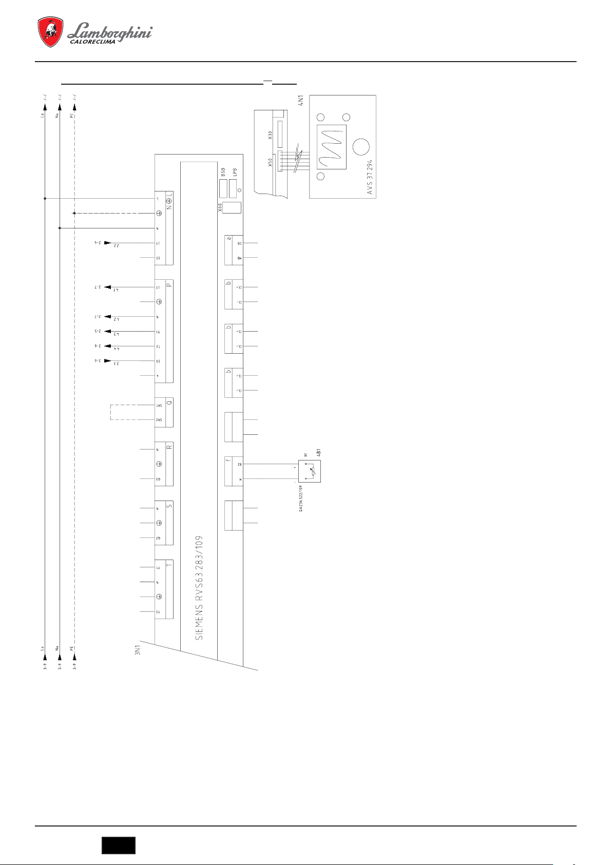
MEGAPREX N 720N ÷ 1060N
Schéma de connexion de l'unité de base de commande (2
ème
partie)
1 SAFETY-LOOP
Réaliser un pontage en l’absence
d’une autre autorisation de sécurité de
l’installation
2 - (4B1) Capteur de température départ d’eau
chaudière
Utiliser une sonde NTC 10K
3 - (4N1) Panneau unité opérateur
AVS 37.294
76
IT
cod. 3541O220 - Rev. 00 - 03/2018

MEGAPREX N 720N ÷ 1060N
Schéma des bornes de connexion du tableau
QG - M
Réglette générale
Alimentation 230 VCA 50-60Hz monophasé (phase)
Alimentation 230 VCA 50-60Hz monophasé (neutre)
Alimentation 230 VCA 50-60Hz monophasé (connecter à la terre)
BM - 2BU1 - Alimentation du brûleur 230 VCA 50-60Hz monophasé (terre)
BM - 2BU1 - Alimentation du brûleur 230 VCA 50-60Hz monophasé (phase)
BM - 2BU1 - Alimentation du brûleur 230 VCA 50-60Hz monophasé (neutre)
BM - 2BU1 - Signal 1
BM - 2BU1 - Signal 1
BM - 2BU1 - Signal de blocage du brûleur
BM - 2XT1 - Signal 230 VCA thermostat de sécurité de la chaudière
BM - 2XT1 - Signal 230 VCA thermostat de sécurité de la chaudière
Schéma des bornes de connexion de l'unité de base de commande
QG
Borne RVS63.283
BM - Signal de sécurité de l'installation
BM - Signal de sécurité de l'installation
BM - 3P1 - Pompe d'eau de la chaudière (230 VCA - Phase)
BM - 3P1 - Pompe d'eau de la chaudière (230 VCA - Terre)
BM - 3P1 - Pompe d'eau de la chaudière (230 VCA - Neutre)
BM - 3P2 - Pompe de bypass anti-condensats (230 VCA - Phase)
BM - 3P2 - Pompe d'eau de la chaudière (230 VCA - Terre)
BM - 3P2 - Pompe de bypass anti-condensats (230 VCA - Neutre)
ère
amme brûleur
ère
amme brûleur
I
I
Courant maximal
I
I
absorbé 3 ampères
I
I
I
I
I
I
I
Réaliser un pont si pas
I
nécessaire
I
I
I
MAX. 2A
I
I
I
I
I
I
I
MAX. 2A
I
I
BM - 4B1 - Sonde de température de la chaudière
BM - 4B1 - Sonde de température de la chaudière
BM - 3B3 - Sonde extérieure
BM - 3B3 - Sonde extérieure
I
I
EN OPTION
I
BM - 3B1 - Sonde de température de retour de la chaudière
BM - 3B1 - Sonde de température de retour de la chaudière
cod. 3541O220 - Rev. 00 - 03/2018
IT
77

Légende des symboles/composants du schéma électrique
MEGAPREX N 720N ÷ 1060N
2BU1
BM2Brûleur de chaudière
2HL1
QG2Lampe d'alimentation 230 VCA tableau
2HL2
Lampe d'alarme d'intervention thermostat de
QG
sécurité
2
2SB1
Interrupteur général d'allumage de la
QG
chaudière
2
2SB2
QG2Interrupteur d'allumage du brûleur
2TS1
QG2Thermostat de sécurité de la chaudière
2XT1
Signal 230 VCA intervention thermostat de
BM
sécurité
2
3B1
Sonde de température du retour de la
BM
chaudière
3
3B3
BM3Sonde extérieure
3N1
Unité de base de la commande MASTER
QG
(RSV 63 283/109)
3
3P1
BM3Pompe de l'installation
3P2
BM3Pompe de bypass anti-condensats
4B1
Capteur de température de l'eau de la
BM
chaudière
4
4N1
QG4Interface utilisateur Siemens AVS37.294
6.3 Remarques sur les connexions
Le câble d'alimentation du tableau de type FG7 RN-F 3G1,5 est déjà connecté de série au boîtier de connexions. En cas de remplacement,
utilisez un câble adapté conformément aux normes en vigueur. L'alimentation du brûleur provient directement du boîtier de connexions s'il s'agit
du type monophasé avec une intensité maximale de 3 A. L'alimentation du circulateur de l'eau de l'installation provient directement du boîtier de
connexions s'il s'agit du type monophasé avec une intensité maximale de 3 A. Si le brûleur ou la pompe ont une intensité supérieure à ce que
nous avons prévu ou bien s'il s'agit d'une alimentation triphasée, il sera nécessaire d'employer des relais de puissance connectés avec interface
avec les sorties prévues dans le boîtier des connexions.
L'autorisation d'allumage distant offre la possibilité d'allumer la chaudière à distance. On effectue un pont si elle n'est pas utilisée. L'autorisation
de sécurité externe de la chaudière permet d'insérer un contact postérieur provoquant l'extinction du brûleur. On effectue un pont si elle n'est
pas utilisée. Le contact du thermostat ambiant n'agit que sur le circulateur d'eau. On effectue un pont s'il n'est pas utilisé.
7. MISE EN MARCHE
7.1 Contrôles préliminaires
Une fois réalisées les connexions hydrauliques, électriques et du combustible à la chaudière, on vérifiera les points suivants avant la mise en
marche :
- le vase d'expansion et la soupape de sécurité sont correctement connectés et ne peuvent être absolument pas interceptés ;
- les boules des thermostats de réglage, de sécurité des valeurs minimales et du thermomètre sont introduites dans les gaines respectives ;
- les turbohélices sont situées dans tous les tubes de fumées ;
- l'installation est pleine d'eau et ne contient absolument pas d'air ;
- la ou les pompe(s) fonctionne(nt) correctement ;
- les connexions hydrauliques, électriques et de sécurité nécessaires ainsi que celle du combustible ont été réalisées conformément aux
dispositions nationales et locales en vigueur ;
- le brûleur a été monté selon les instructions figurant dans le manuel du fabricant ;
- la tension et la fréquence du réseau sont compatibles avec le brûleur et le système électrique de la chaudière ;
- l'installation est capable d'absorber la quantité de chaleur produite ;
- la pompe de recirculation est installée comme décrit dans le paragraphe 5.5.5.
78
IT
cod. 3541O220 - Rev. 00 - 03/2018

MEGAPREX N 720N ÷ 1060N
7.2 Premier allumage
Une fois effectuées ces vérifications avec succès, on pourra procéder au premier allumage du brûleur. Cette opération devra être réalisée par
un technicien agréé par l'entreprise ayant fabriqué le brûleur. Le technicien accepte toute la responsabilité pour tout ce qui touche au réglage
dans la plage de puissance déclarée et homologuée de la chaudière. Une fois ouverts les robinets de coupure de combustible et contrôlée
l'absence de perte au sein du réseau d'alimentation, mettez tous les interrupteurs en position ON (Marche). Le brûleur est ainsi préparé pour le
premier allumage et pour le réglage. Seul le technicien agréé doit se charger de cette opération.
Pendant le premier allumage, on devra vérifier que la porte, la bride du brûleur et les connexions avec la cheminée sont bien étanches et que la
base de la cheminée a une légère pression négative. Le débit de combustible devra correspondre aux données de la fiche de la chaudière. Il ne
devra dans aucun cas être supérieur à la valeur maximale de puissance déclarée. La température des fumées ne devra jamais être inférieure
à 160ºC.
7.3 Extinction de la chaudière
- Réglez le thermostat de fonctionnement au minimum.
- Débranchez la tension du brûleur et fermez l'alimentation du combustible.
- Laissez fonctionner les pompes jusqu'à ce que le thermostat de valeurs minimales les ferme.
- Débranchez la tension du tableau électrique.
8. ENTRETIEN
8.1 Normes générales
L'entretien périodique est essentiel pour la sécurité, le rendement et la durée de l'appareil.
Toutes les opérations doivent être réalisées par du personnel qualifié. Toutes les opérations de nettoyage et d'entretien devront être précédées
de la fermeture de l'alimentation en combustible, une fois la tension électrique débranchée.
Afin d'obtenir un bon fonctionnement et le rendement maximal de la chaudière, il est nécessaire de procéder à un nettoyage régulier de la
chambre de combustion des tubes de fumées et de la chambre de combustion.
8.2 Entretien ordinaire
L'entretien doit être établi en prenant en compte le combustible utilisé, le nombre d'allumages, les caractéristiques de l'installation, etc. Il n'est
donc pas possible d'établir a priori un intervalle de temps entre deux opérations successives d'entretien.
Nous conseillons d'établir en règle générale, les intervalles de nettoyage suivant, en fonction du combustible :
- Chaudières à gaz : une fois par an
- Chaudières à gasoil : deux fois par an
Quoi qu'il en soit, on veillera au respect des normes locales pouvant exister en rapport avec l'entretien.
Pendant les opérations d'entretien ordinaire, après avoir retiré les turbohélices, on procèdera au nettoyage du faisceau de tubes et du foyer à
l'aide de l'écouvillon. Retirez les dépôts accumulés dans la chambre de fumées depuis l'ouverture des portes d'inspection. Si l'entretien néces-
site l'application d'une force plus extensive, il faudra retirer la chambre de fumées située à l'arrière et remplacer le joint d'étanchéité des fumées
s'il est détérioré. Contrôlez que l'évacuation de l'eau de condensation n'est pas obstruée. On vérifiera le bon fonctionnement des organes de
commande et de mesure du générateur.
Ce faisant, on contrôlera la quantité d'eau de réapprovisionnement utilisée une fois l'analyse de l'eau effectuée et l'on procèdera à une désincrustation préventive.
Les sels de calcium et de magnésium dissous dans l'eau courante sont à l'origine de dépôts dans la chaudière après un certain nombre de
remplissages. Ils provoquent la surchauffe des tôles ce qui peut entraîner des dommages ne pouvant pas être attribués aux matériaux ou à la
technique de fabrication ce qui signifie qu'ils ne seront pas couverts par la garantie. Après avoir effectué les opérations d'entretien et de net-
toyage et après avoir rallumé la chaudière, vérifiez l'étanchéité de la porte et de la chambre de fumées. Si vous détectez des fuites de produit
de la combustion, remplacez le joint d'étanchéité correspondant.
Les opérations réalisées seront notées dans le cahier de la centrale.
8.3 Entretien extraordinaire
Entretien extraordinaire de fin de saison ou avant une longue période d'inactivité.
Celui-ci inclut toutes les opérations décrites dans le chapitre précédent et les points suivants :
- Contrôle de l'état d'usure des turbohélices.
- Après nettoyage du circuit de fumées, il est recommandé de passer un chiffon imbibé d'une solution de soude caustique. Après séchage,
passez un chiffon imbibé d'huile sur toutes les surfaces.
- Il est recommandé de placer dans le foyer des substances hygroscopiques (chaux vive, gel de silicone dans de petits containers) et de fer-
mer hermétiquement le foyer de façon à empêcher toute pénétration d'air.
- Ne videz pas l'installation ou la chaudière.
- Protégez les vis, les écrous et les boulons de la porte avec un mélange d'huile et de graphite.
Les opérations réalisées seront notées dans le cahier des opérations d'entretien.
cod. 3541O220 - Rev. 00 - 03/2018
IT
79

MEGAPREX N 720N ÷ 1060N
8.4 Nettoyage de la chaudière (Fig. 13)
Pour réaliser le nettoyage, procédez de la façon suivante :
- La chaudière est fournie avec une brosse de nettoyage des tubes de fumées.
- Ouvrez la porte avant (1) et extrayez les turbohélices (2).
- Nettoyez les surfaces internes de la chambre de combustion et du parcours des fumées à l'aide d'un écouvillon (3) ou tout autre ustensile
adapté.
- Retirez les dépôts accumulés dans la chambre de fumées depuis l'ouverture du couvercle de nettoyage (4). Si l'entretien nécessite l'appli-
cation d'une force plus extensive, il faudra retirer la chambre de fumées (5) et remplacer le joint d'étanchéité des fumées avant de procéder
au montage.
- Contrôlez périodiquement que l'évacuation de l'eau de condensation (6) n'est pas obstruée.
8.5 Vérication du fonctionnement de la chaudière
Avant de procéder à l'allumage et au test de fonctionnement de la chaudière, vérifiez que :
- Les turbohélices sont situées dans les tubes d'échange.
- Les robinets du circuit hydraulique et ceux du combustible sont ouverts.
- Du combustible est disponible.
- Le vase d'expansion est chargé de manière adéquate.
- La pression à froid du circuit hydraulique est supérieure à 1 bar et inférieure à la limite maximale prévue pour la chaudière.
- Les circuits hydrauliques ne contiennent pas d'air.
- Que les connexions électriques au réseau d'alimentation et des composants ont bien été réalisées (brûleur, pompe, tableau des commandes,
thermostats, etc.).
- La connexion phase-neutre est absolument respectée, la connexion à la terre est obligatoire.
Après avoir réalisé les opérations décrites ci-dessus, les points suivants sont nécessaires avant de mettre la chaudière en marche :
- Si l'installation est équipée de thermorégulateur ou de chronothermostat(s), vérifiez que celui-ci/ceux-ci est/sont « actif(s) ».
- Régulez le ou les chronothermostat(s) ambiant(s) ou la thermorégulation à la température souhaitée.
- Placez l'interrupteur général de l'installation en position « allumé ».
- Régulez le thermostat de la chaudière situé dans le tableau des commandes.
- Placez l'interrupteur principal du tableau des commandes sur « On » et vérifiez que le pilote vert s'allume.
La chaudière réalisera la phase d'allumage et continuera à fonctionner jusqu'à ce que les températures régulées soient atteintes. Dans le cas
d'anomalies d'allumage ou de fonctionnement, la chaudière réalisera un « ARRÊT DE BLOCAGE » signalé par le pilote rouge situé sur le
brûleur et la signalisation rouge du tableau des commandes. Après un tel « ARRÊT DE BLOCAGE », attendez environ 30 secondes avant de
rétablir les conditions de mise en marche. Pour ce faire, appuyez sur le « bouton/pilote » du brûleur et attendez que la flamme s'allume. Si ceci
ne fonctionne pas, répétez l'opération au maximum 2 ou 3 fois et vérifiez :
- Les informations figurant dans le manuel d'instructions du brûleur.
- Le chapitre « VÉRIFICATION DU FONCTIONNEMENT DE LA CHAUDIÈRE ».
- Les connexions prévues dans le schéma placé à proximité du tableau des commandes. Une fois la mise en marche réalisée, il faudra vérifier
que l'appareil effectue l'arrêt et la mise en marche successive. Pour ce faire :
- Modifiez le réglage du thermostat de la chaudière.
- Intervenez sur l'interrupteur principal du tableau des commandes.
- Intervenez sur le thermostat d'ambiance ou sur le programmateur horaire ou bien sur la thermorégulation.
- Vérifiez la rotation libre et correcte des pompes.
- Vérifiez l'arrêt total de la chaudière en agissant sur l'interrupteur général de l'installation.
Si toutes les conditions sont respectées, remettez l'appareil en service, contrôlez la combustion (analyse des fumées), du débit du combustible
et de l'étanchéité du joint de la porte et de la chambre des fumées.
8.6 Contrôle du fonctionnement du brûleur
- Consultez le manuel d'instructions du brûleur.
- Suivez toutes les règles des normes locales relatives à l'entretien du brûleur.
80
IT
cod. 3541O220 - Rev. 00 - 03/2018

MEGAPREX N 720N ÷ 1060N
8.7 Pannes et solutions possibles
Nous allons ci-après fournir une liste contenant les indications relatives aux pannes et anomalies principales pouvant se produire lors de la
gestion de la chaudière. Nous indiquerons les causes possibles ainsi que les solutions pouvant être apportées.
ANOMALIES
LE GÉNÉRATEUR SE SALIT FACILEMENT
CAUSE : Brûleur mal réglé SOLUTION : Contrôlez le réglage du brûleur (analyse des fumées)
Cheminée obstruée Nettoyez le parcours des fumées et la cheminée
Parcours de l'air du brûleur sale Nettoyez la volute d'air du brûleur
LE GÉNÉRATEUR NE PARVIENT PAS À AUGMENTER LA TEMPÉRATURE
CAUSE : Corps du générateur sale SOLUTION : Nettoyez le parcours des fumées
Union générateur/brûleur Contrôlez les données et les règlements
Débit du brûleur insuffisant Contrôlez le réglage du brûleur
Thermostat de réglage Contrôler le fonctionnement normal
Contrôler la température programmée
LE GÉNÉRATEUR EFFECTUE UN ARRÊT DE SÉCURITÉ THERMIQUE AVEC SIGNALISATION LUMINEUSE DANS LE TABLEAU DES COMMANDES
CAUSE : Thermostat de réglage SOLUTION : Contrôler le fonctionnement normal
Contrôler la température programmée
Contrôler le câblage électrique
Vérifier les boules des sondes
Manque d'eau Contrôler la pression du circuit
Présence d'air Contrôler la soupape de purge
LE GÉNÉRATEUR CHAUFFE MAIS LE SYSTÈME DE CHAUFFAGE EST FROID
CAUSE : Présence d'air dans l'installation SOLUTION : Purger l'installation
Pompe en panne Débloquez la pompe
Thermostat des valeurs minimales (si pré-
sent)
ODEURS DE PRODUITS NON BRÛLÉS
CAUSE : Émission de fumées dans l'air ambiant SOLUTION : Vérifier la propreté du corps du générateur
INTERVENTION FRÉQUENTE DE LA SOUPAPE DE SÉCURITÉ
CAUSE : Pression du circuit de l'installation SOLUTION : Contrôler la pression de charge
Vase d'expansion de l'installation Vérifier
Contrôler la température programmée
Vérifier la propreté du conduit de fumées
Vérifier l'herméticité du générateur, des conduits de fumées et de la cheminée
Vérifier le circuit de l'installation
Vérifier le réglage
Contrôler la température programmée
cod. 3541O220 - Rev. 00 - 03/2018
IT
81

MEGAPREX N 720N ÷ 1060N
1. ПРЕДИСЛОВИЕ ........................................................................................................................................................................ 83
2. ОБЩИЕРЕКОМЕНДАЦИИ ...................................................................................................................................................... 83
3. CEPTИФИКAЦИЯ ...................................................................................................................................................................... 83
4. ТЕХНИЧЕСКИЕИПРОИЗВОДСТВЕННЫЕХАРАКТЕРИСТИКИ,РАЗМЕРЫ ..................................................................... 83
4.1 Описание котлоагрегата ............................................................................................................................................................................ 83
4.2 Принцип работы ......................................................................................................................................................................................... 84
4.3 Технические показатели - размеры - гидравлические соединения ........................................................................................................ 84
4.4 Идентификация .......................................................................................................................................................................................... 85
5. МОНТАЖ .................................................................................................................................................................................... 85
5.1 Упаковка ...................................................................................................................................................................................................... 85
5.2 Погрузка/разгрузка ..................................................................................................................................................................................... 85
5.3 Помещение котельной (рис. 4) .................................................................................................................................................................. 85
5.4 Удаление продуктов сгорания (рис. 5) ...................................................................................................................................................... 85
5.5 Гидравлические соединения ..................................................................................................................................................................... 86
5.5.1 Питательная вода ................................................................................................................................................................................. 86
5.5.2 Трубы подачи/возврата ........................................................................................................................................................................ 86
5.5.3 Система наполнения/дренажа ............................................................................................................................................................ 86
5.5.4 Подключение расширительного бака и предохранительного клапана ............................................................................................ 86
5.5.5 Рециркуляционный насос (рис. 6) ....................................................................................................................................................... 87
5.6 Регулировка дверцы (рис. 7) ..................................................................................................................................................................... 87
5.7 Монтаж горелки (рис. 8) ............................................................................................................................................................................. 87
5.8 Присоединение охлаждающей трубки к глазку контроля пламени (рис. 9) .......................................................................................... 87
5.9 Монтаж панелей обшивки, модели 720÷1060. Последовательность монтажа (рис. 10) ...................................................................... 87
6. ПУЛЬТУПРАВЛЕНИЯ(ОПЦИОНАЛЬНО) .............................................................................................................................. 87
6.1 Пульт управления термостатами BT 2 и 3 ступени горелки (рис. 11)..................................................................................................... 87
6.1.1 Фронтальный вид пульта (рис. 11) ...................................................................................................................................................... 89
6.1.2 Схема клеммной колодки электрических подключений .................................................................................................................... 89
6.1.3 Электрическая схема подключения горелки и однофазного насоса ................................................................................................ 90
6.2 Пульт управления EBM (Efcient Boiler Management) (рис. 12) .............................................................................................................. 93
6.2.1 Пульт (рис. 12) ...................................................................................................................................................................................... 93
6.2.2 Электрические схемы .......................................................................................................................................................................... 94
6.3 Примечания по подключениям.................................................................................................................................................................. 98
7. ВВОДВЭКСПЛУАТАЦИЮ ....................................................................................................................................................... 98
7.1 Предварительные проверки ...................................................................................................................................................................... 98
7.2 Первый запуск ............................................................................................................................................................................................ 99
7.3 Остановка котла ......................................................................................................................................................................................... 99
8. OБCЛУЖИBAHИE ..................................................................................................................................................................... 99
8.1 Общие указания ......................................................................................................................................................................................... 99
8.2 Текущее обслуживание ............................................................................................................................................................................. 99
8.3 Специальное обслуживание ..................................................................................................................................................................... 99
8.4 Чистка котла (рис. 13) ................................................................................................................................................................................ 99
8.5 Проверка работоспособности котла ....................................................................................................................................................... 100
8.6 Диагностика работы горелки ................................................................................................................................................................... 100
8.7 Устранение неисправностей ................................................................................................................................................................... 101
82
IT
cod. 3541O220 - Rev. 00 - 03/2018

MEGAPREX N 720N ÷ 1060N
1. ПРЕДИСЛОВИЕ
Уважаемый покупатель, благодарим вас за покупку котла MEGAPREX N. Это руководство специально подготовлено для того, чтобы
ознакомить вас с информацией, мерами предосторожности и рекомендациями по монтажу, правильной эксплуатации и техническому обслуживанию
котла.
Пожалуйста, прочтите его внимательно и сохраните для использования в дальнейшем. Мы советуем вам внимательно ознакомиться с содержанием
данного руководства, чтобы использовать это высококачественное изделие максимально эффективно.
Несоблюдение рекомендаций и указаний, содержащихся в данном руководстве, освобождает изготовителя от любой ответственности и аннулирует
гарантию.
2. ОБЩИЕРЕКОМЕНДАЦИИ
Это руководство является неотъемлемой частью изделия и предоставляет важные рекомендации по монтажу, уходу и техническому обслуживанию.
- Данное изделие допускается к использованию исключительно по прямому назначению.
- Данное изделие предназначено для нагрева воды до температуры ниже точки кипения и должно быть подключено к системе
центральногоотопленияи/или системебытовогогорячеговодоснабжения,в соответствиисегохарактеристиками, особенностямии
тепловоймощностью.
- Перед проведением монтажных работ убедитесь в том, что котел не был поврежден во время погрузки/разгрузки и транспортировки.
- Установка котла должна производиться квалифицированным персоналом и в соответствии с действующими нормами.
- Перед проведением любых работ по чистке или обслуживанию котла, отключите его от сети питания.
- LAMBORGHINI не несет никакой ответственности за ущерб, причиненный людям и/или вещам из-за ошибок при установке, нaлaдкe, обслуживании
и неправильной эксплуатации.
- Котел и соответствующее оборудование должны быть введены в эксплуатацию уполномоченным персоналом.
- Во время ввода в эксплуатацию необходимо убедиться в правильности работы всех устройств регулирования и контроля.
- В случае длительного периода простоя оборудования для его запуска необходимо привлечение квалифицированного персонала.
Нормы
Монтаж оборудования должен выполняться при соблюдении действующих местных норм по выбору и подготовке площадки под установку котла, по
обеспечению необходимых условий вентиляции, по поддержанию штуцеров, дымовой трубы и топливных трубопроводов в идеальном состоянии, по
безопасности электрических систем, а также всех других действующих правил безопасности и охраны труда.
Гарантийныеобязательства
Гарантийные обязательства являются действительными только при условии соблюдения всех норм и рекомендаций, содержащихся в данном
руководстве. Несоблюдение норм и приведенных рекомендаций лишает права на гарантийную поддержку. Гарантия не распространяется на случаи
повреждения котла в результате воздействия кислотного конденсата продуктов сгорания или отложения накипи в результате использования жесткой
или агрессивной воды, поскольку данные повреждения являются следствием эксплуатации оборудования.
3. CEPTИФИКAЦИЯ
МаркировкаСЕподтверждает,чтопродукциясоответствуетосновнымтребованиямсоответствующихдействующихдиректив.
Декларацияосоответствииможетбытьзатребованаупроизводителя.
ИДЕНТИФИКАЦИОННЫЕКОДЫИЗДЕЛИЙ
MEGAPREXN720N 0QIJHBXD
MEGAPREXN820N 0QIJIBXD
MEGAPREXN940N 0QIJJBXD
MEGAPREXN1060N 0QIJKBXD
СТРАНЫНАЗНАЧЕНИЯ:IT-ES-RU
4. ТЕХНИЧЕСКИЕИПРОИЗВОДСТВЕННЫЕХАРАКТЕРИСТИКИ,РАЗМЕРЫ
4.1 Описаниекотлоагрегата
Конструкция котлов серии
обеспечивая, таким образом, низкий уровень эмиссии вредных выбросов. Оборудование произведено в соответствии с частью 1 стандарта 303 EN.
Основными отличительными особенностями конструкции являются:
- особый подход к разработке геометрических пропорций, который обеспечивает оптимальное соотношение между количеством сгораемого топлива
и площадью теплообменных поверхностей;
- применяемые в производстве материалы, которые обеспечивают длительный срок службы котла.
Отличительной чертой котлов являются газоплотное сгорание, наличие 2-х газоходов, горизонтально-цилиндрическая конфигурация и реверсирование
пламени в полностью водоохлаждаемой топке. Пламя, образуемое горелкой, возвращается по периферии топки к фронтальной поверхности котла,
где уходящие газы поступают в трубный пучок, оснащенный турбулизаторами, создающими вращающийся поток, который усиливает конвективный
теплообмен. Покидая трубный пучок, уходящие газы поступают в заднюю камеру, а из нее - в дымовую трубу.
Котлы оборудованы передними дверками, оснащенными петлями, которые позволяют открывать котел в любую сторону, а также регулируются по
высоте и глубине. Корпус котла изолирован толстым слоем стекловаты, покрытой износостойким материалом. Наружная отделка котла состоит из
окрашенных стальных панелей.
Котлы оснащены двумя 1/2” фитингами для гильз под датчики (каждый на три датчика). Панель управления с предварительно выполненной
электроразводкой размещена наверху котла и позволяет использовать котел в автоматическом режиме.
MEGAPREX N гарантирует высокую тепловую мощность и эффективность при низкой температуре уходящих газов,
cod. 3541O220 - Rev. 00 - 03/2018
IT
83

MEGAPREX N 720N ÷ 1060N
4.2 Принципработы
Котлы серии
периферии топки к фронтальной поверхности котла, где уходящие газы поступают в дымогарные трубы. На выходе из них уходящие газы собираются
в дымовой коллектор и затем уходят в дымовую трубу. Камера сгорания всегда находится под давлением во время работы горелки. Для определения
избыточного давления см. колонку «Потеря давления в газовом тракте» в таблице 1. Дымоходы и их соединения должны быть выполнены в
соответствии с действующими стандартами и нормами, с использованием жестких герметичных газоходов, устойчивых к воздействию высоких
температур, конденсата и механических воздействий. (Рис. 1)
4.3 Техническиепоказатели-размеры-гидравлическиесоединения
MEGAPREXN 720N 820N 940N 1060N
Номинальнаямощность
Тепловаямощностькамерысгорания
Тепловаяэффективностьпри100%
максимальноймощности
Тепловаяэффективностьпри30%
максимальноймощности
Общаяемкостькотла литров 735 735 850 1250
Потерядавленияводывтрубопроводе
Потерядавлениявгазовомтракте мбар 4,5 5,6 5,4 6
Максимальноерабочеедавление бар 6 6 6 6
Сухойвес кг 1250 1250 1420 1580
РАЗМЕРЫ
ПОДАЧАГОРЯЧЕЙВОДЫ T1 DN 100 DN 100 DN 100 DN 125
ВОЗВРАТГОРЯЧЕЙВОДЫ T2 DN 100 DN 100 DN 100 DN 125
ПРИСОЕДИНЕНИЕРАСШИРИТЕЛЬНОГО
БАКА
СЛИВКОТЛА T4 1" 1" 1" 1"
ДЫМОХОД T5 Øe мм 340 340 340 400
MEGAPREX N оборудованы закрытой цилиндрической топкой, в которой пламя, образуемое горелкой, возвращается по
мин. кВт 468 533 611 667
макс. кВт 720 820 940 1000
мин. кВт 502 566 651 717
макс. кВт 777 881 1011 1075
% 92,71 93,10 92,95 93,05
% 93,60 94,40 94,20 96,75
мбар 32 40 51 65
мбар 18 25 25 33
мбар 10 18 16 20
A мм 1250 1250 1250 1430
B мм 1784 1784 2024 2028
C мм 1335 1335 1335 1515
D мм 162 162 162 162
E мм 212 212 212 240
F мм 219 219 219 214
G мм 830 830 830 900
H мм 565 565 565 670
I мм 2215 2215 2455 2482
L мм 196 196 196 196
L1 мм 227 227 227 227
M мм 1400 1400 1400 1580
N мм 223 223 223 227
O мм 440 440 480 480
P мм 700 700 900 900
Q мм 1200 1200 1200 1380
R мм 1752 1752 1992 1992
T3 2 1/2" 2 1/2" 2 1/2" 3"
84
IT
cod. 3541O220 - Rev. 00 - 03/2018

MEGAPREX N 720N ÷ 1060N
Обозначения (рис. 2)
1 Панель управления T2 Возврат воды
2 Панель горелки T3 Подключение расширительного бака
3 Лючок обслуживания дымового коллектора T4 Слив котла
4 Глазок контроля пламени T5 Дымоход
T1 Подача воды T6 Подключение горелки
4.4 Идентификация
Котел может быть идентифицирован по (рис. 3):
- пакетудокументов
Пакет документов находится в топке котла рядом с панелью приборов и содержит:
- техническое руководство;
- гарантийный сертификат.
-шильдику
Это табличка, в которой содержатся технические данные и характеристики агрегата.
Она прикреплена сбоку на внешней стороне панели приборов.
Изменение, удаление или утеря шильдика и других документов, без которых идентификация изделия становится затруднительной, усложняют его
монтаж и техническое обслуживание.
5. МОНТАЖ
5.1 Упаковка
MEGAPREX N поставляются в комплекте с установленными люком и дымовой камерой, а так же изоляцией корпуса. Обшивка
Котлы
поставляется в отдельной картонной упаковке.
Панель приборов и керамоволоконная прокладка для сопла горелки поставляются в картонной коробке, которая размещена в камере сгорания.
Панель приборов поставляется в картонной коробке, которая размещена в камере сгорания.
5.2 Погрузка/разгрузка
MEGAPREX N оборудован подъемными крюками. Убедитесь, что используемые при разгрузке приспособления соответствуют весу
Котел
поднимаемого груза. Перед установкой котла удалите деревянную подставку.
5.3 Помещениекотельной(рис.4)
MEGAPREX N может быть установлен только в помещении, приспособленном для этой цели с соблюдением технических
Котел
норм и действующего законодательства и оснащенном вентиляционными проемами нужного размера. Вентиляционные проемы должны быть
стационарными, выходить наружу и располагаться одновременно вверху и внизу котельной в соответствии с действующими стандартами.
Расположение вентиляционных проемов, системы подачи топлива, силовой цепи и сети освещения должно соответствовать действующим нормам и
типу используемого топлива. Для облегчения чистки системы газоходов спереди котла должно быть оставлено свободное пространство, равное или
превышающее длину корпуса котла, но, в любом случае, не менее 1300 мм, при условии, что расстояние между открытой на 90° дверцей и соседней
стенкой (Х) будет не менее длины горелки.
Площадка под установку котла должна быть строго горизонтальной. Рекомендуется использовать плоский бетонный фундамент, способный
выдержать полный вес котла и вес содержащейся в нем воды. Для определения размеров фундамента см. расстояния RxQ (таблица размеров).
Если горелка работает на газообразном топливе, удельный вес которого тяжелее воздуха, электрические части должны располагаться не ниже 500 мм
от пола. Устройство не может быть установлено снаружи, так как оно не спроектировано для наружной установки и не оснащено автоматической
противообледенительной системой.
МОНТАЖ В СТАРЫХ СИСТЕМАХ
При установке котла в старой системе убедитесь, что:
- дымоход соответствует температуре продуктов сгорания, рассчитан и изготовлен с соблюдением всех действующих норм, таких как газоплотность
и теплоизоляция, а также не загроможден и не закоксован;
- электрическая разводка выполнена в строгом соответствии с действующими нормами квалифицированным персоналом;
- система подачи топлива и все баки выполнены в соответствии с действующими нормами;
- расширительный бак/баки могут полностью компенсировать расширение жидкости, содержащейся в системе;
- производительность, статистическое давление и направление подачи циркуляционных насосов выбраны правильно;
- система промыта, прочищена от отложений и загрязнений, продута и герметична;
- предусмотрена система подготовки питательной/подпитывающей воды (см. справочные величины).
5.4 Удалениепродуктовсгорания(рис.5)
Дымоходы и их соединения должны быть выполнены в соответствии с действующими стандартами и нормами, с использованием жестких герметичных
газоходов, устойчивых к воздействию высоких температур, конденсата и механических воздействий.
cod. 3541O220 - Rev. 00 - 03/2018
IT
85

MEGAPREX N 720N ÷ 1060N
Дымоход должен обеспечивать минимальное отрицательное давление, предусмотренное действующими нормами. Под нулевым давлением
подразумевается давление в точке подключения к дымоходу. Несоответствие или неправильный выбор размеров дымоходов может привести к
увеличению шума, генерируемого при горении, появлению проблем с образованием конденсата и негативному влиянию на параметры процесса
сгорания. Неизолированные дымоходы являются потенциальным источником опасности. Герметизация соединений должна выполняться
с применением материалов, способных выдерживать температуры не менее 250 °С. Между котлом и дымоходом должны быть предусмотрены
соответствующие точки измерения температуры газов и отбора проб продуктов сгорания.
Поперечное сечение и длина дымовой трубы должны выбираться в соответствии с действующими государственными и региональными нормативами.
5.5 Гидравлическиесоединения
5.5.1 Питательнаявода
Химические свойства питательной и подпитывающей воды являются определяющими для правильной и безопасной эксплуатации котла. Вода
должна быть подготовлена с применением соответствующих систем. Величины, указанные ниже в таблице, могут использоваться как эталонные.
ОБЩАЯ ЖЕСТКОСТЬ млн
ЩЕЛОЧНОСТЬ мг/л CaCO3 750
PH 8÷9
КРЕМНИЙ млн–1 100
ХЛОРИДЫ млн–1 3500
При использовании котла в системах центрального отопления вода должна подготавливаться в следующих случаях:
- очень большие системы;
- очень жесткая вода;
- частая подпитка системы водой.
После частичного или полного опорожнения рекомендуется заполнить систему подготовленной водой. Для контроля объемов воды при подпитке
рекомендуется установить расходомер. Наиболее распространенные явления, возникающие в системах отопления, описаны ниже.
-Отложениянакипи
Образование накипи обычно выше с тех местах, где выше температура стенок. Из-за низкой теплопроводности накипи ее отложения снижают
теплообмен настолько, что даже при толщине в несколько миллиметров теплообмен между дымовыми газами и водой ограничивается, вызывая
перегрев частей, обращенных к пламени и, соответственно, появление трещин на трубной решетке.
-Коррозиясводянойстороны
Коррозия металлических поверхностей с водяной стороны котла возникает из-за попадания ионов железа в раствор. Наличие растворенных
газов, в частности, кислорода и углекислого газа, играет важную роль в этом процессе. Умягченная и/или деминерализованная вода препятствует
образованию накипи и других отложений, однако не предотвращает коррозию. В этом случае необходимо обработать воду ингибиторами коррозии.
5.5.2 Трубыподачи/возврата
Диаметры подающих и обратных патрубков указаны для каждой модели котла в таблице «РАЗМЕРЫ». Убедитесь, что система оборудована
достаточным количеством дренажных труб.
Патрубки котла не должны нести нагрузку от веса присоединенных к системе труб, в связи с чем необходима установка специальных опор.
–1
10
5.5.3 Системанаполнения/дренажа
Для наполнения и слива котла можно присоединить кран к патрубку Т4 сзади котла (см. чертеж «РАЗМЕРЫ», рис. 2).
5.5.4 Подключениерасширительногобакаипредохранительногоклапана
Котлы серии
расширительными баками. Установка расширительного бака всегда необходима для компенсации расширения воды при нагреве. В первом случае
высота водяного столба должна составлять, по крайней мере, 3 метра над корпусом котла, а бак должен иметь достаточную емкость (между уровнем
воды в нем и переливной трубой) для увеличения объема воды во всей системе в результате нагрева. Высокие и узкие расширительные баки более
предпочтительны, поскольку они обеспечивают минимальный контакт водной поверхности с воздухом, снижая, таким образом, испарение. Во втором
случае емкость закрытого расширительного бака должна быть рассчитана, принимая во внимание:
- общий объем воды, находящейся в системе;
- максимальное рабочее давление в системе;
- максимальное рабочее давление в расширительном баке;
- давление начальной зарядки расширительного бака;
- максимальную рабочую температуру котла (максимальная температура термостата, установленного на панели управления котла, составляет
90 °С, однако при расчетах рекомендуется использовать значение 100 °С).
Расширительный бак подключается к системе трубами. Эти трубы, подключающиеся к патрубку Т3 (см. таблицу «Размеры»), не должны оборудоваться
запорными кранами. На патрубке Т3 или на выпускном патрубке на расстоянии 0,5 м от первого фланца устанавливается предохранительный клапан,
размеры которого определяются в соответствии с действующими местными нормативами и мощностью котла. Не допускается установка какойлибо запорной арматуры между котлом и предохранительными клапанами, которые должны быть настроены на срабатывание при превышении
максимально допустимого рабочего давления.
86
MEGAPREX N предназначены для эксплуатации в системах с принудительной циркуляцией как с открытыми, так и с закрытыми
IT
cod. 3541O220 - Rev. 00 - 03/2018

MEGAPREX N 720N ÷ 1060N
5.5.5 Рециркуляционныйнасос(рис.6)
Конденсация водяных паров, содержащихся в дымовых газах, покидающих котел, (конденсат) появляется тогда, когда температура рециркуляционной
воды становится меньше 50 °С и является довольно значительной, особенно при запуске котла утром после ночного простоя. Этот конденсат
является кислотным, обладает коррозионным эффектом и со временем воздействует на металлические элементы котла. Поэтому в целях
предотвращения конденсации между подающим и обратным патрубками рекомендуется установить рециркуляционный насос перед смесительным
клапаном. При работающей системе насос должен обеспечивать производительность в пределах 20–30 % от общего значения. Рециркуляционный
(антиконденсатный) насос управляется с пульта низкотемпературного термостата (опционально). Датчик соответствующего термостата должен быть
расположен на обратном патрубке (для этого в трубу монтируется гильза).
5.6 Регулировкадверцы(рис.7)
Во всех котлах, работающих под давлением, предусмотрена возможности регулировки и смены направления открывания дверцы.
Открытие
Для определения направления открытия дверцы достаточно затянуть контргайки 2 и 4 поверх гаек 1 и 3.
Для изменения направления открытия дверцы затяните контргайки 2 и 4 с противоположной стороны.
Закрытие
Ослабьте контргайки 2 и 4, затяните гайки 1 и 3, а затем снова затяните контргайки 2 и 4.
Регулировкаположения
После монтажа горелки необходимо отрегулировать положение дверцы. Для этого нужно ослабить гайки 1 и 3 и винт 5, а затем отрегулировать дверцу
по высоте с помощью гайки 6. Затянуть гайки 1 и 3 необходимо таким образом, чтобы обеспечить надавливание всей уплотнительной манжеты на
корпус котла.
5.7 Монтажгорелки(рис.8)
При монтаже горелки на дверцу котла необходимо обеспечить полную газоплотность для продуктов сгорания. После монтажа горелки на котел зазор
между соплом горелки и огнеупорным материалом дверцы должен быть заполнен слоем керамоволокна (А), поставляемого с котлом. Это помогает
избежать перегрева дверцы и, как следствие, ее деформации. Соединения подачи топлива к горелке должны располагаться так, чтобы дверцу котла
с установленной горелкой можно было полностью открыть.
Рекомендуется разместить жесткую подпорку под горелкой, чтобы она не давила всем своим весом на дверцу.
RSW L мин. (мм) L макс. (мм) S
720–1060 N 320 390 239
5.8 Присоединениеохлаждающейтрубкикглазкуконтроляпламени(рис.9)
Глазок для визуального контроля пламени оснащается штуцером (1), который должен подключаться силиконовой или медной трубкой к выходу
на горелке (2) (предварительно необходимо открутить внутренний винт). Такая конструкция позволяет воздуху, поступающему от вентилятора,
охлаждать стекло глазка и предотвращает образование нагара. Ошибка при присоединении трубки к глазку может привести к повреждению стекла.
Если необходимо извлечь глазок для очистки, убедитесь, что все уплотнения находятся в надлежащем состоянии, и замените их при необходимости,
а также проверьте глазок на газоплотность после закрытия.
5.9 Монтажпанелейобшивки,модели720÷1060.Последовательностьмонтажа(рис.10)
a) Осторожно установите боковые панели (поз. 1–2 и 3–4), закрепив их на держателях котла.
b) Установите швеллер (поз. 12).
c) Закрепите панель управления на верхней передней панели (поз. 5).
d) Установите верхнюю панель (поз. 5) с панелью управления на боковую панель (поз. 1) вместе с пружинами, шипами и гайками (поз. 9–10–11).
e) Вставьте датчики в гильзы (поз. 13) и произведите электрическое подключение панели управления к линии питания, горелке, насосу и т.д.
Рекомендуется вставить датчики до упора в соответствующие гильзы для улучшения контакта. Затем закрепите капиллярные трубки пружинками.
Закройте крышку электрощита, проведите вилку горелки через отверстия в передней пластине (поз. 14).
f) Установите верхние панели (поз. 6–7–8) на боковые панели (поз. 2–3–4) вместе с пружинами, шипами и гайками (поз. 9–10–11).
g) Установите переднюю панель (поз. 15) на люк и закрепите винтами (поз. 16) и гайками (поз. 17). Панель необходимо установить до монтажа горелки.
6. ПУЛЬТУПРАВЛЕНИЯ(ОПЦИОНАЛЬНО)
C16015180 — пульт управления термостатами BT 2 ступени
C16015190 — пульт управления термостатами BT 3 ступени
C16015150 — пульт управления EBM (Efficient Boiler Management)
6.1 ПультуправлениятермостатамиBT2и3ступенигорелки(рис.11)
(Схемы, представленные ниже, подходят для всех трех панелей).
Пульт не входит в поставляемый комплект. Он изготовлен из пластика с классом электрозащиты IP40 и предназначен для управления
предохранительными и регулировочными термостатами. На пультах BT есть индикатор термостата для контроля антиконденсатного насоса, в
соответствии с изложенным в пункте 5.5.5. Электрическая система котла должна:
cod. 3541O220 - Rev. 00 - 03/2018
IT
87

MEGAPREX N 720N ÷ 1060N
- быть спроектирована и смонтирована квалифицированным персоналом и подключена к контуру заземления в соответствии с действующими
нормами;
- соответствовать максимальной электрической установленной мощности котла и состоять из кабелей требуемого поперечного сечения.
Заземляющий проводник силовых кабелей и соединительных кабелей горелки должен быть на несколько мм длиннее, чем остальные проводники
того же кабеля. Для соединений между горелкой, пультом управления и сетью питания используйте кабели H07 RN-F для открытой прокладки.
При использовании других типов прокладки или наличии специальных атмосферных условий обращайтесь к действующим стандартам. Формовка
и диаметр проводников должны быть рассчитаны в соответствии с электрической мощностью горелки. Для обеспечения доступа к приборам
необходимо повернуть переднюю панель (А). Для обеспечения доступа к клеммной колодке и регулировки длины капиллярных трубок от термостатов
и термометра снимите верхнюю панель (В), предварительно открутив с 2 сторон винты (С). Регулировочные термостаты (12–13, рис. 12) могут быть
настроены пользователем с помощью передней рукоятки. Предохранительный термостат имеет фиксированные настройки, и в нем предусмотрена
возможность ручного перезапуска. Обязательные требования:
- использование двухполюсного выключателя с термомагнитным предохранителем, главного выключателя, соответствующего стандарту CEI-EN
(минимальный открытый контакт 3 мм);
- маркировка полярности L1 (фаза) – N (нейтраль);
- использование оснащенных наконечниками кабелей с поперечным сечением не менее 1,5 мм2;
- следование принципиальным схемам в данном руководстве при любой работе с электрической системой;
- присоединение оборудования к эффективной системе заземления;
- трубы гидравлической системы нельзя использовать для заземления установки.
Изготовитель не несет никакой ответственности за ущерб, причиненный в результате неправильного заземления агрегата и несоблюдения
приведенных электрических схем.
88
IT
cod. 3541O220 - Rev. 00 - 03/2018
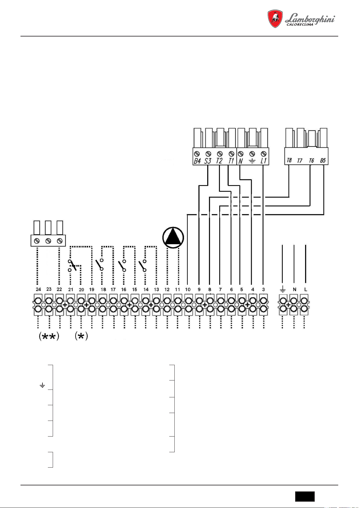
MEGAPREX N 720N ÷ 1060N
6.1.1 Фронтальныйвидпульта(рис.11)
Обозначения
1
Выключатель насоса
2
Выключатель горелки
3
Выключатель котла
4
Кнопка диагностики
5
Кнопка перезапуска предохранительного прессостата
6
Температура котловой воды
7
Индикатор работы котла
6.1.2 Схемаклеммнойколодкиэлектрическихподключений
8
Индикатор 1-й ступени горелки
9
Индикатор 2-й ступени горелки
10
Индикатор блокировки горелки
11
Индикатор срабатывания предохранительного прессостата
12
Регулировка термостата 2-й ступени TR1
13
Регулировка термостата 1-й ступени TR1
14
Место для установки терморегулятора
(*) Только пульты BT
(**) Только пульты BT 3 ступени
L
N 14
Питание панели управления
3
Питание горелки
4 17
5
Термостат 1-й ступени
6 19
7
Термостат 1-й ступени
8 21
9 Сигнал блокировки 22
10 Сигнал работы 2-й ступени 23
11
Питание насоса
12
cod. 3541O220 - Rev. 00 - 03/2018
13
Дистанционное включение котла
(если нет, соединить мостом)
15
Дистанционная защита котла
(если нет, соединить мостом)
16
Термостат температуры воздуха в помещении
18
20
Индикатор антиконденсатного насоса
Термостат 3-й ступени
IT
89

6.1.3 Электрическаясхемаподключениягорелкииоднофазногонасоса
Электрическаясхема
MEGAPREX N 720N ÷ 1060N
1 - (S1) Разрешение на дистанционное
2 - (TS1) Предохранительный термостат котла
3 - (S2) Внешняя противоаварийная защита
4 - (TR1) Термостат регулировки 1-го пламени
5 - (SA2) Выключатель горелки
6 - (N1) Цифровой термометр
7 - (B1) Термометр сопротивления воды
8 - (SB1) Кнопка диагностики термостата
9 - (TR2) Термостат регулировки 2-го пламени
10 - (TR2) Термостат регулировки 3-го пламени
11 - (XT1) Управление антиконденсатным насосом
12 - (S3) Термостат температуры воздуха в
13 - (TR3) Термостат
14 - (SA3) Выключатель циркуляционного насоса
15 - (P1) Циркуляционный насос
16 - (SA1) Выключатель котла
17 ПОДКЛЮЧЕНИЯ ГОРЕЛКИ
17 - (17/a) Блокировка горелки
17 - (17/b) Второе пламя
17 - (17/c) Авторизация для 1-го пламени
17 - (17/d) Авторизация для 2-го пламени
17 - (17/e) Питание горелки
17 - (17/f) Авторизация для 3-го пламени
включение
ТОЛЬКО ДЛЯ ПУЛЬТА 3-Й СТУПЕНИ
ТОЛЬКО ДЛЯ ПУЛЬТА
НИЗКОТЕМПЕРАТУРНОГО ТЕРМОСТАТА
помещении
90
IT
cod. 3541O220 - Rev. 00 - 03/2018
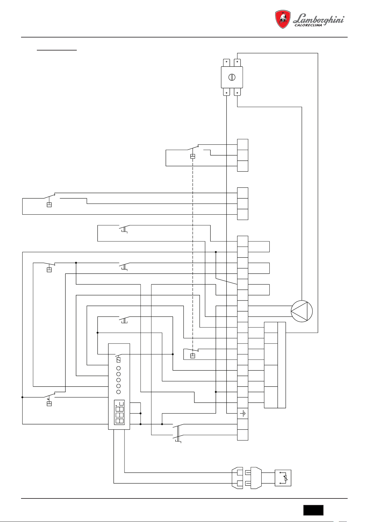
MEGAPREX N 720N ÷ 1060N
Схемаподключения
cod. 3541O220 - Rev. 00 - 03/2018
IT
91
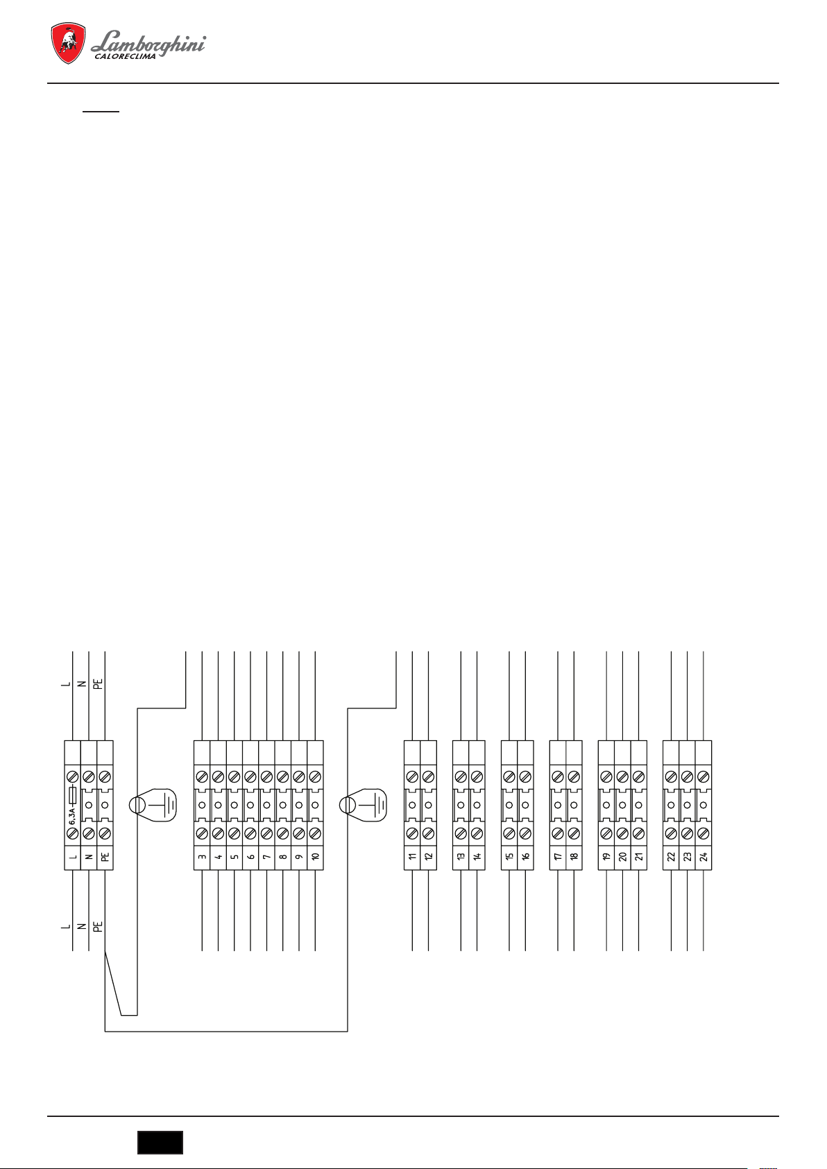
Колодки
Максимальный потребляемый
ток - 3 ампера
IIIIIIIIIII
MEGAPREX N 720N ÷ 1060N
Максимальный потребляемый
ток - 3 ампера
IIIII
Если отсутствует, установите мостовое соединение
I
III
Если отсутствует, установите мостовое соединение
III
Если отсутствует, установите мостовое соединение
III
ТОЛЬКО ДЛЯ ПУЛЬТА НИЗКОТЕМПЕРАТУРНОГО
IIIII
ТЕРМОСТАТА
IIIII
Источник питания 230 В пер. тока, 50–60 Гц, однофазный (фаза)
Источник питания 230 В пер. тока, 50–60 Гц, однофазный (нейтраль)
Источник питания 230 В пер. тока, 50–60 Гц, однофазный (заземлить)
Источник питания горелки 230 В пер. тока, 50–60 Гц, однофазный (заземление)
Источник питания 230 В пер. тока, 50–60 Гц, однофазный (фаза)
Источник питания 230 В пер. тока, 50–60 Гц, однофазный (нейтраль)
Сигнал работы горелки (1 пламя)
Сигнал работы горелки (1 пламя)
Сигнал работы горелки (2 пламя)
Сигнал работы горелки (2 пламя)
Сигнал блокировки горелки
Сигнал блокировки горелки
Источник питания насоса 230 В пер. тока, 50–60 Гц, однофазный (заземление)
Источник питания насоса 230 В пер. тока, 50–60 Гц, однофазный (фаза)
Источник питания насоса 230 В пер. тока, 50–60 Гц, однофазный (нейтраль)
Индикатор удаленного запуска котла
Индикатор удаленного запуска котла
Индикатор внешней противоаварийной защиты
Индикатор внешней противоаварийной защиты
Термостат температуры воздуха в помещении
Термостат температуры воздуха в помещении
Сигнал антиконденсатного насоса [общий контакт, COM]
Сигнал антиконденсатного насоса [нормально-разомкнутый контакт, NO]
Сигнал антиконденсатного насоса [нормально-замкнутый контакт, NC]
Термостат 2-го/3-го пламени горелки [общий контакт, COM]
Термостат 2-го/3-го пламени горелки [нормально-разомкнутый контакт, NO]
Термостат 2-го/3-го пламени горелки [нормально-замкнутый контакт, NC]
92
IT
cod. 3541O220 - Rev. 00 - 03/2018

MEGAPREX N 720N ÷ 1060N
IT
Temperatura mandata acqua caldaia
Interruttore bruciatore
IT
Interruttore bruciatore
IT
Temperatura mandata acqua caldaia
Strumento stato caldaia/Temperatura acqua
Interruttore bruciatore
Interruttore circolatore
IT
Interruttore bruciatore
IT
Temperatura mandata acqua caldaia
Strumento stato caldaia/Temperatura acqua
Circolatore acqua impianto
Interruttore bruciatore
Interruttore circolatore
Pulsante test
IT
Interruttore bruciatore
Interruttore circolatore
Pulsante test
IT
Temperatura mandata acqua caldaia
Strumento stato caldaia/Temperatura acqua
Circolatore acqua impianto
Consenso accensione remoto
Interruttore bruciatore
Interruttore circolatore
Pulsante test
Termostato 1° stadio bruciatore
IT
Interruttore bruciatore
Interruttore circolatore
Pulsante test
Termostato 1° stadio bruciatore
IT
Temperatura mandata acqua caldaia
Strumento stato caldaia/Temperatura acqua
Circolatore acqua impianto
Consenso accensione remoto
Interruttore bruciatore
Interruttore circolatore
Pulsante test
Termostato 1° stadio bruciatore
IT
Interruttore bruciatore
Interruttore circolatore
Pulsante test
Termostato 1° stadio bruciatore
Termostato 2° stadio bruciatore
Termostato di sicurezza caldaia
IT
Temperatura mandata acqua caldaia
Strumento stato caldaia/Temperatura acqua
Circolatore acqua impianto
Consenso accensione remoto
Consenso di sicurezza esterno
Termostato ambiente
Interruttore accensione caldaia
Interruttore bruciatore
Interruttore circolatore
Pulsante test
Termostato 1° stadio bruciatore
Termostato 2° stadio bruciatore
Termostato di sicurezza caldaia
Обозначенияустройствисимволынаэлектрическойсхеме
B1
QG2Температура воды на выпуске
N1
QG2Состояние котла / температура воды
P1
QG2Циркуляционный насос
S1
QG2Разрешение на дистанционное включение
S2
QG2Внешняя противоаварийная защита
S3
QG2Термостат температуры воздуха в помещении
SA1
QG2Выключатель котла
SA2
QG2Выключатель горелки
SA3
QG2Выключатель циркуляционного насоса
SB1
QG2Кнопка диагностики
TR1
QG2Термостат 1-й ступени горелки
TR2
QG2Термостат 2-й/3-й ступени горелки
TS1
QG2Предохранительный термостат котла
6.2 ПультуправленияEBM(EfcientBoilerManagement)(рис.12)
C16015150 — пульт управления EBM (Efficient Boiler Management)
6.2.1 Пульт(рис.12)
Панель управления EBM, не поставляемая в стандартной комплектации с котлом, позволяет, в частности, выполнять следующие функции:
- выбор языка;
- выбор режима работы: отопление, экономичная работа и программирование времени, а также «отпуск»;
- управление насосом котла;
- управление антиконденсатным насосом;
- управление одноступенчатой горелкой;
- управление двухступенчатой горелкой;
- управление модулирующей горелкой;
- Учет часов работы ступеней горелки;
- просмотр параметров котла;
- просмотр аварийных сообщений;
- функция погодозависимости (при наличии датчика наружной температуры).
Панель может управлять установкой следующей максимальной конфигурации:
- одна высокотемпературная зона, управление насосом;
- одна или две низкотемпературных зоны со смесительным клапаном и насосом;
- бойлер ACS, работа насоса регулируется в зависимости от температуры в бойлере.
Другие применения.
Может использоваться в каскадах из не более 16 котлов, организованных по системе с конфигурацией «главный — подчиненный». Возможна
интеграция с солнечной установкой.
cod. 3541O220 - Rev. 00 - 03/2018
IT
93

6.2.2 Электрическиесхемы
Электрическаясхема
MEGAPREX N 720N ÷ 1060N
1 - (2TS1) Предохранительный термостат
2 - (2XT1)
3 - (2BU1) ПОДКЛЮЧЕНИЯ ГОРЕЛКИ
3 - (2BU1) - A Блокировка горелки
3 - (2BU1) - B Авторизация для 1-го пламени
3 - (2BU1) - C Питание горелки МАКС. 3 A
котла
Внешняя противоаварийная защита
Сигнал срабатывания
предохранительного термостата
(230 В пер. тока)
94
IT
cod. 3541O220 - Rev. 00 - 03/2018

MEGAPREX N 720N ÷ 1060N
Схемаподключенийцентральногоблокауправления(часть1)
1 - (3P2) Антиконденсатный насос
2 - (3P1) Циркуляционный насос
3 - (3B1) Датчик температуры в возвратном
4 - (3B1) Датчик наружной температуры
Макс. 2 A
Возможно использование для
авторизации.
Макс. 2 A
Возможно использование для
авторизации.
трубопроводе
ОПЦИОНАЛЬНО
Используйте датчик NTC 10K.
ОПЦИОНАЛЬНО
Используйте датчик NTC 10K.
cod. 3541O220 - Rev. 00 - 03/2018
IT
95

Схемаподключенийцентральногоблокауправления(часть2)
MEGAPREX N 720N ÷ 1060N
1 SAFETY-LOOP
2 - (4B1) Датчик температуры котловой воды
3 - (4N1) Пульт управления
Установите мостовое соединение,
если нет другого разрешения от
системы безопасности установки
Используйте датчик NTC 10K.
AVS 37.294
96
IT
cod. 3541O220 - Rev. 00 - 03/2018

MEGAPREX N 720N ÷ 1060N
Схемаклеммпульта
QG - M
Главная колодка
Источник питания 230 В пер. тока, 50–60 Гц, однофазный (фаза)
Источник питания 230 В пер. тока, 50–60 Гц, однофазный (нейтраль)
Источник питания 230 В пер. тока, 50–60 Гц, однофазный (заземлить)
Схемаклеммцентральногоблокауправления
QG
Клемма RVS63.283
BM - 2BU1 - Источник питания горелки 230 В пер. тока, 50–60 Гц, однофазный (заземление)
BM - 2BU1 - Источник питания горелки 230 В пер. тока, 50–60 Гц, однофазный (фаза)
BM - 2BU1 - Источник питания горелки 230 В пер. тока, 50–60 Гц, однофазный (нейтраль)
BM - 2BU1 - Сигнал 1-го пламени горелки
BM - 2BU1 - Сигнал 1-го пламени горелки
BM - 2BU1 - Сигнал блокировки горелки
BM - 2XT1 - Сигнал
BM - 2XT1 - Сигнал
предохранительного термостата (230 В пер. тока)
предохранительного термостата (230 В пер. тока)
BM - Сигнал безопасности системы
BM - Сигнал безопасности системы
BM - 3P1 - Водяной насос котла (230 В пер. тока - фаза)
BM - 3P1 - Водяной насос котла (230 В пер. тока - заземление)
BM - 3P1 - Водяной насос котла (230 В пер. тока - нейтраль)
BM - 3P2 - Антиконденсатный насос (230 В пер. тока - фаза)
BM - 3P2 - Антиконденсатный насос (230 В пер. тока - заземление)
BM - 3P2 - Антиконденсатный насос (230 В пер. тока - нейтраль)
I
I
Максимальный
I
I
потребляемый
I
I
ток - 3 ампера
I
I
I
I
Если не нужно, установите
I
I
мостовое соединение
I
I
МАКС. 2 A
I
I
I
I
I
I
I
МАКС. 2 A
I
I
I
BM - 4B1 - Датчик температуры котла
BM - 4B1 - Датчик температуры котла
BM - 3B3 - Датчик наружной температуры
BM - 3B3 - Датчик наружной температуры
BM - 3B1 - Датчик температуры в обратном трубопроводе
BM - 3B1 - Датчик температуры в обратном трубопроводе
cod. 3541O220 - Rev. 00 - 03/2018
I
I
ОПЦИОНАЛЬНО
I
IT
97

Обозначенияустройствисимволынаэлектрическойсхеме
MEGAPREX N 720N ÷ 1060N
2BU1
BM2Горелка котла
2HL1
QG2Индикатор питания панели (230 В пер. тока)
2HL2
Аварийный индикатор срабатывания
QG
предохранительного термостата
2
2SB1
QG2Главный выключатель котла
2SB2
QG2Выключатель горелки
2TS1
QG2Предохранительный термостат котла
2XT1
Сигнал срабатывания предохранительного
BM
термостата (230 В пер. тока)
2
3B1
BM3Датчик температуры в обратном трубопроводе
3B3
BM3Датчик наружной температуры
3N1
QG3ГЛАВНЫЙ блок управления (RSV 63 283/109)
3P1
BM3Насос
3P2
BM3Антиконденсатный насос
4B1
BM4Датчик температуры котловой воды
4N1
Пользовательский интерфейс Siemens
QG
AVS37.294
4
6.3 Примечанияпоподключениям
Кабель питания пульта типа FG7 RN–F 3G1,5 уже подключен к клеммной колодке. В случае замены убедитесь в том, что выбран подходящий кабель,
соответствующий действующим нормам. Подача напряжения на горелку осуществляется непосредственно с соединительной коробки, если сеть
является однофазной и с максимальным током 3 А. Подача напряжения на насос осуществляется непосредственно с соединительной коробки, если
сеть является однофазной и с максимальным током 3 А. Если потребляемый ток горелки или насоса выше предусмотренного или сеть является
трехфазной, к выходам соединительной коробки должны подключаться силовые реле.
Дистанционный запуск позволяет управлять котлом с удаленного диспетчерского пульта. Если он не используется, то необходимо установить мостовое
соединение. Внешняя противоаварийная защита котла представляет собой дополнительный способ остановки котла. Если она не используется, то
необходимо установить мостовое соединение. Контакт комнатного термостата управляет только циркуляционным насосом. Если он не используется,
то необходимо установить мостовое соединение.
7. ВВОДВЭКСПЛУАТАЦИЮ
7.1 Предварительныепроверки
После выполнения гидравлических, электрических и топливных подключений к установке перед первым запуском проверьте, что:
- расширительный бак и предохранительный клапан правильно подключены и не могут быть перекрыты;
- датчики регулировочных и предохранительных термостатов и термометра надежно зафиксированы внутри соответствующих гильз;
- во всех дымогарных трубах установлены турбулизаторы;
- система заполнена водой и воздух полностью стравлен;
- насос или насосы работают правильно;
- гидравлические и электрические соединения, устройства безопасности и дымоходы подключены в соответствии с действующими национальными
и местными нормами;
- горелка установлена в соответствии с инструкциями, изложенными в техническом руководстве изготовителя;
- напряжение и частота электрической сети находятся в соответствии с техническими характеристиками горелки и электрооборудования котла;
- система в состоянии принять тепло, которое будет произведено теплогенератором;
- рециркуляционный насос установлен так, как описано в разд. 5.5.5.
98
IT
cod. 3541O220 - Rev. 00 - 03/2018

MEGAPREX N 720N ÷ 1060N
7.2 Первыйзапуск
После успешного выполнения всех проверок, описанных в предыдущем разделе, можно выполнить первый запуск горелки. Эта процедура должна
выполняться специалистом, аккредитованным изготовителем горелки. Этот специалист несет личную ответственность за калибровку и наладку
горелки в пределах заявленного и утвержденного диапазона мощности. После открытия запирающих топливных задвижек и проверки отсутствия
утечек в линии подачи топлива, переведите все выключатели в положение ВКЛ. Теперь горелка готова к первому запуску и настройке, которые
должны производиться уполномоченным специалистом.
При первом запуске убедитесь, что передняя дверца, фланец горелки и подключения к дымовой трубе являются газоплотными, а на входе в дымоход
присутствует небольшое отрицательное давление (тяга). Производительность топливоподачи должна соответствовать техническим характеристикам
котла и ни в коем случае не должна превышать максимального значения заявленной расчетной мощности. Температура уходящих газов никогда не
должна быть ниже 160 °С.
7.3 Остановкакотла
- Установите минимальное значение рабочей температуры.
- Обесточьте горелку и перекройте подачу топлива.
- Оставьте насосы в работе до тех пор, пока их не отключит термостат.
- Обесточьте электрощит.
8. OБCЛУЖИBAHИE
8.1 Общиеуказания
Периодическое обслуживание необходимо для обеспечения безопасности, эффективности и длительного срока эксплуатации оборудования.
Все операции должны выполняться квалифицированным персоналом. Все операции по чистке и обслуживанию котла должны производиться при
закрытой подаче топлива и отключенном электроснабжении.
Для правильной работы и максимальной эффективности котла камеру сгорания, дымогарные трубы и дымовой коллектор необходимо регулярно
чистить.
8.2 Текущееобслуживание
Периодичность чистки не может быть определена заранее, так как она зависит от типа используемого топлива, интенсивности использования,
характеристик системы и т. д.
В любом случае минимальная периодичность для разных типов топлива составляет:
- газ: один раз в год;
- дизельное топливо: два раза в год.
В любом случае следует в первую очередь придерживаться действующих местных норм и стандартов.
Во время текущего обслуживания, после удаления турбулизаторов, прочистите щетками трубный пучок и топку. Откройте инспекционные лючки и
удалите нагар и отложения, скопившиеся в дымовом коллекторе. Для более интенсивной очистки удалите задний дымовой коллектор и, при наличии
повреждений, замените уплотняющую манжету. Убедитесь, что система отвода конденсата не заблокирована. Убедитесь в том, что устройства
измерения и управления работает правильно.
Замерьте расход подпиточной воды, и, после проведения анализа воды, проведите профилактическую очистку от накипи.
При повторяющихся подпитках растворенные в воде соли кальция и магния вызывают отложения накипи в котле и перегрев металлических
поверхностей, что может привести к повреждениям, которые нельзя отнести ни к недостаткам использованных при изготовлении агрегата материалов,
ни к производственному браку. Соответственно, такие случаи не будут являться гарантийными. После окончания работ по чистке и обслуживанию
и повторного запуска котла проверьте газоплотность дверцы и дымового коллектора, и, в случае обнаружения утечки продуктов сгорания, замените
соответствующие прокладки.
Выполненные операции должны быть занесены в журнал эксплуатации установки.
8.3 Специальноеобслуживание
Специальное обслуживание производится в конце отопительного сезона или перед продолжительной остановкой котла.
Осуществите все операции, описанные в предыдущем разделе, а также:
- проверьте турбулизаторы на предмет износа;
- прочистите газоходы и обработайте их раствором каустической соды; после высыхания протрите все поверхности масляной тряпкой;
- гигроскопические вещества (негашеная известь, силикагель в небольших емкостях) следует поместить внутрь топки, которая затем должна быть
герметично закрыта, так чтобы предотвратить свободный доступ воздуха;
- не сливайте систему и котел;
- обработайте винты, гайки, штифты дверцы графитовой смазкой;
Выполненные операции должны быть занесены в журнал эксплуатации установки.
8.4 Чисткакотла(рис.13)
Чистка котла производится следующим образом:
- вместе к котлом поставляется специальная щетка для чистки дымовых труб;
- откройте переднюю дверцу (1) и удалите турбулизаторы (2);
- прочистите внутренние поверхности камеры сгорания и газоходы, используя щетку (3) или другое подходящее для этой цели приспособление;
- через открытый лючок обслуживания (4) удалите отложения, накопившиеся в дымовом коллекторе; для лучшей очистки удалите крышку дымового
коллектора (5) и замените уплотняющую прокладку перед повторной сборкой;
- периодически проверяйте, что система слива конденсата (6) не закупорена.
cod. 3541O220 - Rev. 00 - 03/2018
IT
99

MEGAPREX N 720N ÷ 1060N
8.5 Проверкаработоспособностикотла
Перед запуском и проверкой работоспособности котла убедитесь, что:
- турбулизаторы располагаются внутри теплообменных труб;
- вентили гидравлического контура и системы подачи топлива открыты;
- топливо имеется в наличии;
- расширительный бак достаточно наполнен;
- холодное давление в гидравлической системе превышает 1 бар и не достигает максимального разрешенного давления котла;
- воздух стравлен из гидравлической системы;
- электрические подключения к сети питания и устройствам котла (горелке, насосу, панели управления, термостату и т. д.) полностью закончены;
- соединение между фазой и нейтралью проверено, а установка заземлена.
После окончания описанных операций для запуска котла необходимо выполнить следующие действия:
- если система оборудована терморегулятором или хронотермостатом, убедитесь, что он находится в положении «включено»;
- установите комнатный хронотермостат или терморегулятор на желаемое значение температуры;
- переведите главный выключатель системы в положение «включено»;
- отрегулируйте термостат котла, расположенный на панели управления;
- переведите выключатель котла на панели управления в положение «включено» и убедитесь, что зажегся зеленый индикатор.
Котел перейдет в режим запуска и будет оставаться в нем до достижения установленной температуры. Если во время запуска или работы котла
возникнут какие-либо неисправности, агрегат будет «ОСТАНОВЛЕН», а на горелке и панели управления зажгутся красные индикаторы. В случае
блокировки котла следует выждать не менее 30 секунд перед повторным запуском. Для того чтобы восстановить условия запуска, нажмите кнопку
«выключатель/пилот» на горелке и дождитесь появления пламени. Если горелка не зажглась, операция может быть повторена максимум 2–3 раза,
после чего следует обратиться:
- к информации, поставляемой в инструкции изготовителем горелки;
- к разделу «ДИАГНОСТИКА РАБОТЫ КОТЛА»;
- к схеме электрических подключений, поставляемой с пультом управления. После запуска котла, убедитесь, что он останавливается, запустите его
снова следующим образом:
- отрегулируйте настройку термостата котла;
- переключите выключатель котла на панели управления;
- настройте термостат температуры воздуха в помещении, таймер или терморегулятор;
- проверьте, что роторы насосов свободно вращаются в правильном направлении;
- проверьте срабатывание полной остановки котла, используя главный выключатель.
Если все устройства сработали правильно, перезапустите установку, проверьте качество сгорания (по анализу уходящих газов), расход топлива и
газоплотность дверцы и дымового коллектора.
8.6 Диагностикаработыгорелки
- Обратитесь к руководству по эксплуатации горелки;
- при обслуживании горелки выполняйте операции согласно действующим нормам.
100
IT
cod. 3541O220 - Rev. 00 - 03/2018
 Loading...