

LAMBORGHINI Vela XN 24 MB/IT Installation And Maintenance Manual
CALDAIA MURALE A GAS CON BOLLITORE AD ACCUMULO - ALTO RENDIMENTO - MODULANT
EWALL-HUNG GAS BOILER WITH HOT WATER STORAGE TANK - HIGH EFFICIENCY - MODULATING UNIT
CALDERA MURAL A GAS CON ACUMULADOR - ALTO RENDIMIENTO - MODULANTE
CALDEIRA DE PAREDE A GÁS COM TERMOACUMULADOR - ALTO RENDIMENTO - MODULANTE
MANUALE DI
INSTALLAZIONE E
MANUTENZIONE
PREGASI CONSEGNARE
L'INSERTO "MANUALE D'USO"
AL SIG. UTENTE
TENGAN LA AMABILIDAD
DE ENTREGARLE AL USUARIO
EL FOLLETO “MANUAL DE USO”
PLEASE MAKE SURE THAT
THE “USE MANUAL” IS
HANDED OVER TO THE USER
FAVOR ENTREGAR O
“MANUAL DE USO”
AO SR. UTENTE
INSTALLATION
AND MAINTENANCE
MANUAL
MANUAL PARA
LA INSTALACIÓN Y EL
MANTENIMIENTO
MANUAL DE
INSTALAÇÃO E
MANUTENÇÃO
N
24 MB/IT

Read carefully all warnings and instructions contained in this manual as they give
important instructions regarding safety, installation and maintenance. Keep this manual
for future reference. Installation must be carried out by qualified personnel who will
be responsible for respecting existing safety regulations.
GB
ENGLISH

24
Congratulations....
......on an excellent choice. We thank you for the preference accorded to our products.
LAMBORGHINI CALORECLIMA has been actively present in Italy and throughout the world
since 1959 with a widespread network of agents and concessionary agents to constantly
guarantee the presence of our product on the market.
Alongside this is the support of a technical service, “LAMBORGHINI SERVICE”, which is
entrusted with the qualified servicing of the product.
For the installation and positioning of the boiler:
CAREFULLY OBSERVE THE LOCAL REGULATIONS IN FORCE
INDEX PAGE
GENERAL INSTRUCTIONS _____________________________________________ 25
DESCRIPTION _______________________________________________________ 26
MAIN COMPONENTS ________________________________________________ 27
DIMENSIONS _______________________________________________________ 28
TECHNICAL FEATURES ________________________________________________ 28
GAS - NOZZLE CALIBRATION __________________________________________ 29
ELECTRICAL CONNECTIONS - WIRING DIAGRAMS _______________________ 30
MALFUNCTIONS AND ADJUSTMENTS __________________________________ 32
WATER CONNECTION _______________________________________________ 33
WATER CIRCUIT ______________________________________________________ 34
INSTALLATION_______________________________________________________ 35
START-UP ___________________________________________________________ 35
FLUE EXHAUST CONNECTION _________________________________________ 36
ADJUSTMENTS ______________________________________________________ 37
SWITCHING OFF ____________________________________________________ 38
MAINTENANCE _____________________________________________________ 38
KNOB ASSEMBLY INSTRUCTIONS ______________________________________ 39
OPERATION WITH DIFFERENT TYPES OF GAS ____________________________ 41
FAULT-FINDING CHART _______________________________________________ 42

25
GENERAL INSTRUCTIONS
● This booklet constitutes an integral and essential part of the product.
Read carefully the instructions contained in this booklet as they provide important directions
regarding the safety of installation, use and maintenance. Preserve this booklet with care for any
further consultation. The installation of the boiler must be carried out in compliance with current
regulations, according to the instructions of the manufacturer and by qualified personnel. An
incorrect installation can cause injury or damage to persons, animals and objects, for which the
manufacturer cannot be held responsible.
● After removing the packaging materials, check the content integrity. In case of doubt, do not use
the unit and contact the supplier. The packaging material (wooden crates, nails, clips, plastic
bags, foam, etc.) must not be left within reach of children as they are potential sources of danger.
● This boiler is designed to heat water to a temperature below boiling (atmospheric pressure). It
must be connected to a heating system compatible with its performances and output.
● This appliance should be destined only for the use for which it has been expressly envisaged. Any
other use is to be considered improper and therefore dangerous. The manufacturer cannot be
considered responsible for any damages caused from improper, erroneous or unreasonable use.
ALL INSTALLATION, MAINTENANCE AND GAS CONVERSION OPERATIONS MUST BE CARRIED OUT
BY AUTHORISED SKILLED TECHNICIANS.
TO ENSURE THAT BOILER IS INSTALLED CORRECTLY AND THAT IT FUNCTIONS PROPERLY, WE
RECOMMEND THAT ONLY LAMBORGHINI ACCESSORIES AND SPARE PARTS BE USED.
ON NOTICING THE SMELL OF GAS DO NOT TOUCH ANY ELECTRIC SWITCH. OPEN DOORS AND
WINDOWS. SHUT OFF THE GAS TAPS.
INSTALL THE BOILER ON WALLS WHICH ARE AS WIDE AS OR WIDER THAN THE BOILER ITSELF.

26
DESCRIPTION
These boilers are fully automatic and gas control is effected by an electronic control unit having the
following characteristics:
- continuous modulation mode on both circuits;
- possibility to adjust the heating output;
- possibility to adjust the slow ignition;
- “anti-Legionnaire’s” function
They are equipped with:
- Safety flow-switch;
-Total safety thermostat;
- High efficiency flue gas exchanger;
- 60-liter tank in stainless steel for plenty of hot water
- Electric 3-way valve
VELA X N 24 MB W TOP
Electronic ignition with ionisation flame control.
Combustion and fume discharge are of the atmospheric type. Fitted with FLUE CONTROL fume evacuation device.
FLUE CONTROL THERMOSTAT
VELA X N MB boilers are fitted with the FLUE CONTROL device to control evacuation of fumes. An
increase in fume temperature in the down-draught diverter indicates an anomaly in fume evacuation.
The FLUE CONTROL probe in the down-draught diverter detects variations in temperature and shuts
down the boiler. Efficient operation of this safety system depends on observance of the following:
- Do not deactivate the FLUE CONTROL thermostat.
- Inspect the boiler and the flue immediately if the FLUE CONTROL device trips frequently.
- If the FLUE CONTROL device is changed make sure you observe assembly and probe positioning
instructions carefully and use only original LAMBORGHINI spare parts.
If there is a fume evacuation anomaly act quickly to prevent the formation of Carbon Monoxide, a
poisonous gas that causes intoxication and potentially fatal harm to both humans and animals.
27
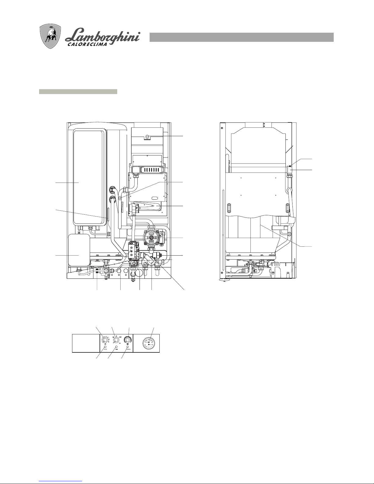
MAIN COMPONENTS
LEGEND
1 Hot water expansion tank
2 Water-heater sensor
3 Heating expansion tank
4 Flue control
5 Delivery sensor
6 Burner
7 Circulator
8 Electric 3-way valve
9 Automatic by-pass
10 Safety flow-switch
11 Modulating coil
12 Gas valve
13 Hot water circuit:
- 8-bar safety valve
- Non-return valve
- Inspection filter
14 Total safety thermostat
15 Fume exchanger
16 Stainless steel water-heater
17 Thermohydrometer
18 Malfunction warning light
19 ON/OFF warning light
20 Lock-out warning light
21 Hot water adjustment potentiometer
22 Function selector
23 Heating adjustment potentiometer
1
2
3
5
P
E
T
S
1
P
E
T
S
1
10 9111213
7
8
4
6
14
15
16
17232221
181920
28
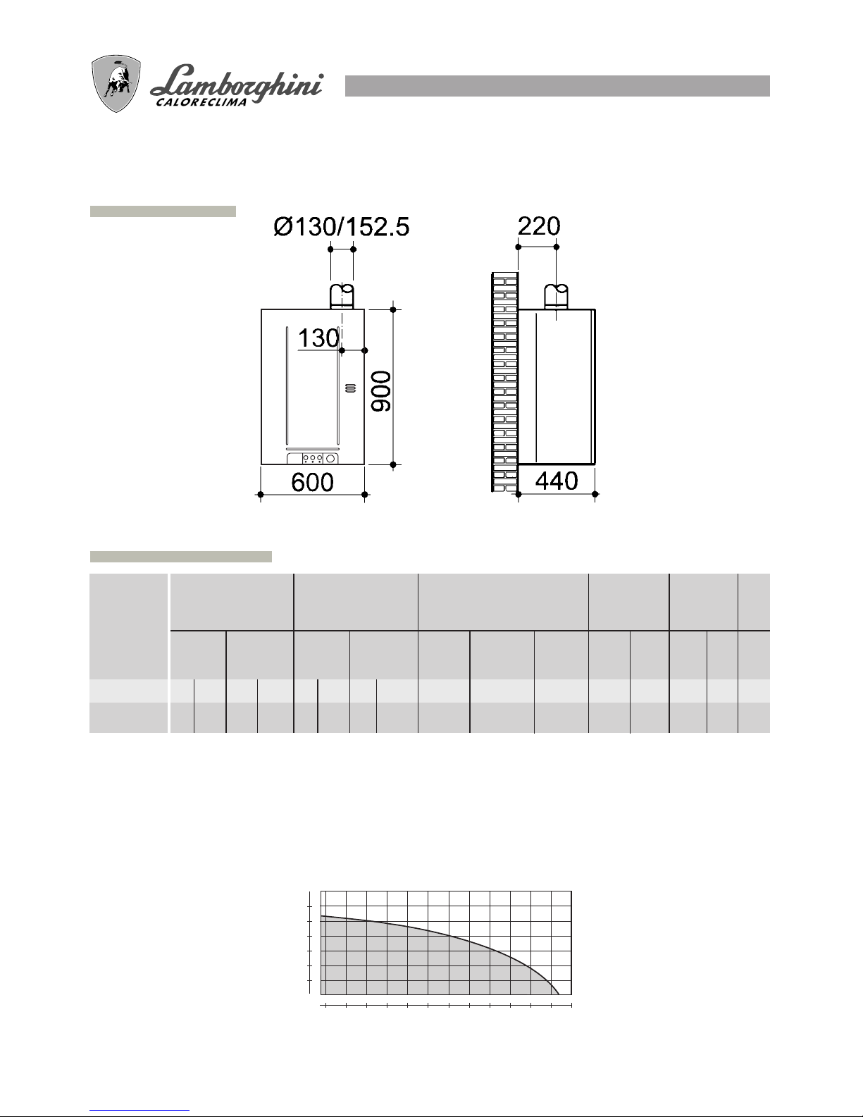
DIMENSIONS mm
CIRCULATING PUMP FEATURES
System delivery/pressure
300 400
500 600 700
800
900 1000 1100 1200
1300 1400 1500
600
500
400
300
200
100
Residual pressure mbarr
Delivery (l/h)
Boiler version: mod. MB type B11 BS Max. water temperature 90°C
Rated gas pressure: Natural gas 20 mbar
Category: II 2H3+ B 28/30 mbar - P 37 mbar
TECHNICAL FEATURES
MODELL
Input Output
kW kcal/h kW kcal/h
l
kg
Hot
water
l
kW
kW
kcal/h
Operating
pressure
Heating
circuit
max.
Hot
water
circuit
bar
bar
Thermal capacity Min. thermal
capacity
Hot water supply
Expansion
tank
Weight
Input
Output
kcal/h
VELA X N 24
26
22360
23,4 20124
12,1
10406
10,43
8970
3
8
8263
Peak output
in first 10
minutes
Supply
∆
30 °C
Water
heater
capacity
ll
l/min
Heating
60
10 150
VELA X N 24 MB W TOP/IT
Operation of safety flow switch: minimum ∆P 1,2 mt.
29
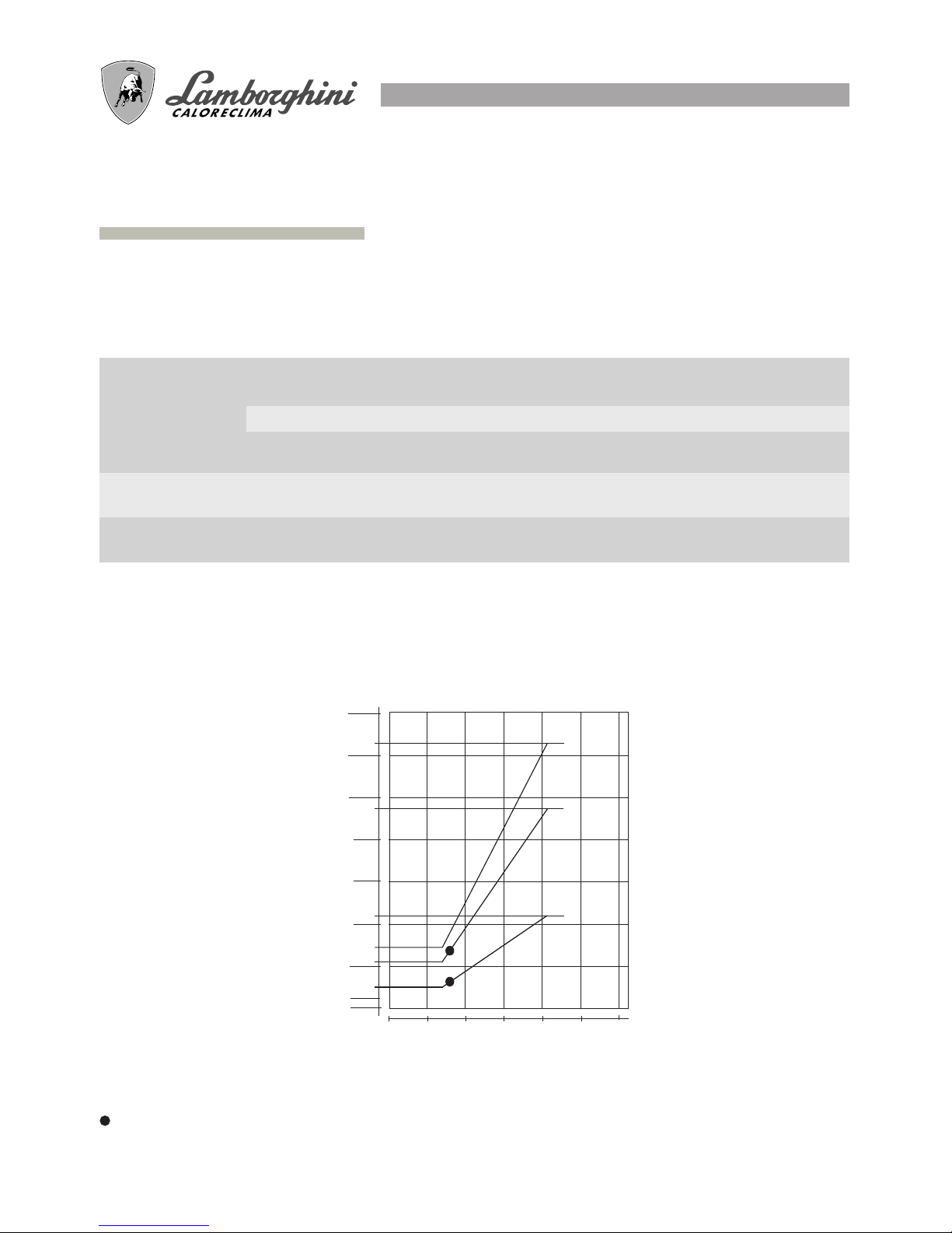
The boilers leave the factory calibrated and ready to operate with NATURAL GAS and LIQUID GAS.
For proper calibration, see the table below:
BURNER PRESSURE CURVES - OUTPUT
GAS - NOZZLE CALIBRATION
Slow ignition adjustment
3 mbars NATURAL GAS
7 mbars LIQUID GAS
VELA X N 24 MB
10
kW
mbar
2,5
11
5,5
23,7
2515 20
10
5
GN 11
0
15
20
25
B 23,7
kPa
30 35
0
30
35
1
0,5
0
1,5
2
2,5
3
3,5
1
31,4
P 31,4
0,1
1009DIS1385
7,2
Jets pressure mbar
Gas type
NATURAL GAS
(G20-20mbar)
LIQUID GAS B
(G30-28/30mbar)
LIQUID GAS P
(G31-37mbar)
Burner jets
L.C.V.
kcal/m
3
8.550
29.330
22.360
Delivery
VELA X N 24
max.
11
23,7
31,4
2,5
5,5
7,2
min. m3/h
2,6
0,76
1
VELA X N 24
Ø mm.
1,25
0,77
0,77
VELA X N 24
30
ELECTRICAL CONNECTIONS - WIRING DIAGRAMS
The boiler must be connected to an earthed, single-phase 230V - 50 Hz mains supply by means of a
three-wire cable, ensuring that connections to the LINE and NEUTRAL terminals are made correctly.
A bipolar switch must be used with contacts opening to at least 3 mm.
The power lead must only be replaced by another with the following characteristics: “HAR H05 vv-F” 3
x 1.00 mm2. (You are strongly advised to use original LAMBORGHINI accessories and spare parts
only).
Installation must be made in compliance with safety REGULATIONS IN FORCE.
Make a good earth connection.
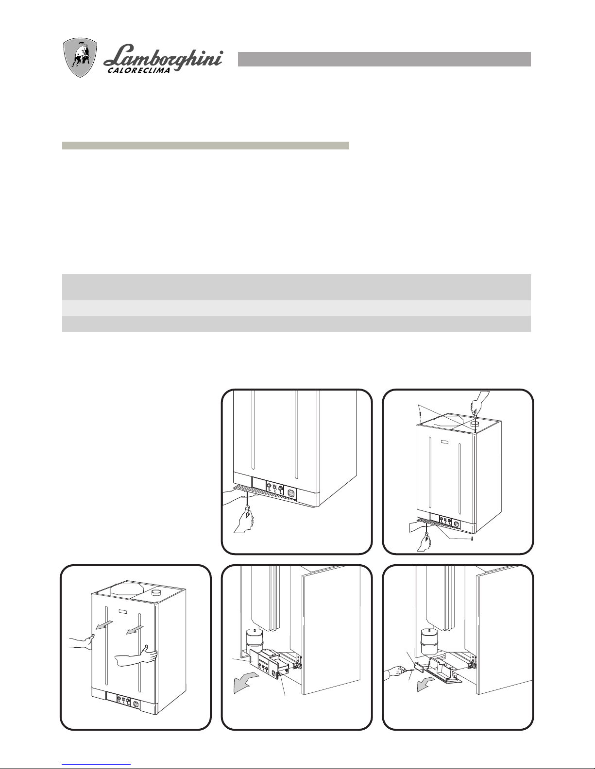
To gain access to the electrical panel which houses the power supply terminal block and any connection to a
room thermostat, proceed as follows:
Voltage
V
230
Frequency
Absorbed power
kW
Hz
Noise level
dB (A)
● Disconnect the boiler power
supply
● Undo the two grating screws
(fig.1)
● Undo the four shell attachment
screws A (fig.2)
● Remove the shell (fig.3)
● To gain access to the electrical
and electronic components
loosen screws B and pull the
entire panel outwards (fig.4).
Tilt it downwards and undo the
screws C on the cover D
fig.3
fig.4
50
fig.1 fig.2
fig.5
VELA X N 24
51
Protection
index
IP
44
VELA X N 24
0,120
D
C
B
B
A
A
 Loading...