

LAMBORGHINI ECO P N Series, ECO 3, 4 P N, ECO 5, 5 P N Instructions For Use, Installation And Maintenance
ECO P N
6
cod. 3541S060 - Rev. 00 - 05/2019
IT -
ISTRUZIONE PER L’USO L'INSTALLAZIONE E LA MANUTENZIONE
EN -
INSTRUCTIONS FOR USE, INSTALLATION AND MAINTENANCE
ES -
INSTRUCCIONES DE USO, INSTALACIÓN Y MANTENIMIENTO
RO
-
INSTRUCğIUNI DE UTILIZARE, INSTALARE ùI ÎNTRETINERE
BG HR - UPUTE ZA UPORABU, POSTAVLJANJE I ODRŽAVANJE
EL HU - HASZNÁLATI, BESZERELÉSI ÉS KARBANTARTÁSI UTASÍTÁS
SR
ɂɇɋɌɊɍɄɐɂɂ ɁȺ ɍɉɈɌɊȿȻȺ, ɂɇɋɌȺɅɂɊȺɇȿ ɂ ɌȿɏɇɂɑȿɋɄɈ ɈȻɋɅɍɀȼȺɇȿ
ȅǻǾīǴǼȈ ȋȇdzȈǾȈ, ǼīȀǹȉDZȈȉǹȈǾȈ Ȁǹǿ ȈȊȃȉdzȇǾȈǾȈ
- ɍɉɍɌɋɌȼɈ ɁȺ ɍɉɈɌɊȿȻɍ, ɆɈɇɌȺɀɍ ɂ ɈȾɊɀȺȼȺȵȿ
This symbol indicates “CAUTION” and is placed next to all safety warnings. Strictly follow these instructions in order to avoid
danger and damage to persons, animals and things
This symbols calls attention to a note or important notice.
This symbol, which is used on the product, packaging or documents, means that at the end of its useful life, this product must
not be collected, recycled or disposed of together with domestic waste.
Improper management of electric or electronic waste can lead to the leakage of hazardous substances contained in the product. For the purpose of preventing damage to health or the environment, users are kindly asked to separate this equipment
from other types of waste and to ask for it to be dealt with by the municipal waste service or dealer under the conditions and
according to the methods set down in national and international laws transposing the Directive 2012/19/EU.
Separate waste collection and recycling of unused equipment helps to save natural resources and to guarantee that this waste
is processed in a manner that is safe for health and the environment.
For more information about how to collect electric and electronic equipment and appliances, please contact your local Council
or Public Authority competent to issue the relevant permits.
E
ECO P N
B
• Read the warnings in this instruction booklet carefully since they provide important information on safe installation, use and
maintenance.
• This instruction booklet is an integral part of
the product and must be kept with care by
the user for future reference.
• If the unit is sold or transferred to another
owner or if it is to be moved, always make
sure the booklet accompanies the boiler so
that it can be consulted by the new owner
and/or installer.
• Installation and maintenance must be carried out by professionally qualified personnel, according to the current regulations
and the manufacturer's instructions.
• Incorrect installation or inadequate maintenance can result in damage or injury. The
manufacturer declines any responsibility
for damage caused by errors in installation
and use or by failure to follow the manufacturer's instructions.
• Before carrying out any cleaning or maintenance operation, disconnect the unit from
the electrical power supply using the switch
and/or the special cut-off devices.
• In case of a fault and/or poor operation, deactivate the unit and do not try to repair it or
directly intervene. Contact professionally
qualified personnel. Any repair/replacement of products must only be carried out
by qualified personnel using original re-
placement parts. Failure to comply with the
above could affect the safety of the unit.
• Periodical maintenance carried out by
qualified personnel is essential to ensure
proper operation of the unit.
• This unit must only be used for the purpose
for which it was designed. Any other use is
considered improper and therefore hazardous.
• After removing the packing, check the integrity of the contents. The packing materials are potentially hazardous and must not
be left within the reach of children.
• The unit must not be used by people (including children) with limited physical, sensory or mental abilities or without
experience and knowledge of it, unless instructed or supervised in its use by someone responsible for their safety.
• In case of doubt do not use the unit. Contact the supplier.
• The unit and its accessories must be disposed of appropriately, in conformity with
the current regulations.
• The images given in this manual are a simplified representation of the product. In this
representation there may be slight and insignificant differences with respect to the
product supplied.
The CE marking certifies that the products meet the essential requirements of the relevant directives in force.
The declaration of conformity may be requested from the manufacturer.
COUNTRIES OF DESTINATION: IT - ES - RO - BG - HR - GR - HU - RS
cod. 3541S060 - Rev. 00 - 05/2019
27EN
ECO P N
1 Operating instructions .......................................................................................................... 29
1.1 Introduction...........................................................................................................................................29
1.2 Control panel ........................................................................................................................................ 29
1.3 Lighting and shutdown .........................................................................................................................30
1.4 Adjustments..........................................................................................................................................31
1.5 Operating instructions .......................................................................................................................... 37
1.6 Cleaning the burner grille .....................................................................................................................37
2 Installation.............................................................................................................................. 38
2.1 General Instructions ............................................................................................................................. 38
2.2 Installation in boiler...............................................................................................................................38
2.3 Electrical connections...........................................................................................................................41
2.4 Fuel supply ...........................................................................................................................................41
2.5 Connection to an external tank for domestic hot water production ...................................................... 42
3 Service and maintenance......................................................................................................44
3.1 Commissioning..................................................................................................................................... 44
3.2 Maintenance......................................................................................................................................... 45
3.3 Troubleshooting....................................................................................................................................47
4 TECHNICAL DATA AND CHARACTERISTICS ..................................................................... 48
4.1 Dimensions...........................................................................................................................................48
4.2 General view and main components ....................................................................................................49
4.3 Technical data table ............................................................................................................................. 49
4.4 Wiring diagram .....................................................................................................................................50
28
cod. 3541S060 - Rev. 00 - 05/2019
ECO P N
89 1011
25 7
1 4 3a 3b 6
1. Operating instructions
1.1 Introduction
Dear Customer,
Thank you for choosing ECO P N, a LAMBORGHINI burner featuring advanced design, cutting-edge technology, high
reliability and quality construction.
ECO P N is a pellet burner whose compact size and original design make it suitable for use with the majority of solid
fuel-burning boilers available on the market today. The care taken in its design and industrial production has resulted
in a well-balanced product offering high efficiencies, low CO and NOx emissions and a very quiet flame.
The burner is arranged for connection to an external domestic hot water storage tank (optional). In this manual, all the
functions regarding domestic hot water production are active only with the optional hot water tank connected as indicated in cap. 2.5 "Connection to an external tank for domestic hot water production".
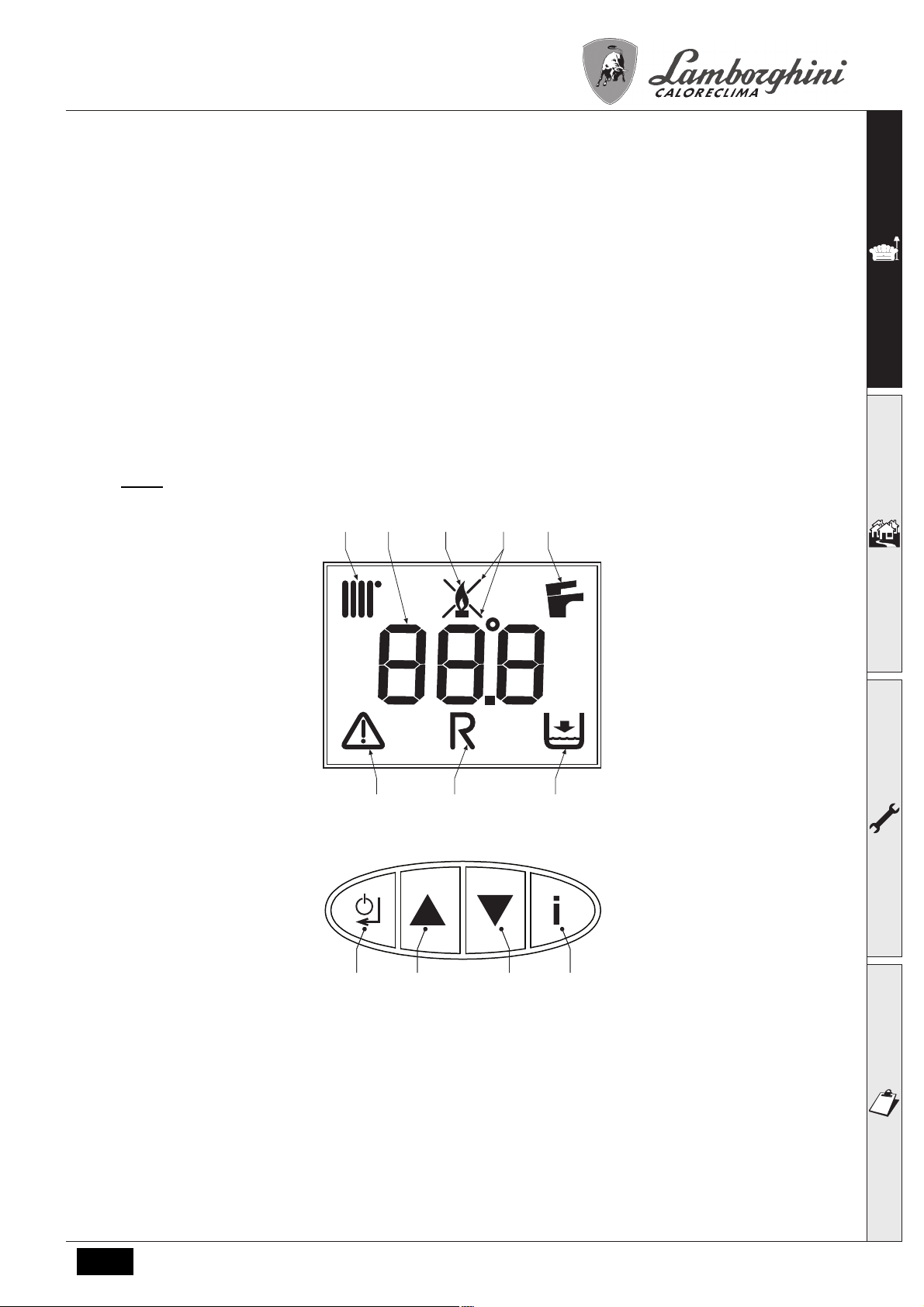
1.2 Control panel
Panel
1 Heating mode
2 Fault
3a Burner lit
3b Shutdown Fault
4 Multifunction
5 Pellet Loading Request in progress
6 DHW mode
7 System Filling Request
fig. 1 - Control panel
8 Reset – Enter – On/Off button
9 Parameter selection button
10
11 Menu Access – Information button
cod. 3541S060 - Rev. 00 - 05/2019
Pellet Loading Function – Parameter selection button
29EN
ECO P N
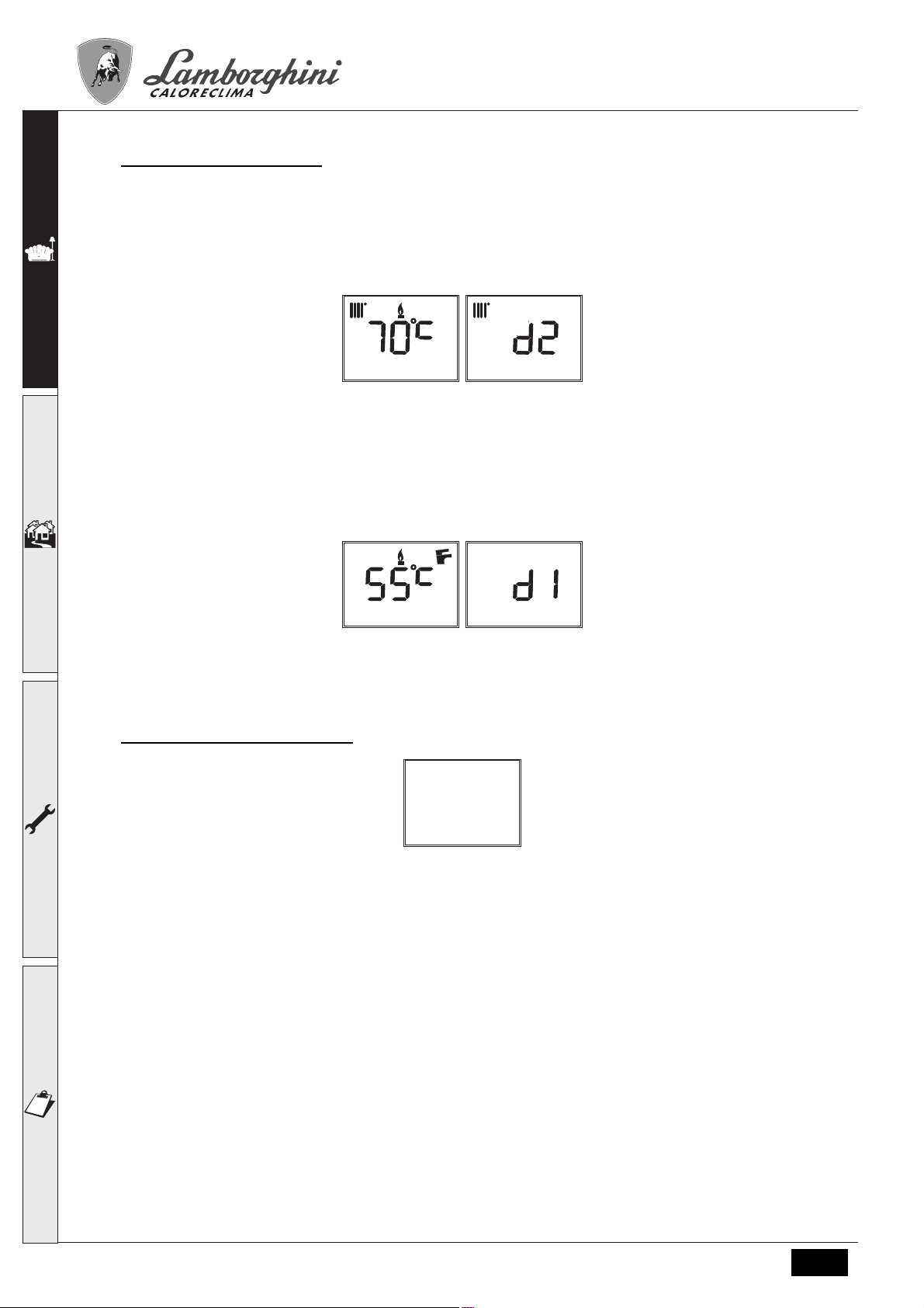
Indication during operation
Heating
A heating demand (generated by Request Contact, Room Thermostat or Remote Timer Control) is indicated by activation of the radiator (detail 1 - fig. 1).
The multifunction display (detail 4 - fig. 1) shows the heating sensor temperature and, during heating standby time, the
message “d2”.
fig. 2
Domestic hot water (DHW)
A DHW demand (generated by drawing hot water) is indicated by activation of the faucet (detail 6 - fig. 1).
The multifunction display (detail 4 - fig. 1) shows the DHW sensor temperature and, during DHW standby time, the mes-
sage “d1“.
1.3 Lighting and shutdown
Burner not electrically powered
fig. 4 - Burner not electrically powered
The frost protection system does not work when the power and/or gas to the unit are turned off. To avoid dam-
B
age caused by freezing during long shutdowns in winter, it is advisable to drain all water from the boiler, the
DHW circuit and the heating system water; or drain just the DHW circuit and add a suitable antifreeze to the
heating system, as prescribed in sec. 1.3.
fig. 3
30 EN
cod. 3541S060 - Rev. 00 - 05/2019
ECO P N
A
B
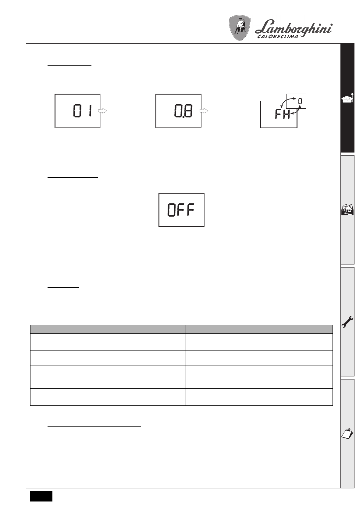
Burner ignition
Switch on the power to the burner.
•For the next 180 seconds the display will show 0/FH which identifies the heating system air venting cycle.
•During the first 10 seconds the display also shows the software version of the cards (A = Display card software version
/ B = Controller software version).
•When the message FH disappears, the burner is ready to work automatically whenever there is a room thermostat demand.
Burner shutdown
Press the on/off button (detail 8 - fig.1) for 5 seconds.
When the device is turned off, the PCB is still powered. Domestic hot water and heating are disabled. The frost protection system remains activated. To switch the device on again, press the on/off button (detail 8 - fig.1) for 5 seconds.
The device will be immediately ready to work whenever domestic hot water is drawn or in case of a heating demand
(generated by the Room Thermostat or Remote Timer control).
1.4 Adjustments
User menu
To access the user settings menu, press the Info button (detail 11 - fig. 1).
7 parameters and information indicated by the letter “u”are available.
Table. 1
Parameters User settings Range Default
u01 Heating adjustment temperature 30-80°C 80°C
u02 DHW adjustment temperature 10-65°C 65°C
u03 Summer/Winter selection 0 = Summer
1 = Winter
u04 Economy/Comfort selection 0 = Economy
1 = Comfort
u05 Burner max. power 1=Min, 5=Max 3
u06 Burner operation methodology 0=request contact, 1, 2 0=request contact
u07 Burner power (Step) and Flame status 0-6 -
1 = Winter
0 = Economy
By pressing the Info button it is possible to scroll the list of user settings, only in ascending order, until exiting the menu.
Heating temperature adjustment
Press the Info button (detail 11 - fig. 1) until displaying the parameter u01 of the user settings menu.
Press Enter (detail 8 - fig. 1): the actual value of the parameter u01 is displayed.
Use the buttons (details 9 and 10 - fig. 1) to adjust the temperature from a min. of 30°C to a max. of 85°C.
Press Enter (detail 8 - fig. 1) to confirm the setting.
Then press the Info button (detail 11 - fig. 1) until exiting the menu.
cod. 3541S060 - Rev. 00 - 05/2019
31EN
ECO P N
DHW temperature adjustment
Press the Info button (detail 11 - fig. 1) until displaying the parameter u02 of the user settings menu.
Press Enter (detail 8 - fig. 1): the actual value of the parameter u02 is displayed.
Use the buttons (details 9 and 10 - fig. 1) to adjust the temperature from a min. of 10°C to a max. of 65°C.
Press Enter (detail 8 - fig. 1) to confirm the setting.
Then press the Info button (detail 11 - fig. 1) until exiting the menu.
Summer/Winter Switchover
Press the Info button (detail 11 - fig. 1) until displaying the parameter u03 of the user settings menu.
Press Enter (detail 8 - fig. 1): the actual value of the parameter u03 is displayed.
Use the buttons (details 9 and 10 - fig. 1) to set Summer mode (0) or Winter mode (1).
Press Enter (detail 8 - fig. 1) to confirm the setting.
Then press the Info button (detail 11 - fig. 1) until exiting the menu.
ECO/COMFORT selection
Heating/hot water tank temperature maintaining (Comfort) can be excluded by the user.
If excluded (Economy), domestic hot water will not be delivered.
Press the Info button (detail 11 - fig. 1) until displaying the parameter u04 of the user settings menu.
Press Enter (detail 8 - fig. 1): the actual value of the parameter u04 is displayed.
Use the buttons (details 9 and 10 - fig. 1) to set Economy (0) or Comfort (1) mode.
Press Enter (detail 8 - fig. 1) to confirm the setting.
Then press the Info button (detail 11 - fig. 1) to exit the menu.
Burner Max. Power
Press the Info button (detail 11 - fig. 1) until displaying the parameter u05 of the user settings menu.
Press Enter (detail 8 - fig. 1): the actual max power step is displayed.
Use the buttons (details 9 and 10 - fig. 1) to vary the max power: from 1 (min Step) to 5 (max Step).
Table. 2 Burner max. power
Parameter value ECO 3,4 P N
Power - kW
1 14 30
2 20 36
3 25 41
4 30 48
5 34 55
Press Enter (detail 8 - fig. 1) to confirm the setting.
Then press the Info button (detail 11 - fig. 1) to exit the menu
ECO 5,5 P N
Power - kW
Burner operation methodology
Press the Info button (detail 11 - fig. 1) until displaying the parameter u06 of the user settings menu.
Press Enter (detail 8 - fig. 1): the actual value of the parameter u06 is displayed.
Use the buttons (details 9 and 10 - fig. 1) to vary the operation methodology:
•u06=0 (default): Burner activation with request contact (230Vac) or with Room Thermostat contact (voltage-free). (Re-
mote Control request by-passed).
•u06=1: Burner activation from Remote Control or with request contact (230Vac).
•u06=2: Burner activation from Remote Control and with request contact (230Vac).
Press Enter (detail 8 - fig. 1) to confirm the setting.
Then press the Info button (detail 11 - fig. 1) to exit the menu.
32 EN
cod. 3541S060 - Rev. 00 - 05/2019
ECO P N
Actual burner power (Step) and Flame status
Press the Info button (detail 11 - fig. 1) until displaying the information u07 of the user settings menu.
Press Enter (detail 8 - fig. 1): the actual burner power (Step) and Flame status are displayed.
•1 = Minimum Power
•5 = Maximum power
•0/FH = During Pre-ventilation/Post-ventilation
•6 = During Post-ventilation2
Press Enter (detail 8 - fig. 1) to return to the list of parameters.
Then press the Info button (detail 11 - fig. 1) to exit the menu.
Room temperature adjustment (with optional room thermostat)
Using the room thermostat, set the temperature required in the rooms. If the room thermostat is not installed, the boiler
will keep the system at the set system delivery setpoint temperature.
Room temperature adjustment (with optional remote timer control)
Using the remote timer control, set the required temperature in the rooms. The burner will adjust the system water according to the required room temperature. For operation with remote timer control, refer to the relevant instruction manual.
Adjustments from Remote Timer Control
A
If the Remote Timer Control (optional) is connected to the burner, the parameter “u06” must be modified (see
*** 'Burner operation methodology' on page 32 ***); the previously described adjustments are managed as described in table 3.
Table. 3
Heating temperature adjustment Adjustment can be made from the Remote Timer Control menu and the burner control panel.
DHW temperature adjustment Adjustment can be made from the Remote Timer Control menu and the burner control panel.
Summer/Winter Switchover Summer mode has priority over a possible Remote Timer Control heating demand.
Eco/Comfort selection Selection can only be made from the burner control panel
Burner shutdown (off) Off mode can only be done from Remote Timer Control.
cod. 3541S060 - Rev. 00 - 05/2019
33EN
 Loading...