

LAMBORGHINI ECO 50/2, ECO 70/2 Installation And Maintenance Manual
AZIENDA CERTIFICATA ISO 9001
MANUALE DI
INSTALLAZIONE E
MANUTENZIONE
INSTALLATION AND
MAINTENANCE
MANUAL
ECO 50/2 - ECO 70/2
NOTICE
D’INSTALLATION
ET D’ENTRETIEN
BRUCIATORE DI GASOLIO A DUE FIAMME
BRULEUR A GAZ A DEUX FLAMMES
QUEMADORES A GAS CON DOS LLAMAS
∫∞À™∆∏ƒ∂™ ¶∂∆ƒ∂§∞π√À ª∂ ¢À√ º§√°∂™
INSTALLATIONS-
UND
WARTUNGSANLEITUNG
LIGHT OIL BURNERS
ZWEIFLAMMIGE GASBRENNER
MANUAL PARA LA
INSTALACIÓN Y EL
MANTENIMIENTO
∂°Ã∂πƒπ¢π√
∂°∫∞∆∞™∆∞™∏™
∫∞π ™À¡∆∏ƒ∏™∏™


ITALIANO
4
Leggere attentamente le istruzioni ed avvertenze contenute sul presente libretto in quanto
forniscono importanti indicazioni riguardanti la sicurezza d’installazione, d’uso e di manutenzione. Conservare con cura questo libretto per ogni ulteriore consultazione.
L’installazione deve essere effettuata da personale qualificato che sarà responsabile del
rispetto delle norme di sicurezza vigenti.
ENGLISH
FRANÇAIS
DEUCHT
ESPAÑOL
22
Please read the instructions and warnings in this document carefully as there is important
information regarding installation, use and maintenance. Keep the manual in a safe place
for future reference. The installation must be carried out by qualified personnel that will be
responsible for conformance with current safety regulations in force.
40
Lire attentivement les instructions et les avertissements contenus dans ce manuel, car ils
proportionnent d’importantes indications concernant la sécurité de montage, d’emploi et
d’entretien. Garder avec soin ce manuel pour toute autre consultation. Seulement le personnel
qualifié, qui sera responsable du respect des lois de sécurité en vigeur, peut réaliser le
montage.
58
Die in dieser Anleitung enthaltenen Anweisungen und Hinweise lesen, da sie wichtige
Angaben zur Sicherheit, Verwendung und Wartung liefern. Das Handbuch ist zum
Nachschlagen sorgfältig aufzubewahren. Die Installation muss von qualifiziertem Personal vorgenommen werden, das für die Einhaltung der geltenden Sicherheitsvorschriften
verantwortlich ist.
76
Leer detenidamente las instrucciones y advertencias contenidas en el presente manual por
cuanto ofrecen importantes indicaciones que se refieren a la seguridad de instalación, de
uso y de mantenimiento. Tratar este manual con delicadeza y conservarlo en un lugar
seguro para poder consultarlo cada vez que sea necesario. La instalación deberá ser
realizada p or personal capacitado y calificado, que tendrá asimismo la responsabilidad
de respetar la normativa vigente sobre seguridad.
∂§§∏¡π∫∞
94
¢И·‚¿ЫЩВ ЪФЫВОЩИО¿ ЩИ˜ Ф‰ЛБ›В˜ О·И ЩИ˜ ЪФВИ‰ФФИ‹ЫВИ˜ Ф˘ ВЪИ¤¯ФУЩ·И ЫЩФ ·ЪfiУ
ВБ¯ВИЪ›‰ИФ ·КФ‡ ·Ъ¤¯Ф˘У ЫЛМ·УЩИО¤˜ ˘Ф‰В›НВИ˜ Ы¯ВЩИО¤˜ МВ ЩЛУ ·ЫК¿ПВИ·
ВБО·Щ¿ЫЩ·ЫЛ˜, ¯Ъ‹ЫЛ˜ О·И Ы˘УЩ‹ЪЛЫЛ˜. º˘П¿НЩВ ЪФЫВОЩИО¿ ЩФ ВБ¯ВИЪ›‰ИФ, ТЫЩВ
У· МФЪВ›ЩВ У· ·У·ЩЪ¤НВЩВ ЫВ ·˘Щfi ЫЩФ М¤ППФУ.
∏ ВБО·Щ¿ЫЩ·ЫЛ Ъ¤ВИ У· ‰ИВУВЪБЛıВ› ·fi ВИ‰ИОВ˘М¤УФ ЪФЫˆИОfi Ф˘ ı· В›У·И
˘В‡ı˘УФ БИ· ЩЛУ Щ‹ЪЛЫЛ ЩˆУ ИЫ¯˘fiУЩˆУ О·УФУИЫМТУ ·ЫК·ПВ›·˜.

INDICE PAGINA
NORME GENERALI ______________________________________________________________5
DESCRIZIONE __________________________________________________________________ 7
DIMENSIONI mm _______________________________________________________________ 7
CARATTERISTICHE TECNICHE _____________________________________________________ 8
CURVE DI LAVORO______________________________________________________________ 8
MONTAGGIO ALLA CALDAIA ____________________________________________________ 9
DIMENSIONI FIAMMA ___________________________________________________________ 9
COLLEGAMENTI ELETTRICI ______________________________________________________10
ALIMENTAZIONE GASOLIO _____________________________________________________11
ALIMENTAZIONE MONOTUBO __________________________________________________ 11
ALIMENTAZIONE BITUBO _______________________________________________________ 11
SCELTA UGELLO _______________________________________________________________ 12
ESEMPIO SCELTA UGELLO _______________________________________________________ 12
MONTAGGIO UGELLO _________________________________________________________ 12
POSIZIONAMENTO ELETTRODI-DEFLETTORE _______________________________________13
CICLO FUNZIONAMENTO ______________________________________________________ 13
DIAGNOSI DELLA CAUSA DEL DIFETTO LMO 44____________________________________ 14
REGOLAZIONE TESTA __________________________________________________________15
REGOLAZIONE ARIA DI COMBUSTIONE __________________________________________ 15
MESSA IN FUNZIONE __________________________________________________________16
REGOLAZIONE PRESSIONE POMPA ______________________________________________ 17
CONTROLLO COMBUSTIONE ___________________________________________________17
MANUTENZIONE ______________________________________________________________ 18
FOTORESISTENZA _____________________________________________________________18
FILTRO POMPA ________________________________________________________________ 18
FILTRO DI LINEA _______________________________________________________________ 18
POSIZIONE VENTOLA __________________________________________________________18
ELETTRODI-UGELLO ____________________________________________________________ 19
IRREGOLARITA’ DI FUNZIONAMENTO ____________________________________________ 20
4
Complimenti...
...Per l'ottima scelta. La ringraziamo per la preferenza accordata ai ns. prodotti.
LAMBORGHINI CALORECLIMA è da 1959 attivamente presente in Italia e nel mondo con una rete capillare
di Agenti e concessionari, che garantiscono costantemente la presenza del prodotto sul mercato.
Si affianca a questo un servizio di assistenza tecnica, «LAMBORGHINI SERVICE», al quale è affidata una
qualificata manutenzione del prodotto.
Per l’ìinstallazione e per il posizionamento della caldaia:
RISPETTARE SCRUPOLOSAMENTE LE NORME LOCALI VIGENTI

NORME GENERALI
● Il presente libretto costituisce parte integrante ed essenziale del prodotto e dovrà essere consegnato
all’installatore.
Leggere attentamente le avvertenze contenute nel presente libretto in quanto forniscono importanti
indicazioni riguardanti la sicurezza d’installazione, d’uso e manutenzione.
Conservare con cura questo libretto per ogni ulteriore consultazione. L’installazione del bruciatore deve
essere effettuata in ottemperanza alle norme vigenti, secondo le istruzioni del costruttore e da
personale qualificato. Un’errata installazione può causare danni a persone, animali o cose, per i quali il
costruttore non è responsabile.
● Questo apparecchio dovrà essere destinato solo all’uso per il quale è stato espressamente previsto.
Ogni altro uso è da considerarsi improprio e quindi pericoloso.
Il costruttore non può essere considerato responsabile per, eventuali danni causati da usi impropri,
erronei ed irragionevoli.
● Prima di effettuare qualsiasi operazione di pulizia o di manutenzione, disinserire l’apparecchio dalla rete
di alimentazione o agendo sull’interruttore dell’impianto o attraverso gli appositi organi di
intercettazione.
● In caso di guasto e/o di cattivo funzionamento dell’apparecchio, disattivarlo, astenendosi da qualsiasi
tentativo di riparazione o di intervento diretto.
Rivolgersi esclusivamente a personale professionalmente qualificato.
L’eventuale riparazione dei prodotti dovrà essere effettuata solamente da un centro di assistenza
autorizzato dalla casa costruttrice utilizzando esclusivamente ricambi originali.
Il mancato rispetto di quanto sopra può compromettere la sicurezza dell’apparecchio.
Per garantire l’efficienza dell’apparecchio e per il suo corretto funzionamento è indispensabile
attenersi alle indicazioni del costruttore, facendo effettuare da personale professionalmente qualificato, la
manutenzione periodica dell’apparecchio.
● Allorché si decida di non utilizzare più l’apparecchio, si dovranno rendere innocue quelle parti che
possono diventare potenziali fonti di pericolo.
● Prima di avviare il bruciatore far verificare da personale qualificato:
a) che i dati di targa siano quelli richiesti dalla rete di alimentazione gas elettrica;
b) che la taratura del bruciatore sia compatibile con la potenza della caldaia;
c) che l’afflusso di aria comburente e l’evacuazione dei fumi avvengano correttamente secondo le
norme vigenti;
d) che siano garantite l’aerazione e la normale manutenzione del bruciatore.
● Prima di effettuare qualsiasi intervento che preveda lo smontaggio del bruciatore o l’apertura di
accessi di ispezione, disinserire la corrente elettrica e chiudere i rubinetti del gas.
● Non depositare contenitori con sostanze infiammabili nel locale ove è situato il bruciatore.
● Il locale del bruciatore deve possedere delle aperture verso l’esterno conformi alle norme locali in
vigore. In caso di dubbio relativamente alla circolazione dell’aria, ci raccomandiamo di misurare anzi
tutto il valore del CO2, con il bruciatore funzionante alla sua massima portata ed il locale ventilato,
solamente tramite le aperture destinate ad alimentare d’aria il bruciatore; poi, misurando il valore di
CO2, una seconda volta, con la porta aperta. Il valore del CO2 misurato in entrambi i casi non deve
cambiare in maniera significativa. In caso si trovassero più di un bruciatore e di un ventilatore nello
stesso locale, questo test deve essere effettuato con tutti gli apparecchi funzionanti contemporaneamente.
5

● Non ostruire mai le aperture dell’aria del locale del bruciatore, le aperture di aspirazione del
ventilatore del bruciatore ed un qualsiasi condotto dell’aria o griglie di ventilazione e di dissipazione
esistenti, allo scopo di evitare:
-la formazione di miscele di gas tossiche/esplosive nell’aria del locale del bruciatore;
-la combustione con aria insufficiente, dalla quale ne deriva un funzionamento pericoloso, costoso
ed inquinante.
● Il bruciatore deve essere sempre protetto dalla pioggia, dalla neve e dal gelo.
● Il locale del bruciatore deve essere sempre mantenuto pulito e libero da sostanze volatili, che
potrebbero venire aspirate all’interno del ventilatore ed otturare i condotti interni del bruciatore o
della testa di combustione. La polvere è estremamente dannosa, particolarmente se vi è la possibilità
che questa si posi sulle pale del ventilatore, dove andrà a ridurre la ventilazione e produrrà
inquinamento durante la combustione. La polvere può anche accumularsi sulla parte posteriore del
disco di stabilità fiamma nella testa di combustione e causare una miscela povera aria-combustibile.
● Il bruciatore deve essere alimentato con il tipo di combustibile per il quale è stato predisposto come
indicato sulla targhetta con i dati caratteristici e nelle caratteristiche tecniche fornite in questo manuale.
La linea del combustibile che alimenta il bruciatore deve essere perfettamente a tenuta, realizzato in modo
rigido. Inoltre dovrà essere dotata di tutti i meccanismi di controllo e sicurezza richiesti dai
regolamenti locali vigenti. Prestare particolare attenzione al fatto che nessuna materia esterna entri
nella linea durante l’installazione.
● Assicuratevi che l’alimentazione elettrica utilizzata per il collegamento sia conforme alle
caratteristiche indicate nella targhetta dei dati caratteristici ed in questo manuale.
Il bruciatore deve essere correttamente collegato ad un sistema efficiente di terra, in conformità alle norme
vigenti. In caso di dubbio riguardo all’efficienza, deve essere verificato e controllato da
personale qualificato.
● Non scambiare mai i cavi del neutro con i cavi della fase.
● Il bruciatore può essere allacciato alla rete elettrica con un collegamento spina-presa, solamente se
questo risulti dotato in modo tale per cui la configurazione dell’accoppiamento prevenga l’inversione
della fase e del neutro. Installare un interruttore principale sul quadro di controllo, per l’impianto di
riscaldamento, come richiesto dalla legislazione esistente.
● L’intero sistema elettrico e in particolare tutte le sezioni dei cavi, devono essere adeguati al valore
massimo di potenza assorbita ed indicato sulla targhetta dei dati caratteristici dell’apparecchio e su
questo manuale.
● Se il cavo di alimentazione del bruciatore risulta difettoso, deve essere sostituito solamente da
personale qualificato.
● Non toccare mai il bruciatore con parti del corpo bagnate oppure senza indossare scarpe.
● Non stirare (forzare) mai i cavi di alimentazione e mantenerli distanti da fonti di calore.
● La lunghezza dei cavi utilizzati deve consentire l’apertura del bruciatore ed eventualmente della porta
della caldaia.
● I collegamenti elettrici devono essere effettuati esclusivamente da personale qualificato e devono
essere scrupolosamente rispettate le regolamentazioni vigenti in materia di elettricità.
● Dopo aver tolto tutti i materiali d’imballo, controllare i contenuti ed assicuratevi che questi non siano stati
in alcun modo danneggiati durante il trasporto.
In caso di dubbio, non utilizzare il bruciatore e contattare il fornitore.
I materiali di imballo (gabbie di legno, cartone, borse di plastica, espanso, graffe, ecc...) rappresentano
una forma di inquinamento e di potenziale rischio, se lasciati giacenti ovunque; quindi occorre raggrup
parli insieme e disporli in maniera adeguata (in un luogo idoneo).
6
DESCRIZIONE
Sono bruciatori di gasolio a polverizzazione meccanica. Il percorso dell’aria è stato studiato per ottenere dal
ventilatore una curva di lavoro ad alta pressione con un flusso uniforme e lineare. Il dosaggio dell’aria di
combustione è realizzato con una doppia regolazione: una sulla linea dell’ugello, con spostamento del disco
deflettore su una testa tronco conica, e un’altra con serranda parzializzatrice sulla mandata della ventola.
Questo sistema permette di ottenere sempre le migliori condizioni di pressione/portata aria in tutto il campo
di lavoro del bruciatore per realizzare combustioni a basso eccesso d’aria, ad alto rendimento e ad alta di
energia miscelazione con basso contenuto d’inquinanti, CO e NOx. La serranda dell’aria è a chiusura totale,
all’arresto, per limitare le dispersioni di calore dalla caldaia durante le soste; è motorizzata con servocomando elettrico a tre posizioni, chiuso-aperto prima fiamma-aperto seconda fiamma.
Tutti i componenti sono protetti da un elegante cofano che effettua, anche, una buona insonorizzazione. Il
funzionamento è automatico, con sorveglianza della fiamma a sonda a fotoresistenza; la pompa è
autoaspirante, a uno-due tubi, con by-pass e valvola elettromagnetica incorparata. I bruciatori sono ad
ispezionabilità totale, rendendo facili e rapide le operazioni di controllo e manutenzione.
Tipi ECO 50/2 e ECO 70/2 a due ugelli, con avviamento a portata ridotta e funzionamento “alta/bassa
fiamma”.
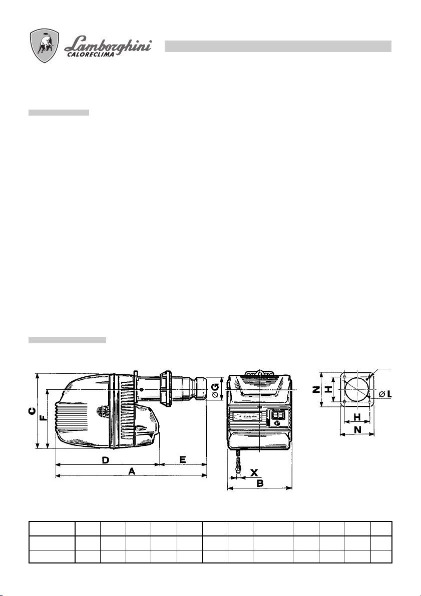
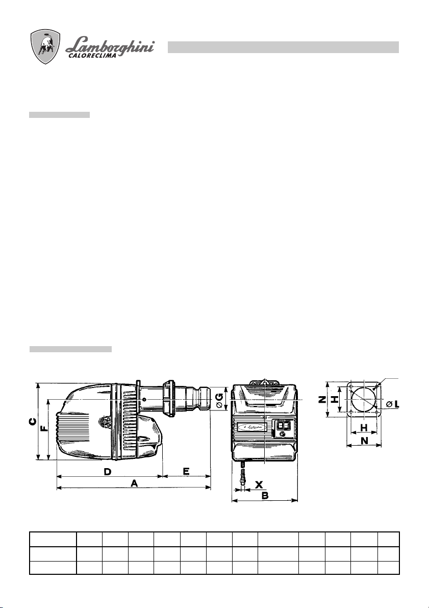
DIMENSIONI mm.
7
Modello
ECO 50/2
ECO 70/2
Ø
ABCDEFØ GH LNXø
1040 420 490 655 385 392 140 121÷160 150 200 3/8” M10
1080 420 490 695 385 392 170 160÷200 180 230 3/8” M14
CARATTERISTICHE TECNICHE
POTENZA kW
ECO 50/2
PRESSIONE FOCOLARE (mbar)
MODELLO ECO 50/2 ECO 70/2
Potenza termica min. kW 177 197
max. kW 585 776
min. kcal/h 152.300 169.000
max. kcal/h 503.200 667.600
Consumo combustibile min. Kg/h (15) - 21,4 (16,6) - 27
max. Kg/h 49,3 65,4
Pompa combustibile bar 12 12
Combustibile gasolio p.c.i. 10200 (6cst) a 20°C
Peso kg 55 59
Motore W 1.100 1.500
Protettore Termico A 2,7-4,4 2,7-4,4
Trasformatore d’accensione kV/mA 12/35 12/35
Alimentazione elettrica 230/400V - 50 Hz trifase
Potenza totale assorbita W 1.500 1.900
Apparecchiatura di controllo fiamma Elettronica c/fotores. Elettronica c/fotores.
Regolazione aria Motorizzata Motorizzata
Numero stadi 2 2
N.B.: I dati riportati fra parentesi si riferiscono alla minima portata ottenibile con la 1a fiamma.
kcal/kg1,50°E
8
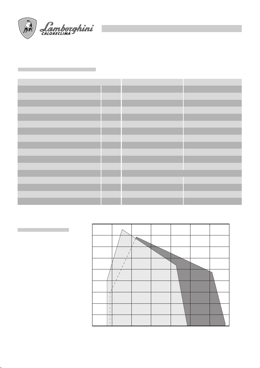
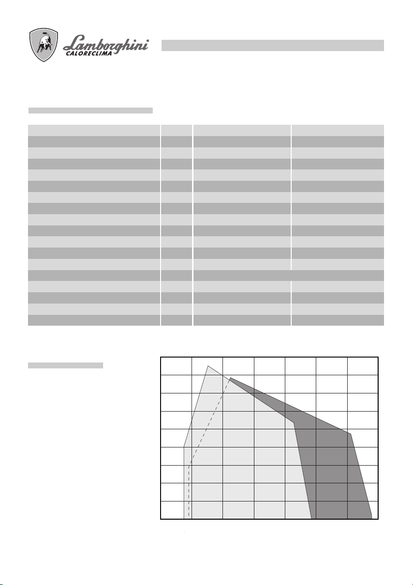
CURVE DI LAVORO
9
8
7
6
5
4
3
2
1
0
100 200 300 400 500 600 700 800
ECO 70/2
Indicano la potenza in kW, in funzione della contropressione, in mbar, in camera di combustione.
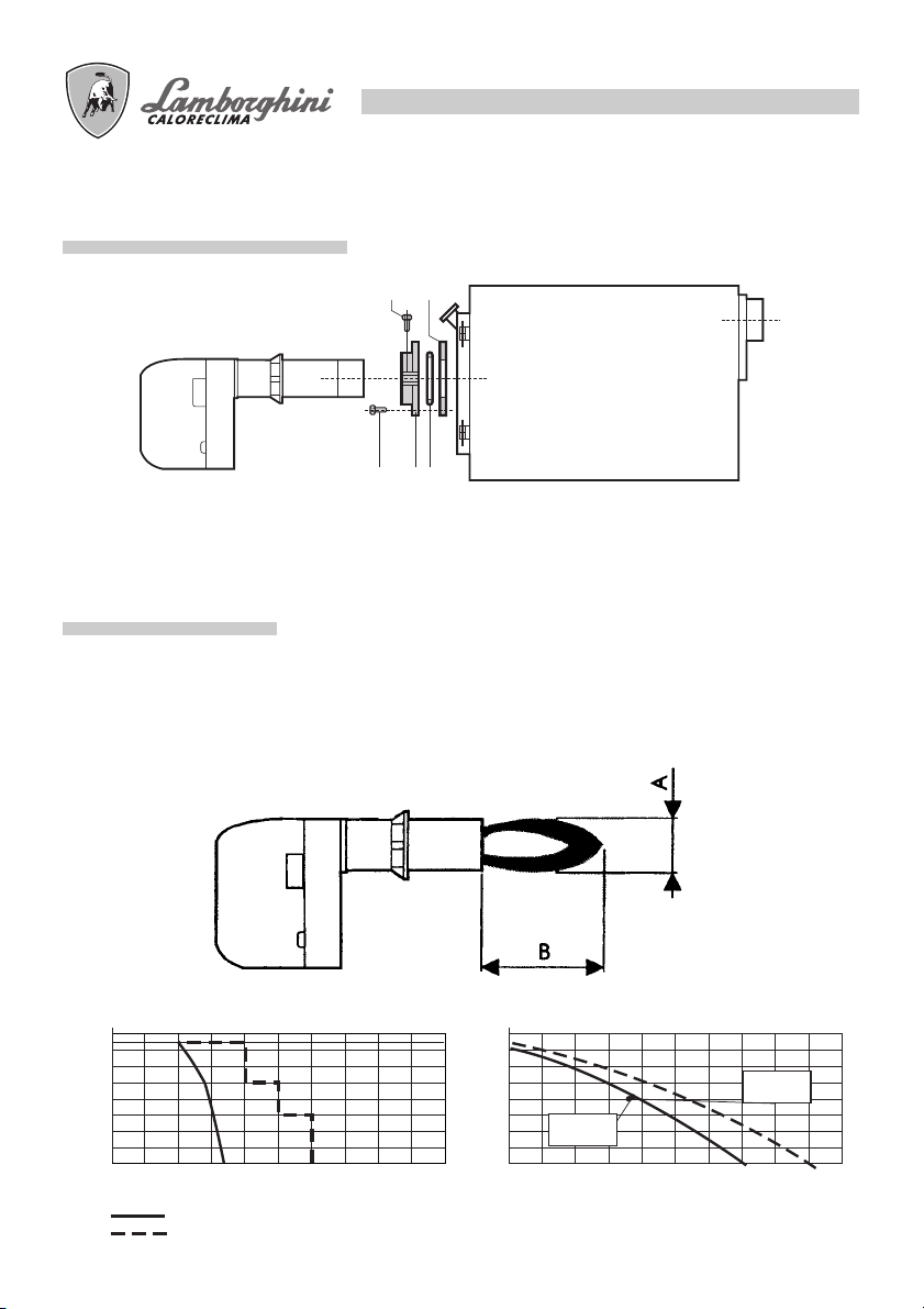
MONTAGGIO ALLA CALDAIA
1 4
3 2 5
Fissare la flangia 2 alla caldaia con n° 4 viti 3 interponendo la guarnizione isolante 4 e l’eventuale corda
isolante 5. Infilare il bruciatore nella flangia in modo che il boccaglio penetri nella camera di combustione
secondo le indicazioni del costruttore della caldaia. Stringere la vite 1 per bloccare il bruciatore.
DIMENSIONI FIAMMA
Le dimensioni sono orientative essendo influenzate da:
● eccesso di aria
● forma camera di combustione
● sviluppo giri fumo della caldaia (diretto/rovesciamento)
● pressione in camera di combustione.
9
Mcal/h
200
400
600
800
Diametro fiamma Lunghezza fiamma
0
D = 50
D = 60
10 20 30 40 50 60 70 80 90
fiamma
tubo prova
100
218 M cal
115 cm
667 M cal
200 cm
180 200 220 240120 140 160100806040
cm
10
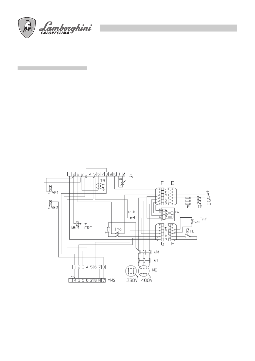
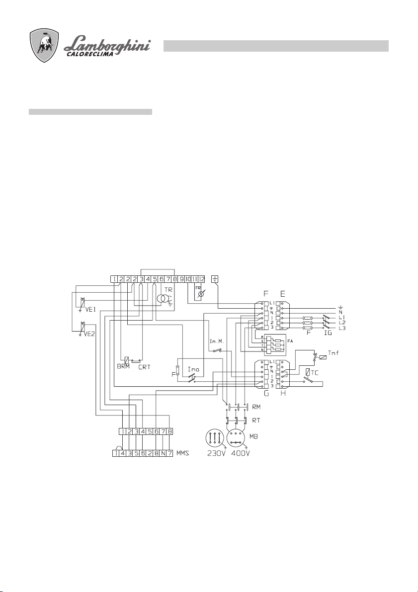
COLLEGAMENTI ELETTRICI
I collegamenti da effettuare a cura dell’installatore sono:
● linea di alimentazione
● linea termostatica
● eventuale lampada di blocco
● eventuale contaore
● eventuale termostato modulazione fiamma
(togliere il cavo che ponticella)
N.B.: È necessario osservare scrupolosamente la buona norma che indica il collegamento di massimo due
cavi per morsetto.
Attenzione:
● non scambiare il neutro con la fase
● eseguire un buon collegamento di terra
● rispettare le norme della buona tecnica ed osservare
scrupolosamente le norme locali vigenti
LEGENDA
BRM Bobina relè motore
CRT Contatto relè termico
F Fusibile
FA Filtro antidisturbo
FR Fotoresistenza
IG Interruttore generale
Ima Interruttore marcia arresto
ImM Interruttore min Max
MB Motore bruciatore
MMS Morset.motorino servocomando aria
MPE Morset. apparecc. Landis LOA 44/LMO 44
RM Relè motore
RT Relè termico
TMF Te rmostato modulazione 2° fiamma (event.)
TP Te mporizzatore
TR Trasformatore
TS Te rmostato di sicurezza
VE1 Va lvola elettromagnetica 1° fiamma
VE2 Va lvola elettromagnetica 2° fiamma

11
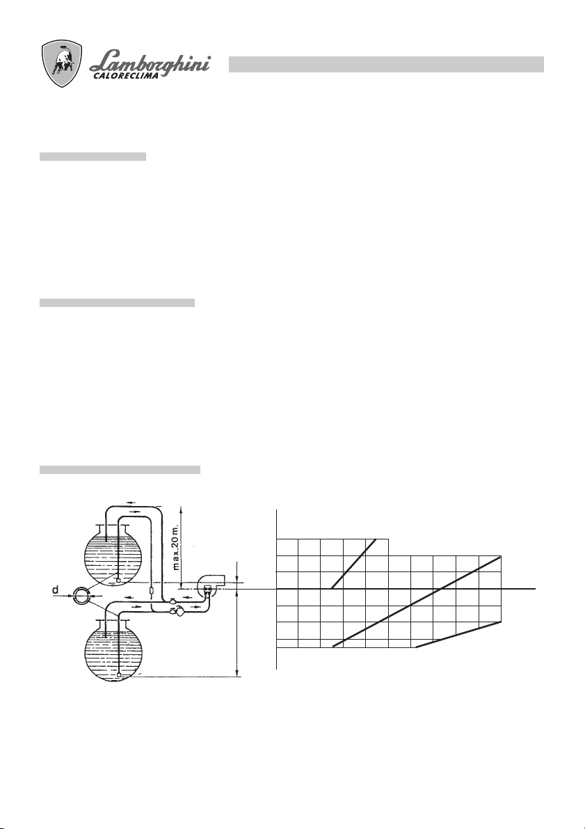
ALIMENTAZIONE GASOLIO
Le dimensioni delle tubazioni (diametro/lunghezza) sono in relazione con il tipo di impianto (a uno/due tubi,
in aspirazione/caduta) e con le caratteristiche della pompa.
Il diagramma, indica la massima lunghezza L consentita di una linea di aspirazione in funzione del dislivello
H e del diametro interno del tubo d, per una pressione atmosferica di 1013 mbar ed un vuoto di 0,45 bar e
considerando il montaggio di 4 gomiti, di una valvola di blocco ed una di non ritorno.
ALIMENTAZIONE MONOTUBO
Si raccomanda di evitare, per quanto possibile, questa soluzione poichè è noto che essa può originare
notevoli disfunzioni al bruciatore se non è realizzata in modo perfetto. Se, tuttavia, non è possibile evitare
questa installazione, si tenga presente: eseguire solo impianti a caduta; modificare la pompa togliendo il
grano interno; prevedere idonei spurghi dell’aria nei punti più alti della tubazione ed evitare il formarsi di
sacche d’aria.
ALIMENTAZIONE BITUBO
Hí
3
2
1
0
10 20 30 605040 908070 100
1
2
3
3,5
IN ASPIRAZIONE A CADUTA
H
Ø8
Ø10
L
Ø12
12
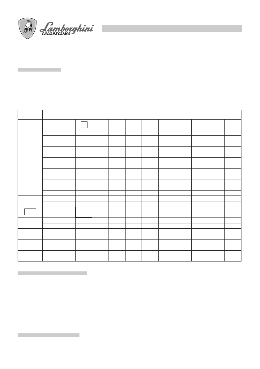
SCELTA UGELLO
La scelta va fatta in relazione alla potenza del focolare della caldaia, tenendo presente che il gasolio ha un
potere calorifico (P.C.I.) di 10200 kcal/kg. La tabella indica la portata teorica o consumo, in kg/h e in kW, di
gasolio in funzione della grandezza dell’ugello (GPH) e della pressione della pompa (in bar). Nei bruciatori
a due ugelli, la portata viene suddivisa, indicativamente, per il 40% sull’ugello di prima fiamma, e per il 60%
sul secondo ugello.
UGELLO
GPH
2,00
2,50
3,00
3,50
4,00
4,50
5,00
6,00
7,00
8,30
9,50
10,50
10 11 12 13 14 15 16 17 18 19 20 21
7,43 7,75 8,10 8,42 8,80 9,05 9,35 9,67 9,91 10,22 10,48 10,70
88,12 91,91 96,06 99,86 104,37 107,33 110,90 114,68 117,53 121,21 124,30 126,90
9,28 9,67 10,17 10,54 10,98 11,27 11,70 12,10 12,38 12,76 13,10 13,40
110,06 114,68 120,62 125,00 130,22 133,66 138,76 143,50 146,82 151,33 155,36 158,92
11,17 11,60 12,16 12,65 13,20 13,60 14,10 14,50 14,88 15,16 15,70 16,10
132,47 137,58 144,22 150,03 156,55 161,30 167,22 171,98 176,47 179,80 186,20 190,94
13,05 13,60 14,20 14,78 15,40 15,85 16,40 16,95 17,38 17,90 18,30 18,80
154,77 161,30 168,41 175,29 182,64 187,98 194,50 201,03 206,12 212,29 217,04 222,97
14,88 15,50 16,24 16,90 17,60 18,12 18,70 19,37 19,88 20,40 21,00 21,50
176,47 183,83 192,60 200,43 208,73 214,90 221,78 229,73 235,77 241,94 249,06 255,00
16,67 17,35 18,20 18,90 19,70 20,30 21,00 21,70 22,25 22,90 23,50 24,00
197,70 205,77 215,85 224,15 233,64 240,76 249,06 257,36 263,88 271,60 278,71 284,64
18,60 19,35 20,30 21,10 22,00 22,60 23,35 24,15 24,80 25,50 26,20 26,70
220,60 229,49 240,76 250,24 260,92 268,03 286,42 294,13 307,36 310,73 316,66
22,30 23,25 24,35 25,30 26,40 27,20
264,48 275,74 288,80 300,06 313,10 322,59
26,00 27,15 28,40 29,50 30,70 31,70
308,36 322,00 336,82 349,87 364,10 375,96
30,80 32,10 33,60 34,90 36,40 37,50
365,29 380,70 398,50 413,91 431,70 444,75
35,30 36,70 38,50 40
418,66 435,26 456,61 474,4
39,00 40,65
462,54 482,11
PRESSIONE POMPA bar (kg/cm2)
276,93
28,10
29,00 29,75 30,75 31,40 32,20
343,94 352,83 364,49 372,40 381,90
333,26
33,90 34,80 35,80 36,65 37,50
32,70
402,05 412,73 424,59 434,67 444,75
387,82
38,75
40,20
476,77
45957
ESEMPIO SCELTA UGELLO
La caldaia ha una potenza al focolare di 290 kW.
Per una pressione in pompa di 12 bar, il valore più vicino é kW 288,80 a cui corrisponde un ugello da 6 GPH.
Se il bruciatore è a due ugelli, dividere la portata con un ugello da 2,50 GPH sulla prima fiamma e da 3,50
GPH sulla seconda.
Se non si dispone dell’ugello ottimale si può, entro i limiti di 11 - 14 bar, variare la pressione della pompa per
ottenere la portata desiderata.
MONTAGGIO UGELLO
Una volta scelto l’ugello adatto, procedere al montaggio come indicato al paragrafo “MANUTENZIONE”.
13
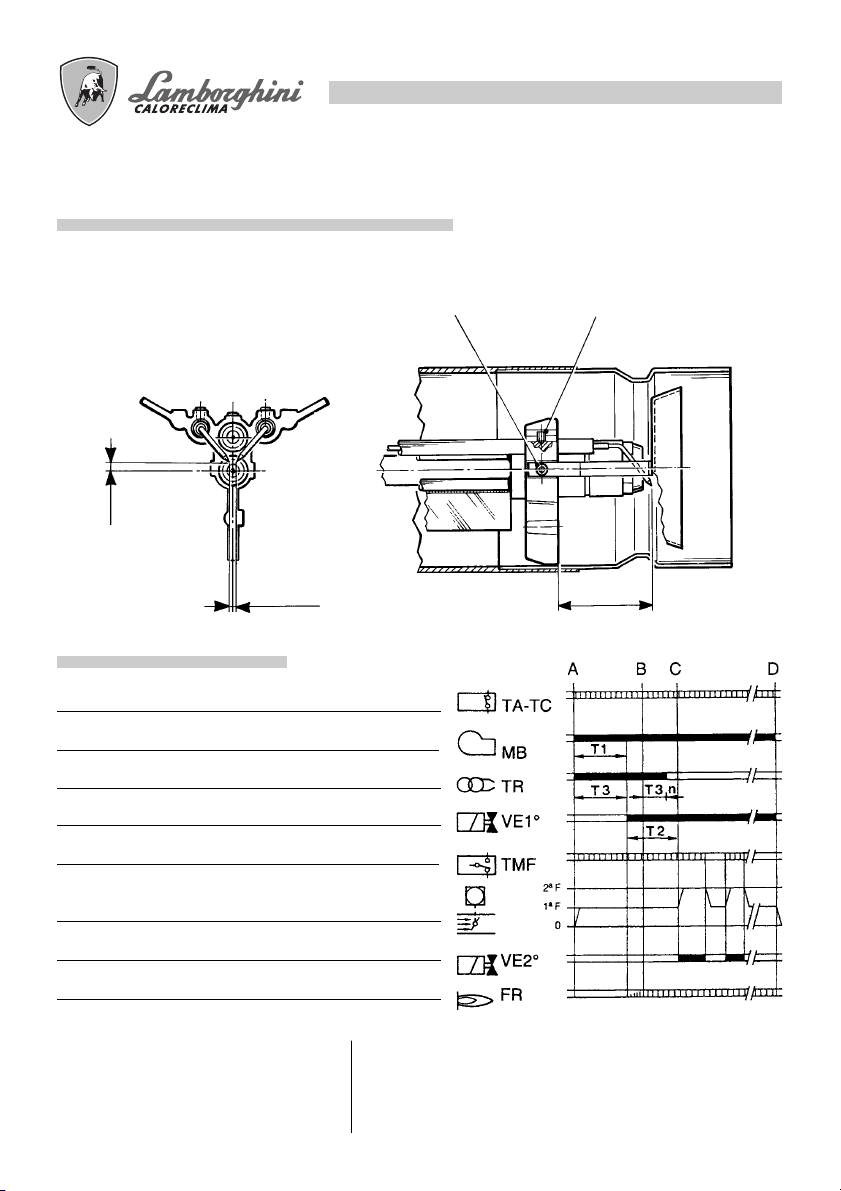
POSIZIONAMENTO ELETTRODI - DEFLETTORE
Dopo avere montato l’ugello (o gli ugelli), verificare il corretto posizionamento di elettrodi e deflettore, secondo le quote riportate (mm). È opportuno esguire una verifica delle quote dopo ogni intervento sulla testa.
- 1
5
0
5
6
- 0
4
+1
CICLO FUNZIONAMENTO
Termostato amb.-caldaia
Motore
Trasformatore
Valvola elettromagnetica 1° fiamma
Termostato modulazione
Servocomando aria
Valvola elettromagnetica 2° fiamma
Fotoresistenza
A - inizio avviamento
B - presenza di fiamma
C - fine avviamento
C-D - funzionamento normale
D - arresto di regolazione (TA-TC)
+0
65
+0,5
T1 tempo di preventilazione 25 sec. 26 sec.
T2 tempo di sicurezza 5 sec. 5 sec.
T3 tempo di preaccensione 25 sec. 25 sec.
T3n tempo di postaccensione 2 sec. 5 sec.
LOA 44 LMO 44

14
DIAGNOSI DELLA CAUSA DEL DIFETTO LMO 44
Dopo la messa in blocco la lampada rossa di indicazione di difetto LR rimane costantemente accesa.
In questa condizione, può essere attivata la diagnosi visiva della causa di difetto secondo la tabella codici
errore premendo il pulsante di sblocco PS per oltre 3 secondi.
Premendo nuovamente il pulsante di sblocco per almeno 3 secondi, viene attivata la diagnosi di interfaccia.
La seguente sequenza attiva la diagnosi della causa di difetto:
Tabella codici di errore
Codice lampeggiante Causa probabile
2 lampegggi Fiamma non stabilizzata alla fine del T2
•• Valvole combustibile difettose o sporche
3 lampeggi Libero
•••
4 lampeggi Luci estranee alla partenza del bruciatore
••••
5 lampeggi Libero
•••••
6 lampeggi Libero
••••••
7 lampeggi Troppe perdite di fiamma durante il funzionamento (limitazione delle ripetizioni)
••••••• Valvole combustibile difettose o sporche
8 lampeggi Tempo di controllo olio preriscaldatore
•••••••••
9 lampeggi Libero
•••••••••
10 lampeggi Errore di collegamento elettrico o errore interno, contatti uscita
••••••••••
Rivelatore di fiamma difettoso o sporco
Regolazione scarsa del bruciatore, mancanza di combustibile
Accensione difettosa
Rivelatore di fiamma difettoso o sporco
Regolazione scarsa del bruciatore
Durante il tempo la causa di difetto viene diagnosticata, le uscite di controllo sono disattivate.
- Il bruciatore rimane fermo
- Il segnale di stato di difetto LR viene attivato al terminale 10
La diagnosi della causa di difetto smette e il bruciatore viene nuovamente messo in funzione riarmando il
dispositivo di controllo del bruciatore.
Premere il pulsante di riarmo per circa 1 secondo (< 3 secondi).
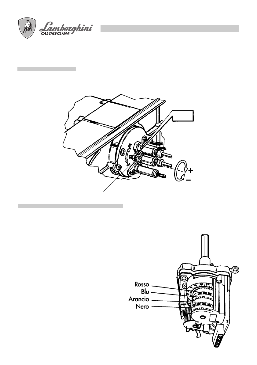
REGOLAZIONE TESTA
Agendo sulla vite A si modifica la posizione della linea ugello/deflettore rispetto al boccaglio, variando, di
conseguenza, la sezione di passaggio dell’aria.
ECO 50/2
ECO 70/2
A
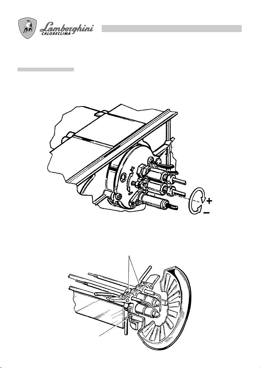
REGOLAZIONI ARIA DI COMBUSTIONE
15
La serranda aria è azionata dal motoriduttore.
La regolazione delle posizioni chiuso/aperto, 1a fiamma/aperto max., si effetua sulle camme girando in
senso antiorario per aumentare l’apertura della serranda ed in senso orario per diminuirla.
Camma blu Posizione chiusura totale
Camma arancio Regolazione aria 1a fiamma.
Camma rossa Regolazione aria 2a fiamma.
Camma nera Consenso apertura elettrovalvola
Servocomando tipo SQN 70...
della 2a fiamma.
MESSA IN FUNZIONE
1) OPERAZIONI PRELIMINARI
- montare il manometro ed il vuotometro sulla pompa (togliere dopo la messa a punto).
- aprire le saracinesche lungo la tubazione del gasolio.
- chiudere la linea dei termostati (caldaia/ambiente)
- dare corrente dall’interrutore generale
- porre in posizione di marcia l’interrutore
- sbloccare l’apparecchiatura (spingendo il pulsante rosso)
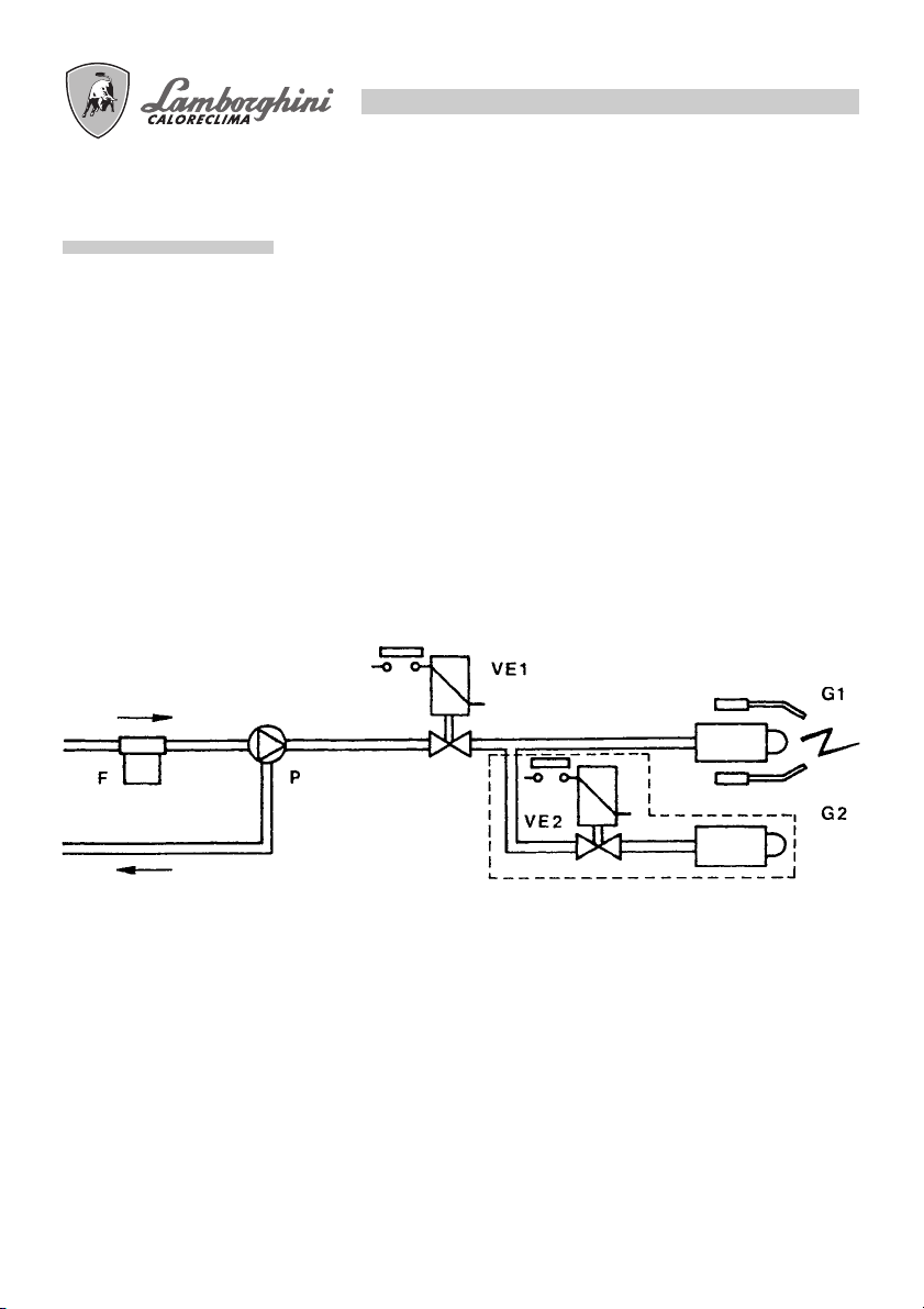
2) AVVIAMENTO
F- filtro di linea
P- pompa
VE1 - elettrovalvola 1° ugello
VE2 - elettrovalvola 2° ugello
G1 - 1° ugello
G2 - 2° ugello
16
A) Dopo le operazioni preliminari inizia il ciclo di avviamento. Il motore del bruciatore si mette in
rotazione insieme con la pompa; il gasolio aspirato viene totalmente inviato verso il ritorno.
Sono in funzione anche il ventilatore del bruciatore ed il trasformatore d’accensione per cui si effettuano
le fasi di:
- preventilazione del focolare
- prelevaggio di una parte del circuito gasolio
- preaccensione, con scarica fra le punte degli elettrodi.
N.B.: Durante la preventilazione il servomotore posiziona la serranda aria in corrispondenza della taratura
della prima fiamma.
B) Alla fine del prelavaggio, l’apparecchiatura apre la valvola elettromagnetica VE1: il gasolio giunge
all’ugello G1, dal quale esce finemente polverizzato.
Il contatto con la scarica, presente fra le punte degli elettrodi, determina la formazione della fiamma.
Contemporaneamente inizia il tempo di sicurezza.
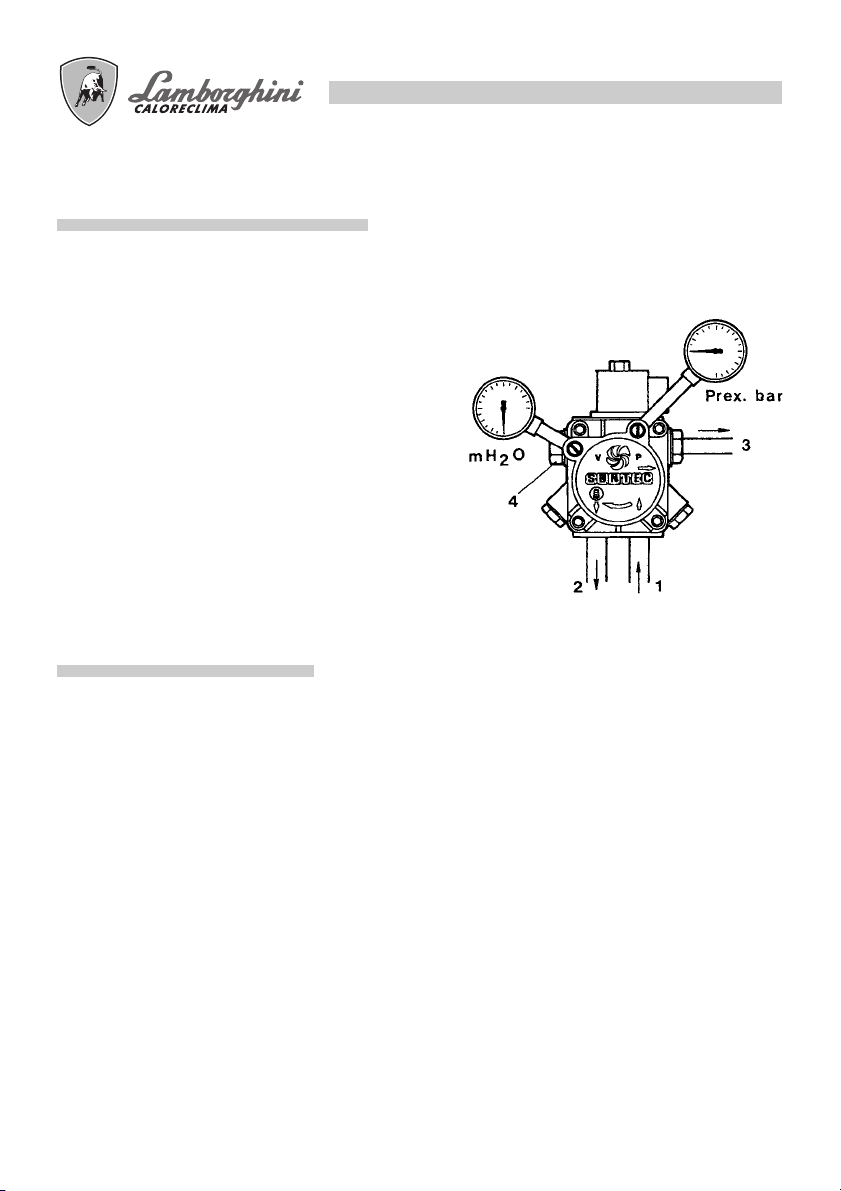
REGOLAZIONE PRESSIONE POMPA
La pompa è pretarata a 12 bar.
Per il controllo della pressione servirsi di un manometro a bagno d’olio.
La pressione può essere normalmente regolata fra 11 e 15 bar.
1 - Aspirazione
2 - Ritorno
3 - Ugello
4 - Regolazione pressione
N.B. Se il vuoto supera 4 m. prevedere una pompa di circolazione
CONTROLLO COMBUSTIONE
17
Al fine di ottenere i migliori rendimenti di combustione, e nel rispetto dell’ambiente, si raccomanda di effettuare con gli adeguati strumenti, controllo e regolazione della combustione. Valori fondamentali da considerare
sono:
-CO2 Indica con quale eccesso d’aria si svolge la combustione; se si aumenta l’aria, il valore di CO2 %
diminuisce, e se si diminuisce l’aria di combustione il CO2 % aumenta. Valori accettabili sono 11-12 %.
-Numero di fumo (Bacharach). Sta ad indicare che nei fumi sono presenti particelle di incombusto solido.
Se si supera il n°2 della scala BH occorre verificare che l’ugello non sia difettoso e che sia adatto al
bruciatore ed alla caldaia (marca, tipo, angolo di polverizzazione). In genere il n° BH tende a diminuire
alzando la pressione in pompa; é necessario, in questo caso fare attenzione alla portata del combustibile
che aumenta, e quindi, eventualmente, ridurre la capacità dell’ ugello.
-Temperatura dei fumi. È un valore che rappresenta la dispersione di calore attraverso il camino; più alta
é la temperatura, maggiori sono le dispersioni e più basso é il rendimento di combustione.
Con i bruciatori funzionanti ad alta/bassa fiamma, é necessario accertarsi che non si creino le condizioni per
la condensazione dei fumi, in caldaia ed al camino. La condensa, essendo di tipo acido, potrebbe provocare
gravi corrosioni alla caldaia, pertanto é necessario consultare il costruttore della medesima a riguardo. Per
quanto concerne il camino, a seconda del materiale con cui é costruito, si possono creare fenomeni di corrosione, macchie scure di umidità e difficoltà nello smaltimento dei fumi (insufficiente tiraggio).
N.B.: Disposizioni vigenti in alcuni paesi possono richiedere regolazioni diverse da quelle riportate e
richiedere anche il rispetto di altri parametri. I bruciatori sono progettati per rispettare le più rigide
normative internazionali per il risparmio dell’energia e la tutela dell’ambiente
18
MANUTENZIONE
Tutte le operazioni devono essere eseguite dopo aver tolto corrente. Togliendo il cofano é possibile effettuare
la pulizia della fotoresistenza, ispezionare il motore, la valvola elettromagnetica, il trasformatore ed il
servocomando serranda aria.
Per effettuare la pulizia/ispezione ugello - elettrodi, normalmente si estrae il gruppo testata attraverso la
rimozione della piastra superiore.
FOTO RESISTENZA
Sfilarla dalla sua sede e pulire la sua parte sensibile con un panno asciutto.
FILTRO POMPA
Chiudere la saracinesca sull’aspirazione, smontare il coperchio della pompa, estrarre la cartuccia a rete,
lavarla con benzina, e risciacquarla con gasolio. Rimontare il tutto con molta cura.
FILTRO DI LINEA
Chiudere la saracinesca sull’aspirazione, smontare il cestello filtro, normalmente avvitato sul corpo filtro, e
procedere ad una accurata pulizia della rete filtrante. Rimontare il tutto con molta cura.
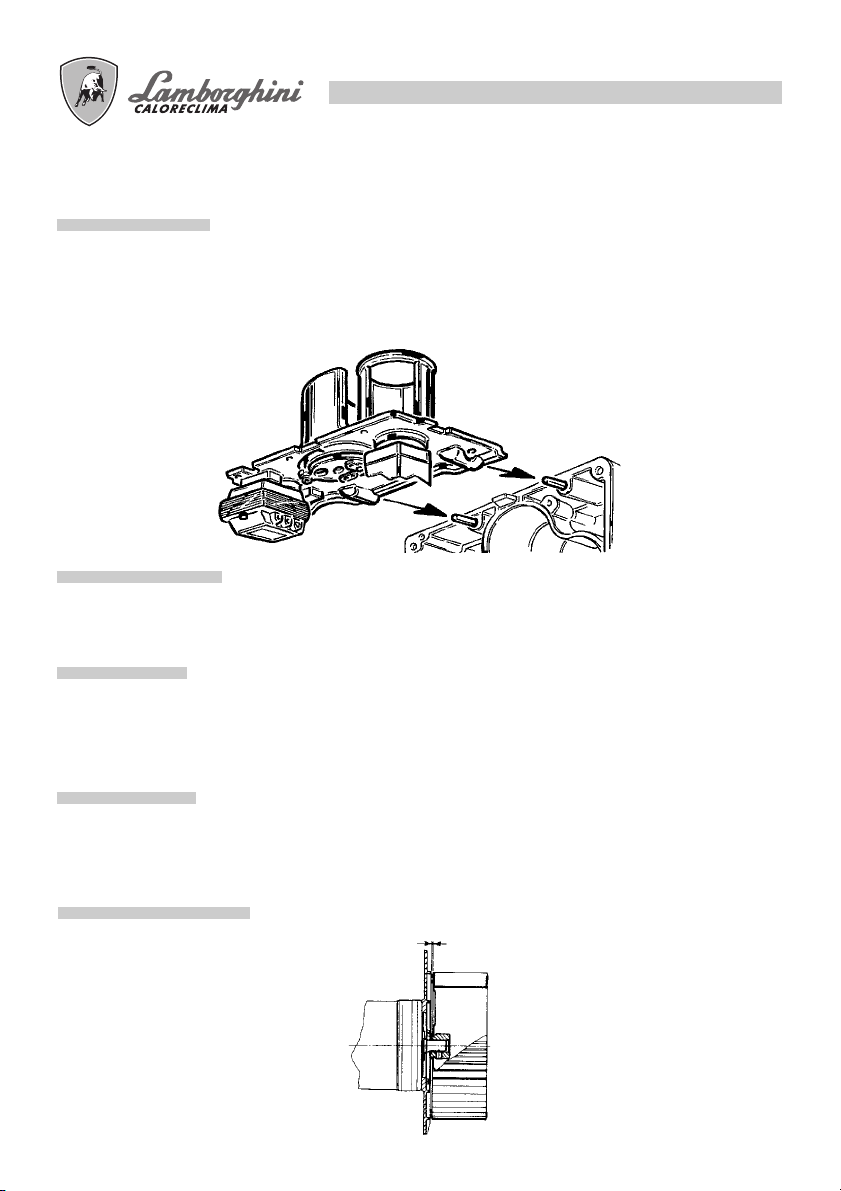
POSIZIONE VENTOLA
0÷0.5
19
ELETTRODI - UGELLO
Dopo aver tolto il cofano, sfilare i cavi di alta tensione dal lato trasformatore, sfilare la fotoresistenza, svitare
i raccordi che collegano i tubi del gasolio alle linee degli ugelli, allentare le viti della piastra superiore ed
estrarla con il gruppo flangia-ugello-deflettore-elettrodi.
Svitare le viti 5, per togliere il deflettore e la vite 6 per togliere gli elettrodi. Una buona pulizia dell’ugello si
ottiene smontando il filtro e pulendo i tagli ed il foro di polverizzazione, con benzina e risciacquarlo con
gasolio. Nel rimontare il tutto si faccia attenzione al corretto posizionamento degli elettrodi-deflettore.
6
5

IRREGOLARITA' DI FUNZIONAMENTO
20
DIFETTO
IL BRUCIATORE NON PARTE E NON C’È
SEGNALE DI BLOCCO.
IL MOTORE GIRA
MA NON SI HA
FORMAZIONE DELLA
FIAMMA, CON
ARRESTO IN
BLOCCO.
IL BRUCIATORE
SI AVVIA, SI HA
FORMAZIONE DELLA
FIAMMA E POI SI
ARRESTA IN BLOCCO.
LA FIAMMA È IRREGOLARE, È CORTA CON
SCINTILLE.
LA FIAMMA È
FUMOSA
a) Mancanza di energia elettrica.
b) Non arriva il combustibile
al bruciatore.
a) Non avviene la scarica
agli elettrodi.
b) Ugello otturato.
c) Non arriva il combustibile.
a) Fotoresistenza sporca.
b) Ugello che polverizza male.
a) Ugello polverizza male.
b) La pressione in pompa
è troppo bassa.
c) C’è acqua nel gasolio.
a) Ugello polverizza male.
b) Poca aria di combustione.
RIMEDIOCAUSA
a) Controllare i fusibili.
b) Controllare i termostati (ambiente,
caldaia e sicurezza).
c) Controllare la
linea di alimentazione.
a) Verificare la corretta posizione
delle punte e pulirle.
b) Pulire o sostituire l’ugello.
c) Verificare: il livello di gasolio in
cisterna; che le saracinesche lungo
la linea gasolio siano aperte;
la pulizia del filtro di linea e della
pompa.
a) Pulire la fotoresistenza.
b) Pulire o sostituire l’ugello.
a) Pulire o sostituire l’ugello.
b) Controllare e alzare la pressione
c) Fare togliere l’acqua dalla
cisterna e pulire i filtri.
a) Pulire o sostituire l’ugello.
b) Verificare che la serranda
atmosferica apra regolarmente;
verificare che la ventola non sia
sporca

GB
Please read the instructions and warnings in this document carefully as there is important
information regarding installation, use and maintenance. Keep the manual in a safe place
for future reference. The installation must be carried out by qualified personnel that will be
responsible for conformance with current safety regulations in force.

22
CONTENTS PAGE
GENERAL INFORMATION _______________________________________________________ 23
DESCRIPTION _________________________________________________________________ 25
DIMENSIONS mm ______________________________________________________________25
TECHNICAL SPECIFICATIONS ____________________________________________________ 26
PRESSURE CURVE ______________________________________________________________26
ASSEMBLY WITH THE FURNACE__________________________________________________27
FLAME DIMENSION ____________________________________________________________ 27
ELECTRICAL CONNECTIONS ____________________________________________________ 28
LIGHT OIL SUPPLY ______________________________________________________________29
SINGLE LINE FUEL SUPPLY _______________________________________________________29
DOUBLE LINE FUEL SUPPLY ______________________________________________________29
CHOKE SELECTION ____________________________________________________________ 30
EXAMPLE OF CHOKE SELECTION ________________________________________________ 30
MOUNTING THE CHOKE _______________________________________________________30
ELECTRODE-DEFLECTOR POSITIONING ___________________________________________ 31
OPERATION CYCLE ____________________________________________________________ 31
DIAGNOSIS OF CAUSE OF FAULT LMO44 _________________________________________32
COMBUSTION HEAD ADJUSTMENT ______________________________________________ 33
AIR INTAKE ADJUSTMENT_______________________________________________________ 33
STARTING PROCEDURES ________________________________________________________ 34
PUMP PRESSURE ADJUSTMENT __________________________________________________ 35
COMBUSTION CONTROL _______________________________________________________ 35
MAINTENANCE _______________________________________________________________ 36
PHOTO RESISTANCE ___________________________________________________________36
PUMP FILTER___________________________________________________________________36
FUEL LINE FILTER _______________________________________________________________ 36
FAN POSITION ________________________________________________________________ 36
ELECTRODES – CHOKE _________________________________________________________37
TROUBLE SHOOTING___________________________________________________________ 38
Congratulations...
...For an excellent choice. We thank you for choosing our products. Since 1959, LAMBORGHINI
CALORECLIMA has been actively present in Italy and the world with an extensive network of agents and
dealers, which guarantees the constant presence of our products on the market.
This network is supported by the technical assistance service «LAMBORGHINI SERVICE» with the responsibility of qualified maintenance of the product.
For installation and for positioning the furnace,
SCRUPULOUSLY RESPECT THE LOCAL REGULATIONS IN FORCE

23
GENERAL INFORMATION
● This manual is an essential and integral part of the product and should be given to the installer.
Please read the instructions and warnings in this document carefully as there is important information
regarding installation, use and maintenance.
Keep the manual in a safe place for future reference. The installation of the burner must be carried out in
compliance with the current regulations in force, following the instructions of the manufacturer and by
qualified personnel only. An incorrect installation may cause damages to persons, animals and property,
for which the manufacturer is not responsible.
● This machine must be operated only for its clearly intended and expressed use. Any other use shall be
considered improper and dangerous. The manufacturer cannot be held responsible for any eventual
damages cause by improper, incorrect or unreasonable use.
● Before carrying out any operations of cleaning or maintenance, disconnect the burner from the electrical
and fuel supplies by using the general switch on the burner or via the appropriate circuit breaker.
● In case of breakage or malfunction, switch the machine off and do not attempt any form of repair or
direct intervention.
Contact only professionally qualified personnel.
Any repair of the product should only be carried out by a company-authorised repair centre, using
exclusively, original parts.
Any deviation from the above mentioned indications can compromise the safety of the burner.
To guarantee the correct and efficient functioning of the burner, it is important to follow the manufacturer’s indications by having all periodic maintenance carried out by professionally qualified personnel.
● In the case of non-utilisation of the burner, be sure to render harmless any pieces that might represent a
potential danger.
● Before starting the burner, qualified personnel should verify:
a) that the information on the data plate is as required for the electrical and light oil feed;
b) that the settings of the burner are compatible with the output of the furnace;
c) that the flow of air and light oil, and the exhaust of smoke operate correctly with regards to the
regulations in force;
d) insure that normal ventilation and maintenance of the burner are guaranteed.
● Before carrying out any operation regarding the dismantling of the burner or opening inspection panels
or windows, disconnect the electrical supply and close the light oil feed.
● Do not store containers of flammable substances near the location of the burner.
● The location of the burner should have ventilation towards the outside, to supply air for the burner, as in
compliance with local regulations in force. In case of doubt concerning the circulation of air, it is
recommended to measure the CO2 level with the burner functioning at maximum output, with the location
ventilated, but only through the normal ventilation openings as mentioned above. Then measure the CO
level a second time with the door of the burner location opened. In both cases, the CO2 level should not
change in a significantly. If the CO2 level does change, the outside ventilation should be increased. In the
case of finding more than one burner and one ventilation opening in the same location, this test should be
carried out with all the devices operating at the same time.
2

24
● Never block the openings for air in the location of the burner, the air intakes for the fan or any other
existing air conduit or ventilation or outlet grill. This is to avoid:
the formation of mixtures of toxic or explosive gasses in the air, in the location of the burner;
combustion with insufficient air, causing malfunctions which can be dangerous, costly or polluting.
● The burner must be protected from rain, snow and freezing.
● The location of the burner must always be kept clean and free of volatile substances that could be sucked
into the fan and block internal conductors of the burner or the combustion head. Dust is extremely
damaging, particularly so if it accumulates the fan blades. This can cause a reduction in ventilation and
provoke pollution during combustion. Dust can also accumulate on the rear of the flame deflector disk in
the combustion head, causing an inadequate mixture of air and fuel.
● The burner must be supplied with the type of fuel as indicated on the data plate and in the technical
specifications supplied in this manual. The fuel line to the burner must be perfectly sealed and rigid.
Furthermore, it must have all the mechanisms for control and safety as specified in the local regulations
in force. Give particular attention and care that no extraneous material gets into the line during installation.
● Never exchange the neutral electrical cables with the phase cables.
● The burner may be attached to the electrical system with a plug and socket, only if this configuration does
not cause the inversion of the phase with the neutral. Install a general switch in the control panel of the
furnace in compliance with local regulations in force.
● The entire electrical system and in particular, all cable gauges must be adequate for the value of the
maximum current absorbed, as indicated on the data plate of the burner and in this manual.
● If the electrical cable of the burner is defective, it should only be changed by qualified personnel.
● Never touch the burner with any wet part of the body or without wearing shoes.
● Do not pull or force the electrical cables and keep them away from any source of heat.
● The length of the cables utilised must be sufficient to allow the opening of the burner and possibly, its
removal from the furnace.
● The electrical connections must be carried out exclusively by qualified personnel and must respect com-
pletely, the local regulations in force concerning electrical material.
● After having removed all packaging materials, check the contents to insure that nothing has been dam-
aged in any way during transport.
In case of doubt, do not use the burner and contact the supplier.
The packaging materials (wooden cage, boxes, plastic bags, polystyrene foam, staples, etc.) represent a
type of pollution and potential risk if left lying around. Therefore, the materials should be collected and
disposed of in an adequate manner (and in an adequate place).
25
DESCRIPTION
These are mechanically atomised, light oil burners. The path of the air flow has been studied to obtain a high
pressure curve with a uniform and linear air flow from the fan. The dosage of air in the combustion is obtained
with a double control: one on the choke line with movement of the deflector disk on a conical trunk head, and
the other with a shutter on the fan air intake. This system permits us to obtain optimum conditions of pressure/
air flow in the entire working area of the burner, in order to obtain combustion with a low excess of air, high
effective output and a high energy level with a low level of pollutants, CO and Nox. The air shutter is closed
completely when the burner is turned off, to limit the dispersion of heat from the burner during rest periods. It
is motorised with a electric air flow control with three positions: closed-open first flame, open second flame.
All of the components are protected by an elegant case, which also serves as a good silencer. The function is
automatic with surveillance of the flame by means of a photo resistance sensor. There is an auto-suction pump
with one or two tubes, an incorporated bypass and electromagnetic valve. The burners may be inspected
completely, which makes for rapid and easy control and maintenance.
Types ECO 50/2 and ECO 70/2 with double choke, with reduced output start-up and high/low flame function.
DIMENSIONS mm.
Model
ECO 50/2
ECO 70/2
Ø
ABCDEFØ GH LNXø
1040 420 490 655 385 392 140 121÷160 150 200 3/8” M10
1080 420 490 695 385 392 170 160÷200 180 230 3/8” M14
POTENZA kW
ECO 50/2
PRESSIONE FOCOLARE (mbar)
TECHNICAL SPECIFICATIONS
MODEL ECO 50/2 ECO 70/2
Output Min. kW 177 197
Max. kW 585 776
Min. kcal/h 152.300 169.000
Max. kcal/h 503.200 667.600
Fuel consumption Min. Kg/h (15) - 21,4 (16,6) - 27
Max. Kg/h 49,3 65,4
Pressure calibration of the fuel pump bar 12 12
Fuel light oil p.c.i. 10200 (6cst) a 20°C
Weigh kg 55 59
Motor W 1.100 1.500
Condenser 450 V A 2,7-4,4 2,7-4,4
Ignition transformer kV/mA 12/35 12/35
Electrical supply 230/400V - 50 Hz three-phase
Electrical energy consumption W 1.500 1.900
Flame control Electronic/photo resistance Electronic/photo resistance
Air flow control Motorised Motorised
Number of stages 2 2
NOTE: The specifications in parenthesis refer to the minimum delivery you obtain with the 1st flame
kcal/kg1,50°E
26
PRESSURE CURVE
9
8
7
6
5
4
3
2
Combustion chamber pressure (mbar)
1
0
100 200 300 400 500 600 700 800
POWER kW
Indicates power in kW, in function of back pressure, in mbar, in the combustion chamber.
ECO 70/2

27
ASSEMBLY WITH THE FURNACE
1 4
3 2 5
Attach the flange 2 to the furnace with n° 4 screws (3) through the sealing gasket (4) and any seals (5). Insert
the burner in the flange so that the nozzle enters the combustion chamber as indicated by the manufacturer of
the furnace. Tighten the screw (1) to lock the burner in place.
FLAME DIMENSION
The dimensions are indicative, being influenced by:
● excess of air
● form of the combustion chamber
● path of smoke exhaust from the furnace (direct/reverse)
● pressure in the combustion chamber
Mcal/h
200
400
600
800
Flame diameter
Diametro fiamma Lunghezza fiamma
0
D = 50
D = 60
10 20 30 40 50 60 70 80 90
fiamma
Flame
Test tube
tubo prova
100
218 M cal
115 cm
Flame length
667 M cal
200 cm
180 200 220 240120 140 160100806040
cm
28
ELECTRICAL CONNECTIONS
The connections to be made by the installer are as follows:
● Electrical supply line
● Thermostat line
● War ning light (optional)
● Timer (optional)
● Flame control thermostat (optional)
Eliminate any cable bridges
N.B. It is necessary to observe scrupulously normal working practices that indicate attachment of no more
than two cables per terminal.
War ning:
● Do not exchange the neutral with the phase
● Be sure to make a good connection for the ground wire
● Respect normal working practices and observe scrupulously local regulations in force
LEGEND
BRM Motor Relay Spool
CRT Thermal Relay Contact
F Fuse
FA Matched Filter
FR Photo Resistance
IG Main Switch
Ima On/Off Switch
ImM Min./Max Switch
MB Burner Motor
MMS Air Intake Control, Motor Reducer Clamp
MPE Morset. Apparec. Landis LOA-LMO 44
RM Motor Relay
RT Thermal Relay
TMF 2° Flame Modulation Thermostat (optional)
TP Timer
TR Transformer
TS Back-up Thermostat
VE1 1° Flame Electromagnetic Valve
VE2 2° Flame Electromagnetic Valve
29
LIGHT OIL SUPPLY
The dimensions of the fuel lines (diameter/length) are related to the type of burner (with one or two lines, in
suction feed / gravity feed) and with the pump specifications.
The diagram indicates the maximum length L allowed in a suction feed line with regards to the difference in
height of the fuel tank and the internal diameter of the tube d, for an atmospheric pressure of 1013 mbar and
a vacuum of 0.45 bar, considering assembly with 4 elbows of a stop valve and a one-way valve.
SINGLE LINE FUEL SUPPLY
It is recommended whenever possible to avoid this option, which can create significant malfunctions in the
burner if the installation has not been performed in a perfect manner. However, if it is not possible to avoid this
choice, we advise: use a gravity feed burner only, modify the pump by removing the Allen-head screw inside,
discharge air from the upper parts of the fuel line and avoid air bubbles.
DOUBLE LINE FUEL SUPPLY
Hí
3
2
1
0
10 20 30 605040 908070 100
1
2
3
3,5
IN ASPIRAZIONE A CADUTA
H
Ø8
Ø10
L
Ø12
30
CHOKE SELECTION
The selection is made in relation to the effective output of the furnace, considering that light oil has a calorific
power (P.C.I.) of 10,200 kcal/kg. The table indicates the theoretic output or consumption, in kg/h and in kW,
of light oil in relation to the size of the choke (GPH) and of the pump pressure (in bar). In double-choke
burners, the output is subdivided, approximately, by 40% for the first flame choke and 60% for the second
choke.
CHOKE
GPH
2,00
2,50
3,00
3,50
4,00
4,50
5,00
6,00
7,00
8,30
9,50
10,50
10 11 12 13 14 15 16 17 18 19 20 21
7,43 7,75 8,10 8,42 8,80 9,05 9,35 9,67 9,91 10,22 10,48 10,70
88,12 91,91 96,06 99,86 104,37 107,33 110,90 114,68 117,53 121,21 124,30 126,90
9,28 9,67 10,17 10,54 10,98 11,27 11,70 12,10 12,38 12,76 13,10 13,40
110,06 114,68 120,62 125,00 130,22 133,66 138,76 143,50 146,82 151,33 155,36 158,92
11,17 11,60 12,16 12,65 13,20 13,60 14,10 14,50 14,88 15,16 15,70 16,10
132,47 137,58 144,22 150,03 156,55 161,30 167,22 171,98 176,47 179,80 186,20 190,94
13,05 13,60 14,20 14,78 15,40 15,85 16,40 16,95 17,38 17,90 18,30 18,80
154,77 161,30 168,41 175,29 182,64 187,98 194,50 201,03 206,12 212,29 217,04 222,97
14,88 15,50 16,24 16,90 17,60 18,12 18,70 19,37 19,88 20,40 21,00 21,50
176,47 183,83 192,60 200,43 208,73 214,90 221,78 229,73 235,77 241,94 249,06 255,00
16,67 17,35 18,20 18,90 19,70 20,30 21,00 21,70 22,25 22,90 23,50 24,00
197,70 205,77 215,85 224,15 233,64 240,76 249,06 257,36 263,88 271,60 278,71 284,64
18,60 19,35 20,30 21,10 22,00 22,60 23,35 24,15 24,80 25,50 26,20 26,70
220,60 229,49 240,76 250,24 260,92 268,03 286,42 294,13 307,36 310,73 316,66
22,30 23,25 24,35 25,30 26,40 27,20
264,48 275,74 288,80 300,06 313,10 322,59
26,00 27,15 28,40 29,50 30,70 31,70
308,36 322,00 336,82 349,87 364,10 375,96
30,80 32,10 33,60 34,90 36,40 37,50
365,29 380,70 398,50 413,91 431,70 444,75
35,30 36,70 38,50 40
418,66 435,26 456,61 474,4
39,00 40,65
462,54 482,11
PUMP PRESSURE bar (kg/cm2)
276,93
28,10
29,00 29,75 30,75 31,40 32,20
343,94 352,83 364,49 372,40 381,90
333,26
33,90 34,80 35,80 36,65 37,50
32,70
402,05 412,73 424,59 434,67 444,75
387,82
38,75
40,20
476,77
45957
EXAMPLE OF CHOKE SELECTION
The furnace has an effective output of 290 kW.
For a pump pressure of 12 bar, the nearest value is 288.80 kW, which corresponds to a choke of 6 GPH. If it
is a double-choke burner, divide the feed with a choke of 2.50 GPH on the first flame and 3.50 GPH on the
second flame.
If is does not have an optimum choke, it is possible, within the limits of 11 –14 bar, to adjust the pump pressure
to obtain the desired fuel supply.
MOUNTING THE CHOKE
Once having chosen the correct choke, it may be mounted as indicated in the paragraph “MAINTENANCE”.
 Loading...