

Page 1
AZIENDA CERTIFICATA UNI EN ISO 9001
UNI EN ISO 9001 CERTIFIED COMPANY
IT
FR
ES
UK
DE
GR
BRUCIATORE DI GASOLIO
LIGHT OIL BURNERS
ECO 15 - 20 -15/2 - 20/2
MANUALE DI INSTALLAZIONE E MANUTENZIONE
INSTALLATION AND MAINTENANCE MANUAL
Page 2

ITALIANO
IT
Leggere attentamente le istruzioni ed avvertenze contenute sul presente libretto in quanto forniscono
importanti indicazioni riguardanti la sicurezza d’installazione, d’uso e di manutenzione. Conservare
con cura questo libretto per ogni ulteriore consultazione. L’installazione deve essere effetuata da per-
sonale qualicato che sarà responsabile del rispetto delle norme di sicurezza vigenti.
UK
FR
DE
ES
ENGLISH
Read all warnings and instructions contained in this manual carefully as they give important safety
instructions regarding installation, use and maintenance.
Keep this manual for future reference. Installation must be carried out by qualied personnel who will
be responsible for observance of safety standard in force.
FRANÇAIS
Lire attentivement les instructions et les recommandations contenues dans la présente notice car elles
fournissent des informations importantes sur la sécurité de l’installation, de l’utilisation et de l’entretien. Bien conserver la présente notice pour toute consultation ultérieure. L’installation doit être prise
en charge par un personnel qualié responsable du respect des normes de sécurité en vigueur.
DEUTSCH
Lesen Sie die Anleitungen in diesem Handbuch aufmerksam durch, da sie Ihnen wichtige Hinweise für eine sichere Installation, Wartung und einen sicheren Betrieb liefern. Bewahren Sie dieses
Handbuch für spätere Verwendung sorgfältig auf. Die Installation muss von Fachpersonal ausgeführt
werden, das für die Einhaltung der geltenden Sicherheitsvorschriften verantwortlich ist.
ESPAÑOL
Lea detenidamente las instrucciones y advertencias que contiene el presente manual ya que aportan
indicaciones importantes concernientes a la seguridad de la instalación, de empleo y de manteni-
miento. Conserve con cuidado este manual para cualquier consulta que pueda necesitar en el futuro.
La instalación debe ser efectuada por personal cualicado que será responsable del respeto de las
normas de seguridad vigentes.
PT
RO
RU
GR
PORTUGUÊS
Leia atentamente as instruções e advertências contidas neste manual: este documento fornece im-
portantes indicações em relação à segurança para uma correta instalação, utilização e manutenção.
Armazene cuidadosamente este manual, para eventuais e futuras leituras. As operações de insta-
lação devem ser realizadas por pessoal altamente qualicado, responsável pelo cumprimento das
normas de segurança em vigor no local de instalação.
ROMÂNĂ
Citiţi cu mare atenţie acest manual care furnizează indicaţii importante referitoare la siguranţa, instalarea, folosirea şi întreţinerea produsului. Păstraţi manualul cu grijă pentru oricare consultare ulterioară.
Instalarea trebuie să e efectuată de personal calicat în conformitate cu normele tehnice, cu legislaţia
naţională şi locală în vigoare şi cu indicaţiile redate în manualul cu instrucţiuni furnizat odată cu apa-
ratul.
РОССИЯ
Внимательно прочитать данное руководство, содержащее важную информацию по
безопасности, установке и техническому обслуживанию изделия. Бережно хранить руководство
для последующих консультаций. Установка должна осуществляться квалифицированными
специалистами в соответствии со всеми техническими нормами, действующими национальным
и местным законодательствами и указаниями, приведенными в инструкции, прилагающейся к
устройству.
ΕΛΛΗΝΙΚΑ
Διαβάστε προσεκτικά τις οδηγίες και τις προειδοποιήσεις που περιέχονται στο παρόν εγχειρίδιο αφού
παρέχουν σημαντικές υποδείξεις σχετικές με την ασφάλεια εγκατάστασης, χρήσης και συντήρησης.
Φυλάξτε προσεκτικά το εγχειρίδιο, ώστε να μπορείτε να ανατρέξετε σε αυτό στο μέλλον. Ηεγκατάσταση
πρέπει να διενεργηθεί από ειδικευμένο προσωπικό που θα είναι υπεύθυνο για την τήρηση των
ισχυόντων κανόνων ασφαλείας.
Page 3

Complimenti….…per l’ottima scelta.
La ringraziamo per la preferenza accordata ai nostri prodotti.
LAMBORGHINI CALORECLIMA è una Azienda quotidianamente impegnata nella ri-
cerca di soluzioni tecniche innovative, capaci di soddisfare ogni esigenza. La presenza
costante dei nostri prodotti sul mercato italiano e internazionale è garantita da una rete
capillare di Agenti e Concessionari. Questi sono afancati dai Servizi di Assistenza,
“LAMBORGHINI SERVICE”, che assicurano una qualicata assistenza e manutenzione dell’apparecchio.
GARANZIA
I bruciatori ECO godono di una GARANZIA SPECIFICA a partire dalla data di convalida da parte del Servizio di Assistenza della Sua Zona. La invitiamo quindi a rivolgersi
tempestivamente al suddetto.
CONFORMITA’
I bruciatori ECO sono conformi a:
• Direttiva Compatibilità Elettromagnetica 2004/108/CE
• Direttiva Bassa Tensione 2006/95/CE
Per il numero di serie di produzione riferirsi alla targhetta tecnica del bruciatore.
INDICE
NORME GENERALI 4
DIMENSIONI 7
CARATTERISTICHE TECNICHE 8
CURVE DI LAVORO 8
MONTAGGIO ALLA CALDAIA 9
CICLO DI FUNZIONAMENTO 11
COLLEGAMENTI ELETTRICI 12
REGOLAZIONI 14
INSTALLAZIONE 16
APPARECCHIATURA 17
MANUTENZIONE 18
IRREGOLARITÀ DI FUNZIONAMENTO 20
Paragrafo di interesse
per l’utilizzatore
U
M
Paragrafo di interesse
per il tecnico
ITALIANO
IT
3
Page 4

4
IT
NORME GENERALI E AVVERTENZE
Il presente libretto costituisce parte integrante ed essenziale del prodotto e dovrà essere consegnato all’installatore. Leggere attentamente le avvertenze contenute nel
presente libretto in quanto forniscono importanti indicazioni riguardanti la sicurezza
d’installazione, d’uso e manutenzione.
Conservare con cura questo libretto per ogni ulteriore consultazione. L’installazione
del bruciatore deve essere effettuata in ottemperanza alle norme vigenti, secondo le
istruzioni del costruttore e da personale qualicato. Un’errata installazione può causare danni a persone, animali o cose, per i quali il costruttore non è responsabile.
Questo apparecchio dovrà essere destinato solo all’uso per il quale è stato espressamente previsto.
Ogni altro uso è da considerarsi improprio e quindi pericoloso.
Il costruttore non può essere considerato responsabile per eventuali danni causati da
usi impropri, erronei ed irragionevoli.
Prima di effettuare qualsiasi operazione di pulizia o di manutenzione, disinserire l’apparecchio dalla rete di alimentazione o agendo sull’interruttore dell’impianto o attraver-
so gli appositi organi di intercettazione.
UM
In caso di guasto e/o di cattivo funzionamento dell’apparecchio, disattivarlo, astenendosi da qualsiasi tentativo di riparazione o di intervento diretto.
Rivolgersi esclusivamente a personale professionalmente qualicato.
L’eventuale riparazione dei prodotti dovrà essere effettuata solamente da un centro
di assistenza autorizzato dalla casa costruttrice utilizzando esclusivamente ricambi
originali.
Il mancato rispetto di quanto sopra può compromettere la sicurezza dell’apparecchio.
Per garantire l’efcienza dell’apparecchio e per il suo corretto funzionamento è indi-
spensabile attenersi alle indicazioni del costruttore, facendo effettuare da personale
professionalmente qualicato, la manutenzione periodica dell’apparecchio.
Allorchè si decida di non utilizzare più l’apparecchio, si dovranno rendere innocue
quelle parti che possono diventare potenziali fonti di pericolo.
Prima di avviare il bruciatore per la prima volta far vericare da personale qualicato:
a) che i dati di targa siano quelli richiesti dalla rete di alimentazione gas elettrica;
b) che la taratura del bruciatore sia compatibile con la potenza della caldaia;
c) che l’afusso di aria comburente e l’evacuazione dei fumi avvengano correttamente
secondo le norme vigenti;
d) che siano garantite l’aerazione e la normale manutenzione del bruciatore.
Page 5

5
IT
Prima di effettuare qualsiasi intervento che preveda lo smontaggio del bruciatore o
l’apertura di accessi di ispezione, disinserire la corrente elettrica.
Non depositare contenitori con sostanze inammabili nel locale ove è situato il bruciatore.
Il locale del bruciatore deve possedere delle aperture verso l’esterno conformi alle
norme locali in vigore. In caso di dubbio relativamente alla circolazione dell’aria, ci rac-
comandiamo di misurare anzitutto il valore del CO2, con il bruciatore funzionante alla
sua massima portata ed il locale ventilato, solamente tramite le aperture destinate ad
alimentare d’aria il bruciatore; poi, misurando il valore di CO2, una seconda volta, con
la porta aperta.
Il valore del CO2 misurato in entrambi i casi non deve cambiare in maniera signicativa.
In caso si trovassero più di un bruciatore e di un ventilatore nello stesso locale, questo
test deve essere effettuato con tutti gli apparecchi funzionanti contemporaneamente.
Non ostruire mai le aperture dell’aria del locale del bruciatore, le aperture di aspirazione del ventilatore del bruciatore ed un qualsiasi condotto dell’aria o griglie di ventilazione e di dissipazione esterni, allo scopo di evitare:
- la formazione di miscele di gas tossiche/esplosive nell’aria del locale del bruciatore;
- la combustione con aria insufciente, dalla quale ne deriva un funzionamento perico-
loso, costoso ed inquinante.
Il bruciatore deve essere sempre protetto dalla pioggia, dalla neve e dal gelo.
Il locale del bruciatore deve essere sempre mantenuto pulito e libero da sostanze
volatili, che potrebbero venire aspirate all’interno del ventilatore ed otturare i condotti
interni del bruciatore e della testa di combustione. La polvere è estremamente danno-
sa, particolarmente se vi è la possibilità che questa si posi sulle pale del ventilatore,
dove andrà a ridurre la ventilazione e produrrà inquinamento durante la combustione.
La polvere può anche accumularsi sulla parte posteriore del disco di stabilità amma
nella testa di combustione e causare una miscela povera aria/combustibile.
Il bruciatore deve essere alimentato con un tipo di combustibile per il quale è stato
predisposto come indicato sulla targhetta con i dati caratteristici e nelle caratteristiche
tecniche fornite in questo manuale. Inoltre dovrà essere dotato di tutti i meccanismi di
controllo e sicurezza richiesti dai regolamenti locali vigenti. Prestare particolare attenzione al fatto che nessuna materia esterna entri nella linea durante l’installazione.
Assicuratevi che l’alimentazione elettrica utilizzata per il collegamento sia conforme
alle caratteristiche indicate nella targhetta dei dati caratteristici ed in questo manuale.
Eseguire un impianto elettrico con un collegamento ad un efcace impianto di terra,
in conformità alle norme vigenti. Il cavo di terra deve essere lungo un paio di cm. in
più del conduttore di fase e del neutro. In caso di dubbio riguardo all’efcienza, deve
essere vericato e controllato da personale qualicato.
Page 6

6
IT
Non scambiare mai i cavi del neutro con i cavi della fase.
Il bruciatore può essere allacciato alla rete elettrica con un collegamento spina-presa,
solamente se questo risulti dotato in modo tale per cui la congurazione dell’accop-
piamento prevenga l’inversione della fase e del neutro. Installare un interruttore om-
nipolare con apertura tra i contatti di almeno 3 mm. a monte dell’apparecchio come
richiesto dalla legislazione esistente.
L’intero sistema elettrico e in particolare tutte le sezioni dei cavi, devono essere ade-
guati al valore massimo di potenza assorbita indicato sulla targhetta dei dati caratteristici dell’apparecchio e su questo manuale.
Se il cavo di alimentazione del bruciatore risulta difettoso, deve essere sostituito sola-
mente da personale qualicato.
Non toccare mai il bruciatore con parti del corpo bagnate oppure senza indossare
scarpe.
Non stirare (forzare) mai i cavi di alimentazione e mantenerli distanti da fonti di calore.
La lunghezza dei cavi utilizzati deve consentire l’apertura del bruciatore ed eventualmente della porta della caldaia.
I collegamenti elettrici devono essere effettuati esclusivamente da personale qualicato e devono essere scrupolosamente rispettate le regolamentazioni vigenti in materia
di elettricità.
Dopo aver tolto tutti i materiali dall’imballo, controllare i contenuti ed assicurarsi che
questi non siano stati in alcun modo danneggiati durante il trasporto. In caso di dubbio,
non utilizzate il bruciatore e contattate il fornitore.
I materiali di imballo (gabbie di legno, cartone, borse di plastica, espanso, graffe, ecc...)
rappresentano una forma di inquinamento e di potenziale rischio, se lasciati giacenti
ovunque; quindi occorre raggrupparli assieme e disporli in maniera adeguata (in un
luogo idoneo).
L’intero sistema elettrico e in particolare tutte le sezioni dei cavi, devono essere ade-
guati al valore massimo di potenza assorbita indicato sulla targhetta dei dati caratteristici dell’apparecchio e su questo manuale.
Se il cavo di alimentazione del bruciatore risulta difettoso, deve essere sostituito sola-
mente da personale qualicato.
Non toccare mai il bruciatore con parti del corpo bagnate oppure senza indossare
scarpe.
Page 7
7
IT
Non stirare (forzare) mai i cavi di alimentazione e mantenerli distanti da fonti di calore.
La lunghezza dei cavi utilizzati deve consentire l’apertura del bruciatore ed eventualmente della porta della caldaia.
I collegamenti elettrici devono essere effettuati esclusivamente da personale qualicato e devono essere scrupolosamente rispettate le regolamentazioni vigenti in materia
di elettricità.
Dopo aver tolto tutti i materiali dall’imballo, controllare i contenuti ed assicurarsi che
questi non siano stati in alcun modo danneggiati durante il trasporto.
In caso di dubbio, non utilizzate il bruciatore e contattate il fornitore.
I materiali di imballo (gabbie di legno, cartone, borse di plastica, espanso, graffe, ecc...)
rappresentano una forma di inquinamento e di potenziale rischio, se lasciati giacenti
ovunque; quindi occorre raggrupparli assieme e disporli in maniera adeguata (in un
luogo idoneo).
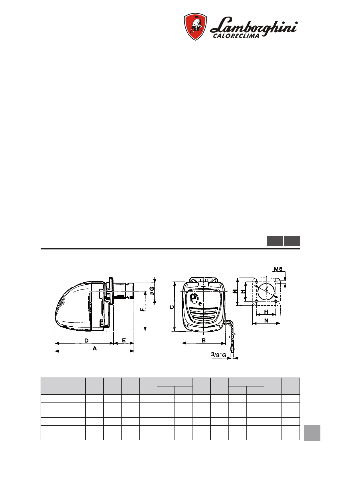
DIMENSIONI
Modello A B C D
ECO 15 550 275 340 400 80 150 274 114 110 150 120 180
ECO 15/L
ECO 15/2
ECO 20 535 275 340 400 60 135 274 114 110 150 120 180
ECO 20/L
ECO 20/2
685 275 340 400 80 285 274 114 110 150 120 180
700 275 340 400 60 300 274 114 110 150 120 180
E
m i n m a x m i n m a x
F Ø G
Ø H
M U
L N
Page 8
8
IT
CARATTERISTICHE TECNICHE
ECO 15
ECO 15/2
ECO 20
ECO 20/2
M U
DESCRiZiOnE
min 83 128 83 119 kW
Potenza termica
Consumo combustibile 7 - 14,8 11 - 21 7 - 14,8 10 - 20 kg/h
Combustibile gasolio p.c.i. 10.210 kcal/kg 1.5°E (6cSt) a 20°C
Tubazioni essibili 1/4” lunghezza 1100 mm (raccordo 3/8”)
Taratura pompa 12
Alimentazione elettrica 230/50-60 V/Hz
Condensatore 6,3 μF
Trasformatore di accensione 26 / 48 kV/mA
Peso 15 kg
Dimensioni imballo 640x335x400 760x360x440 mm
Ugelli * 1,75 - 3,50 2,50 - 5,00 1,75 - 3,00 2,225 - 4,00
max 176 249 176 237 kW
min 72.000 112.000 72.000 102.000 kcal/h
max 151.000 214.000 151.000 204.000 kcal/h
ECO 15
ECO 15/L
ECO 20
ECO 20/L
ECO 15/2 ECO 20/2
1° stadio 10
2° stadio 18
bar
* Tutti i tipi purchè a 60° CONO PIENO
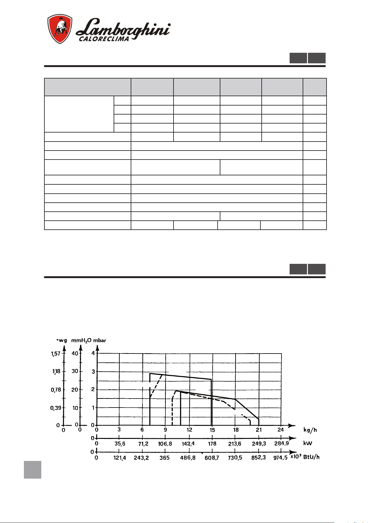
CURVE DI LAVORO
M U
Le curve rappresentate in diagramma sono state ottenute effettuando le prove di com-
bustione secondo le speciche e le caratteristiche di focolare previste dalle norme
vigenti.
Page 9
9
IT
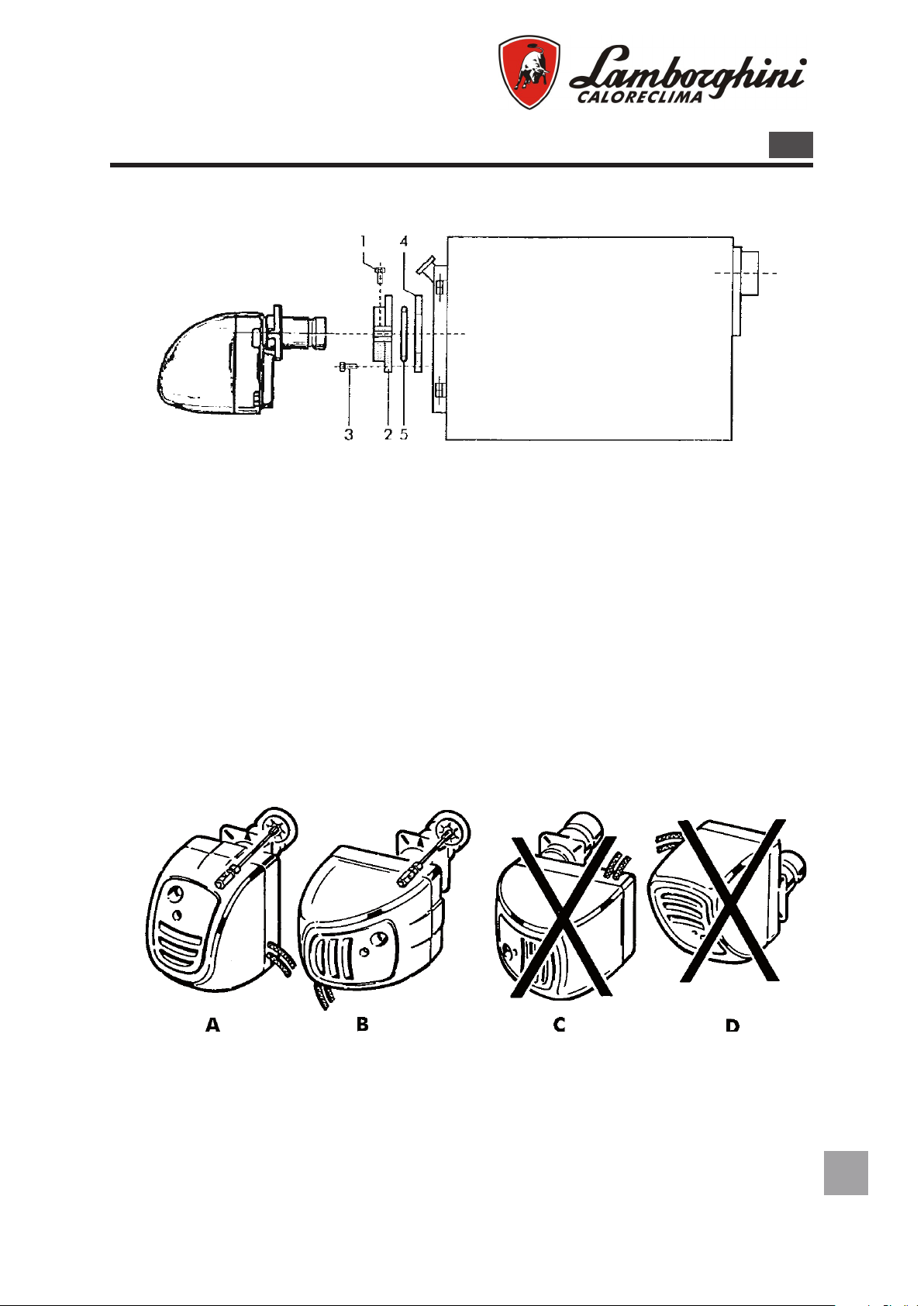
MONTAGGIO ALLA CALDAIA
Fissare la angia 2 alla caldaia con n° 4 viti 3 interponendo la guarnizione isolante 4 e
l’eventuale corda isolante 5. Inlare il bruciatore nella angia in modo che il boccaglio
penetri nella camera di combustione secondo le indicazioni del costruttore della calda-
ia. Stringere la vite 1 per bloccare il bruciatore.
M
POSIZIONAMENTO DEL BRUCIATORE
Consigliamo di montare il bruciatore sul generatore di calore nelle posizioni indicate
nelle gure A e B. Evitare il montaggio nelle posizioni C e D per non rendere inutilizzabile il dispositivo antigocciolamento creato nella canna portaugello e soprattutto
per consentire una buona regolazione della serranda presa aria e permettere la sua
immediata chiusura a bruciatore fermo.
IMPORTANTE: nel caso di installazione del bruciatore in posizione B occorre ruotare
di 60° il canotto portaugello in modo tale che la tacca esistente sul canotto sia rivolta
verso l’alto. Bloccare quindi il bruciatore tramite la vite e ssare poi la piastra di attac-
co con le due viti superiori.
Page 10
10
IT
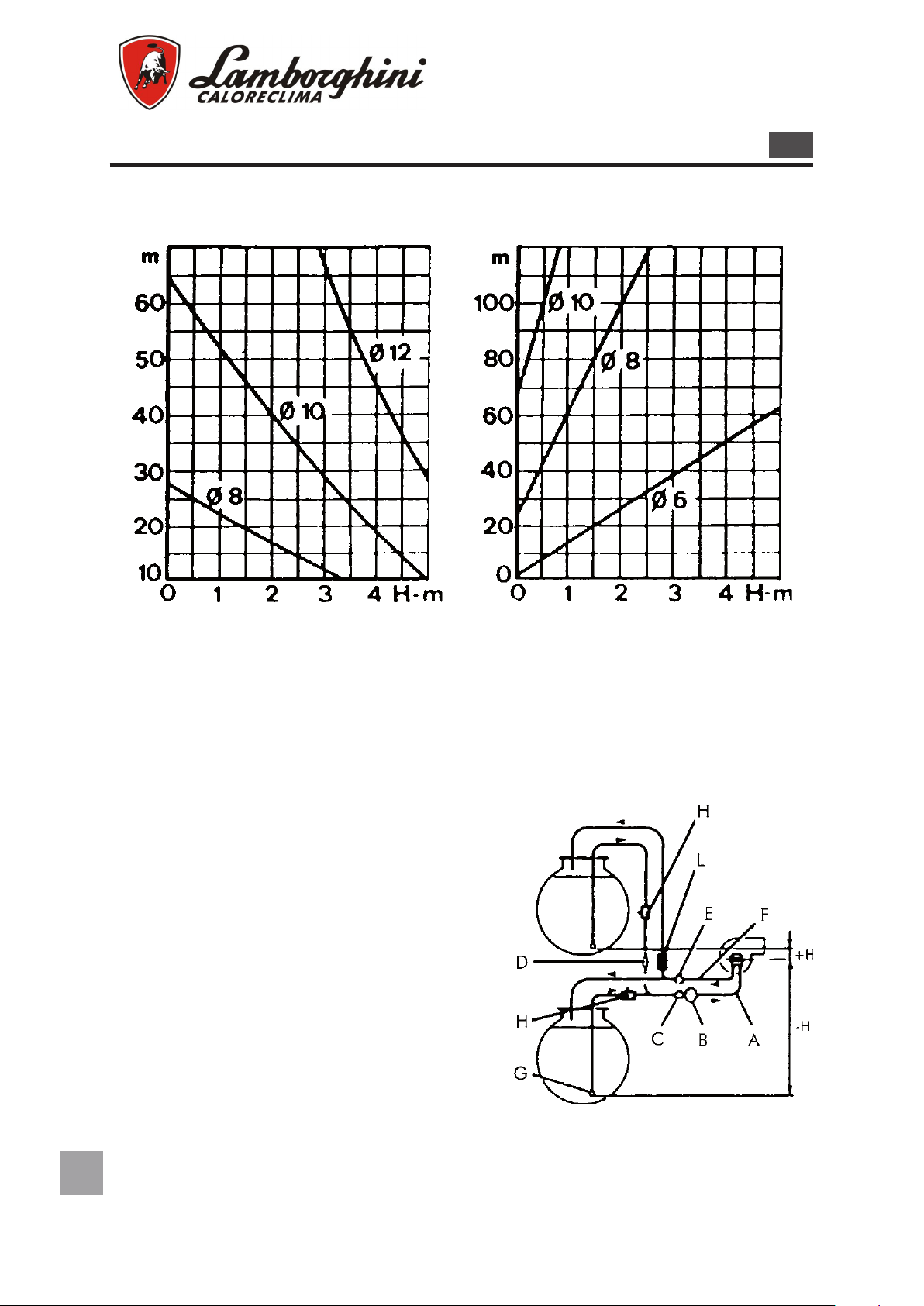
TUBAZIONI DI ALIMENTAZIONE OLIO COMBUSTIBILE
M
IMPIANTO IN ASPIRAZIONE
SVILUPPO TUBAZIONE
I diagrammi sono validi per olio combustibile avente viscosità max di 1,5°E (cSt) a 20°C.
IMPIANTO A CADUTA
Legenda
A Tubo di aspirazione
B Filtro combustibile
C Saracinesca su tubazione di aspirazione
D Elettrovalvola di arresto usso
E Saracinesca su tubazione di ritorno
F Tubazione di ritorno
G Valvola di fondo
H Saracinesca di intercettazione a chiusura
rapida con comando a distanza
L Valvola di ritegno unidirezionale
Page 11
11
IT
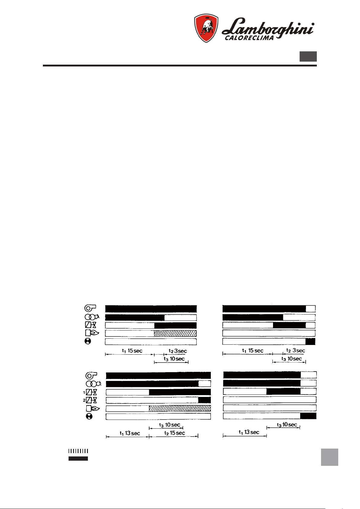
CICLO DI FUNZIONAMENTO
M
MONOSTADIO:
All’avviamento, parte il motore del bruciatore ed inizia il periodo di preventilazione
della durata di 15 sec. Durante la fase di preventilazione è inserito il trasformatore di
accensione e scocca quindi l’arco tra gli elettrodi. Terminata la fase di preventilazione
si apre la valvola di intercettazione gasolio e incomincia così a uire il combustibile
dall’ugello dando origine alla amma. Dopo altri 3 sec. (tempo di postaccensione) si
spegne l’arco sugli elettrodi. Se entro 10 sec. dalla ne della preventilazione non compare la amma, il bruciatore va in blocco. In caso di spegnimento accidentale della
amma durante il normale funzionamento, viene automaticamente tentata la riaccensione; il blocco è segnalato dalla lampada dell’apparecchiatura e/o da altra eventuale
del termostato ambiente. Il riavviamento del bruciatore si effettua premendo il pulsante
di ricarica blocco.
BISTADIO:
All’avviamento, parte il motore del bruciatore ed inizia il periodo di preventilazione
della durata di 13 sec. Durante la fase di preventilazione è inserito il trasformatore di
accensione e scocca quindi l’arco tra gli elettrodi. Terminata la fase di preventilazione
si apre la valvola di intercettazione gasolio e incomincia così a uire il combustibile
dall’ugello dando origine alla amma. Dopo altri 15 sec. (tempo di postaccensione)
si spegne l’arco sugli elettrodi. Se entro 10 sec. dalla ne della preventilazione non
compare la amma, il bruciatore va in blocco. Al termine della postaccensione viene
alimentato il servomotore della serranda aria che aprendo alimenta l’elettrovalvola del
combustibile posta sulla pompa in modo che la pressione del gasolio all’ugello passa
da 10 Kg/cm2 (1° stadio) a 18 Kg/cm2 (2° stadio). In caso di spegnimento accidentale della amma durante il normale funzionamento, viene automaticamente tentata
la riaccensione; il blocco è segnalato dalla lampada dell’apparecchiatura e/o da altra
eventuale del termostato ambiente.
Il riavviamento del bruciatore si effettua premendo il pulsante di ricarica blocco.
ECO 15
ECO 20
ECO 15/2
ECO 20/2
Segnali necessari in ingresso
Segnali in uscita
t1 Preventilazione e preaccensione
t2 Postaccensione
t3 Max. tempo di sicurezza
Page 12
12
IT
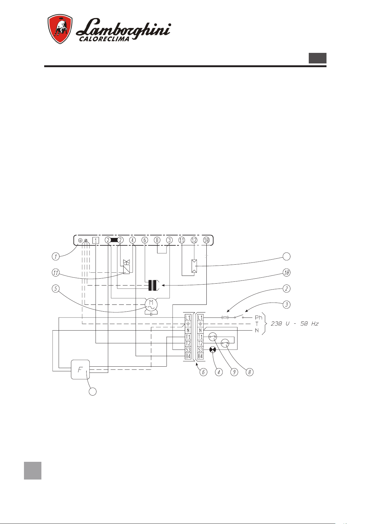
COLLEGAMENTI ELETTRICI
LMO 14
16
7
AVVERTENZE
- Non scambiare il neutro con la fase
- Eseguire il collegamento ad un efcace impianto di terra.
- La linea di alimentazione elettrica al bruciatore deve essere provvista di un interruttore omnipolare con apertura tra i contatti di almeno 3 mm
- Il collegamento della terra alla morsettiera del bruciatore deve essere eseguito con un cavo
più lungo di almeno 20 mm rispetto ai cavi delle fasi e del neutro
- rispettare le norme della buona tecnica ed osservare scrupolosamente le norme locali vigenti
N.B. È necessario osservare scrupolosamente la buona norma che indica il collegamento di
massimo due cavi per morsetto.
M
ECO 15
ECO 20
Page 13

13
IT
ECO 15/2
LMO 24
1
5
4
3
2
1
11
12
13
7
10
15
14
3
2
8
9
4
6
5
16
L1
N
230 V
50 Hz
L1
N
L1
N
T2
S3
T1
B4
L1
N
T2
S3
T1
B4
1°
2°
M
ECO 20/2
Legenda
1 Apparecchiatura automatica di comando e controllo
2 Fusibile 3A
3 Interruttore generale
4 Lampada blocco a distanza
5 Motore bruciatore
6 Spina di allacciamento linea ed apparecchiatura ausiliaria
7 Fotoresistenza
8 Termostato ambiente
9 Termostato caldaia
10 Trasformatore di accensione
11 Elettrovalvola I° stadio
12 Elettrovalvola II° stadio
13 Servomotore comando apertura aria
14 Termostato autoregolazione
15 Morsettiera ausiliaria
16 Filtro
Page 14

14
IT
REGOLAZIONI
REGOLAZIONE ARIA (ECO 15-20)
Il dispositivo a vite micrometrica (13), di accessibilità immediata permette una regolazione dell’aria
in mandata molto ne, stabile e precisa.
Dopo aver allentato la ghiera (12) ruotare la vite
in senso orario per ridurre l’apertura della farfalla;
viceversa ruotarla in senso antiorario per aumentarla.
REGOLAZIONE CANOTTO PORTA UGELLO
La conformazione particolare della bocca fuoco e
del disco deettore, la cui posizione è regolabile
anche a bruciatore funzionante, permette l’otti-
mizzazione dei parametri di combustione su tutta
la gamma di portata del bruciatore e nelle condi-
zioni più critiche di funzionamento. Ruotando la
vite (17) in senso antiorario si ottiene l’avanza-
mento del canotto porta ugello ed un maggiore
passaggio di aria attorno al disco deettore; viceversa ruotando la vite in senso orario si riduce il
passaggio di aria.
M
REGOLAZIONE PRESSIONE POMPA ECO 15 - ECO 20
La pressione della pompa è tarata in stabilimento al valore di 12 Kg/cm2. Nel caso
tuttavia fosse necessario è possibile effettuare la variazione di pressione ruotando la
vite (42). Per vericare il valore di pressione raggiunta occorre montare un manometro sull’attacco (27).
REGOLAZIONE PRESSIONE POMPA ECO 15/2 - ECO 20/2
La pressione della pompa è tarata in stabilimento al valore di 10 Kg/cm2 per il 1°
stadio e di 18 Kg/cm2 per il 2° stadio. Nel caso tuttavia fosse necessario è possibile
effettuare la variazione di tali valori di pressione ruotando le viti (61) per il 1° stadio e
(42) per il 2° stadio. Per vericare i valori di pressione raggiunti occorre montare un
manometro sull’attacco (27).
N.B. Con fondo scala di 30 kg/cm2 il campo di lavoro della pompa è min.7-max.14 kg/cm2.
Page 15

15
IT
REGOLAZIONE ARIA SERVOCOMANDO (ECO 15/2-20/2)
Nel motoriduttore l’azionamento dei controlli ausiliari e di ne corsa è ottenuto con
camme facilmente accessibili e regolabili la cui taratura è facilitata da una scala graduata.
TARATURA DEL PUNTO DI SCATTO DEI CONTATTI
Avvertenze generali:
CAMMA V (2 Stufe) - Camma per la posizione di apertura massima della serranda
(potenza massima con entrambi gli stadi in funzione).
CAMMA IV (1 Stufe) - Camma per la posizione di apertura minima della serranda (potenza minima con il solo 1° stadio in funzione).
CAMMA II-III (MV1-MV2) - Camma ausiliaria per il consenso all’apertura della valvola
del 2° stadio.
AVVERTENZE PRATICHE PER LA REGOLAZIONE DEL MOTORIDUTTORE
Il motoriduttore è tarato in sede di collaudo con le seguenti posizioni:
CAMMA V (2 Stufe) : posizionata a 90°-120° circa.
CAMMA IV (1 Stufe) : posizionata in modo che la serranda si trovi a 25°÷50°.
CAMMA II-III (MV1-MV2): posizionata in modo che l’elettrovalvola del 2° stadio si apra
quando la serranda si trova a 60°÷80°.
Modiche a questa taratura in sede di installazione sono leggibili anche a bruciatore in
funzione agendo sulle viti di regolazione delle camme.
Avvitando le viti si aumenta l’angolo di posizionamento e intervento delle camme.
CAMMA II-III (MV1-MV2)
CAMMA IV (1° stadio)
CAMMA V (2° stadio)
Viti di regolazione
Page 16

16
IT
INSTALLAZIONE
13
12
PRIMA DELLA MESSA IN FUNZIONE DEL BRUCIATORE È BENE ASSICURARSI CHE:
- Bruciatore ed apparecchiatura di comando siano collegate a terra.
- L’ugello montato sul bruciatore sia di portata idonea alla caldaia.
- Il canotto portaugello (10) sia montato con il segno “O” rivolto verso l’alto.
- Nel serbatoio ci sia olio combustibile e le saracinesche siano aperte.
- Il fusibile di protezione circuito elettrico sia di giusto valore.
- I termostati ambiente e caldaia siano regolati alla temperatura desiderata.
- L’eventuale interruttore sul termostato ambiente sia in chiusura.
- La vite di regolazione aria consenta l’apertura della farfalla.
MESSA IN FUNZIONE
- Premere il pulsante dell’apparecchiatura
- Dopo il tempo di preaccensione, il bruciatore si mette in funzione e resta acceso no
a che non si è raggiunta la temperatura prestabilita sull’apparecchiatura di comando
che interverrà per prima (termostato caldaia, termostato ambiente, ecc.). Durante il
normale funzionamento il bruciatore si arresta soltanto per l’intervento degli apparec-
chi di comando o di controllo.
- Regolare la amma agendo opportunamente; sia sulla regolazione dell’aria tramite la
vite (13) e relativa ghiera (12), che sull’avanzamento o arretramento del canotto portaugello (10); per quest’ultima regolazione agire sulla vite (16).
- Si consiglia di avanzare il canotto “+” per portate elevate o prossime alla portata massima ed arretrarlo “-” per portate ridotte.
N.B.: Se il bruciatore non si mette in funzione, controllare che sia avvenuto l’innesco
della pompa e, in caso contrario, provvedere manualmente svitano la vite attacco manometro e riavvitandola non appena si denota la fuoriuscita dell’olio combustibile dal
foro.
M
Page 17

17
IT
APPARECCHIATURA
M
APPARECCHIATURA LMO
Il pulsante di sblocco dell’apparecchiatura è l’elemento principale per poter accedere a tutte le
funzioni di diagnostica (attivazione e disattivazione), oltre a sbloccare il dispositivo di comando
e controllo.
Il pulsante di sblocco è corredato di un led multicolore che da l’indicazione dello stato del
dispositivo di comando e controllo sia durante il funzionamento che durante la funzione di
diagnostica.
INDICAZIONI DELLO STATO DELL’APPARECCHIATURA
Tabella di riepilogo
Condizione Sequenza colori
Condizioni di attesa, altri stati intermedi Nessuna luce
Preriscaldo olio “on” tempo di attesa 5s.max Giallo
Fase di accensione Giallo intermittente
Funzionamento corretto Verde
Funzionamento non corretto, intensità di corrente rilevatore amma
inferiore al minimo ammesso
Diminuzione tensione di alimentazione Giallo Rosso alternati
Condizione di blocco bruciatore Rosso
Segnalazione guasto (vedere tabella diagnosi) Rosso intermittente
Luce parassita prima dell’accensione del bruciatore Verde Rosso alternati
Lampeggio veloce per diagnostica Rosso lampeggiante rapido
Verde intermittente
In caso di blocco bruciatore nel pulsante di blocco sarà ssa la luce rossa. Premendo il pulsante trasparente si procede allo sblocco del dispositivo di comando e controllo. Premendo per più di 3 sec. la fase
di diagnosi verrà attivata (luce rossa con lampeggio rapido), nella tabella sottostante viene riportato il
signicato della causa di blocco o malfunzionamento in funzione del numero di lampeggi (sempre di co-
lore rosso). Premendo il pulsante di sblocco per almeno 3 sec. si interromperà la funzione di diagnosi.
DIAGNOSI DELLE CAUSE DI MALFUNZIONAMENTO E BLOCCO APP. LMO
Indicazione ottica Possibili cause
Assenza di segnale di amma
- malfunzionamento valvole combustibile
2 lampeggi
3 lampeggi
4 lampeggi
5 lampeggi
6 lampeggi
7 lampeggi
8 lampeggi
9 lampeggi
10 lampeggi
- malfunzionamento rilevatore amma
- difettosità nella taratura del bruciatore, assenza di combustibile
-mancata accensione
Libero
Luce estranea all’accensione
Libero
Libero
Assenza di segnale di amma durante il funzionamento
- malfunzionamento valvole combustibile
- malfunzionamento rilevatore amma
- difettosità nella taratura del bruciatore, assenza di combustibile
Anomalia del tempo preriscaldamento del combustibile
Libero
Errori di collegamento elettrico o danni all’apparecchiatura
Page 18

18
IT
MANUTENZIONE
M
ATTENZIONE: tutte le operazioni devono essere eseguite dopo aver tolto corrente
mediante l’interruttore generale ed aver slato la spina. Togliendo il coperchio del bruciatore è possibile effettuare le seguenti operazioni di verica e pulizia.
FOTORESISTENZA
Slarla e pulire accuratamente la parte sensibile. Per la pulizia usare panni asciutti e
puliti. Nel rimontarla vericare che sia ben agganciata.
UGELLO
Slare i cavi di alta tensione dal lato trasformatore, la fotoresistenza, svitare il raccordo
tubo mandata gasolio ed il raccordo sulla pompa combustibile; svitare le viti di ssaggio coperchietto e, ruotando quest’ultimo in senso antiorario, estrarre l’insieme canotto
portaugello). Slare i cavi alta tensione degli elettrodi, allentare la vite di bloccaggio
supportino, slare il supporto porta disco deettore-elettrodi e svitare quindi l’ugello.
Una buona pulizia dell’ugello si ottiene smontando il ltro e pulendo i tagli ed il foro di
polverizzazione con benzina. Non usare in ogni caso attrezzi che possano rovinare le
superci interne.
FILTRO DELLA POMPA COMBUSTIBILE
Chiudere la saracinesca sull’aspirazione, smontare il coperchio della pompa, estrarre
la cartuccia a rete, lavarla con benzina e rimontare il tutto accuratamente.
ELETTRODI DI ACCENSIONE (4-5)
Effettuare la pulizia possibilmente senza variare la loro posizione rispetto al disco de-
ettore; nel caso ciò accadesse rispettare in fase di montaggio le dimensioni indicate
come in gura.
ECO 15 - 15/2
ECO 20 -20/2
ECO 15 - 15/2 -20/2
Legenda
A 1 ÷ 4
B 4 ÷ 5
C 8 ÷ 11
ECO 20
Page 19

19
IT
FILTRO SULLA TUBAZIONE - POSIZIONAMENTO VENTOLA
ATTENZIONE: in caso di pericolo togliere corrente dall’interruttore generale e chiudere l’afusso del combustibile tramite l’apposita saracinesca.
Chiudere la saracinesca sull’aspirazione e, secondo il tipo, procedere ad una accurata
pulizia della parte ltrante. Per una verica della pulizia della ventola della coclea della
serranda aria oppure per un controllo dell’insieme testa di combustione è sufciente
operare nel modo seguente:
- Togliere il coperchio (23) allentando la vite (22);
- Allentare completamente le viti inferiori (32);
- Allentare anche la vite centrale;
- Allentare parzialmente le viti superiori (14);
- Sganciare sollevandola la piastra porta componenti (34) ed agganciarla nell’apposita
sede.
In questo modo si possono vericare le condizioni di pulizia degli organi interni del bruciatore ed eventualmente effettuare le operazioni di sostituzione del gruppo motoreventola.
In fase di montaggio del gruppo vericare che sia rispettata la quota indicata :
Page 20

IRREGOLARITA’ DI FUNZIONAMENTO
DIFETTO CAUSA RIMEDIO
Mancanza di energia elettrica
Il bruciatore non si avvia
Non arriva combustibile al bruciatore
M
Controllare i fusibili della linea di
alimentazione. Controllare la linea dei termostati.
Controllare l’apertura dei dispositivi d’intercettazione posti lungo
la tubazione di alimentazione
Il bruciatore si avvia, non si ha
formazione di amma quindi va
in blocco
Il bruciatore si avvia, si ha formazione di amma quindi va in
blocco
Le valvole del combustibile non
aprono
Non c’é scarica tra le punte degli
elettrodi
Mancata o insufciente rilevazione della amma da parte della
fotoresistenza
Controllare il funzionamento delle valvole
Controllare il funzionamento del
trasformatore d’accensione, controllare il posizionamento delle
punte degli elettrodi
Controllare il posizionamento
della fotoresistenza
IT
20
Page 21

Congratulations...... on your excellent choice.
Thank you for choosing our products.
LAMBORGHINI CALORECLIMA is daily committed to seeking innovative technical solutions to satisfy every need.
Constant presence of our products on the Italian and international markets is assured
by a widespread network of Agents and Dealers assisted by “LAMBORGHINI SERVICE” (Technical Service) who assures qualied service and maintenance of the boiler.
CONFORMITY
The ECO burners are in conformity with:
• Electromagnetic Compatibility Directive 2004/108/CE
• Low Voltage Directive 2006/95/CE
For the production serial number, refer to the technical data plate of the boiler.
INDEX
GENERAL STANDARDS 22
TECHNICAL SPECIFICATIONS 25
WORK CURVES 25
INSTALLATION ON TO THE BOILER 26
WORKING CYCLE 28
WIRING 29
ADJUSTMENTS 31
INSTALLATION 33
EQUIPMENT 34
MAINTENANCE 35
OPERATING IRREGULARITIES 37
Paragraph of interest
for the user
U
M
Paragraph of interest
for the technician
ENGLISH
UK
21
Page 22

22
UK
GENERAL STANDARDS
This manual is an integral and essential part of the product and must be given to the
installer.
Read the warnings given in this manual as they supply important indications regarding
installation, use and maintenance safety.
Keep this manual carefully for future reference. The burner must be installed in compliance with the Standards in force, according to the manufacturer’s instructions and
by qualied staff Incorrect installation can cause injury/damage to persons, animals or
objects, for which the manufacturer cannot be held responsible.
This appliance must only be destined for the use for which it was expressly declared.
Any other use must be considered improper and therefore dangerous.
The manufacturer is not liable for any damage caused by improper, incorrect or unre-
asonable use.
Before carrying out any cleaning or maintenance, disconnect the appliance from the
mains power supply by acting on the system switch or via the relevant shut-off ele-
ments.
M
U
In the case of breakdown and/or bad functioning of the appliance, deactivate it and do
not attempt repairs or direct interventions.
Only contact qualied professional staff.Any product repairs must only be performed
by an after-sales centre authorised by the manufacturer, using original spare parts.
Failure to comply with the above can compromise appliance safety.
In order to guarantee the efciency of the appliance and its correct functioning, it is
indispensable to follow the manufacturer’s indications.
Have qualied professional staff perform periodic maintenance of the appliance.Whenever the appliance is no longer to be used, the parts that may become a potential
source of danger must be made harmless.
Before commissioning the burner, have qualied staff check:
a) that the plate data are those requested by the gas electricity mains supplies;
b) that burner calibration is compatible with boiler power;
c) that the ow of combustion agent air and the evacuation of ue gases take place
correctly according to Standards in force;
d) that aeration and normal maintenance of the burner are guaranteed.
Before performing any intervention that envisions disassembly of the burner or opening of the inspection access points, disconnect the electric current.
Do not deposit containers of inammable substances in the room where the burner is
situated.
Page 23

23
UK
The burner room must have openings towards the outside in compliance with local
Standards in force. If in doubt relative to the circulation of air, rst of all we recommend
that the CO2 value is measured, with the burner functioning at maximum ow rate and
the room ventilated, only via the apertures destined to feed air to the burner and
then by measuring the CO2 value again, with the door open.The value of CO2 measured in both cases must not change in a signicant manner.
If there are more than one burner and fan in the same room, this test must be performed with all appliances functioning simultaneously.
Never obstruct the air apertures of the burner room, the burner fan intake apertures
and any air duct or ventilation grid and external dissipations, with the purpose of pre-
venting:
- the formation of toxic/explosive gas mixtures in the air of the burner room;
- combustion with insufcient air, from which dangerous, costly and polluting functio-
ning occurs.
The burner must always be protected from rain, snow and freezing.
The burner room must always be kept clean and free from volatile substances, which
could be sucked inside the fan and block the interior pipes of the burner and the combustion head. Dust is extremely dangerous, especially if this can deposit on the fan
blades, where it will reduce ventilation and produce pollution during combustion. The
dust an also accumulate on the rear part of the ame stability disc in the combustion
head and cause a poor air/fuel mixture.
The burner must be fed with the type of fuel for which it has been set-up as indicated
on the data plate and in the technical features supplied in this manual. Moreover, it
must be supplied with all control and safety devices requested by local regulations in
force. Pay great care that no external material enters the line during installation.
Make sure that the electric power supply used for the connection is in compliance with
the features indicated on the data plate and in this manual.Make an electric plant with
an effective connection to an earth plant, in compliance with Standards in force. The
earth cable must be a couple of cm. longer that the phase and neutral wire.
If in doubt regarding efciency, it must be checked and controlled by qualied staff.Never exchange the neutral and phase cables.The burner can be connected to the mains
electricity with a plug-socket connection only if this is equipped in a way that the coupling conguration prevents the inversion of phase and neutral.Install an omnipolar
switch with opening between contacts of at least 3mm upstream from the appliance as
requested by the existing legislation.
The entire electric system and in particular all cable sections, must be suitable for the
maximum absorbed power value indicated on the appliance data plate and in this ma-
nual.
If the burner power supply cable is faulty, it must only be replaced by qualied staff.
Never touch the burner with wet body parts or without wearing shoes.
Page 24

24
UK
Never stretch (force) power supply cables and keep them away from heat sources.The
length of the cables used must allow the burner and any boiler door to be opened.
The electric connections must be made exclusively by qualied staff and the regulations in force on the subject of electricity must be respected.After all packaging material has been removed, control the contents and ensure that these have not been
damaged in any way during transport.
If in doubt, do not use the burner and contact the supplier.
The packaging materials (wooden cages, cardboard, plastic bags, expanded materials, staples, etc...) represent a form of pollution and potential risk if left everywhere.
Collect them and dispose of them in a suitable manner (in a suitable place).
The entire electric system and in particular all cable sections, must be suitable for the
maximum absorbed power value indicated on the appliance data plate and in this ma-
nual.
If the burner power supply cable is faulty, it must only be replaced by qualied staff.
Never touch the burner with wet body parts or without wearing shoes.
Never stretch (force) power supply cables and keep them away from heat sources.The
length of the cables used must allow the burner and any boiler door to be opened.
The electric connections must be made exclusively by qualied staff and the regulations in force on the subject of electricity must be respected.
After all packaging material has been removed, control the contents and ensure that
these have not been damaged in any way during transport.
If in doubt, do not use the burner and contact the supplier.
The packaging materials (wooden cages, cardboard, plastic bags, expanded materials, staples, etc...) represent a form of pollution and potential risk if left everywhere.
Collect them and dispose of them in a suitable manner (in a suitable place).
Page 25

25
UK
TECHNICAL SPECIFICATIONS
ECO 15
ECO 15/2
ECO 20
ECO 20/2
M U
DESCRiZiOnE
min 83 128 83 119 kW
Output
Fuel consumption 7 - 14,8 11 - 21 7 - 14,8 10 - 20 kg/h
Fuel light oil l.c.v. 10.210 kcal/kg 1.5°E (6cSt) a 20°C
Flex hoses 1/4” lenght 1100 mm (connection 3/8”)
Fuel pump set at 12
Electrical power supply 230/50-60 V/Hz
Condenser 6,3 μF
Ignition transformer 26 / 48 kV/mA
Weight 15 kg
Packaging size 640x335x400 760x360x440 mm
Nozzles * 1,75 - 3,50 2,50 - 5,00 1,75 - 3,00 2,225 - 4,00
max 176 249 176 237 kW
min 72.000 112.000 72.000 102.000 kcal/h
max 151.000 214.000 151.000 204.000 kcal/h
ECO 15
ECO 15/L
ECO 20
ECO 20/L
ECO 15/2 ECO 20/2
1° stage 10
2° stage 18
bar
* All types as long as 60° SOLID CONE
WORK CURVES
M U
The curves shown in the diagram were obtained by performing combustion tests in
accordance with the specications and characteristics of re required by law.
Page 26

26
UK
INSTALLATION ON TO THE BOILER
Fix ange 2 to the boiler using 4 screws 3 interposing the insulation gasket 4 and the
possible insulating cord 5. Insert the burner in the ange so that the draught tube penetrates into the combustion chamber by the length suggested by the boiler manufacturer. Tighten screw 1 to lock the burner in position.
M
POSITIONING THE BURNER
We recommend that you t the burner on the boiler in the position indicated in gures A
and B. Do not assemble in positions C or D otherwise the anti-drip device in the nozzle
holder cannot be used. Above all, positioning here allows good regulation of the air
intake gate and allows its immediate closure when the burner is switched off. Fit the
burner in positions C or D only if absolutely necessary.
IMPORTANT: if the burner is installed in position B the nozzle holder must be rotated
60° so that the notch on the holder is facing upwards. Then lock the burner in place
with the screw and x the attachment plate with the two upper screws.
Page 27

27
UK
FUEL FEED PIPES
M
ASPIRATED SYSTEM
PIPE LENGHT
Diagrams refer to light oil with max viscosity 1.5°E (6 cSt) at 20°C.
GRAVITY-DROP SYSTEM
Key
A Fuel aspiration line
B Fuel lter
C Fuel aspiration line gate
D Flow-stop solenoid valve
E Return line gate
F Return line
G Bottom valve
H Rapid on-off gate with remote control
L One-way check valve
Page 28

28
UK
WORKING CYCLE
M
SINGLE-STAGE:
When switched on the burner motor starts and the 15-second pre-ventilation phase
begins. During this phase the ignition transformer comes on and the inter-electrode arc
is generated. Once pre-ventilation is over the fuel on-off valve opens and the fuel starts
owing out of the nozzle thus igniting a ame. After another 3 seconds (post-ignition
phase) the inter-electrode arc is switched off. If the ame fails to appear within 10 seconds of the end of pre-ventilation the burner is shut down. If the ame accidentally
goes out during routine operation an automatic re-ignition sequence begins. Burner
shutdown is indicated by the boiler system warning light and/or by the room thermostat
indicator. Burner restart is effected by pressing the reset button.
TWO-STAGE:
When switched on the burner motor starts and the 13-second pre-ventilation phase
begins. During this phase the ignition transformer comes on and the inter-electrode
arc is generated. Once pre-ventilation is over the fuel on-off valve opens and the fuel
starts owing out of the nozzle thus igniting a ame. After another 15 seconds (postignition phase) the inter-electrode arc is switched off. If the ame fails to appear within
10 seconds of the end of pre-ventilation the burner is shut down. At the end of the post
ignition time, the servomotor of the air lock is switched ON, thereby causing the air
lock to open. This will supply the fuel selenoid valve tted on the pump, so that gas air
pressure at the nozzle will increase from 10 Kg/cm2 (rst stage) to 18 Kg/cm2 (second
stage). If the ame accidentally goes out during routine operation an automatic reignition sequence begins. Burner shutdown is indicated by the boiler system warning
light and/or by the room thermostat indicator. Burner restart is effected by pressing the
reset button .
ECO 15
ECO 20
ECO 15/2
ECO 20/2
Necessary input signals
Output signals
t1 Pre-ventilation and pre-ignition
t2 Post-ignition
t3 Max safety time
Page 29

29
UK
WIRING
LMO 14
16
7
WARNING:
- Do not invert the neutral with the phase.
- Make the connection to an ef cient earthing system.
- The electrical power line to the burner must be tted with an omnipolar switch with an ope-
ning
of at least 3 mm between the contacts.
- The earth connection to the terminal board of the burner must be made with a cable at least
20 mm longer than the phase and neutral cables.
- Must be workmanlike performed and comply with the regulations in force.
NOTE: Always make sure that no more than two wires are connected to each terminal.
M
ECO 15
ECO 20
Page 30

30
UK
ECO 15/2
LMO 24
1
5
4
3
2
1
11
12
13
7
10
15
14
3
2
8
9
4
6
5
16
L1
N
230 V
50 Hz
L1
N
L1
N
T2
S3
T1
B4
L1
N
T2
S3
T1
B4
1°
2°
M
ECO 20/2
Key
1 Automatic control unit
2 3A fuse
3 Main switch
4 Lock-out warning light
5 Burner motor
6 Mains connection plug and auxiliary devices
7 Photo-resistor
8 Room thermostat
9 Boiler thermostat
10 Ignition transformer
11 1st stage solenoid valve
12 2nd stage solenoid valve
13 Air aperture servomotor
17 Self-adjusting thermostat
15 Auxiliary terminal block
16 Filter
Page 31

31
UK
ADJUSTMENTS
AIR ADJUSTMENTS (ECO 15-20)
The easily accessible micrometric screw device
(13) allows ne, stable, precise adjustment of delivery air. After loosening the crown (12) turn the
screw clockwise to reduce throttle valve aperture:
turn anticlockwise to increase it.
NOZZLE HOLDER ADJUSTMENT
The special shape of the draught tube and the
diffuser, the position of which is adjustable even
when the burner is working, allows optimisation
of combustion parameters right across the burner
owrate range and even in critical working conditions. Turn the screw (17) anticlockwise to bring
the nozzle holder forward and increase airow
around the diffuser. Vice versa, turning the screw
anticlockwise reduces the amount of air passing
through.
M
PUMP PRESSURE ADJUSTMENT ECO 15 - ECO 20
Pump pressure is calibrated at the factory at 12 Kg/cm2. However, should it be necessary, pressure can be adjusted by turning the screw (42). To check the obtained
pressure t a pressure gauge on the pressure takeoff point (27).
PUMP PRESSURE ADJUSTMENT ECO 15/2 - ECO 20/2
Pump pressure is calibrated at the factory at 10 Kg/cm2 for the 1st stage and 18 Kg/
cm2 for the 2nd stage. However, should it be necessary, pressure can be adjusted by
turning the screw (61) for the 1st stage, and screw (42) for the 2nd stage. To check the
obtained pressure t a pressure gauge on the pressure take-off point (27).
N.B.: With a scale range of up to 30 Kg/cm2 the working range of the pump is min 7 - max 14
Kg/cm2.\
Page 32

32
UK
GEARED MOTOR CONTROLLING AIR DELIVERY (ECO 15/2-ECO 20/2)
The geared motor limit switch and auxiliary contacts are triggered by easily accessible
adjustable cams, which can be set against o graduated scale.
SETTING THE CONTACT TRIGGERING POINT
General information:
CAM V (2 Stufe) - Cam controlling air valve fully open position (maz. ring rate with
both stages in operation).
CAM IV (1 Stufe) - Cam controlling minimum air ow condition (min. ring rate 1st
stage
only in operation).
CAM II-III (MV1-MV2) - Auxiliari cam activating the 2nd stage valve.
RECOMMENDATIONS TO PROPERLY SET THE GEARED MOTOR
The geared motor is set upon testing as follows:
CAM V (2 Stufe) : is set on approx 90°-120°
CAM IV (1 Stufe) : is set on approx 25°÷50°.
CAM II-III (MV1-MV2): is set in such a way that the 2nd stage valve opens when the air
shut-off valve is at 60°÷80°.
Changes to this calibration during installation are legible even when the burner is in
operation by acting on the adjusting screws of the cams.
Tightening the screws increases the angle and positioning of the cams.
CAMMA II-III (MV1-MV2)
CAMMA IV (1 Stage)
CAMMA V (2 Stage)
Adjusting screws
Page 33

33
UK
INSTALLATION
13
12
BEFORE STARTING THE BURNER ALWAYS CHECK THE FOLLOWING:
- Burner and control unit have a proper earth connection.
- The on-burner nozzle (3) has a ow-rate suitable for the boiler.
- The nozzle holder (10) is tted with the “O” marking facing upwards
- That there is fuel in the tank and the gates are open.
- The fuse on the electrical circuit is rated.
- The room and boiler thermostats are set to the desired temperature.
- The switch on any room thermostat is set.
- The main switch contacts are open.
- Any other control device has contacts closed.
- The air adjustment screw allows the throttle valve to open.
M
START-UP
- Reset by acting on the push-button.
- Power up by turning the main switch to ON. After the pre-ignition time has elapsed the
burner starts running and stays on until the temperature set on one of the control devices causes the latter to trip (boiler thermostat, room thermostat etc.). During routine
operation the burner only shuts down when a control device is tripped.
- Adjust the ame by acting on both the air ow via the screw (13) and relative crown
(12) and on forward-rearward excursion of the nozzle holder (10). To adjust the latter
act on the screw (17).
- It is recommended that you bring the holder forward (+) for high or near-maximum
ow-rates and shift it back (-) for low ow-rates.
N.B. If the burner fails to start up check that the pump has been primed: if it has not,
act manually by undoing the gauge attachment screw and then screwing it back in as
soon as you notice fuel exiting the hole.
Page 34

34
UK
EQUIPMENT
M
LMO EQUIPMENT
The release pushbutton on the equipment is the main component for accessing all the diagnostic functions (activation and deactivation) as well as for releasing the control and checking
device.
The release pushbutton has a multicoloured led which indicates the state of the control and
checking device during operation and when the diagnostic function is in use.
EQUIPMENT STATE INDICATORS
Description
Condition Colour sequence Colour sequence
Standby, other intermediate states No light
Fuel preheating “on”, waiting time 5s.max Yellow
Ignition stage Yellow, ashing Yellow, ashing
Correct operation Green
Incorrect operation, current level of
ame detector below permitted minimum Green, ashing
Drop in voltage Alternating yellow red
Burner lock out Red
Fault Red, ashing
Stray light before burner ignition Alternating green red
Rapid ashing for diagnostics Red, rapid ashing
Green, ashing
If the burner is locked out, there will be a steady red light on the lock out pushbutton.
By pressing the transparent pushbutton, the control and checking device will be released.
By pressing it for more than 3 seconds, the diagnosis stage will be activated (red light ashes rapidly).
The table below describes the causes of the lock out or fault in relation to the number of ashes (always
red). The diagnosis function is interrupted by pressing the release button for at least 3 seconds.
DIAGNOSIS OF LMO EQUIPMENT FAULTS AND LOCK OUT
Visual indication Possible causes
No ame signal
- Faulty fuel valves
2 ashes
3 ashes
4 ashes
5 ashes
6 ashes
7 ashes
8 ashes
9 ashes
10 ashes
- Faulty ame detector
- Incorrect burner setting, no fuel
- No ignition
Not used
Stray light on ignition
Not used
Not used
No ame signal during operation
- Faulty fuel valves
- Faulty ame detector
- Incorrect burner setting, no fuel
Anomalies in fuel preheating time
Not used
Incorrect electrical connection or damage to equipment
Page 35

35
UK
MAINTENANCE
M
WARNING: all work must only be done after rst cutting power via the main switch and
after removing the plug. By removing the cover from the burner it is possible to carry
out the following checks and cleaning tasks.
PHOTORESISTOR
Remove and clean the sensor carefully. Use a clean, dry cloth. When replaced make
sure it is properly attached.
NOZZLE
Remove the high voltage wires on the transformer side and the photo-resistor, unscrew
the coupling and the other coupling on the fuel pump. Unscrew the cover attachment
screws and extract the nozzle holder set by rotating the cover anticlockwise. Remove
the high voltage wires on the electrodes, loosen the holder lock screw, remove the diffuser/electrodes holder and then unscrew the nozzle. To clean the nozzle thoroughly
disassemble the lter and clean the slots and the spray hole with petrol. Never use
tools which might damage internal surfaces.
FUEL PUMP FILTER
Close the fuel aspiration gate, remove the pump cover, take out the mesh cartridge,
wash it with petrol and re-assemble carefully.
IGNITION ELECTRODES (4-5)
Clean the electrodes without varying their position with respect to the diffuser; if you
accidentally move them observe the dimensions given in g. when re-assembling.
ECO 15 - 15/2
ECO 20 -20/2
ECO 15 - 15/2 -20/2
Legenda
A 1 ÷ 4
B 4 ÷ 5
C 8 ÷ 11
ECO 20
Page 36

36
UK
PIPE FILTER - POSITIONING FAN
Close the fuel aspiration gate and, depending on the type, proceed with thorough cleaning of the ltration component. To check whether the air gate fan is clean or to check
the combustion head proceed as follows:
- Remove the cover (23) by loosening the screw (22).
- Loosen the lower screws (32) completely.
- Loosen the central screw too.
- Parzially loosen the upper screws (14) too.
- Release by raising the component support plate (34) and hook it in its seat as illustrated in g. 16.
Doing the above provides the conditions needed to check whether the internal burner
parts are clean and, where necessary, to replace the motor-fan unit. When re-assembling make sure that you observe the gap illustrated in g. 15.
WARNING: in the event of a dangerous situation cut power by turning the main switch
to OFF and stop fuel ow via the relative gate.
Page 37

37
UK
OPERATING IRREGULARITIES
PROBLEM CAUSE SOLUTION
There is no electricity.
The burner does not start
Fuel is not arriving to the burner. Check the fuel line.
The fuel valve is not open Check operation of valves
The motor turns but there is
no ame and the system shuts
down.
There is no spark from the electrodes.
M
Check the fuses.
Check the thermostats (Room
tem perature, Furnace and safety).
Check the correct position of the
points and clean them.
The motor turns but there is
a ame and then the system
shuts down.
Lack of or insufcient ame detection by the photocell
Clean the photo resistance.
Clean or change the choke.
Page 38

38
UK
Page 39

39
UK
Page 40

Le illustrazioni e i dati riportati sono indicativi e non impegnano. La Lamborghini Calor
si riserva il diritto di apportare senza obbligo di preavviso tutte le modiche che ritiene
più opportune per l’evoluzione del prodotto.
The illustrations and data given are indicative and not binding. Lamborghini Calor reserves the right to make all modications it deems appropriate for improvement of the
product without forewarning.
LAMBORGHINI CALOR S.p.A
VIA STATALE, 342
Casella postale 46
44047 DOSSO (FERRARA)
ITALIA
TEL. ITALIA 0532/359811 – EXPORT 0532/359913
FAX ITALIA 0532/359952 – EXPORT 0532/359947
Cod. 97.00524.0 05/12
 Loading...