

Page 1

02 - DRIVING TORQUES
Workshop manual - Diablo 6.0
02-1
Page 2

CONTENTS
Engine
Engine control unit
Clutch
Gearbox
Propeller shaft
Front differential
Rear differential
Brakes
Suspension and steering
Bodywork
Workshop manual - Diablo 6.0
02-2
Page 3

Engine
Workshop manual - Diablo 6.0
No. Description
1 Screws securing timing chain shoes on crankcase 30
2 M8 nuts securing engine stands to crankcase 28
3 Main oil duct closing caps 70
4 Screws securing connecting rod caps Engine oil
Clamping: torque + angle
Check: elongation torque at 60°
5 Oil pump filter M8 nuts 30
6 M8 nuts securing front cover to oil pump 30
7 M12 nuts securing crankshaft lower support on crankcase
first tightening
full tightening
8 M8 nuts securing crankshaft lower support on crankcase 30
9 M8 screw securing crankshaft lower support to crankcase (timing side) 30
Torque
15 + 60°
± 0.015 mm
0.115
55
40
90
[Nm]
Notes
± 10%
± 2°
÷ 85
± 7%
± 3% Molycote 1000
± 10% Molycote 1000
See figure 1 for
tightening order
± 10%
10 M8 nuts securing timing box to crankcase 30
11 Timing box to crankshaft screws 28
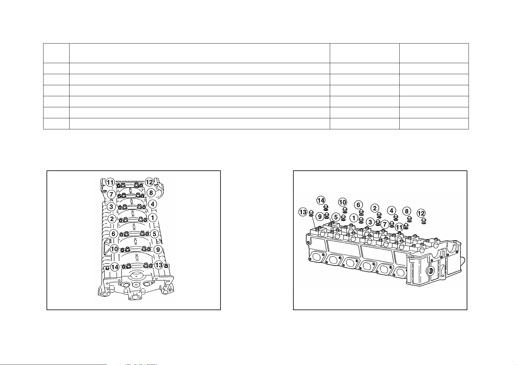
12 Cylinder head nuts 108 Molycote 1000
13 Not used
14 Driving pulley to crankshaft screw 140
15 Not used
16 Spark plug caps 80
02-3
± 10%
± 10%
See figure 2 for
tightening order
Page 4
Workshop manual - Diablo 6.0
No. Description
Torque
[Nm]
17 Nuts securing camshaft supports on cylinder head 9
18 Not used
19 Gear to exhaust timing shaft screws 120
20 Phase variator on intake timing shaft 90
21 Phase variator screws 7
22 Hydraulic tensioners on cylinder head 45
Notes
030201
Fig. 1 – Tightening order for M8 nuts on crankshaft
support
030202
Fig. 2 – Tightening order for cylinder head nuts
02-4
Page 5

Engine control unit
Workshop manual - Diablo 6.0
No. Description
1 Lambda sensor on exhaust 58.8
2 Spark plugs 17.6
3 Delivery couplings on fuel manifold 25
4 Outlet couplings on fuel manifold 25
Clutch
No. Description
1 Mechanism to flywheel securing screws
approach –
tightening 15.5
Torque
[Nm]
Notes
± 2
± 2
Torque
[Nm]
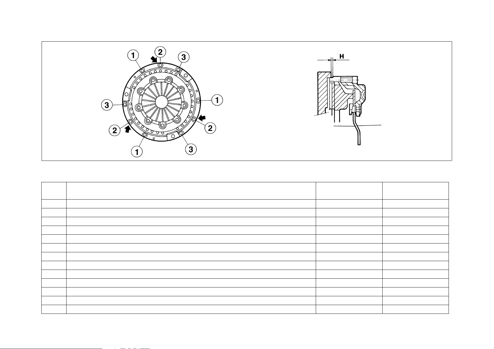
(arrow) to obtain H
Notes
Do not lubricate
See figure 3:
tighten screws 2
÷ 2 mm
H = 1
± 5% See figure 3 for
tightening order
2 Thrust block support sleeve nuts 9.25
3 Flywheel securing screws 39.2
02-5
Page 6
Workshop manual - Diablo 6.0
030203
Fig. 3 – Flywheel mechanism tightening
Gearbox
No. Description
Torque
[Nm]
Notes
1 Shift lever housing screws 20
2 Fork and ratchet screws 29.4
3 Main /driven shaft idle gear ring-nut 230 Molycote 1000
4 Screws securing clutch bell to engine 25
5 Transmission gear ring-nut 180
6 Clutch oil seal flange nuts 9.3
7 Screws securing clutch bell to gearbox 25
8 Screws securing gearbox oil pump cover 29.4
9 Screws securing gearbox oil filter 29.4
10 Rear driving shaft bearing ring-nut 245
11 Turret upper support bolt 140
12 Gearbox upper cover screws 25
13 Front driving flange nut 176
02-6
Page 7

Propeller shaft
Workshop manual - Diablo 6.0
No. Description
Torque
[Nm]
Notes
1 Propeller shaft flange fastening screws 39
2 Front differential axle shaft joint fastening screws 39
3 Rear wheel/differential axle shaft joint fastening screws 69
Front differential
No. Description
Torque
[Nm]
Notes
1 Differential crown fastening screws 70 Loctite 52A70
2 Differential cover fastening screws 30
3 Box hub fastening nuts 30
4 Propeller shaft flange fastening ring 150 Molycote 1000
Rear differential
No. Description
Torque
[Nm]
Notes
1 Differential box cover nuts 50 Molycote 1000
2 Not used
3 Pinion-pinion set flange fastening screws 30 Loctite 52A70
4 Axle shaft flange fastening screws 91.4 Loctite 641
Molycote 1000
5 Differential crown fastening screws 102
6 Crown beaaring pre-load flange fastening nuts 40 Molycote 1000
02-7
Page 8

Brakes
Workshop manual - Diablo 6.0
No. Description
1 Not used
2 Brake shoe fastening screws 115
3 Hydraulic control fitting on shoe 18.5
4 Brake disc to hub fastening screws
5 Male ABS control unit hydraulic fitting 12
6 Female ABS control unit hydraulic fitting 16
Suspension and steering
No. Description
1 Front axle shaft to hub fastening nut 345
2 Front suspension upper arm fastening nut 85
3 Front/rear shock absorber fastening screws 85
4 Rear suspension upper arm fastening nuts 85
5 Front hub bearing fastening ring 490 Loctite 242
Torque
[Nm]
Notes
± 5 Loctite 222
± 1.5 Brake oil
± 1 Lubricating oil
± 2 Lubricating oil
Torque
[Nm]
Notes
± 5
± 5
± 5
± 5
6 Suspension arm ball joint housing on pillar 175
7 Steering arm joint fastening nut 44
8 Front pillar upper/lower joint fastening nut 69
9 Steering arm joint housing on pillar 62.5
10 Lifting system flow separator valve unit fittings 37
11 Steering box fastening screws 45
02-8
± 0.5
± 5 Loctite 270
± 2.5 Loctite 270
Page 9

Bodywork
Workshop manual - Diablo 6.0
No. Description
1 Windscreen wiper arms
Tighten
Settle
Torque
[Nm]
35
30
Notes
02-9
Page 10

10 - ENGINE
Workshop manual - Diablo 6.0
10-1
Page 11

CONTENTS
Workshop manual - Diablo 6.0
DESCRIPTION P. 3
Cylinder numbering and direction of crankshaft rotation
SPECIFICATIONS AND DATA P. 5
Crankshaft
Connecting radius R
Crankcase
Piston liners
Pistons
Piston pin
Piston rings
Tappets
Valve guides (intake and exhaust)
Fitting between valve stem and relevant guide
Valve springs (intake and exhaust)
Engine cooling
REMOVAL AND REFIT P. 22
ASSEMBLY P. 23
COOLING CIRCUIT P. 33
Description
Radiators and electric fans
Thermostatic valve
Radiator removal
Filling up the system
LUBRICATION CIRCUIT P. 36
Description
Thermostatic valve
Oil pump check
Level check and oil replacement
PNEUMATIC UTILITY CONNECTIONS P. 40
CHECKS AND ADJUSTMENTS P. 25
Valve clearance
Locking the phase variator
Position check
Positioning
Timing regulation
Adjustment
Checking
Locking check on phonic wheel for engine timing sensor
10-2
Page 12

Workshop manual - Diablo 6.0
DESCRIPTION
Otto cycle – 4 intake stroke engine, 12 V cylinders at 60°; timing system with 4 valves for each cylinder, double overhead camshaft
controlled by double chain, phase variator on intake, indirect MPI injection (one injector for each cylinder), static electronic ignition
(one coil per cylinder), liquid cooling with double radiator, forced lubrication with oil radiator, exhaust six in two in one with catalyst.
Aluminium alloy and H+T silicon “open deck” type crankcase with wet inserted liners.
Steel alloy liners with Nikasil treated internal surfaces. This treatment ensures a very high surface hardness.
This type of liner cannot be lapped.
Cr Mo hardened and tempered steel crankshaft, the working surfaces are hardened by gaseous nitriding. The crankshaft bearings
are smooth. The main bearing caps are integrated in a block structure to give maximum stiffness.
Each time the crankshaft is undersized, it is most important to restore the surface hardness by the special heat treatment.
Titanium alloy connecting rods with modular head, smooth bearings at big and small ends.
The pistons are in pressed light alloy with three rings, two seals and one oil scraper.
The cylinder heads are aluminium alloy and H+T silicon, with bronze valve guides and cast iron valve seats.
The timing system consists of two overhead camshafts for each cylinder bank, controlled by double chains with phase variator on
the intake shafts.
Motion is transmitted directly from the crankshaft to two gear wheels by means of a double chain. Each of these gear wheels in its
turn controls the two camshafts of each head by means of double chains.
The chain tension is ensured by hydraulic chain tighteners that operate with the lubrication circuit oil.
The cooling system with two cooling radiators is a closed loop system with forced circulation by a centrifugal pump belt driven by
the crankshaft.
The lubrication is forced by a gear pump with a vented gas recycling system and radiator to cool the oil.
10-3
Page 13
Workshop manual - Diablo 6.0
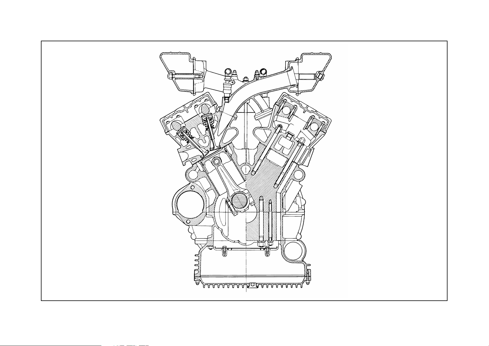
Fig. 1 - Engine cross section
031001
10-4
Page 14
Workshop manual - Diablo 6.0
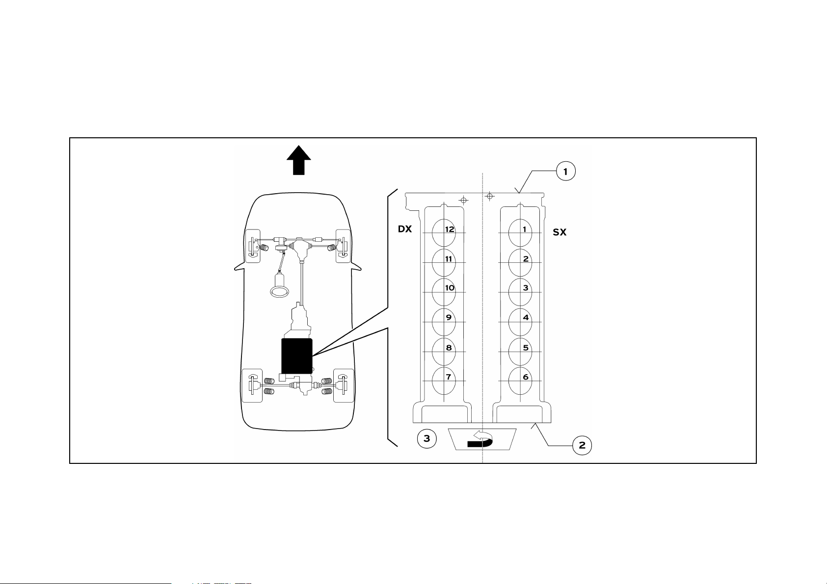
Cylinder numbering and direction of crankshaft rotation
The engine rotation is anticlockwise (as seen from the timing side).
The engine cylinder banks are defined as right and left hand as seen from the flywheel.
The No. 1 cylinder is the first of the left hand cylinder bank near the flywheel, the numbering continues following a U towards the
right hand cylinder bank.
Fig. 2 – Numbering of cylinders
1 Engine flywheel side
2 Timing side
3 Direction of rotation
(counterclockwise from timing side)
181002
4 Travel direction
SX = Left hand cylinder bank (cylinder bank 1-6)
DX = Right hand cylinder bank (cylinder bank 7-12)
10-5
Page 15

Workshop manual - Diablo 6.0
SPECIFICATIONS AND DATA
Crankshaft
Crankshaft end float 0.155 to 0.315
Crankpin and conrod journals surface hardness
HV1 630
Crankpin and conrod journals surface finish 0.2 mm
Crankpins:
Rated diameter D
2nd undersizing
Conrod journals:
Rated diameter d
2nd undersizing
62.966 to 62.979
62.712 to 62.722
45.482 to 45.500
45.236 to 45.246
Shoulders:
Rated width
Oversized thickness
The 1st undersizing is no longer available.
Whenever crankshaft undersizing is performed, it is most important to restore the surface hardness with special treatment of the NITREG type, attaining to these specifications:
temperature: 530 °C
times: rising 4 hours
holding 40 hours
descent 4 hours
depth of nitriding : 0.35 to 0.40 mm
hardness: HV1: 600 to 680
HV10: 550 to 630
white sheet thickness: < 10 microns
40.070 to 40.100
40.578 to 40.608
10-6
Page 16
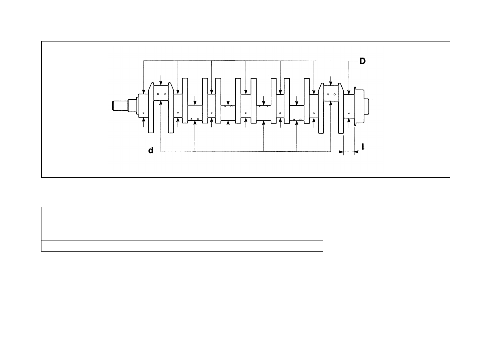
Fig. 3 – Crankshaft
Workshop manual - Diablo 6.0
031003
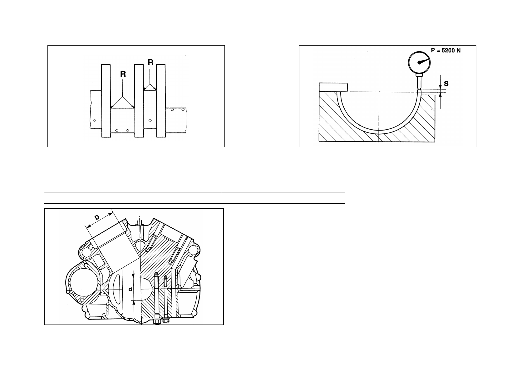
Connecting radius R
Crankpins 2.0 to 2.2
Conrod journals 2.0 to 2.2
Protrusion from crankcase edge (bushing) s 0.125 to 0.150 (*)
Bushing/shaft clearance 0.010 to 0.050
(*) apply a force P=5200 N as indicated in the figure.
10-7
Page 17
Workshop manual - Diablo 6.0
031004
Fig. 4 – Crankshaft Fig. 5 – Crankshaft bearings
Crankcase
Crankpin seat diameter d 66.675 to 66.688
Liner seat diameter D 92.000 to 92.035
031005
Fig. 6 – Crankcase
031006
10-8
Page 18
Workshop manual - Diablo 6.0
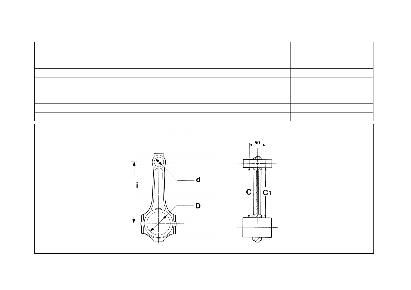
Conrods
Piston pin seat Ø (small end) d 20.020 to 20.030
Conrod bushing seat diameter (big end) D 48.626 to 48.642
Axis parallelism tolerance (piston pin-shaft) C – C1=
± 0.03
Conrod big end width 19.900 to 19.905
Conrod small end width 20.750 to 20.755
Distance between centres i 135.97 to 136.03
Piston pin and conrod small end bushing assembly clearance 0.020 to 0.080
Interference between piston pin bushing and conrod hole 0.050 to 0.096
Conrod journal bearings on crankshaft assembly clearance 0.024 to 0.067
Fig. 7 – Conrods
031007
10-9
Page 19

The big end grooves are to face the crank arms when fitting the conrod-piston group.
If one or more conrods are replaced, it is essential that the spare parts are identical to the originals. (PANKL or LAMBORGHINI).
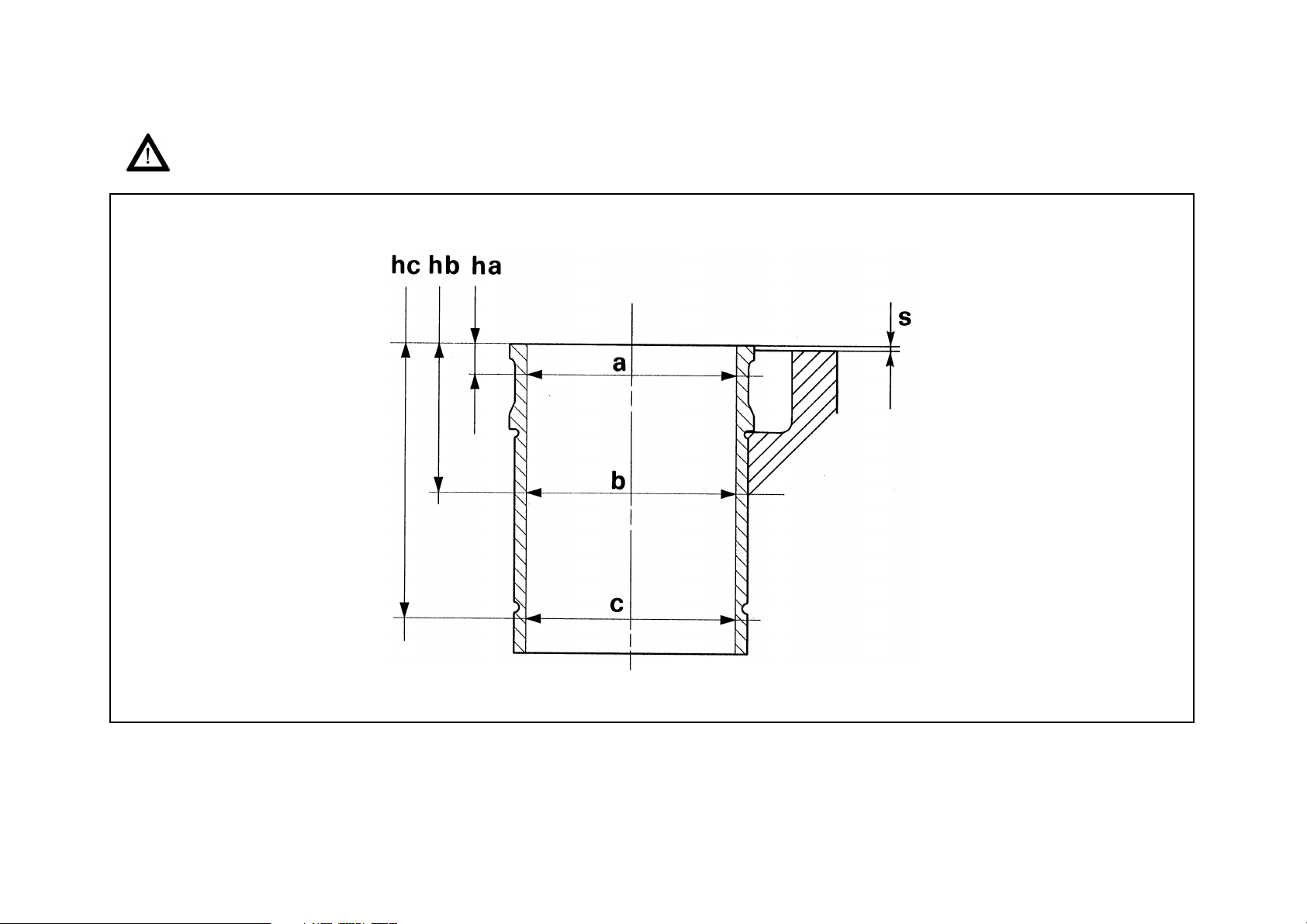
Piston liners
Rated diameter
Group A 86.995 to 86.985
B 87.005 to 86.995
C 87.015 to 87.005
Height ha 5
Diameter a
Group A 86.995 to 86.975
B 87.005 to 86.985
C 87.015 to 86.995
Height hb 60
Diameter b
Group A 89.995 to 86.985
B 87.005 to 86.995
C 87.015 to 87.005
Height hc 110
Diameter c
Group A 87.005 to 86.985
B 87.015 to 86.995
C 87.025 to 87.005
Workshop manual - Diablo 6.0
Liner protrusion from crankcase edge s 0.4 to 0.7 (*)
Maximum taper 0.02
Maximum ovalisation 0.03
Surface roughness 0.3 micron
(*) measure with a liner-stop pre-load P=30 [N]
10-10
Page 20
The liners cannot be shimmed.
Workshop manual - Diablo 6.0
Fig. 8 – Liners
031008
10-11
Page 21

Pistons
Rated diameter
Workshop manual - Diablo 6.0
Group A 86.900
B 86.910
C 86.920
Total height H 47.1
Piston crown-piston pin axis
height H1
Piston pin axis-lower edge
height H2
Step I – slot h height 6.1 to 6.3
Height I slot a 1.230 to 1.250
Height II slot b 1.770 to 1.790
Height III slot c 3.010 to
Pistons must always be coupled with liners belonging to the same group. Pistons and liners belonging to the same
engine must all be of the same group.
29.050 to 29.150
17.8 to 18.0
± 0.009
± 0.009
± 0.009
3.030
10-12
Page 22
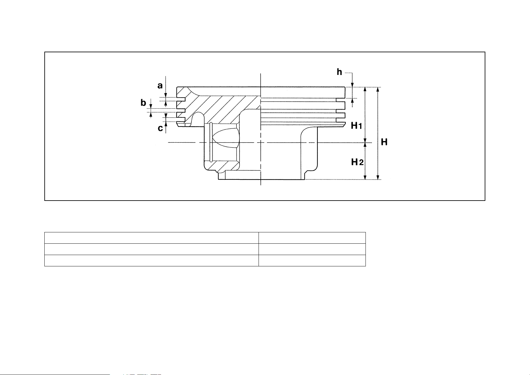
Fig. 9 – Pistons
Workshop manual - Diablo 6.0
031009
Piston pin
Diameter 19.995 to 20.000
Seat diameter 20.010 to 20.016
Piston pin-piston clearance 0.010 to 0.020
10-13
Page 23

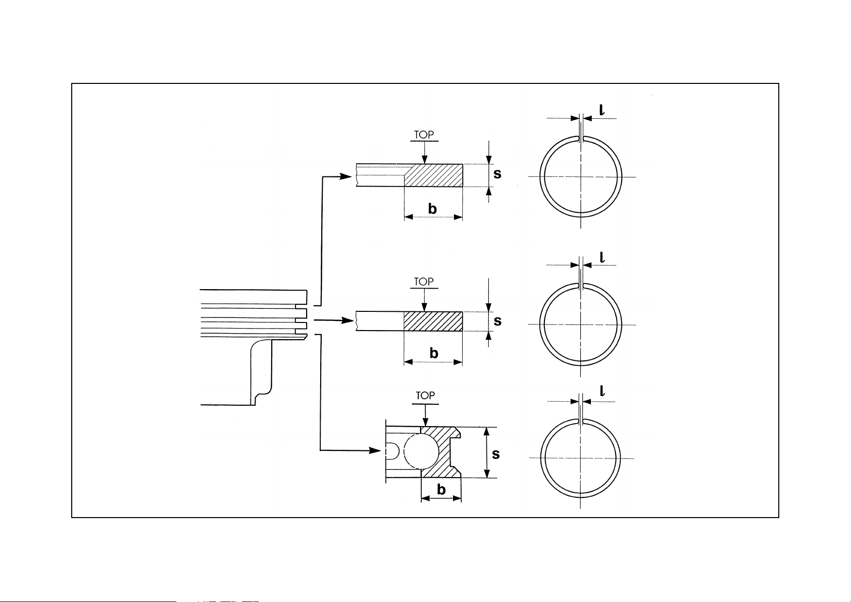
Piston rings
SLOT I
Height s 190 to 1.175
Thickness b 3.70 to 3.45
Gap between ends l 0.20 to 0.40 (*)
Slot-piston ring clearance 0.040 to 0.075
SLOT II
Height s 1.740 to 1.728
Thickness b 3.70 to 3.45
Gap between ends l 0.30 to 0.50 (*)
Slot-piston ring clearance 0.020 to 0.062
Diameter b
SLOT III
Height s 2.990 to 2.975
Thickness b 3.00 to 2.75
Workshop manual - Diablo 6.0
Gap between ends l 0.25 to 0.50 (*)
Slot-piston ring clearance 0.020 to 0.055
(*) measured with piston ring fitted in the liner.
10-14
Page 24
Workshop manual - Diablo 6.0
Fig. 10 – Piston rings
0310010
10-15
Page 25
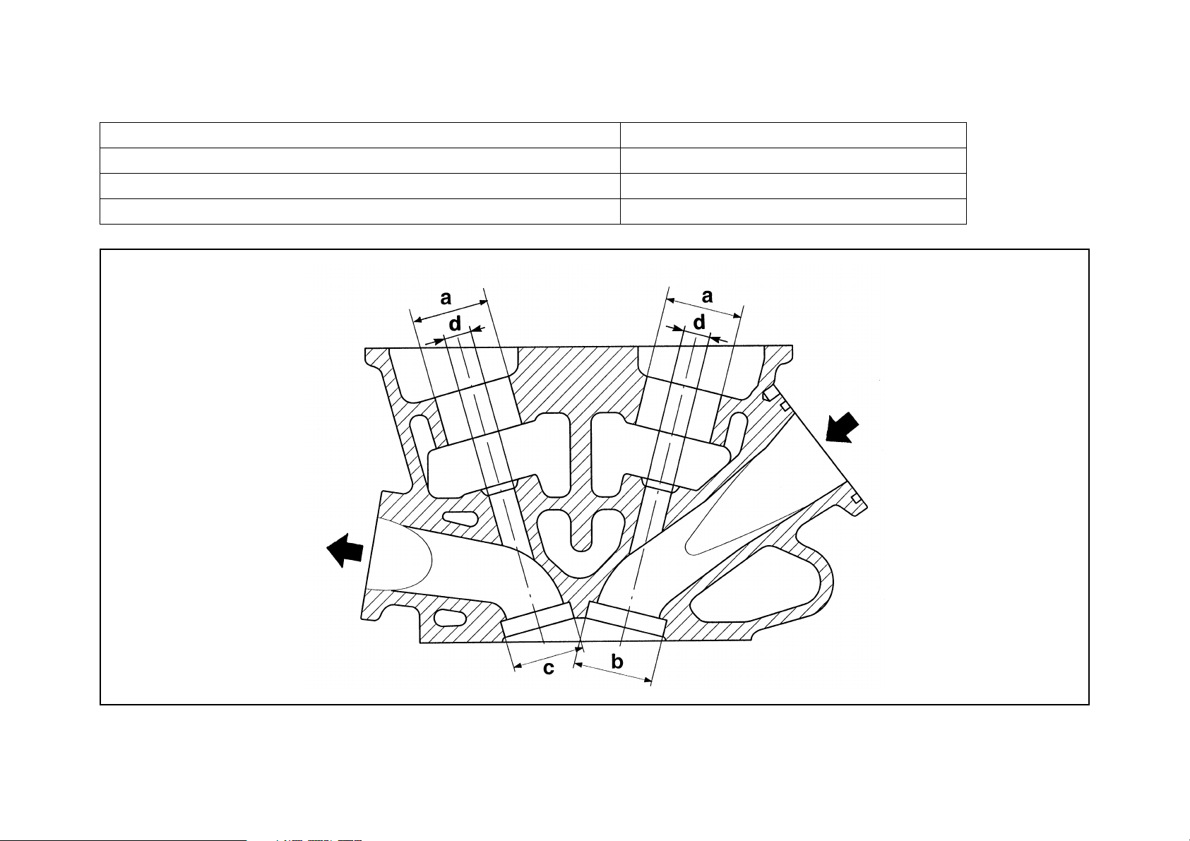
Cylinder heads
Tappet housing diameter (a) 33.015 to 33.030
Intake valve seat housing diameter (b) 30.560 to 30.580
Exhaust valve seat housing diameter (c) 30.560 to 30.580
Valve guide housing diameter (intake and exhaust) (d) 12.00 to 12.018
Workshop manual - Diablo 6.0
Fig. 11 – Cylinder head
0310011
10-16
Page 26

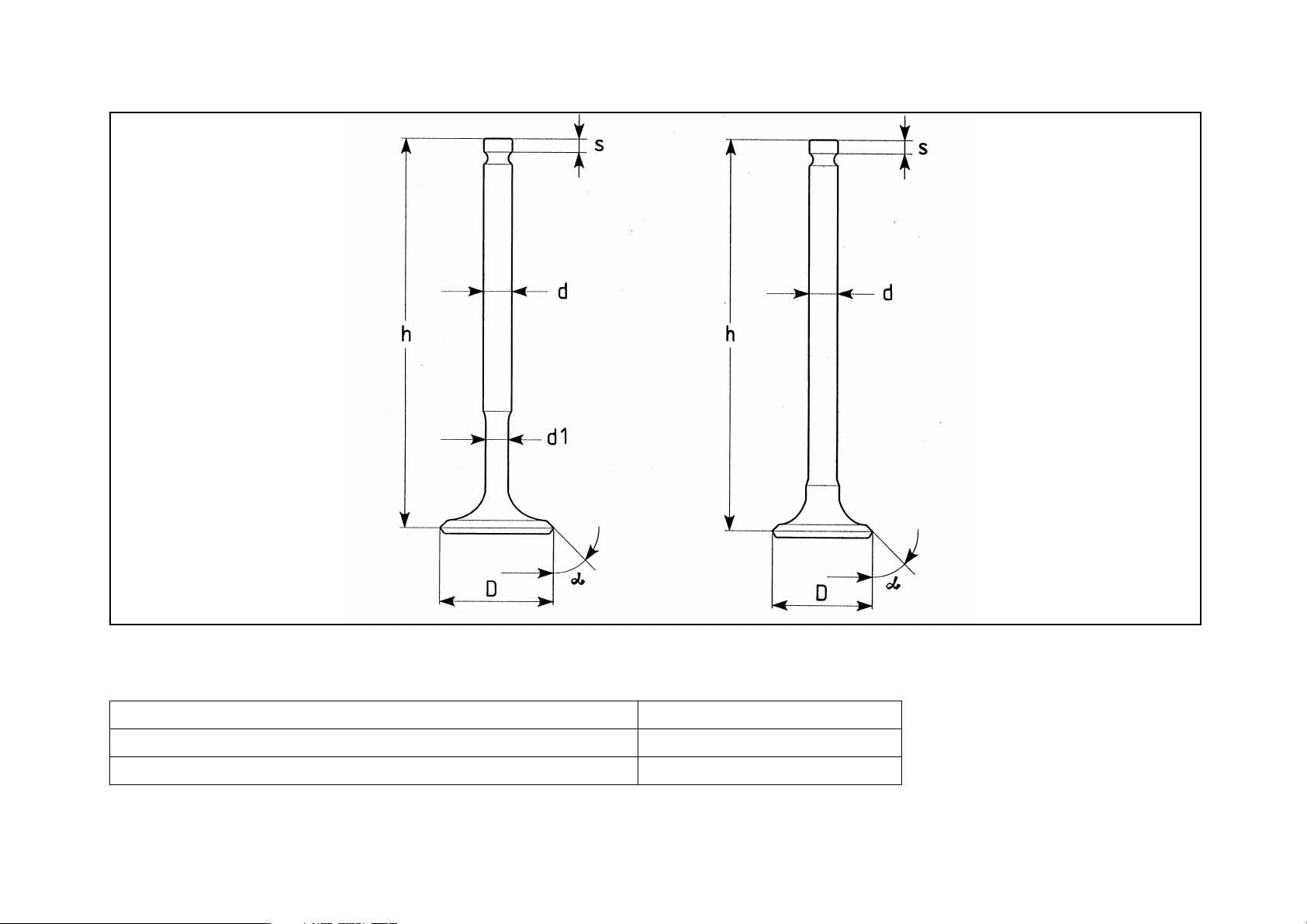
Valves
Intake
Stem diameter d 6.950 to 6.970
Reduced stem diameter d1 6.50 to 6.60
Valve head diameter D 33.3 to 33.5
Workshop manual - Diablo 6.0
Valve seat angle ° 45°
Height h 103.69 to 103.84
Tappets support thickness s 3.45
Exhaust
Stem diameter d 6.950 to 6.970
Valve head diameter D 29.3 to 29.5
Valve seat angle ° 45 °
Height h 103.59 to 103.74
Tappets support thickness s 3.35
Valve seats
Intake
Rated inner diameter 30
Rated outer diameter 34.7
Contact fascia angle 45°
Exhaust
± 5’
± 5’
± 0.10
± 0.01
Rated inner diameter 27
Rated outer diameter 32.7
Contact fascia angle 45°
10-17
± 0.10
± 0.01
Page 27
Workshop manual - Diablo 6.0
Fig. 12 – Valves
Tappets
Diameter 32.974 to 32.990
Washer thickness range 3.25 to 0.70
with intervals of 0.05
10-18
0310012
Page 28

Valve guides (intake and exhaust)
Rated outer diameter 12.040 to 12.050
Inner diameter with pressed and bored guide 7.0 to 7.015
Stem-guide clearance
Intake
Exhaust
Fitting between valve stem and relevant guide
Intake assembly clearance 0.025 to 0.055
Exhaust assembly clearance 0.035 to 0.065
Maximum shift between valve shank and head (head-stem
concentricity)
Intake
Exhaust
0.025 to 0.055
0.035 to 0.065
0.03
0.03
Workshop manual - Diablo 6.0
Assembly clearance between tappet and its seat (intakeexhaust)
Valve springs (intake and exhaust)
Inner spring
Free length (a)
With valve closed (b)
With valve open (c)
Compressed (d)
Load (with closed valve) P1
Load (with open valve) P2
Number of active coils
10-19
0.025 to 0.071
32.5
28
19
16.36
58.86
176.58
± 3.92 N
± 9.81 N
4.82
Page 29
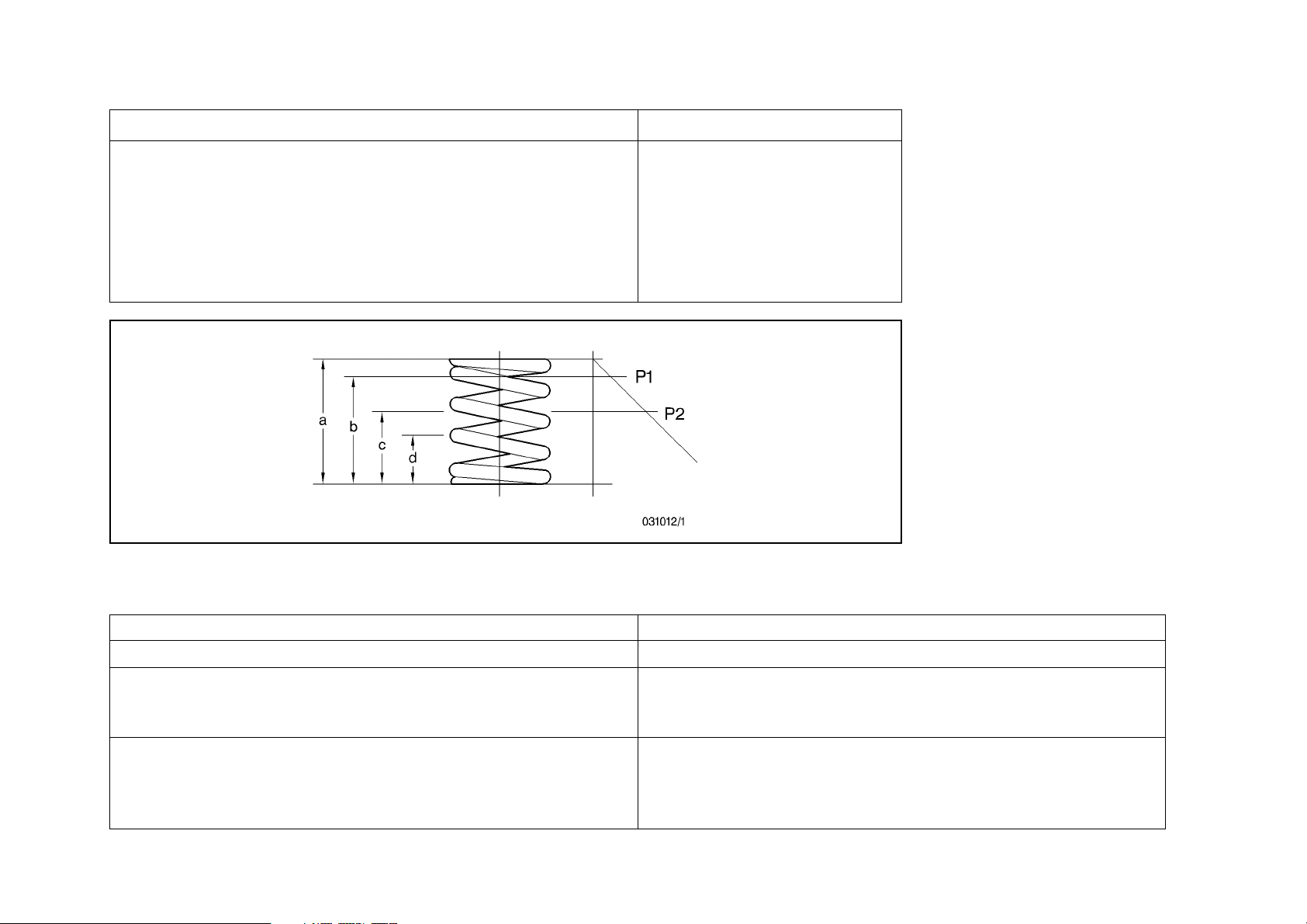
External spring
Workshop manual - Diablo 6.0
Free length (a)
With valve closed (b)
With valve open (c)
Compressed (d)
Load (with closed valve) P1
Load (with open valve) P2
Number of active coils
Fig. 12/1 - Valve springs
Engine lubrication
38.9
20.9
245.25
549.36
3.81
31
22
± 3.92 N
± 9.81 N
Circuit Forced lubrication with radiator and thermostatic valve
Radiator oil Single, separated
Pressure in circuit with hot engine (90°C)
– at 1000 RPM
– at 6000 RPM
Thermostatic valve
– start
– 9 mm
– max. stroke
10-20
1.5 – 2.5 [bar]
5 – 7 [bar]
80 °C
95 °C
11
Page 30

Workshop manual - Diablo 6.0
Engine cooling
Circuit Forced circulation with thermostatic control
Radiators Two with fan
Fans
– on
80 °C
74 °C
– off
Circuit pressure with hot engine (max.) 1.2 [bar]
Thermostatic valve
– start
– 7 mm
– Max. stroke (at 95 °C)
80 °C
86 °C
11
10-21
Page 31

Workshop manual - Diablo 6.0
REMOVAL AND REFIT
This operation requires a car lift and a hoist with a rocking lever and 4 chains to sling the engine, to be fixed on the exhaust manifold hooks.
0310013
Fig. 13 – Engine–gearbox removal
List of operations to be carried out before the removal of the engine:
• disconnect the positive and negative wires from the battery
• disconnect the engine cooling hoses, oil system hoses, fuel system hoses and air conditioning hoses from their relevant radiators and accessories
10-22
Page 32

Workshop manual - Diablo 6.0
• disconnect the engine injection wiring from the general wiring and all the secondary electric connectors, the earth cables and
the starter motor wires
• disconnect the oil delivery hose from the clutch cylinder located on the clutch bell
• remove the gear knob and switch on the tunnel in the passenger compartment
• lift the car and working from underneath, remove the gearbox support; loosen the two engine supports on the sides of the
crankcase
• remove the catalysts and harness the engine as described above
• remove the engine supports and, after checking all the hoses and wirings are disconnected, remove the engine-gearbox group.
ASSEMBLY
Every time the engine is disassembled clean the crankcase, especially the lubrication ducts.
Replace all oil seals and gaskets.
After the crankcase has been carefully cleaned, assemble the liners as follows:
• fit the rings to the liners;
• insert the liners one after the other in the crankcase;
• check that liners protrusion from the crankcase is in accordance with the values prescribed. Make this check using the liner
holder tools (No. 961195027) tightened to the specified torque on the cylinder head bolts. Do not remove the tools before the
heads are assembled;
• assemble the main bearings on the engine block;
• fix the crankshaft to the engine block using special supports No. 961495014;
Special supports No. 961495014 must be installed with the main bearings between support and shaft.
• before fitting the piston rings on the pistons, check that the end clearance is within the prescribed value;
To make this check, fit the piston rings on the liner. When fitting the piston rings make sure that the caption ”TOP” is
facing upwards.
• before assembling the piston-conrod group in the cylinder liner, lubricate the piston rings and the liner with engine oil. Position
the piston ring notches so that they are displaced by about 120° and ensure that no notch coincides with the direction of the piston pin axis;
10-23
Page 33

Workshop manual - Diablo 6.0
• assemble the conrod-piston group to each cylinder;
When performing this operation turn the crankshaft in the direction of its rotation.
The grooves on the conrod big end must face the crank arms when assembling the conrod-piston group.
• tighten the connecting rod big ends following this procedure:
- clean the threads very carefully;
- lubricate the bolt under the big end and the thread;
- tighten the bolts following the specified procedure (see Section 02 – DRIVING TORQUES);
• before assembling the lower crankshaft support smear LOCTITE 518 paste on the contact surface;
• fit the main bearings on the lower support;
• tighten the lower support to the prescribed torque following the specified procedure (see Section 02 – DRIVING TORQUES);
• assemble the timing components on the front part of the crankcase; assemble the oil pump on the timing cover;
• place cylinder No.1 at T.D.C. using a dial gauge;
• it the pre-assembled cylinder heads taking care that the camshaft positions coincide with the reference marks on the supports;
Cool the guides and valve seats (about -190°) before assembling onto the head. Pre heat the head to about 190°.
• before tightening the heads lubricate the upper surface of the washers, nuts and bolt threads with Molycote 1000 paste;
• tighten the head bolts following the prescribed procedure (see Section 02 – DRIVING TORQUES) using wrench No. 9008019;
• proceed with engine timing;
• before assembling the oil sump smear the contact surface with LOCTITE 518.
10-24
Page 34

Workshop manual - Diablo 6.0
CHECKS AND ADJUSTMENTS
Valve clearance
Intake 0.35 [mm]
Exhaust 0.50 [mm]
Replace the spacer rings until the clearance required is found. Use tool No. 961195014 to remove and replace the spacer rings.
When the cylinder heads are removed it is advisable to use tool No. 961195004 for the intake valve and No. 961195003 for the
exhaust valve.
Position the spacer rings (pads) with the side indicating the thickness facing the tappet.
Check the valve clearance when the engine is cold.
031015
031014
Fig. 14 – Valve clearance check Fig. 15 – Spacer ring replacement
10-25
Page 35

Workshop manual - Diablo 6.0
Locking the phase variator
A phase variator is installed in the engine on the intake timing shafts.
If this is removed, or when setting up the timing system, make sure that the slots on the moving part are correctly positioned in
relation to the fixed part securing holes.
Position check
• visually check that the slot is centred to the hole (part A)
• if it is not (position B), proceed with the positioning.
Positioning
• take out the moving part (2) from the fixed part (1); find a new angle position of the moving part, making attempts by re-inserting it fully with a rotating movement and checking the position of the slots in relation to the holes (position A);
• when the correct position is found secure the moving part by inserting ring (4) and tightening the screws to the prescribed
torque.
031018/1
Fig. 16 – Locking the phase variator
1 Variator body
2 Fixed part
3 Moving part
4 Spacer ring
A: Correct position
B: Incorrect position
10-26
Page 36

Workshop manual - Diablo 6.0
Timing regulation
Intake Exhaust
Start before TDC [°] 40 –––
End after BDC [°] 68 –––
Start before BDC [°] ––– 68
End after TDC [°] ––– 22
Lift during overlap stage [mm]
• New timing chain (less than 6 hours)
• Adjusted timing chain (more than 6 hours)
Adjustment
To adjust proceed as follows:
• rotate the crankshaft until the dial gauge shows that piston No. 1 coincides with the ignition TDC (use dial gauge holder No.
961195025);
• fit the setting dial and lever No. 961495012 to rotate the crankshaft;
• fix the reference point on the crankcase and goniometer for the TDC;
1.15
1.00
± 0.05
± 0.05
0.20
0.35
± 0.05
± 0.05
10-27
Page 37

Workshop manual - Diablo 6.0
Fig. 17 – Checking TDC in cylinder No. 1
1 Tool No. 961495012
2 Tool No. 961195025
031016
10-28
Page 38

Workshop manual - Diablo 6.0
Exhaust:
• fit sprocket holder tool No. 961195042 to fix the gears on the camshafts;
• check that the reference marks (A) on the supports and the camshafts coincide;
• fix the centring dowel on the cams using the tool;
Intake:
• loosen the six variator screws;
• check that the reference marks (A) on the supports and the camshafts coincide;
• tighten the six variator screws without locking;
• make one turn (in the engine rotation direction) to recover the chain slack;
• check the reference marks (A) again on the supports and the camshafts and if necessary reposition the shafts;
• position holder No. 961195026 with the dial gauge to measure the valve lift on cylinder No. 6;
Exhaust:
• place the dial gauge on the exhaust valve tappet and check that the lift is that specified;
• if it is not, remove the centring dowel using tool No. 9611195024 and turn the exhaust side camshaft with a 26 mm wrench until
the correct exhaust valve lift of cylinder No. 6 is found (the position is at TDC overlap);
1 Tool No.
031017 031018
961495026
Fig. 18 – Reference marks Fig. 19 – Checking and adjustment of lifts
10-29
Page 39

Workshop manual - Diablo 6.0
• fit the centring dowel on the cams using the tool;
Intake:
• loosen the six variator screws;
• turn the intake side camshaft with a 26 mm wrench until the correct intake valve lift of cylinder No. 6 is found (the position is at
TDC overlap);
To obtain the prescribed values at the end of the operations it is necessary to double the adjusting values of the lifts to
be applied.
• tighten the six variator screws to the prescribed torque;
• repeat the whole procedure for the right-hand cylinder bank, bringing cylinder 7 to ignition TDC (60° after ignition TDC of cylinder 1) and measure the lifts on cylinder 12.
Checking
To check, proceed as follows:
• rotate the crankshaft until the dial gauge shows that piston No. 1 coincides with the ignition TDC (use dial gauge holder No.
961195025);
• fit the setting dial and lever No. 961495012 to rotate the crankshaft;
• fix the reference point on the crankcase and goniometer for the TDC;
• position holder No. 961195026 with the dial gauge to measure the valve lift on cylinder No. 6;
• place the dial gauge on the intake tappet and check the lift is that specified;
• place the dial gauge on the exhaust valve tappet and repeat the procedure;
• repeat the whole procedure for the right-hand cylinder bank, bringing cylinder 7 to ignition TDC (60° after ignition TDC of cylinder 1) and measure the lifts on cylinder 12.
• make the necessary adjustment if these conditions are not found.
Locking check on phonic wheel for engine timing sensor
Proceed as follows:
• remove the cover of the phonic wheel on the camshaft, then rotate it in the direction of engine rotation to bring the tooth near
to cylinder bank 1-6 sensor using the starter motor;
• move the sensor tooth along the last section engaging the 5th gear and moving the vehicle in the travel direction;
10-30
Page 40

Workshop manual - Diablo 6.0
• lift the vehicle and with a large screwdriver turn the camshaft to bring the reference notch 30° in advance of the flywheel to
correspond with the reference on the engine block (two holes not in line);
Do not reverse the direction of engine rotation to avoid errors caused by backlash: if you go beyond the point, make two
complete engine rotations then repeat the procedure.
The 30° do not represent the ignition advance, but only an assembly reference.
• check that the tooth is perfectly centred to the sensor;
• if it is not, loosen the screw and direct the phonic wheel until centring is obtained;
• check that the distance between the tooth and the sensor (gap) is between 0.7 and 1 mm. If necessary shim the sensor.
10-31
Page 41

Workshop manual - Diablo 6.0
Fig. 20 – Timing sensor-phonic wheel locking references
1 Speed sensor and TDC
2 Engine flywheel
3 Mechanical TDC reference
4 30° advance reference
5 Timing sensor cylinder bank 1-6
6 Timing sensor cylinder bank 7-12
7 Phonic wheel
A Crankshaft
B Camshaft
131022
10-32
Page 42

COOLING CIRCUIT
Workshop manual - Diablo 6.0
Fig. 21 – Cooling circuit
1 Water pump
2 Thermostatic body
3 Radiator
4 Electric fan
5 Expansion reservoir
6 Gauge temperature sensor
7 Engine control system temperature sensors
8 Self-drain pipe
9 Climate control unit
131023
10-33
Page 43

Description
Closed loop cooling system with forced circulation by centrifugal pump belt-driven by the crankshaft.
Main components:
• two radiators
• two electric fans
• thermostatic valve in thermostat body
• centrifugal pump
• sensor for temperature gauge
• pipes for self-drain system
Workshop manual - Diablo 6.0
Fig. 22 – Water pump and thermostat
1 Coolant temperature sensor
2 Coolant temperature sensor
3 Thermostat
4 Thermostat cover
5 Pump impeller
6 Front seal
7 Shaft
131024
8 O-ring
9 Pump casing
10 Belt
11 Pulley
12 Belt tensioner assembly
13 Coolant temperature sensor
10-34
Page 44

Workshop manual - Diablo 6.0
Radiators and electric fans
The radiators are fitted with a tap in the lower part to drain off the water, and two caps in the upper part to bleed off the air.
The engine control unit governs the switching on of the electric fans according to the coolant temperature and when the air conditioning system is activated.
Since the coolant temperature is read by the relevant sensor the thermal contact is no longer installed on the radiator.
Thermostatic valve
The thermostatic valve is located in the thermostat body.
Expansion reservoir
The expansion reservoir compensates the coolant volume variations caused by engine heating.
The reservoir cap is fitted with a gauged valve that controls the system maximum pressure.
Always fill and top up the cooling system through the expansion reservoir filler.
Radiator removal
To remove the radiators proceed as follows:
• take off the exhaust system and the catalytic converters;
• remove the left and right wheel housings;
• remove the water sleeves;
• unscrew the radiator fixing bolts;
• take off the radiators from the side towards the car centre.
Filling up the system
• fill up the system through the expansion reservoir;
• remove the expansion reservoir cap;
• check the level in the expansion reservoir during heating;
• heat the engine to operating temperature to allow the thermostat valve to open;
• select HI C/F on the digital display of the air conditioner so that the heating radiator liquid starts to circulate;
• top up the expansion reservoir;
• as soon as the fans start, fit on the expansion reservoir cap;
• check the level again when the engine is cold.
10-35
Page 45

Workshop manual - Diablo 6.0
LUBRICATION CIRCUIT
Description
Force feed lubrication system with gear pump with oil vapours re-cycling. Oil cooling system with thermostatic valve.
Main components
• oil pump with internal gears and pressure regulator valve;
• thermostatic valve in thermostat body-filter seat
• radiator;
• cartridge filter;
• pressure sender;
• temperature sender;
Fig. 23 - External circuit
10-36
031025
1 Oil pressure sensor
2 Thermostatic valve body
and filter seat
3 Oil return pipe
4 Oil delivery pipe
5 Oil radiator
6 Oil filter
Page 46

Workshop manual - Diablo 6.0
Thermostatic valve
The lubrication system is equipped with a thermostatic valve that according to the oil temperature allows the oil passage through
the heat exchanger. The thermostatic valve is located on the thermostatic body/filter seat.
The main checking data is:
Temperature (°C) Stroke
80 start
95 9 mm
Max. stroke 11 mm
Fig. 24 - Thermostatic valve
1 From oil pump : 1a – To oil
radiator; 1b – From oil
radiator
2 To filter
3 To engine
A Valve open, oil path 1-1a-
1b-2-3
B Valve closed, oil path: 1-
2-3
031026
10-37
Page 47

Oil pump check
• check the pump body and cover, replace the parts if there are scorings;
• clean suction and delivery carefully with a petroleum jet and compressed air;
• check the driving and driven gears; if they are in bad condition or worn replace them;
• check clearances;
• check that the relief valve piston moves properly in its seat;
• check the bearing.
Workshop manual - Diablo 6.0
Fig. 25 - Oil pump
10-38
181027
1 Crankshaft
2 Coupling
3 Pump body
4 Driven gear
5 Driving gear
6 Timing system cover
7 Pressure regulator
8 Pulley
9 Oil seal
Page 48

Workshop manual - Diablo 6.0
Check conditions of calibrated hole (arrow) and clean if required.
Level check and oil replacement
Check the oil level with the dipstick every 500 km, preferably with the engine cold. If the engine is hot, wait a few minutes to allow
the oil to flow back to the sump.
Replace the oil when the engine is hot, draining it through the drain hole (A) in the bottom of the sump.
To have access to the engine oil filter remove the panel in the bottom of the car.
• remove the oil filter and replace it with a new one, after lubricating the seal with engine oil.
• fit the filter and tighten by hand.
031028
Fig. 26 – Engine oil drainage cap Fig. 27 – Engine oil filter
10-39
181029
Page 49

PNEUMATIC UTILITY CONNECTIONS
(EEC versions only)
Workshop manual - Diablo 6.0
Fig. 28 - Pneumatic utility connections
1 Vacuum reservoir
2 Intake manifold block 7-12
3 ENCS system solenoid valve
4 ENCS system actuators
181030
10-40
Page 50

15 – ENGINE CONTROL SYSTEM
Workshop manual - Diablo 6.0
15-1
Page 51

CONTENTS
Workshop manual - Diablo 6.0
DESCRIPTION P. 3
SYSTEM MANAGEMENT STRATEGIES P. 4
Operating principle
Signal frame management
EEC engine control system functional layout
USA engine control system functional layout
Injection system
Activated carbon filter washing
Ignition system
Engine idle speed control
ELECTRICAL/ELECTRONIC SYSTEM P. 17
Engine speed and TDC sensor
Engine timing sensor
Absolute pressure sensor
Lambda sensor
Ignition coil
Spark plugs
Engine coolant temperature sensor
Intake air temperature sensor
GFA control unit
FUEL SUPPLY SYSTEM P. 25
Fuel pump
Fuel filter
Fuel manifold
Fuel pressure regulator
Injectors
INTAKE SYSTEM P. 31
Throttle opening actuator
Throttle case
Throttle position sensor
EXHAUST SYSTEM P. 35
Catalytic converter
Exhaust gas temperature control device
Exhaust noise control system ENCS
ANTI-EVAPORATION DEVICES P. 40
Recycling system for gas coming from the crankcase (blow-by)
Fuel anti-evaporation system
CHECKS AND ADJUSTMENTS P. 44
General overview
Basic adjustment of idle speed
Idle speed adjustment
CO and HC contents check
Idle mixture strength (Arabia version)
Fuel circuit checks
SELF-DIAGNOSTICS SYSTEM P. 50
General overview
OBD II self diagnostics system
SYSTEM DIAGNOSTICS P. 53
Preliminary checks
OBDII scan tool
LDAS (Lamborghini Data Acquisition System)
OBDII strategy error codes
15-2
Page 52

Workshop manual - Diablo 6.0
DESCRIPTION
The LIE system is a system that integrates a digital electronic ignition spark advance and static timing system with an electronic
indirect fuel injection system of the multiple timed sequential type.
According to the structure of the engine, which has the cylinders divided into two cylinder banks, two complete systems have been
applied that are opportunely synchronised with each other, and each controls a cylinder bank of six cylinders. As a consequence
there are two engine control units, connected to each other by the CAN line, managing the injection and ignition of each cylinder
bank. These control units are also connected by the CAN line to the GFA control unit that co-ordinates and manages many functions, especially concerning diagnostics.
The system can be divided into the following sub-systems:
ELECTRICAL/ELECTRONIC SYSTEM
FUEL SUPPLY SYSTEM
INTAKE SYSTEM
EXHAUST SYSTEM
ANTI-EVAPORATION DEVICES
The system can acquire the following parameters:
• engine rpm;
• correct TDC sequence of the cylinders (injection timing);
• absolute pressure in the intake manifold;
• throttles position and position variation;
• intake air temperature;
• engine coolant temperature;
• exhaust gas internal temperature;
• mixture titration ;
• battery voltage;
• start-up of air conditioner;
• exhaust manifold pressure;
• fuel anti-evaporation circuit pressure.
This information if analogue, is converted to digital signals by the A/D converters so that it can be used by the control unit.
15-3
Page 53

Workshop manual - Diablo 6.0
A software management program is installed in the control unit memory which contains several strategies, each of which manages
a certain system control function.
Using the information (input) listed above, each strategy processes a series of parameters based on the data maps stored in special areas of the control unit, then controls the system actuators (output) (the devices that permit the engine to operate).
All the system components can operate on both cylinder banks. Furthermore all the connectors are marked with a
coloured band:
cylinder bank 1-6 : white;
cylinder bank 7-12: yellow.
For further information on the LIE and GFA control unit layouts, the pin-outs and electrical connections, see the Electric
Wiring Diagrams Manual.
SYSTEM MANAGEMENT STRATEGIES
Operating principle
Any operating point of the engine is found by two parameters:
• rotation speed;
• engine load.
Having found these parameters through the relevant processing, it is possible to calculate and obtain the injection (quantity of fuel
delivered and relevant timing in relation to bursting TDC), ignition (correct spark advance) and any other function for each engine
operating point.
In the LIE system the rotation speed is measured directly through the relevant sensor, whereas the engine load is determined indirectly, through a “density” parameter (representing the engine load) according to the absolute pressure in the intake manifold and
the temperature of the intake air.
When testing the engine – and afterwards the car – specific maps are prepared in which, for a certain number of speed-load parameter pairs, the time/injection timing values and ignition spark advance required for correct engine operation are stored.
These injection time values are further corrected according to the signal coming from the lambda sensor that, based on certain
operation strategies, determines a continuous fluctuation of the mixture titration around a stoichiometric value.
The system is therefore defined as “speed-density-lambda” type since the injection time is fundamentally determined by these
three parameters.
15-4
Page 54

Workshop manual - Diablo 6.0
All operation situations that require special adaptation of the calculated time/injection timing values, spark advance and boosting
pressure are managed by the engine control unit, correcting the calculated base values through suitable strategies according to
the signals coming from the system sensors.
Signal frame management
The name “signal frame” implies the group of signals coming from the sensor on the crankshaft and the sensor on the
camshaft which, since they each have a well-defined reciprocal position send to the control unit a synchronised
sequence of signals that the control unit is able to acknowledge.
Upon ignition, the control unit acknowledges the injection and ignition timing, which are fundamental for the subsequent operation
of all the strategies.
This acknowledgement takes place on the basis of the interpretation of the sequence of signals coming from the engine speed sensor (one which serves both systems), on the engine flywheel and from the engine timing sensor on the camshaft.
On the engine flywheel there is a phonic wheel with six equidistant teeth: the angle between two consecutive teeth is therefore
60°. The phonic wheel is locked so that the teeth reach the sensor with an advance of 10° in relation to the relevant bursting TDC
(electric dead centre advanced by 10° in relation to the mechanical dead centre)
A cam is locked on the camshaft of the 7-12 cylinder bank that generates a signal for each of the two sensors. The two sensors are
shifted by 30°, corresponding to the opening 60° of the two engine cylinder banks.
The signal is sinusoidal and has to be converted to a digital signal by the A/D converter inside the control unit.
The cylinder sequence obviously depends on the engine bursting order which is:
1 – 7 – 4 – 10 – 2 – 8 – 6 – 12 – 3 – 9 – 5 – 11.
15-5
Page 55

Fig. 1 - Signal panel (crankshaft degrees)
SMOT: engine speed and TDC sensor signal
SCAM 1-6: cylinder bank 1-6 timing sensor signal
SCAM 7-12: cylinder bank 7-12 timing sensor signal
Workshop manual - Diablo 6.0
031501
15-6
Page 56

Workshop manual - Diablo 6.0
Fig. 2 - EEC engine control system function layout
181502
15-7
Page 57

Key
EEC engine control system function layout
Workshop manual - Diablo 6.0
1 Engine control ECU
2 Throttle position actuator ECU
3 Engine rpm and TDC sensor
4 Injectors block 1-6
5 Single ignition coil
6 Roll-over valve
7 Fuel pump
8 Fuel vapour pressure sensor
9 Absolute pressure sensor block 7-12
10 Exhaust gas pressure sensor
11 Air temperature sensor
12 Catalyser lambda sensor block 1-6
13 ENCS solenoid valve
14 Radiator fans
15 Throttle casing block 7-12
16 Throttle position sensor (single)
17 Timing variator solenoid valve block 1-6
18 Catalyser block 1-6
19 ENCS valve
20 Pressure regulator block 1-6
21 Coolant temperature sensors
22 Catalyser block 7-12
23 Pressure regulator block 7-12
24 Throttle casing block 1-6
25 Engine timing sensor
26 Catalyser lambda sensor block 7-12
27 Absolute pressure sensor block 1-6
28 Battery
29 Carbon canister washout solenoid valve
30 Carbon canister
31 Rear relay and fuse box
32 Injectors block 7-12
33 Throttle opening actuator
34 GFA ECU
35 Instrument connection
36 Ignition switch
37 Climate control system connection
38 Front relay and fuse box
15-8
Page 58

Workshop manual - Diablo 6.0
Fig. 3 - USA engine control system function layout
181503
15-9
Page 59

Key
USA engine control system function layout
Workshop manual - Diablo 6.0
1 Engine control ECU
2 Throttle position actuator ECU
3 Engine rpm and TDC sensor
4 Injectors block 1-6
5 Single ignition coil
6 Roll-over valve
7 Fuel pump
8 Fuel vapour pressure sensor
9 Absolute pressure sensor block 7-12
10 Floating valve
11 Exhaust gas pressure sensor
12 Air temperature sensor
13 Pre-catalyser upstream lambda sensor block 1-6
14 Pre-catalyser block 1-6
15 ENCS solenoid valve
16 Thermocouple control unit
17 Pre-catalyser thermocouple
18 Pre-catalyser downstream lambda sensor block 1-6
19 Radiator fans
20 Throttle casing block 7-12
21 Throttle position sensor (single)
22 Timing variator solenoid valve block 1-6
23 Catalyser block 1-6
24 ENCS valve
25 Pressure regulator block 1-6
26 Coolant temperature sensors
27 Catalyser block 7-12
28 Pressure regulator block 7-12
29 Throttle casing block 1-6
30 Pre-catalyser downstream lambda sensor block 7-12
31 Engine timing sensor
32 Pre-catalyser block 7-12 (USA)
33 Pre-catalyser upstream lambda sensor block 7-12
34 Absolute pressure sensor block 1-6
35 Battery
36 Carbon canister washout solenoid valve
37 Carbon canister
38 Rear relay and fuse box
39 Injectors block 7-12
40 Throttle opening actuator
41 GFA ECU
42 Instrument connection
43 Ignition switch
44 Climate control system connection
45 Front relay and fuse box
15-10
Page 60

Workshop manual - Diablo 6.0
Injection system
The aim of the injection management strategies is to supply the engine with the correct quantity of fuel at the required moment
according to the engine operating conditions.
The injection management is essentially the calculation of the injection time, the determination of the injection timing and the subsequent actuation through the injector command.
The “basic” injection time is calculated by a mathematical interpolation of the speed-load map: the values contained in the map,
obtained experimentally, also depend on the injector specifications.
The “final” injection time is obtained by a calculation algorithm in which the “basic” time is corrected by coefficients that take into
account the different engine operating conditions, which are indicated by the various sensors installed in the system.
Mixture titration check
(check in feedback, closed loop)
This strategy corrects the injection times so that the mixture titration fluctuates continually.
The frequency of the fluctuation changes according to the engine load and speed: it ranges in tens of Hertz.
The ratio below is the mixture ratio and is indicated with the Greek letter
α (alpha):
quantity of air taken in by the engine
quantity of fuel injected
α
The ratio below is the stoichiometric mixture ratio and is indicated with
st
:
theoretical quantity of air to
burn all the injected fuel
quantity of injected fuel
The ratio below is the mixture titration and is indicated with the Greek letter
λ (lambda):
quantity of air taken in by the engine
theoretical quantity of air to burn
all the injected fuel
The stoichiometric ratio depends on the type of fuel: for current unleaded petrol it is equivalent to approx. 14.7, that corresponds
to a lambda titration = 1.
A “rich” mixture is when the quantity of air is less than the stoichiometric quantity and in this case we have lambda <1;
A “weak” mixture is when the quantity of air is greater than the stoichiometric quantity and in this case we have lambda >1.
15-11
Page 61

Workshop manual - Diablo 6.0
The feedback operation (closed loop) permits the catalytic converters to operate efficiently. This operating condition also enables
the engine control unit to run its self-learning function.
Cold start and running
The injection time during the starter motor actuation is determined by a special mapping according to the coolant temperature:
after ignition has taken place the system passes over to the standard speed-load mapping.
When there is a cold start, since there is a natural impoverishment of the mixture due to reduced evaporation and heavy condensation on the inner walls of the fuel intake manifold, the “basic” injection time is increased by a multiplying coefficient according to
the engine temperature.
Full load
The strategy is enabled when the throttle exceeds a certain threshold. The “basic” injection time is increased by a multiplying coefficient according to the engine speed.
Acceleration and deceleration
Acceleration and deceleration are interpreted by the system as transient stages between two stationary conditions: this may be
positive (acceleration) or negative (deceleration).
The transient strategy is very complicated since many factors have to be taken into consideration.
Usually the injection time is increased for positive transients and decreased for negative transients.
The size of the correction depends basically on the engine load variation: however also values such as throttle movement speed,
engine speed, engine temperature (coolant and intake air) are also involved.
Injectors control
The injectors control is a timed sequential type.
Rpm limiting
The strategy limits the peak speed that can be reached by enabling the cut-off when the engine reaches this speed.
Peak rpm = 7800 rpm
15-12
Page 62

Workshop manual - Diablo 6.0
Fuel pump control
Each of the fuel pumps is controlled by the engine control unit through a single relay.
The pump is stopped:
• if the engine speed goes down to less than 250 rpm approx.;
• after a certain time (about 3 seconds) with the key on MAR without starting up (timed enable)
Self learning
The control unit has a self-learning function that memorises any deviation between basic mapping and corrections set by the
lambda sensor that persists during operation, within certain load and speed limits. These deviations (due to production tolerances
and ageing of system and engine components) are permanently stored, enabling adaptation of the system operation upon progressive engine and component alterations compared to the original condition.
The self-learning strategy uses the signals coming from the lambda sensor to continually update a specific mapping
contained in a special area of the memory, which contains the correction values to perform during the calculation of
the final injection time.
If a control unit is replaced a road test is necessary to allow the engine to reach its temperature and so that the strategy can perform its self-learning.
Activated carbon filter washing
This strategy checks the position of the activated carbon filter washing solenoid valve in this way:
• with the engine hot the control unit controls the solenoid valve so as to check the quantity of fuel vapours sent to the intake
(activated carbon filter washing), according to the engine speed and load. The system alternates washing periods with no
washing periods: during the latter the self-adaptation strategy can be enabled under these conditions:
• during start-up the solenoid valve remains closed, preventing the fuel vapours from enriching the mixture;
• after a cold start the solenoid valve remains closed during the entire engine warming up.
15-13
Page 63

Workshop manual - Diablo 6.0
Ignition system
The ignition control mainly consists of determining the spark advance required according to the engine operating conditions and
its actuation by the piloting of the power transistor incorporated in the power module inside the engine control unit.
The spark advance calculated on the basis of the engine load and speed is then corrected according to different engine operating
conditions.
Each coil primary is supplied by the battery voltage through a relay which, in its turn is controlled by the engine control unit: the
earth connection is through the power transistor.
The engine control unit, after a cylinder TDC signal, sends a signal, with a certain delay, to the relevant power module, that starts
at that moment (conduction start moment) to send current to the coil primary circuit to bring the value to about 6 Amperes (saturation current).
Obviously this moment varies in angle in relation to the bursting TDC of each cylinder since the dwell needed to saturate the current in the coil primary circuit is constant, whereas the time required by the engine to make two revolutions (cycle) reduces as the
rpm increases.
The engine control unit signal remains until the moment of the desired spark advance on the specific cylinder.
The moment the control unit removes the signal to the power module, the current in the coil primary circuit is cut off. This, by
induction, generates a sudden rise in voltage on the secondary circuit that is discharged to earth, generating a spark on the ignition spark plug.
Each cylinder has a coil fitted directly onto the spark plug without a high voltage cable.
The coils are operated when the engine is started in advance by a few cycles with respect to ignition. In a similar way,
the coils are operated for a few additional cycles after the engine has been stopped.
15-14
Page 64
Workshop manual - Diablo 6.0
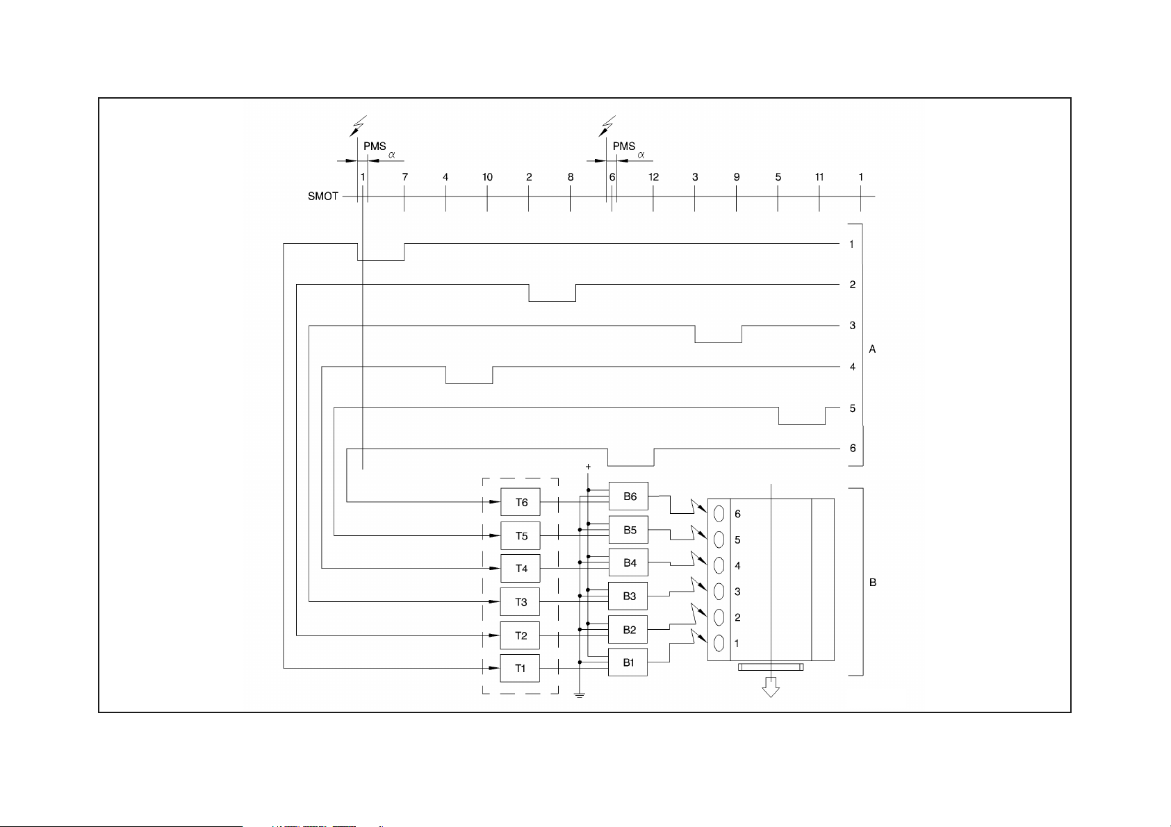
Fig. 4 - Ignition system functional layout (cylinder bank 1-6)
131504
15-15
Page 65

Workshop manual - Diablo 6.0
SMOT: crankshaft sensor/signal
a: spark advance
A cylinder bank 1-6 modules commands
B cylinder bank 1-6 connection diagram
B1/../B6: cylinder bank 1-6 coils
T1/../T6: cylinder bank 1-6 power transistors
Firing
order: 1-4-2-6-3-5
The cylinder bank 7-12 commands are delayed by 60° of crankshaft in relation to cylinder bank 1-6 commands shown in
the figure.
Engine idle speed control
The target is to hold the engine speed around the stored value, in its turn a reverse function of the coolant temperature, suitably
changing the position of the throttle (cold engine) or the spark advance (hot engine).
• Start up and cold engine
When the key is inserted, the throttle opening actuator opens the throttle of each throttle case by an amount that depends on
the engine temperature, so as to ensure the amount of air needed to hold the set speed, according to the engine temperature.
While heating, the actuator modulates the throttle position – and consequently the engine speed – until they close completely at
an engine temperature of about 70 °C.
• Hot engine
When the key is inserted, the throttle opening actuator opens the throttle of each throttle case sufficiently to ensure the quantity of air needed for a hot start-up.
The engine idle speed is held steady close to the set value changing the spark advance so as to offset any speed fluctuations.
15-16
Page 66

Workshop manual - Diablo 6.0
ELECTRICAL/ELECTRONIC SYSTEM
Engine speed and TDC sensor
The sensor is fixed to the crankcase, engine flywheel side.
Operation principle
The sensor (fig. 5) consists of a tubular casing (1) inside which there is a permanent magnet (3) and an electrical winding (2).
The magnetic flow created by the magnet (3) due to the passing of the phonic wheel teeth, fluctuates according to the gap variation.
These fluctuations induce an electromotive force in the coil (2) at the ends of which alternate a positive voltage (tooth facing sensor) and a negative voltage (gap facing the sensor). The peak value of the output voltage depends, other factors remaining unaltered, on the distance between the sensor and the tooth (air gap).
Air gap: 0.75
The phonic wheel is locked so that the teeth arrive to the sensor with an advance of 10° in relation to the relevant bursting TDC
(Fig. 6).
No adjustment can be made to the sensor angle position.
÷ 0.90 [mm]
15-17
Page 67

031505 031506
Fig. 5 - Speed and TDC sensor Fig. 6 - Assembly diagram
Workshop manual - Diablo 6.0
1 Sensor
2 Engine flywheel
3 Tooth
4 Reference on
cup
Engine timing sensor
The timing sensors are installed on the end of the exhaust camshaft of the 7-12 cylinder bank. They are shifted by 30°, corresponding to the 60° of the two engine cylinder banks.
Operating principle
The operation is exactly the same as described for the speed and TDC sensor.
15-18
Page 68

Workshop manual - Diablo 6.0
Absolute pressure sensor
The absolute pressure sensors are at the sides of the engine near the ignition coils of the respective cylinder banks.
Operating principle
The sensitive element, enclosed in a plastic container, consists of a Wheatstone bridge stencilled on a very thin ceramic plate
(diaphragm) installed on the lower part of an annular support.
The diaphragm separates two chambers: in the lower chamber, which is sealed, a vacuum has been created, whereas the upper
chamber is in direct communication through piping with the measuring point.
When operating, the pressure that generates on the measuring point produces a mechanical action on the sensor diaphragm which
deflects, thus varying the resistor values.
Since the power supply is constant (+5 V) the resistor variation causes an output voltage variation (V) which is proportional to the
pressure value.
1 Pulse generator
eccentric
2 Cylinder bank
1-6 sensor
3 Cylinder bank
7-12 sensor
131507 031508
Fig. 7 - Timing sensor Fig. 8 - Absolute pressure sensor
15-19
Page 69

Workshop manual - Diablo 6.0
Lambda sensor
This is a sensor that generates an electric signal directly bound to the ratio between the oxygen in the exhaust gas and the oxygen
in the outside air. Through this it is possible to find the deviation from the correct stoichiometric ratio of the air-fuel mixture sent
to the cylinders.
Each cylinder bank has its own oxygen sensor installed on the exhaust gas inlet coupling in the catalytic converter of the exhaust
system.
The lambda sensor is connected to the outside air by special holes, and in any case there is no connection between the
exhaust gas and the air.
1 Contact
2 Ceramic support
3 Sensor ceramic
4 Protective pipe
5 Electric cable
6 Spring
7 External casing
8 Metal frame
9 Electrode
10 Electrode
031509
Fig. 9 - Heated lambda sensor and characteristic curve
Once the operating temperature has been reached (between approx. 350 and 800°C) the generated electric signal fluctuates continually between 0 and 800 mV. In the case of weak mixture with too much oxygen in the exhaust gas, the output signal is low, less
than 100 mV; if instead the mixture is rich – low oxygen content in the exhaust gas, the signal is high, over 800 mV.
To start its operation sooner, and to avoid the danger of splattering if the engine runs for a long time at idle speed, the lambda sensor is heated not only by the exhaust gas, but also by an electric resistor.
15-20
Page 70

Workshop manual - Diablo 6.0
Ignition coil
The ignition circuit is static type with inductive discharge; the high voltage is provided by six pencil coils fitted directly onto the
cylinder head for each block.
The coils have a magnetic closed circuit with the windings in a plastic container immersed in epoxy resin. Each coil is directly connected to the spark plug without high voltage cables.
1 Ignition switch
2 Battery
3 Power supply relay
4 Pencil coil
5 Spark plug
6 Engine control unit
131510
Fig. 10 - Pencil ignition coil
The coil primary circuit is supplied by relay, controlled by the engine control unit after it has acknowledged the rating signal
coming from the relevant sensor (thus with engine rotating driven by the starter motor).
15-21
Page 71

Workshop manual - Diablo 6.0
Spark plugs
It is most important to use spark plugs with a thermal degree and specifications that correspond to the standards. If another type
of spark plug is used for replacement it must be verified that it has the same specifications as the original ones.
Engine coolant temperature sensor
The sensor is installed on the thermostat.
It has a brass body that protects the actual resistive element, which consists of an NTC thermistor (Negative Temperature Coefficient) in which electrical resistance decreases as there is an increase in temperature and of the relevant connector.
Operating principle
The reference voltage is 5 Volts: since the control unit input circuit has been designed as a voltage divider, the reference voltage is
divided between a resistor in the control unit and the sensor itself.
As a result the control unit is able to assess the resistance variations of the sensor through the voltage changes, thus receiving
information on the temperature.
Intake air temperature sensor
The sensor is installed on the intake manifold.
It has a synthetic material cage that protects the actual resistive element, which consists of an NTC thermistor (Negative Temperature Coefficient) in which electrical resistance decreases as there is an increase in temperature and of the relevant body with connector.
Operating principle
The operation is exactly the same as described for the coolant temperature sensor.
15-22
Page 72

Workshop manual - Diablo 6.0
031511
Fig. 11 - Spark plugs electrode gap Fig. 12 - NTC type sensor characteristic curve
031512
15-23
Page 73

Workshop manual - Diablo 6.0
GFA control unit
The GFA control unit (Auxiliary Functions Management) is an on board computer that governs the operation of many devices.
Moreover, the GFA is connected by CAN line to the LIE engine control unit and co-ordinates and manages many operations, especially concerning diagnostics.
The main functions controlled or co-ordinated by the GFA control unit are:
• cutting out accessory devices when the engine oil pressure is below 1 bar (pressure switch contact closed);
• key inserted check and sounding the beeper if the key is inserted and the driver’s door open after at least one KEY ON;
• control of light intensity on the dashboard instrument panel;
• lights on check, activating the beeper if lights are on, key inserted and driver’s door open;
• check on driver’s side seat belt with timed activation of buzzer and key inserted warning lamp;
• passenger compartment lights check;
• exhaust gas temperature in catalyst check (see GR.15 .– Engine Control);
• instruments (fuel level indicator) and other indicators check;
• front differential temperature check;
• lifting system check;
• ENCS system check;
• OBDII management;
Fig. 13 - LIE - GFA control units connection diagram
035524
15-24
Page 74

FUEL SUPPLY SYSTEM
The fuel supply circuit is divided into two parts and consists of the following:
• a tank;
• two independent delivery lines each with pre-filter, electric pump and fuel filter;
• two independent manifolds, each including fuel pressure regulator and six injectors;
• a return line in common.
Workshop manual - Diablo 6.0
1 Tank
2 Pre-filter
3 Electric pump
4 Filter
5 Fuel manifold
6 Pressure regulator
Fig. 14 - Fuel circuit diagram
181513
15-25
Page 75

Workshop manual - Diablo 6.0
Fuel pump
The two fuel pumps are supplied by one relay. They are roller type positive displacement pumps with permanent magnet energising.
Inside the pump there is a pressure relief valve that short circuits the intake with the delivery if the pressure exceeds 5 bar.
The pump also has a non return valve that, for a certain period of time, can hold the system under pressure with the pump still.
This valve is especially important since by holding the system pressure it prevents fuel vapour forming (vapour-lock) which causes
damage when starting up with a hot engine.
At the pump intake there is a protective pre-filter installed.
Fig. 15 - Fuel pump
1 Intake clearance
2 Impeller
3 Non return valve
4 Roller
5 Delivery clearance
6 Pressure relief valve
031514
15-26
Page 76

Workshop manual - Diablo 6.0
Fuel filter
The filter is fitted along the fuel delivery pipe downstream of the pump.
It consists of an aluminium foil wrapping and an internal polyurethane support around which is wound a powerful filtering element.
A
B
Fig. 16 - Fuel filter
A: Pre-filter
B: Filter
The arrow indicates direction of assembly
031515
15-27
Page 77

Fuel manifold
Each cylinder bank is fitted with a fuel manifold, that distributes the fuel to the injectors.
Workshop manual - Diablo 6.0
1 Cylinder bank 7-12 fuel
manifold
2 Cylinder bank 7-12 pres-
sure regulator
3 Injector
4 Cylinder bank 1-6 fuel
manifold
5 Cylinder bank 1-6 pres-
sure regulator
6 Return line
Fig. 17 - Fuel manifold
031516
15-28
Page 78

Workshop manual - Diablo 6.0
Fuel pressure regulator
This is a differential device with a diaphragm, located in the front part of each fuel manifold and adjusted in the factory to a pressure of 3.00
± 0.05 bar.
The fuel under pressure coming from the pump pushes onto the diaphragm (3) of the downflow valve (4) opposed by the calibrated
spring (2).When the pressure exceeds the set pressure, the downflow valve opens and the excess fuel returns to the tank.
Furthermore, through the pressure tap (1) the vacuum in the intake manifold (where the injector shutter is also located), operating
on the regulator diaphragm, proportionally reduces the load from the calibrated spring.
In this way the pressure difference is kept constant between the fuel and the environment in which the injector is located (intake
manifold) under all engine operating conditions.
The fuel pressure is taken as a fixed parameter, i.e. not checked by the control unit when calculating the quantity of
injected fuel: therefore the regulator must not be tampered with to avoid altering the engine metering.
1 Vacuum signal tap
2 Calibrated spring
3 Diaphragm
4 Downflow valve
5 Fuel return
6 Fuel inlet
Fig. 18 - Pressure regulator
031517
15-29
Page 79

Workshop manual - Diablo 6.0
Injectors
The task of the injector is to deliver the amount of fuel required for the engine operation: the fuel is injected into the intake duct,
immediately upstream of the intake valves.
As the pressure differential is constant between inside and outside the injector (due to the regulator), the quantity of fuel delivered, with the same electric power depends only on the opening time, established by the control unit.
The injector is the “top-feed” type with the fuel fed from the rear of the body (8) where the electric winding (4) is also located,
connected to connector (5). The needle (2) integral with the anchor (3) is thrust against the seal seat by a spring (9).
When current passes through the winding the magnetic field created attracts the anchor (3) and as a consequence the needle (2)
opens the injector and the fuel flows through.
When the current ceases, the shutter is called back into position by the spring (9).
1 Snug
2 Needle
3 Magnetic anchor
4 Winding
5 Connector
6 Filter
7 Spring thruster
8 Body
9 Contrast spring
Fig. 19 - Injector
031518
15-30
Page 80

INTAKE SYSTEM
The intake circuit is divided into two parts and consists of the following:
• Two air cleaners with connecting sleeves to the relevant throttle case;
• Two intake manifolds, each of which has the throttle case and fuel manifold fitted on it;
• One throttle position actuator.
Workshop manual - Diablo 6.0
1 Brake booster
2 Service vacuum (vacuum
tank)
3 Activated carbon filter sole-
noid valve
4 Activated carbon filter sole-
noid valve
5 Oil vapours recirculation
6 Not used
7 Canister washing valve
8 Absolute pressure sensor
9 Fuel pressure regulator
Fig. 20 - Intake manifolds pneumatic connections
031519
15-31
Page 81

Workshop manual - Diablo 6.0
Throttle opening actuator (CARTER MOTOR)
The actuator, the same for both blocks, is fitted in the middle of the blocks, in a position opposite to the timing.
It consists of an electric motor (1) controlled by a specific control unit that adjusts the throttle position by means of control levers
(2) through a push rod (3). The angle position of the throttles is checked through a signal coming from the throttle position sensor.
The push rod has a microswitch that opens when the throttles stop against the anti-crawling screw.
When the engine is hot there should be a clearance of 6-8 mm between push rod (3) and lever (2).
Operating principle
The CARTER MOTOR device operates on the accelerator control for a certain time only after engine ignition.
The driver control unit (CARTER DRIVER) acts as an interface to the engine control unit to control the CARTER MOTOR.
The operating strategy of this device is co-related to the time that passes from engine ignition and the different temperatures picked up by the engine control sensors.
The CARTER MOTOR uses these parameters to bring the accelerator opening to a calculated value. This decreases as time passes,
and the accelerator control is released when the engine reaches the correct rpm.
In this condition the microswitch does not sense the contact with the accelerator levers and deactivates its electric circuit, deenergising the control relay.
If there is a fault, a recovery function of the device is activated.
Fig. 21 - Throttle opening actuator
6-8 mm
181520
15-32
Page 82

Workshop manual - Diablo 6.0
The injection system goes into stand-by after a CARTER MOTOR microswitch test.
This test causes and induces the system to detect a certain number of microswitch openings and closings after the
engine has been shut off and the ignition key is in OFF position.
As a consequence it is perfectly normal to note a slight movement of the accelerator rods immediately after the engine
has been switched off.
If the CARTER MOTOR is disconnected, the system activates the code in OBDII P1503, therefore it is not possible to
accelerate the engine since the feed has been cut off, causing the activation of code P1508 in OBDII.
Throttle case
This meters the amount of air taken in by the engine (and therefore the power that this develops) according to the driverís requirement through the accelerator pedal.
The throttle case, fixed to the intake manifold, has two throttles (1) with differed opening: the throttles are opened by a kinematic
system (2) that performs a progressive opening law (partial opening of the first throttle for most of the accelerator pedal stroke,
and full opening of both throttles for the last part of the stroke).
With the pedal fully released (engine released or idling) the throttle opening lever stops against an anti-crawl screw (3). On the
right-hand case a throttle position sensor is installed.
Fig. 22 - Throttle case
031522
15-33
Page 83

Workshop manual - Diablo 6.0
Throttle position sensor
This consists of a potentiometer supplied with 5V from the control unit, this potentiometer sends an output voltage to the control
unit that varies according to the throttle position.
The control unit makes an electronic reset when the throttle is in closed position.
The angle position of the sensor can be adjusted.
181522
Fig. 23 - Throttle position sensor
15-34
Page 84

15-35
Fig. 24 - Exhaust system with catalytic converters (USA)
181523
13 ENCS valve
12 ENCS solenoid valve
11 Exhaust gas pressure sensor
minal
10 Cylinder bank 1-6 exhaust ter-
terminal
9 Cylinder bank 7-12 exhaust
8 Exhaust silencer
7 Catalytic converter
of the pre-catalyst
6 Lambda sensor downstream
5 Thermocouple
4 Pre-catalyst
the pre-catalyst
3 Lambda sensor upstream of
2 CO pick-up pipe
1 Exhaust manifold
that taken from the left-hand exhaust pipe comes from cylinder bank 7-12.
Coming out from the silencer, the gas taken from the right-hand exhaust pipe comes from cylinder bank 1-6, whereas
• exhaust silencer.
• catalytic converter with pre-catalyst (USA) or single (EEC)
• six in two in one insulated manifold;
The exhaust system consists of these parts:
EXHAUST SYSTEM
Workshop manual - Diablo 6.0
Page 85

15-36
from the left-hand exhaust pipe is relevant to block 7-12.
Coming out from the silencer. the gas taken from the right-hand exhaust pipe is relevant to block 1-6 and that taken
Fig. 25 - Exhaust system with catalytic converters (EEC)
031524
13 ENCS valve
12 ENCS solenoid valve
11 Exhaust gas pressure sensor
minal
10 Cylinder bank 1-6 exhaust ter-
terminal
9 Cylinder bank 7-12 exhaust
8 Exhaust silencer
7 Catalytic converter
6 Not used
5 Thermocouple
4 Not used
3 Catalyst lambda sensor
2 CO pick-up pipe
1 Exhaust manifold
Workshop manual - Diablo 6.0
Page 86

Workshop manual - Diablo 6.0
Catalytic converter
The catalytic converter is a device that simultaneously damps the three main pollution components in the exhaust: unburnt hydrocarbons (HC), carbon monoxide (CO) and nitrogen oxides (NOx).
Inside the catalyst two chemical reactions take place:
• oxidising of the CO and HC, converted to carbon dioxide (CO2) and water (H2O);
• reduction of the NOx converted into nitrogen (N2).
These reactions are possible in a very short time due to the presence inside the structure (metal block) of the catalyst, of a coating
of active substances (platinum and rhodium) that considerably speed up the conversion of the harmful substances.
The efficiency of this conversion process however, depends on the fact that the mixture titration that is used by the engine continually fluctuates around the stoichiometric value that is obtained by the feedback carried out by the control unit based on the
lambda sensor signals.
Moreover the conversion processes take place with temperatures over 300 to 350°C: therefore it is essential that the catalyst reaches this temperature as soon as possible so as to operate correctly.
1 Metal block
2 Metal support
3 External steel wrapping
Fig. 26 - Catalytic converter
031525
15-37
Page 87

Workshop manual - Diablo 6.0
The catalyst inner part causes of destruction are mainly two:
• lead in the fuel, that lowers the conversion level to practically nothing (“lead poisoning”) and irreparably damages
the lambda sensor also;
• completely unburnt fuel in the exhaust gas, due to misfiring. This causes an increase in temperature such that it causes the melting of the ceramic support. As a consequence the connector must never, in any circumstances, be
disconnected from the coils when the engine is running.
Exhaust gas temperature control device
On the exhaust piping coming out from the converter there is a thermocouple to read the temperature. This thermocouple generates a signal in proportion to the exhaust gas temperature and sends it to a special electronic control unit that switches on the
“CATALYST RIGHT” or “CATALYST LEFT” warning light to which it is connected.
If there is an abnormal temperature increase in one of the converters the control unit intervenes as follows:
• for temperatures ranging between 900 and 940 °C the “CATALYST” warning light switches on intermittently: in this case it is
necessary to slow down the car until the light switches off then find the cause of the exhaust system overheating.
• for temperatures over 940 °C the “CATALYST” warning light remains with a fixed light and the fuel is cut off to the injectors of
the relevant cylinder bank: in this case it is necessary to stop the car and find the cause of the exhaust system overheating.
The “CATALYST” warning lights are tested and switch on for about two seconds whenever the ignition key is turned to
“MARCIA”.
If the warning light does not switch on or remains on after the initial check, this warns the driver that one of the two
temperature control systems is not working efficiently.
15-38
Page 88

Workshop manual - Diablo 6.0
Exhaust noise control system ENCS
Each exhaust silencer has a device fitted with an on-off valve piloted by the engine control unit, its purpose being to reduce the
engine exhaust noise.
The device is based on a variable geometry system that splits the exhaust pipe into two pipes of different lengths that join
together again just before the terminal. One of these can be intercepted by a throttle valve.
The control unit, under certain running conditions , sends an electric command to a solenoid valve which in its turn pneumatically
controls the choking throttle.
The operating principle is as follows:
• with medium-low engine rpm the on-off valves are closed; in this way two resonance pipes (2) and (3) are created in parallel to
the main piping (1) that act as damping resonators for the medium frequencies.
• at high engine rpm the valves are open; the two pipes, of different lengths, damp the noise due to an interference effect (the
sound pressure waves remain staggered by half a wave length in relation to the terminal).
A Diagram
B Lay-out
1 Main pipe (without throttle)
2 First resonance pipe (with throttle
closed)
3 Second resonance pipe (with throt-
tle closed)
4 Intercepting throttle
5 Terminal
Fig. 27 - Exhaust noise control system ENCS
131525
15-39
Page 89

Workshop manual - Diablo 6.0
ANTI-EVAPORATION DEVICES
Recycling system for gas coming from the crankcase (blow-by)
The system checks the crankcase gas emissions which are a mixture of air, fuel vapours and exhaust gas that seep out from the
piston rings, and lubrication oil vapours which are sucked back and burnt by the engine.
The gases from the crankcase rise to the cylinder head, are conveyed in ducts to the separator (1) under the intake manifold, where
they lose part of the oil content which returns to the sump through a drain pipe (4).
The remainder is taken in:
• through the duct (2) directly into the intake manifold when the engine is running with a low load;
• through the duct (3) upstream of the left-hand air cleaner when the engine is running with heavy loads.
1 Oil vapours separator
2 Vapours intake duct to manifold
3 Vapours intake duct to air cleaner
4 Oil return to sump pipe
Fig. 28 - Oil vapours recirculation
031526
15-40
Page 90

Workshop manual - Diablo 6.0
Fuel anti-evaporation system
The anti-evaporation system prevents the fuel vapours, which consist of the lightest fractions of the hydrocarbons that form in the
tank, from discharging into the atmosphere.
The system operates especially when the outside temperature is high and the fuel temperature rises, thus increasing the tendency
to evaporate.
Operating principle
The fuel vapours that form in the tank are either conveyed by a roll-over valve installed directly on the tank and a duct to the separator, where the liquid portion can return to the tank, and to an active carbon canister (EEC version), or by a roll-over valve directly
to the single active carbon canister (USA version).
The roll-over valve has these functions:
• It prevents the fuel from reaching the separator in the case of hard acceleration/deceleration when the car has a full tank, or
from spilling from the tank, in case the car rolls over.
• It allows the vapours to pass from the tank to the separator.
• It enables the discharge into the atmosphere of any excess pressure should this be created in the tank (bad functioning of the
washing valve, clogged pipe).
With the engine running, each solenoid valve is piloted in duty-cycle by the engine ECU according to engine ratio and load putting
either the respective canister (which washing valve is kept open by the pressure in the intake manifold, EEC version) or the single
canister in communication with the intake manifold. In this way, the vacuum takes in the vapours trapped in the canister.
031529
Fig. 29 - Roll-over valve
1 From the tank
2 To the separator
3 Discharge into the atmosphere
15-41
Page 91

Workshop manual - Diablo 6.0
1 Fuel tank
2 Safety valve
3 Roll-over valve
4 Vapours separator
5 Pressure sensor
6 Pressure relief valve
7 Activated carbons filter
8 Solenoid valve
9 Activated carbon filter
washing valve
10 Intake manifold
11 One-way valve
Fig. 30 - Fuel anti-evaporation system layout - EEC
181510
15-42
Page 92

Workshop manual - Diablo 6.0
1 Fuel tank
2 Safety valve (floating valve)
3 Roll-over valve
4 Pressure sensor
5 One-way valve
6 Active carbon canister
7 Venting valve
8 Carbon canister washout
valve
9 Intake manifold
Fig. 31 - Fuel anti-evaporation system layout - USA
181511
15-43
Page 93

Workshop manual - Diablo 6.0
CHECKS AND ADJUSTMENTS
General overview
When working on vehicles equipped with LIE engine control systems, the following rules must be observed:
• never start up the engine when the electrical connection terminals are badly connected or loose on the battery terminals;
• do not use a fast battery charger to start the engine;
• never disconnect the battery from the electrical system when the engine is running;
To have a fast battery charge, first disconnect it from the electrical system.
• if the vehicle goes into a drying oven at a temperature over 80°C after painting, the system control unit must be disassembled
and removed from the vehicle;
• do not connect/disconnect the control unit multiple connector with the ignition switch in “ON” position;
• always disconnect the battery negative terminal before doing any electric welding on the vehicle;
• disconnect all the electronic control units and in particular the LIE and GFA control units.
The LIE engine control system (except for the Arabia version) is self-adaptive, and therefore no adjustment of the mixture strength at idle is required.
Basic adjustment of idle speed
• These operations are to be carried out each time a component of the engine control system is disconnected or replaced.
• Pay the utmost attention to exhaust system components while checking and adjusting the engine idle speed and checking the combustion values because the parts may be very hot.
• Check that the accelerator control has a little play, that the two throttles close at the same time and at no electrical utilities are
on (lights, climate control system, etc.).
• Connect the LDAS diagnostic interface to the vehicle.
• Start the engine and warm it up until the radiator fans are switched on (the fans should start up at least three times if the outside temperature is lower than 20°C).
15-44
Page 94

Workshop manual - Diablo 6.0
• Make sure that the CARTER motor has ended its working cycle.
• Fully close the two by-pass valves and check that the engine speed does not drop under 800-900 rpm.
Open the by-pass screws (fig. 32) to take the engine speed to 1150 ± 100 rpm. Read the absolute pressure on the F1-LDAS
•
screen to balance the vacuum of the two blocks. The difference between the two hot blocks should be ± 20 mmHg.
• Use the LDAS to check that the throttle position sensor is within the specified value:
TPS: 1.4
• Start <F6> Throttle Settings session.
• Make sure that the CARTER MOTOR has ended its working cycle (CARTER value = 0.0 in the dialogue window).
• Make sure that the PA value in the dialogue window is included in the range between the minimum value "PALo = MIN" and the
maximum value "PAHi = MAX".
• If the PA value is out of range, adjust the position of the sensor on the throttle casing by loosening the screws that fasten it to
the bracket and turn it as required.
• Stop the engine, leave the ignition switch at ON and check that the TPS value in the LDAS dialogue window <F1> or <F6> is within
the specified values:
accelerator at maximum TPS MAX 85
accelerator released TPS MIN 1.4
± 0.2 %
± 0.2%
± 0.2%
15-45
Page 95

Workshop manual - Diablo 6.0
Idle speed adjustment
Carry out the following operations whenever normal idle speed adjustment is required.
• Check that the accelerator control has a little play, that the two throttles close at the same time and at no electrical utilities are
on (lights, climate control system, etc.).
• Connect the LDAS diagnostic interface to the vehicle.
• Start the engine and warm it up until the radiator fans are switched on (the fans should start up at least three times if the outside temperature is lower than 20°C).
• Make sure that the CARTER motor has ended its working cycle.
Open the by-pass screws (fig. 31) to take the engine speed to 1150 ± 100 rpm. Read the absolute pressure on the F1-LDAS
•
screen to balance the vacuum of the two blocks. The difference between the two hot blocks should be ± 20 mmHg.
• Use the LDAS to check that the throttle position sensor is within the specified value:
TPS: 1.4
CO and HC contents check
Proceed as follows to check the CO and HC contents:
• Stop the engine and start it again.
• Turn the engine for at least two minutes at 1800/2000 rpm.
• Check that the coolant and air temperature of the two blocks is at least 73°C and 30°C respectively.
• Make sure that the coolant fans are on (the fans should start up at least three times if the outside temperature is lower than
20°C) and that the climate control system compressor is off (select maximum temperature).
• Let the engine idle for at least four minutes. The KJLAMBDA value should hover around 1 (0.96/1.04) and then stop at 1.
• Sample exhaust gas from the specific vents (fig. 32). Check that the CO and HC contents are respectively:
HC < 500 ppm
± 0.2 %
CO < 1.0%
15-46
Page 96

Workshop manual - Diablo 6.0
• The CO content at the tailpipes, on the other hand, should be included in the range from 0.0 to 0.2%. This procedure is used to
check whether the catalytic converters are working but cannot demonstrate the complete efficiency of the devices.
031532
031531
Fig. 32 - Engine idling speed adjustment Fig. 33 - Taking a sample of exhaust gas upstream of
the catalyst
• Slightly open the accelerator and make sure that the KJLAMBDA factor returns to hover around 1.
• Check that the engine speed is still 1150
± 100 rpm. Adjust, if required, by means of the by-pass screws and check vacuum in the
two blocks.
• Stop the engine and seal the throttle potentiometer stop screws and the by-pass screws with paint. Furthermore, check conditions of the throttle stop screw sealing caps.
Pay the utmost attention to exhaust system components while checking and adjusting the engine idle speed and checking the CO and HC contents because the parts may be very hot.
15-47
Page 97

Workshop manual - Diablo 6.0
Idle mixture strength (Arabia version)
• The self-learning function is not implemented in Arabia version because lambda sensors are not fitted.
• The F1-ARABIA screen will be automatically started when the ECU type is recognised.
Proceed as follows to adjust the mixture strength:
• Warm up the engine and check that the coolant and air temperature of the two blocks is at least 73°C and 30°C respectively.
• Make sure that the coolant fans are on (the fans should start up at least three times if the outside temperature is lower than
20°C) and that the climate control system compressor is off (select maximum temperature).
• Start up the LDAS and display parameter OTJTRIM on screen F1.
• Sample exhaust gas from the specific vents. Check that the CO and HC contents are respectively:
1.0 < CO < 1.5%
HC < 500 ppm
• If this is not so, adjust the OTJTRIM value to reach the required CO level. Also adjust the idle speed as described above, if required.
The OTJTRIM value should be in the range from -0.75 and +0.75. The system will signal the error by lighting up the diagnostic warning light if these thresholds are exceeded.
15-48
Page 98

Workshop manual - Diablo 6.0
Fuel circuit checks
Pressure regulator check.
To check the operation of the pressure regulator proceed as follows:
• Connect a precision gauge to the system, inserting it between the injector holder manifold and the delivery coupling;
• Start up the engine and warm it until the radiator fans start running;
• Check that the engine revolution speed is 1150
• Check that pressure p is within the prescribed values:
Check the fuel circuit flow rate q is within the prescribed values:
After the efficiency of the pressure regulator has been verified, check that the pressure in the system does not drop below 1 bar for
at least one hour.
± 100 rpm, if it is not, make adjustment as previously described;
2.5 < p < 2.8 bar
Fuel pump flow rate check
1.5 < q < 1.7 litres/minute
Fuel system seal check
15-49
Page 99

Workshop manual - Diablo 6.0
SELF-DIAGNOSTICS SYSTEM
General overview
The LIE engine control units are able to acknowledge and memorise any failures relating to the system sensors that could be generated also by mechanical faults. If this situation occurs the CHECK ENGINE warning light of the cylinder bank where the problem
has arisen lights up and at the same time the fault is memorised in the special memory of the relevant engine control unit.
The CHECK ENGINE warning lights switch on for about ten seconds whenever the ignition key is turned to MARCIA to
test its correct operation.
If the failure is temporary, the CHECK ENGINE warning light switches off 2 minutes after the problem has disappeared.
The error code is however memorised by the engine control unit.
If errors have been stored in the two engine control units, these will be seen simultaneously through the relevant CHECK ENGINE
warning lights.
The engine control units can store more than one error at a time; in such cases they are indicated in succession.
Use the LDAS equipment to find the fault in the case of a failure. Do not use the CHECK ENGINE warning light flash
codes.
To have diagnosis performed by the Manufacturer when there is a fault, it is essential to send the LIE control units and
the GFA control unit since the two LIE control units are connected to the GFA control unit that co-ordinates and manages several functions, especially concerning diagnostics.
15-50
Page 100

Workshop manual - Diablo 6.0
OBDII self diagnostics system
Introduction
OBD signifies On Board Diagnostic and refers to the bad functioning and diagnosis indication system required by the California Air
Resource Board (CARB) and now also by the Environment Protection Agency (EPA) for all cars, light transport trucks, medium transport trucks and vans sold in the USA. OBD II indicates the second generation of this standard.
This regulation started in 1988 when it was found that very often the vehicles on the road, although having passed very severe new
tests, exceeded the allowed emission limits due to emission control system failures.
To begin with, OBD I required the monitoring of all input sensors to the computer controlling components concerning emissions to
check the continuity, short circuit and parameter range (voltage, frequency, signal shape etc.)
The current OBD II is substantially an improvement of the previous standard. The exact requirements are well summed up in section (a) – 1.0 of the OBD II standard.
“As from 1994 all cars, light transport trucks and medium transport trucks are to be fitted with a failure warning light (MIL) on
the instrument panel, that automatically informs the vehicle driver of a fault on any component that could have influence on
the emissions and that sends or receives signals from the computer on board. The warning light is not to be used for any
other purpose”.
In fact, the standard does not only require that the sensor fault is identified, but that it also identifies components or systems that
are not operating properly or that are so old that they cause an increase in emissions that exceeds the set limits. In particular it
also requires the monitoring of the catalyst efficiency, misfiring, efficiency of anti-evaporation system etc.
To satisfy this severe standard an enormous technological effort is required of the Manufacturers. In some cases the OBD II requirements stretch the limits of current technologies, especially concerning the misfire indication.
The manufacturer, besides developing a system that satisfies the standard must also ensure that the system operates well under
any type of operating conditions. Therefore, to avoid the incorrect indication of malfunctioning extremely accurate engineering is
necessary together with careful testing.
Lamborghini has been the first manufacturer of low volume sports cars to obtain the OBD II and CARB approval starting from the
MY96.
15-51
 Loading...