

Lambda DPP15-24, DPP30-12, DPP25-5, DPP30-24, DPP50-15 Installation And Operation Manual
...Page 1

Connector size range
use copper conductors only
6mm
I
n
p
u
t
O
u
t
-
p
u
t
DPP Series Din Rail Mountable
Installation and Operation
Fig. 3
Fig. 4
Fig. 2
Fig. 1
0.5~2.5mm (AWG24-12)
2
Technical Data
www.lambda-europe.com
Page 2
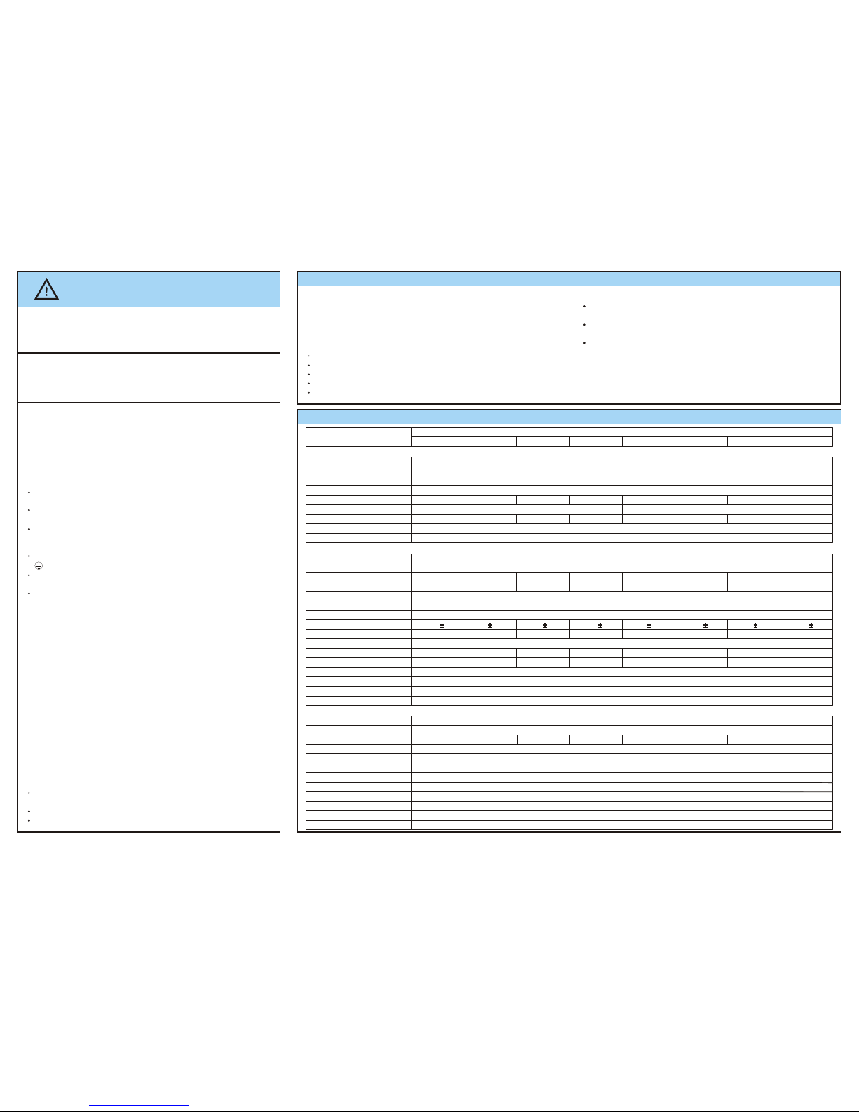
Technical Data
All specifications are typical at nominal line, full load,25 ; Unless otherwise specified.
o
C
Installation
Read Instructions!
Before working with this unit, read these instructions
carefully and completely. Make sure that you have
understood all the information!
Disconnect system from supply network
Before any installation, maintenance or modification work:
Disconnect your system from the supply network. Ensure that it
cannot be re-connected inadvertently!
In operation: No modifications!
As long as the unit is in operation: do not modify the
installation! The same applies also to the secondary side. Risk
of electric arcs and electric shock (fatal)!
Only connect/disconnect when the power
is off!
Convection cooling (See Fig.1)
Do not cover any ventilation holes!
Leave sufficient space around the unit for cooling!
Warning: High voltage! Stored energy!
The unit contains unprotected conductors carrying a lethal
high voltage, and components storing substantial amounts of
energy. Improper handling may result in an electric shock or
serious burn!
The unit must not be opened except by appropriately trained
personnel!
Do not introduce any object into the unit!
Keep away from fire and water!
Removal from DIN Rail (See Fig. 4)
Push the slider downwards (unlock). Gently lift
lower front edge of the unit (tipping) and remove.
Safety notes
Permissible mounting position: keep ventilation holes clear,
leave space for cooling! Recommended to have 25mm
free space at all sides:
Snap on support rail (See Fig. 2)
Tilt the unit slightly rearwards.
Fit the unit over top hat rail.
Slide it downward until it hits the stop.
Press against the bottom front side for locking.
Shake the unit slightly to check the locking action.
Before start of operation
Ensure appropriate installation
Warning! Improper installation / operation impair safety and
result in operational difficulties or complete failure of the unit.
The unit must be installed and put into service appropriately
by qualified personnel. Compliance with the relevant
regulations must be ensured. Before operation is begun the
following conditions must be ensured, in particular:
Connection to main power supply in compliance with
VDE0100 and EN50178.
With stranded wires: all strands must be secured in the
terminal blocks (potential danger of short circuit).
Unit and power supply cables must be properly fused; if
necessary a manually controlled disconnecting element must
be used to disengage from supply mains.
The non-fused earth conductor must be connected to the
" " terminal (protection class 1).
All output lines must be rated for the power supply output
current and must be connected with the correct polarity.
Sufficient air-cooling must be ensured.
Connection (See Fig. 3)
Use only commercial cables designed for the indicated
voltage and current values!
With flexible cables: make sure that all stranded cable are
secured in the terminal.
Ensure proper polarity at output terminals!
Model No.
DPP15-24
DPP25-5
DPP30-12 DPP30-24
DPP50-15 DPP50-24 DPP50-48 DPP100-24
Description
Input
Rated input Voltage
AC Voltage Range
DC Voltage Range
Frequency
Rated input Current
Inrush Current(115Vac/230Vac)
Efficiency Typ.
Power Factor Correction
115/230 Vac auto select
85-132 / 176-264
210-375 Vdc
2.2/1.2A
Typ.<35A / Typ.<55A
87%
1.1/0.7A1.1/0.7A
1.1/0.7A
0.7/0.4A0.7/0.4A
0.6/0.4A
0.4/0.25A
Typ.<35A
Typ.<35A / Typ.<45A Typ.<35A / Typ.<50A
115Vac / 230Vac
85 - 264Vac
90-375Vdc
50 / 60Hz
80% 78%
82%
84%
85% 86% 87%
meet EN61000-3-2 class A
Output
Turn on time
Voltage Rise Time
Overvoltage protection
Voltage trim range
Line regulation
Load regulation
Time & temp. Drift
Initial voltage setting
DC ON indicate(Green LED)
Ripple
Nominal Current
Rated over load protection
Current Limit
Holdup Time(115Vac/230Vac)
Voltage fall Time
Parallel Operation
>30 but <33Vdc
<6.7Vdc <18Vdc
>30 but <33Vdc
<20Vdc
>30 but <33Vdc
<66Vdc
>30 but <33Vdc
22.5-28.5 Vdc 5-6 Vdc 9.9-12.1 Vdc 22.5-28.5 Vdc 11.9-15.1 Vdc 22.5-28.5 Vdc 48-56 Vdc 22.5-28.5 Vdc
<1000mS after AC is applied to input at full resistive load
<150mS full resistive load
<0.5%
<0.5%
<1.0%
24.5V 1%
5V 1% 12V 1% 24.5V 1% 15V 1% 24.5V 1% 48V 1% 24.5V 1%
>18V >4V >7.92V >18V >9.52V >18V >38.4V >18V
<50m Vp-p
0.6A
5A
2.5A
1.3A 3.4A
2.1A
1.0A
4.2A
110%~150% 120%~135% 135%~160% 120%~150% 135%~155% 120%~150% 125%~145% 115%~140%
Fold Forward (Current rises, voltage drops to maintain constant power during overload p to max peak current)
>20ms / >25ms
<150mS from 95% to 10% rated voltage @ full load
Switch selectable Via front panel------DPP 100-24 model only
General
Emissions
Immunity
Approvals
EN61000-6-3,EN55011,EN55022 Class B Radiated and Conducted including Annex. A.
EN61000-6-2,EN61000-4-2 Level 4,EN61000-4-3 Level 3,EN61000-4-6 Level 3,
EN61000-4-4 Level 4 input and level 3 output. EN61000-4-5 level 4,EN61000-4-8,EN61000-4-11
EN60950-1,UL508 Listed, UL 60950-1, NEC Class 2 except DPP100-24, CE marked for EMC(89/336/EEC)
Temperature
Humidity
MTBF(MIL-HDBK-217F.GF25)
Case
Dimensions
H x W x D(inches / mm)
Weight
2.95 x 0.9 x 3.81
(75 x 22.8 x 96.7)
2.95 x 1.77 x 3.58
(75 x 45 x 91)
42.95 x 2.85 x 3.81
(75 x 72.5 x 96.7)
130g 260g 390g
Plastic
287,000 hrs 294,000 hrs 288,000 hrs 304,000 hrs 269,000 hrs 273,000 hrs 283,000 hrs 239,000 hrs
20%~90%RH
Storage:-25 to +85 , Operation-10 to+ 60 derating to half power from 60 to 70
oo o
CC C
Mounting (See Fig. 1)
JAN05-01
Fuse Rating (Internal)
T1AH,250V
T2AH/250V T3.15AH/250V
IP rating
IP 20
 Loading...