

Page 1
INSTRUCTION MANUAL
POWER SUPPLY
MODEL ____71____ SPEC._______
LAMBDA ELECTRONICS CORP.
COLLEGE POINT 56, N. Y.
Page 2
INSTRUCTION MANUAL
FOR
REGULATED POWER SUPPLY
MODEL 71
MANUFACTURED BY
LAMBDA ELECTRONICS CORP.
CORONA 68, NEW YORK
ISSUE A MODEL NO. 71
1-55-123 SERIAL NO. 1525
Page 3
INSTRUCTION MANUAL
FOR
REGULATED POWER SUPPLY
MODEL 71
1. GENERAL DESCRIPTION
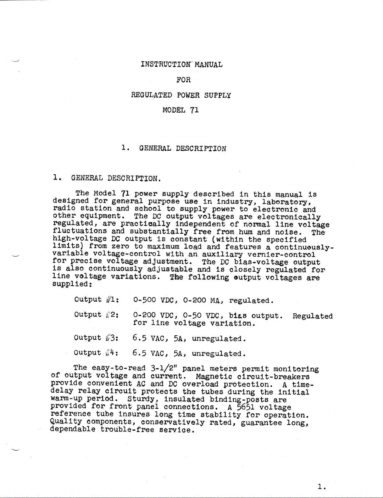
1. GENERAL DESCRIPTION.
The Model 71 power supply described in this manual is
designed for general purpose use in industry, laboratory,
radio station and school to supply power to electronic and
other equipment. The DC output voltages are electronically
regulated, are practically independent of normal line voltage
fluctuations and substantially free from hum and noise. The
high-voltage DC output is constant (within the specified
limits) from zero to maximum load and features a continuously-
variable voltage·control with an auxiliary vernier-control
for precise voltage adjustment. The DC bias-voltage output
is also continuously adjustable and is closely regulated for
line voltage variations. The following output voltages are
supplied:
Output #1: 0-500 VDC, 0-200 MA, regulated.
Output #2: 0-200 VDC, 0-50 VDC, bias output. Regulated
for line voltage variation.
Output #3: 6.5 VAC, 5A, unregulated.
Output #4: 6.5 VAC, 5A, unregulated.
The easy-to-read 3-1/2" panel meters permit monitoring
of output voltage and current. Magnetic circuit-breakers
provide convenient AC and DC overload protection. A time-
delay relay circuit protects the tubes during the initial
warm-up period. Sturdy, insulated binding-posts are
provided for front panel connections. A 5651 voltage
reference tube insures long time stability for operation.
Quality components, conservatlvély rated, guarantee long,
dependable trouble~free service.
1.
Page 4
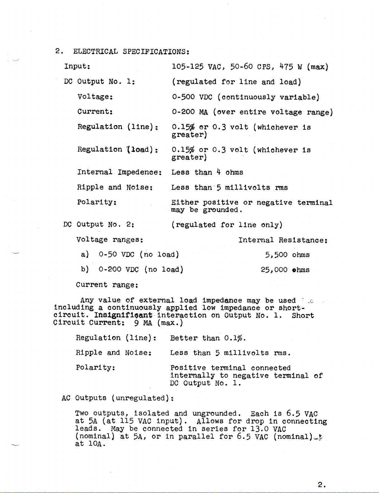
2. ELECTRICAL SPECIFICATIONS:
Input; 105-125 VAC, 50-60 CPS, 475 W (max)
DC Output No. 1; (regulated for line and load)
Voltage: 0-500 VDC (continuously variable)
Current; 0-200 MA (over entire voltage range)
Regulation (line); 0.15% or 0.3 volt (whichever is
greater)
Regulation (load); 0.15% or 0.3 volt (whichever is
greater)
Internal Impedence: Less than 4 ohms
Ripple and Noise: Less than 5 millivolts rms
Polarity: Either positive or negative terminal
may be grounded.
DC Output No. 2; (regulated for line only)
Voltage ranges: Internal Resistance:
a) 0-50 VDC (no load) 5,500 ohms
b) 0-200 VDC (no load) 25,000 ohms
Current range:
Any value of external load impedance may be used
including a continuously applied low impedance or short-
clrcult. Insignificant interactlon on Output No. 1. Short
Circuit Current: 9 MA (max.)
Regulation (line): Better than 0.1%.
Ripple and Noise; Less than 5 millivolts rms.
Polarity: Positive terminal connected
internally to negative terminal of
DC Output No. 1.
AC Outputs (unregulated):
Two outputs, isolated and ungrounded. Each is 6.5 VAC
at 5A (at 115 VAC input). Allows for drop in connecting
leads. May be connected in series for 13.0 VAC
(nominal) at 5A, or in parallel for 6.5 VAC (nom1nal)
at 10A.
2.
Page 5
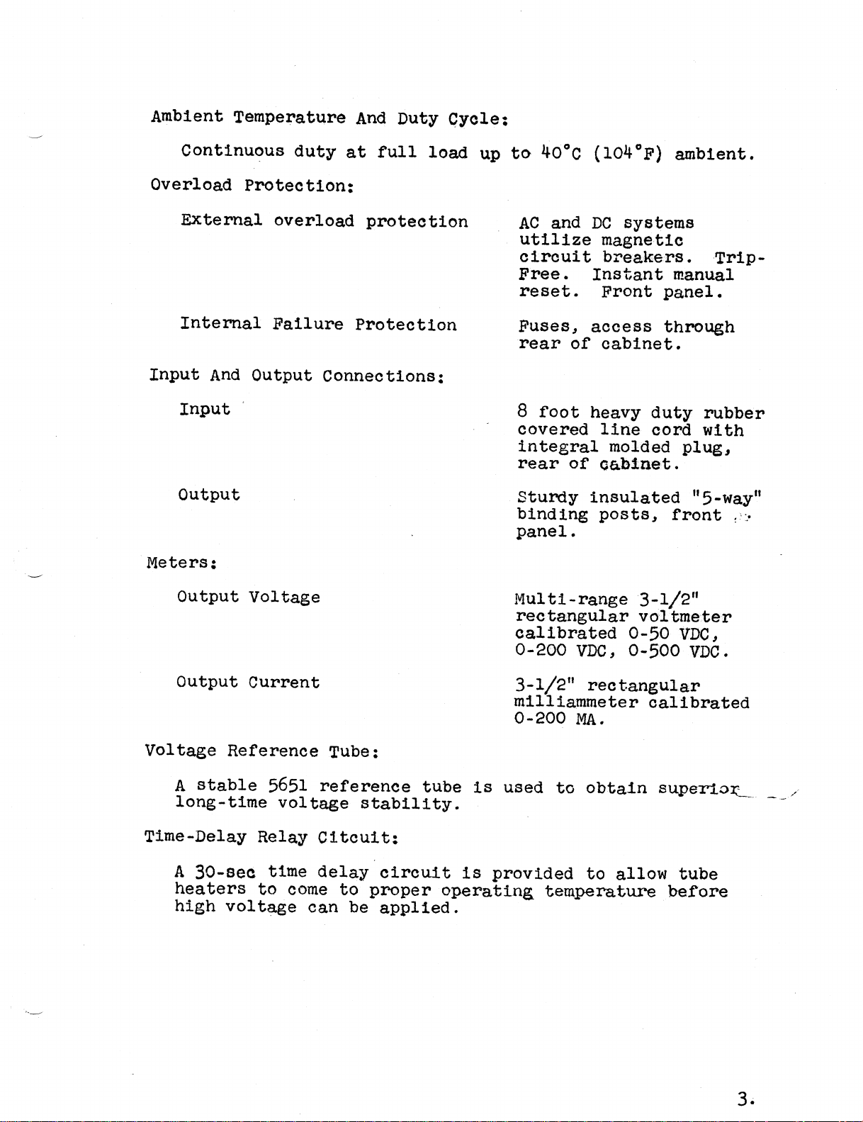
Ambient Temperature And Duty Cycle:
Continuous duty at full load up to 40°C (104°F) ambient.
Overload Protection:
External overload protection AC and DC systems
utilize magnetic
circuit breakers. Trip-
Free. Instant manual
reset. Front panel.
Internal Failure Protection Fuses, access through
rear of cabinet.
Input And Output Connections:
Input 8 foot heavy duty rubber
covered line cord with
integral molded plug,
rear of cabinet.
Output Sturdy insulated "5-way"
binding posts, front
panel.
Meters:
Output Voltage Multi—range 3-1/2"
rectangular voltmeter
calibrated 0-50 VDC,
0-200 VDC, 0-500 VDC.
Output Current 3-1/2" rectangular
mllliammeter calibrated
0-200 MA.
Voltage Reference Tube:
A stable 5651 reference tube is used to obtain superior
long—t1me voltage stability.
Time·Delay Relay Circuit:
A 30-sec time delay circuit is provided to allow tube
heaters to come to proper operating temperature before
high voltage can be applied.
3.
Page 6
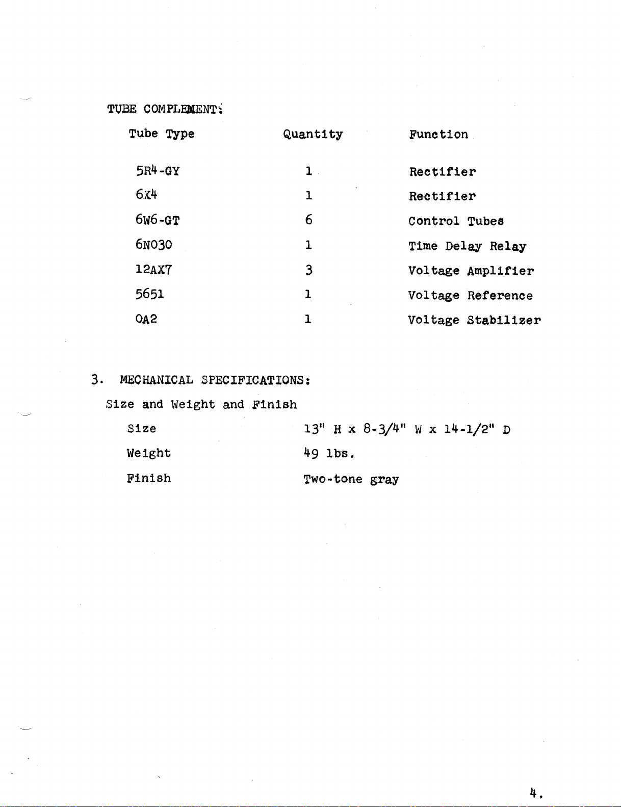
TUBE COMPLEMENT:
Tube Type Quantity Function
5R4·GY 1 Rectifier
6X4 1 Rectifier
6w6-GT 6 Control Tubes
6N030 1 Time Delay Relay
12AX7 3 Voltage Amplifier
5651 1 Voltage Reference
0A2 1 Voltage Stabilizer
3. MECHANICAL SPECIFICATIONS:
Size and Weight and Finish
Size 13" H x 8-3/4" W x 14-1/2" D
Weight 49 lbs.
Finish Two-tone gray
4.
Page 7
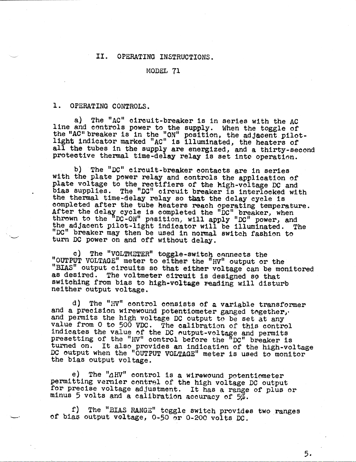
II. OPERATING INSTRUCTIONS.
MODEL 71
1. OPERATING CONTROLS.
a) The "AC" circuit-breaker is in series with the AC
line and controls power to the supply. When the toggle of
the "AC" breaker is in the "ON" position, the adjacent pilot-
light indicator marked "AC" is illuminated, the heaters of
all the tubes in the supply are energized, and a thirty-second
protective thermal time·delay relay is set into operation.
b) The "DC" circuit·breaker contacts are in series
with the plate power relay and controls the application of
plate voltage to the rectifiers of the high—voltage DC and
bias supplies. The “DC“ circuit breaker is interlocked with
the thermal time-delay relay so that the delay cycle is
completed after the tube heaters reach operating temperature.
After the delay cycle is completed the “DC" breaker, when
thrown to the ‘DC—ON" position, will apply "DC" power, and
the adjacent pilot—light indicator will be illuminated. The
"DC" breaker may then be used in normal switch fashion to
turn DC power on and off without delay.
c) The "VOLTMETER" toggle~switch connects the
"OUTPUT VOLTAGE" meter to either the "HV" output or the
"BIAS" output circuits so that either voltage can be monitored
as desired. The voltmeter circuit is designed so that
switching from bias to high·voltage reading will disturb
neither output voltage.
d) The "HV" control consists of a variable transformer
and a precision wirewound potentiometer ganged together,
and permits the high voltage DC output to be set at any
value from 0 to 500 VDC. The calibration of this control
indicates the value of the DC output—voltage and permits
presetting of the "HV" control before the "DC" breaker is
turned on. It also provides an indication of the high—voltage
DC output when the "OUTPUT VOLTAGE" meter is used to monitor
the bias output voltage.
e) The "/\HV" control is a wirewound potentiometer
permitting vernier control of the high voltage DC output
for precise voltage adjustment. It has a range of plus or
minus 5 volts and a calibration accuracy of 5%.
f) The "BIAS RANGE" toggle switch provides two ranges
of bias output voltage, 0-50 or 0-200 volts DC.
5.
Page 8
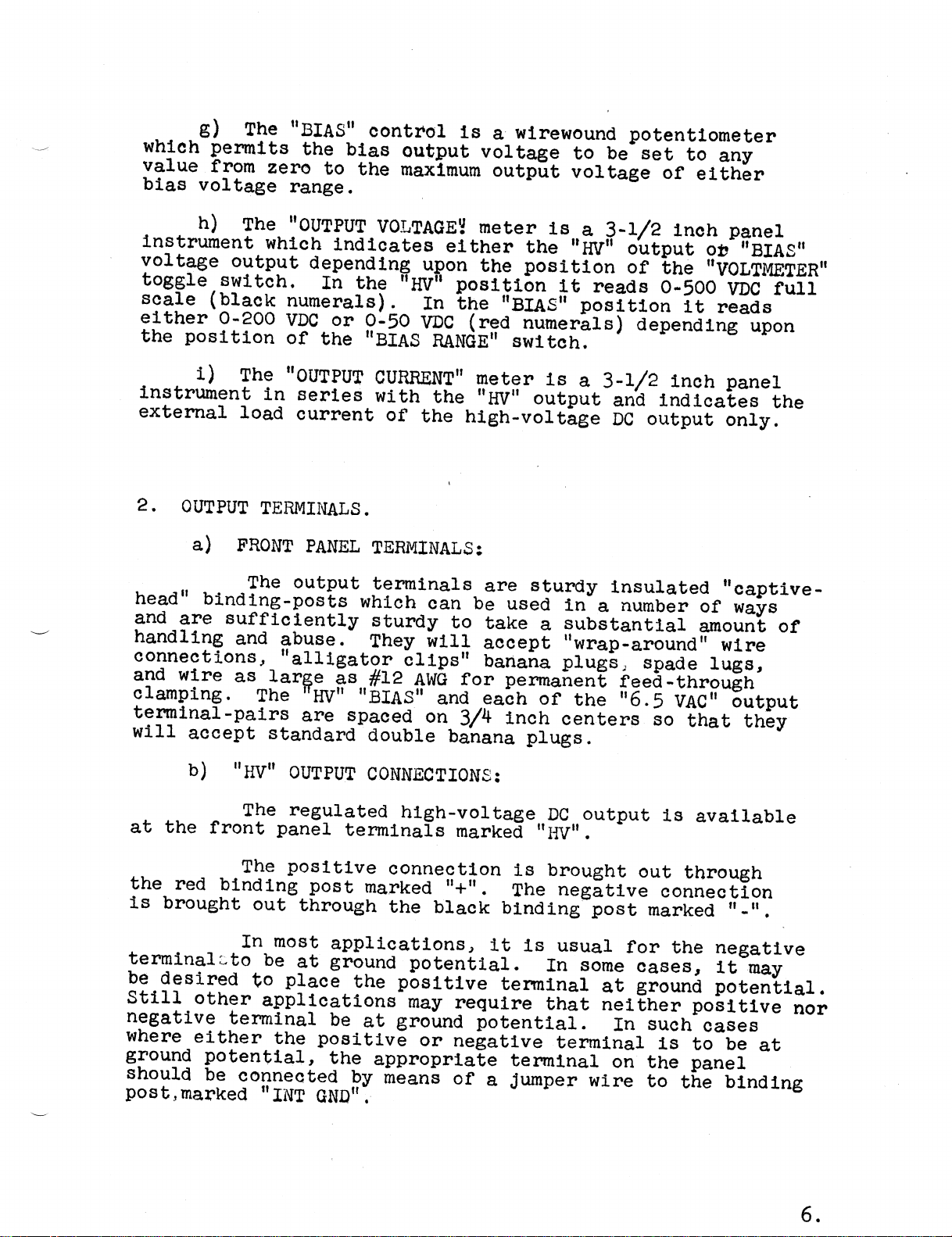
g) The "BIAS" control is a wirewound potentiometer
which permits the bias output voltage to be set to any
value from zero to the maximum output voltage of either
bias voltage range.
h) The "OUTPUT VOLTAGE" meter is a 3-1/2 inch panel
instrument which indicates either the "HV" output or "BIAS"
voltage output depending upon the position of the "VOLTMETER"
toggle switch. In the "HV" position it reads 0-500 VDC full
scale (black numerals). In the "BIAS" position it reads
either 0-200 VDC or 0-50 VDC (red numerals) depending upon
the position of the "BIAS RANGE" switch.
i) The "OUTPUT CURRENT" meter is a 3-1/2 inch panel
instrument in series with the "HV" output and indicates the
external load current of the high—voltage DC output only.
2. OUTPUT TERMINALS.
a) FRONT PANEL TERMINALS:
The output terminals are sturdy insulated "captive—
head" binding-posts which can be used in a number of ways
and are sufficiently sturdy to take a substantial amount of
handling and abuse. They will accept "wrap·around" wire
connections, "alligator clips", banana plugs, spade lugs,
and wire as large as #12 AWG for permanent feed—through
clamping. The 'HV" "BIAS" and each of the "6.5 vAc" output
terminal—pairs are spaced on 3/4 inch centers so that they
will accept standard double banana plugs.
b) "HV" OUTPUT CONNECTIONS:
The regulated high-voltage DC output is available
at the front panel terminals marked "HV".
The positive connection is brought out through
the red binding post marked "+". The negative connection
is brought out through the black binding post marked "—".
In most applications, it is usual for the negative
terminaleto be at ground potential. In some cases, it may
be desired to place the positive terminal at ground potential.
Still other applications may require that neither positive nor
negative terminal be at ground potential. In such cases
where either the positive or negative terminal is to be at
ground potential, the appropriate terminal on the panel
should be connected by means of a Jumper wire to the binding e
post, marked "INT GND".
6.
Page 9
For minimum output ripple, it is recommended
that either the positive or negative high voltage DC
output terminal be grounded.
c) "BIAS° OUTPUT CONNECTIONS:
The regulated DC bias-output voltage is available
at the front panel terminals marked "BIAS". The positive
"BIAS" connection is internally tied to the negative "HV"
connection and is brought out through the black binding
post marked "BIAS+" and "HV-". The negative "BIAS" connection
is brought out through the black binding post marked "BIAS-".
d) AC OUTPUT CONNECTIONS:
The AC output connections marked "6.5 VAC 5A"
provide two independent sources of unregulated voltage for
vacuum-tube heater—circuits. Both output sources are
available at the front-panel binding-posts. The AC output
terminals may be connected in series to provide 13.0 VAC
at 5 amperes, or in parallel to provide 6.5 VAC at 10 amperes.
The schematic diagram on the panel below the AC output binding
posts shows the proper connections of the terminals for
correct "phasing' of these voltages.
_SAFETY NOTICE_
DANGEROUS VOLTAGES EXIST IN THIS EQUIPMENT.
OBSERVE THE USUAL SAFETY PRECAUTIONS WHEN OPERATING OR
SERVICING THE EQUIPMENT TO AVOID SEVERE SHOCK OR INJURY.
3. PLACING MODEL 71 INTO OPERATION.
a) Both the "AC" and "DC" circuit·breakers snouid be
in the "OFF" position. The "HV" control and the "BIAS"
control should be in their extreme counter—clockwise positions,
the "/\HV" control in the center or "O" position.
b) Plug the power cord into a source of 115 volts AC
50/60 cycles.
c) Connect the desired AC and DC loads to the output
terminals of the supply. Note the schematic diagram on the
front panel showing proper phasing of the 6.5 VAC outputs
for series or parallel operation.
d) Throw the "AC" circuit breaker to the "ON" position.
The AC pilot indicator marked "AC" will be illuminated, and
6.5 volts AC will be present at the front panel bind1ng·posts.
The thermal time-delay circuit will start itS 30·second delay-
cycle.
7.
Page 10
e) After approximately 30 seconds, throw the "DC"
circuit-breaker to the "ON" position. The pilot-light
indicator marked "DC" will be illuminated, and the internal
plate-power·relay will close. If the "DC" circuit breaker
is thrown to the "ON" position before the 30 second time
delay has elapsed, the pilot indicator will not light nor
will the plate-power-relay close until the time-delay cycle
is complete.
f) After the pilot "DC" indicator 1e illuminated throw
the "VOLTMETER" selector switch to the "HV" position. Turn
the "HV" control clockwise to the desired DC output voltage
as indicated on the "OUTPUT VOLTAGE" voltmeter. The "/\HV"
vernier control may be utilized for precise voltage adjustment.
If an external load is connected to the "HV" output terminals,
the output current will be indicated on the "OUTPUT CURRENT"
meter.
g) If use of the "BIAS" output voltage is desired,
throw the "DC" breaker off, connect the bias-load to the
"BIAS" terminals, set the "BIAS RANGE" switch to the bias
voltage range desired, the "VOLTMETER" selector switch
to "BIAS" and the "BIAS" control to zero. Throw the "DC"
breaker on. Turn the "BIAS" control clockwise to the required
voltage as indicated on the proper red scale of the "0UTPUT
VOLTAGE" meter. The "OUTPUT VOLTAGE" meter may be used to
monitor the bias voltage, the calibration on the "HV" control
then serving as an indication of the "HV" output voltage.
h) If it is desired to turn off the DC output only,
use the "DC" circuit breaker, leaving the "AC" breaker in
the "ON" position. In this manner, the supply will be in
a standby condition ready for instant use.
CAUTION: Turning the supply on and off rapidly
by means of the "AC" breaker (with the DC breaker in the
"ON" position) may seriously damage or impair the life of
the high voltage rectifier tube. If less than one minute
elapses between the time the "AC” breaker is turned off and
turned on again (the time required for the protective
thermal time-delay relay to re—cycle) the "DC" breaker should
be kept in the ”OFF" position for at least 20 seconds after
the "AC" breaker is turned on to permit the rectifier heaters
to return to proper operating temperature.
4. OVERLOAD PROTECTION.
a) AC OUTPUT CIRCUITS:
An overload or short circuit of the 6.5 VAC 5A
output circuits will trip the "AC" circuit breaker shutting
off the entire supply. Removing the overeload and turning
8.
Page 11
the "AC" breaker on again will restore operation. If the
supply is off for more than one minute the thermal delay-
relay may re-cycle before DC voltage will be present at
the output terminals. (see CAUTION note in paragraph 3
above).
b) HIGH VOLTAGE DC OUTPUT CIRCUITS:
An overload or short circuit of the "HV" output
will trip the "DC“ circu1t—breaker releasing the plate-
power·relay and disconnecting the plate-voltage from the
rectifier tubes of both the high-voltage DC and bias supplies.
Removing the overload or short-circuit and throwing the "DC"
breaker to the "ON" position will restore operation
immediately.
c) DC BIAS OUTPUT CIRCUIT:
The bias output circuit is so designed that it
may be short·circuited for indefinitely long periods of
time without damage to any component or effect on the high
voltage DC output.
5. INTERNAL POWER SUPPLY FAILURE PROTECTION:
a) In general, external overload of the output voltage
circuits will result in tripping of the circuit breakers.
Internal failure of the power supply components may result
in tripping of the breakers or blowing of the internal
protective fuses mounted as the rear of the unit. Failure
of F1, the I/2 ampere 3AG "Slo-Blo" fuse, indicates failure
of a component of the bias reference supply. Failure of this
fuse will probably require servicing of the power supply.
Refer to Section III for maintenance data before servicing
of equipment or replacement of the fuse.
NOTE: Failure of this fuse will result in removal
of voltage from all DC output terminals.
b) F2, a 10-ampere 3AG "Slo-Blo" input line fuse
located adjacent to F1 provides protection against failure
of the powerstat TA-1, Lambda Part No. TA-549, and input
wiring. This fuse will also protect the power supply in
event that the unit is accidentally plugged into a 220 VAC
circuit or into a DC.circuit. This fuse will not fail in
the case of overloads of the DC or AC output circuits.
Thls protection is provided by the circuit breakers.
9.
Page 12
6. NOISE AND RIPPLE OUTPUT:
The noise and ripple output of the high-voltage
DC supply should be less then 5 millivolts rms and the
DC bias supply less than 5 millivolts rms at all voltages
and load conditions within the specifications. Measurement
of thls level of voltage may be made with an AC VTVM
capable of reading 5-8 millivo1ts rms. Meesurements of
these low values of voltege should be made using a shielded
cable connecting the power supply output to the AC VTVM.
It is recommended that either the positive or
negative terminal of the "HV" output be connected by a Jumper
wire to the "INT-GND" terminal for minimum ripple output.
7 . INTERNAL IMPEDANCE.
a) "HV" OUTPUT:
The internal impedance of the hlgh voltage DC
supply is approximately 4 ohms for DC. A 2 mfd oll-filled
paper capacitor is ln shunt with the DC output circuit
for two purposes: 1) to maintain this low value of output
lmpedence at audio, and at low and medium radio frequencies,
2) to provide a reservoir to supply transient currents of
short duratlon having peak values greater than 200 MA.
An additional external capacitor shunted across
the "HV" output will provide even lower AC output impedance
and allow even higher peak transient currents to be drawn.
For low impedance to high frequency RF·currents, the common
practice is to use a mica capacitor shunt close to the RF unit.
b) DC BIAS OUTPUT:
The internal resistance of the DC bias supply
O-200 VDC range is approximately 25,000 ohms. For low
impedance to AC, an external capacitor should be shunted
across the "BIAS OUTPUT" terminals. For low impedance to
high-frequency RF currents, the common practice is to use
a mica capacitor shunt close to the RF unit. The internal
resistance of the bias supply 0-50 VDC range is 5,500 ohms.
10.
Page 13
III. MAINTENANCE
SAFETY NOTICE
DANGEROUS VOLTAGES EXIST IN THIS EQUIPMENT.
OBSERVE THE USUAL SAFETY PRECAUTIONS WHEN OPERATING OR
SERVICING THE EQUIPMENT TO AVOID SHOCK OR INJURY.
1. GENERAL.
Under normal conditions no special maintenance
of the Model 71 regulated power supply is required except
for occasional tube replacement. In the event of failure,
or inability of the regulated DC output circuits to function
properly a list of typical symptoms and their probable causes
is given in paragraph "6" of this section.
2. REMOVAL OF POWER SUPPLY UNIT FROM CABINET.
If tube replacement or servicing of the unit is
necessitated, the power susply unit must be removed from
its cabinet. This is accomplished by removing the four
large diameter nickel-plated screws on the rear face of
the cabinet and sliding the unit out.
NOTE: It is not necessary to loosen any screws
other than the four mentioned above for removal of the
supply from the cabinet. At no time should removal of
the painted screws in the rear of the cabinet be attempted.
3. SERVICING OF POWER SUPPLY WHEN REMOVED FROM CABINET.
a) Upon removal of the cabinet, all tubes are made
accessible, and tube replacement is simply accomplished.
6W6-GT tubes and the 6N030 tube are secured to their
sockets by means of spring~type retainer clamps. These
retaining clamps must be depressed into and held in a
flattened position before removing these tubes. when
replacing the miniature type tubes, they should be inserted
into a pin straightener before putting them into the sockets
to avoid bending pins. Bent pins create strain on the glass
bases with the resulting possibility of breakage or cracking
in time. When tubes are replaced, adjustment of calibrating
potentiometers should be checked.
11.
Page 14
b) 6N030 TIME-DELAY·RELAY:
The 6N030 1s most readily checked under actual
operatlng conditions. If the power supply is turned on
from a cold start, and the "DC" circuit·breaker left in
the "ON" position, the internal plate-power-relay will
c1ose with an audible click, and the "DC ON" pilot light
lndlcator will be llluminated within 30 to 45 seconds.
At high AC line-voltages, the relay may close
1n as early as 20 seconds, at low line-voltages as late
as 1 minute. If the plate·power-relay closes much earlier
than 20 seconds or later than 1 minute from a cold start,
the 6N030 should be replaced.
c) 0A2 VOLTAGE REGULATOR TUBE:
Upon placing the Model 71 power supply into an
operating condition at any setting of output voltage the
0A2 should exhibit an lnternal pale purple glow. If tube
falls to glow or appears to flicker, the tube should be
replaced. If the new tube does not operate properly, the
circuit voltages should be checked against the circuit
diagram.
d) 5651 VOLTAGE REFERENCE TUBE:
No special check of the 5651 tube is required.
The tube operates normally with a bright orange glow on the
surface of its dlsc-shaped cathode. If the tube fails to
glow or appears to flicker, it should be replaced. If
then the fault is not remsved, a voltage check should be
made of the tube and its associated circuits. The voltage
across the 5651 should range between 82 and 92 VDC and
should not fluctuate.
4. ADJUSTMENT OF CALIBRATING POTENTIOMETERS R35 & R36:
If any of the tubes other than the rectifiers,
(5R4-GY and 6x4), the series control tubes, (6w6·GT), and
the time·delay relay, (6N030), are replaced, the calibrating
and alignment potentiometers, R35 and R36, may require
readjustment. This readjustment should be made according
to the following procedure:
a) With AC and DC circuit breakers in the "OFF"
position, zero-set the "Output Voltage" and "Output Current"
meters accurately.
b) Turn the "HV" control to its extreme clockwise
position. The pointer on the control knob should line up
with the 500 volt callbratlon line or very close to it.
12.
Page 15
If a major discrepancy exists, loosening of the two set
screws in the knob will permit readjustment of its position.
c) Set the "/\HV" control to its center or "0"
position.
d) Set the "Voltmeter" switch to the "HV" position.
e) With no external AC or DC load on the power supply,
turn both "AC" and "DC" circuit breakers on and allow the
supply to warm up for at least 10 mlnutes.
f) With the "HV" control set to 500, adjust R36 so
that the "Output Voltage" voltmeter reads 500 volts (black
scale).
g) Turn the "HV" control to the zero mark. Adjust
R35 so that the "Output Voltage" voltmeter reads zero.
h) Repeat steps "f" and "g" until the "HV" control
reads zero in its extreme counter clockwise position and
500 volts ln its extreme clockwise position.
5. OPERATIONAL CHECK.
a) REGULATION WITH LOAD:
After tubes have been replaced or the equipment
serviced, a simple check of the proper operation of the
0-500 VDC output circuit supply may be made by alternately
connecting and disconnecting a 200 MA load to the supply
with the 'Output Voltage" meter in the "HV" position.
Except for a transient kick of the meter needle when the
load is connected to the supply, the change in output
voltage should be barely perceptable (less than 1/10 of
1 division on the meter scale) for proper operation. An
AC VTVM capable of reading 5 millivolts rms may be employed
to check the noise and ripple level output of the supply
when making this check. Shielded leads should be employed
to connect the AC VTVM to the power supply output terminals.
Note that the "DC" "BIAS OUTPUT" circuit is not
regulated for load variations. (See Electrical Specifications)
b) REGULATION WITH LINE:
A Variac or Powerstat connected between the AC
power line and the input to the Model 71 may be employed
to check the regulation of the DC output circuits. With
the "Output Voltage" voltmeter ln the circuit being monitored
and the line voltage varied from 105 to 125 VAC, the change
in output voltage should be barely perceptible (less than
l/10 of 1 meter division) for proper operation.
13.
Page 16

6. TYPICAL POWER SUPPLY FAILURE CONDITIONS AND THEIR
PORTABLE CAUSES.
SAFETY NOTICE
DANGEROUS VOLTAGES EXIST IN THIS EQUIPMENT.
OBSERVE THE USUAL SAFETY PRECAUTIONS WHEN OPERATING OR
SERVICING THE EQUIPMENT TO AVOID SEVERE SHOCK OR INJURY.
Refer to the Schematic Diagram for proper
operating voltages in the equipment.
It is recommended that the input plug be removed
from the 115 VAC source when removing or replacing tubes.
OPERATING CONDITION REMEDY OR SOLUTION
a) AC circuit breaker Check AC output for overload
trips repeatedly or short circuit. Remove
overload condition.
b) DC circuit breaker 1) Check "HV" output load
trips repeatedly circuit for overload or short
circuit. Remove overload
condition.
2), If this does not eliminate
tripping of DC breaker, then
check for faulty 5R4-GY tube.
This tube should be tested in
a tube checker. If found
faulty, it should be replaced.
3) If tube is found to be
good or if replacement by a new
tube does not eliminate breaker
tripping, check capacitors,
C1 and C2A for breakdown or
short circuit. If these are
found to be cause of breaker
tripping, replacement of these
capacitors is required.
c) Presence of high DC 1) Shorted 6W6-GT tubes, V2
positive voltage at through V6. Shorting of tube
terminals compared to elements within tube envelope
that indicated on "HV" will result in loss of control.
dial, along with high A visual inspection of the
ripple and poor individual tubes may lead to
regulation. (no external identification of faulty tube.
load is applied to "HV" If this is not the case, each
output.) tube individually should be
removed while the output
voltage is monitored on the
"Output Voltage" meter.
14.
Page 17

If upon removal of any tube
V2-V6, this condition is
eliminated, replace this
faulty tube with a new tube.
2) Filament burnout of 12AX7.
V8. lf tubes V2-V6 ere all
found to be good, the 12AX7,
V8 may have a burned out
filament. This is slmply
checked for by replacing the
l2AX7 with a new tube.
3) Loss of bias supply voltage
will result in rise of output
voltage. If bias supply output
voltage approaches zero volts,
and 5651, V14 is extinguished
and voltage across C5A is zero,
the bias supply system fuse,
F1, 1/2 A has failed. Insert
a 1 Ampere AC ammeter in place
of the fuse and turn on the
supply. lf current exceeds
0.4 Amperes check 6X4, V10 for
short or gassy condition, and
C5A, CSB for shorted capacitors.
If any of these components are
found to be faulty, replace
these components.
4) Absence of voltage across
filter capacitors C5A, C5B.
check V10, 6X4 tube for open
or burned out filament. This
is most simply accomplished by
replacing tube with a new tube.
5) Presence of bias supply
input filter voltage and
absence of supply output
voltages a) 6W6—GT, V1
filament is burned out, replace
tube.
b) Filament burnout of 12AX7,
V12. This is easily checked
for by replacement with e new
tube.
15.
Page 18

d) Presence of positive 1) Filament burnout of l2AX7,
low level "HV" voltage as V11. This is easily checked
compared with that by replacement with a new
indicated on the "HV" dial, tube.
poor regulation and high
ripple. (no external load 2) Check voltage across
applied to "HV" output.) capacitor, C2A for voltage
conditions specified on
schematic diagram. If far
below indicated voltage, check
filter capacitor for open
circuit.
3) An abnormal increase of
reference supply voltage
results in reduced power
supply "HV" output voltage.
High bias supply voltage with
associated high reference
supply ripple voltage. This may
be the result of internal grid
to cathode or screen grid short of
6W6-GT, V1. Replace with a new
6W6-GT tube.
4) Burnout of V8, 12AX7 will
cause the bias voltage to rise.
It will have a similar effect
on the "HV" supply of greater
magnitude in the "HV" supply.
Therefore the net result of
filament burnout of this tube
is a rise of "HV" voltage.
e) Apparent satisfactory 6W6-GT tubes, V2 through V6,
operation at 200 MA load exhibit poor cut-off
with rise of ripple voltage characteristic. To check
at zero external load. cut—off characteristic,
operate at zero load and low
"HV" output voltage. Monitor
the "HV" output with a VTVM
or high impedance AC voltmeter.
Remove one tube at a time
until faulty tube is identified.
Faulty tube is identified by
return to normal of "HV"
output ripple voltage. Care
should be exercised in
handling 6W6-GT tubes to
prevent burning of hands due
to touching hot glass envelope.
In removing 6W6-GT tube,
depress retaining clamp
maintaining this position of
the clamp while tube is
removed.
16.
Page 19

f) Apparent satisfactory 1) Faulty 6W6-GT tubes, V2
operation at low current through v6, will cause
values with supply failure remaining 6W6-GT tubes to
at 200 MA external and carry excess load. Tubes
105 line. should be visually inspected
for filament burnout. If
burnout is not apparent, then
tubes should be checked on
a tube checker.
2) Faulty 5R4-GY, V9,
rectifier tube. A similar
condition applies to the 5R4-GY
rectifier. If tube drop is
excessive under load, then
operation at 200 MA and at
105 VAC line will be impaired.
The tube should be checked in
a tube checker, and if faulty,
it should be replaced.
g) Apparent instability Faulty bias and main amplifier
ln Power Supply Voltage, input tubes cause this voltage
drift of order 1 volt wandering. The tubes involved
magnitude or greater. are 12AX7 tubes, V11 and V12.
One tube should be first
replaced and the output voltage
monitored. If this condition
is not removed, replace the
second l2AX7 tube.
A schematic diagram of the
power supply will be found in
the rear of this manual. The
diagram contains typical
operating voltages for a
specific set of operating
conditions.
The pilot light indicator
lamps are NE51 neon lamps.
They are accessible from the
front panel by merely
unscrewlng the pilot·1ight dome.
_SAFETY NOTICE_
DANGEROUS VOLTAGES EXIST IN
THIS EQUIPMENT. OBSERVE THE
USUAL SAFETY PRECAUTIONS WHEN
OPERATING OR SERVICING THE
EQUIPMENT TO AVOID SEVERE
SHOCK OR INJURY.
17.
Page 20

7. MAINTENANCE OF THE POWERSTAT ("HV" CONTROL).
a) DETERMINING DEFECTIVE OPERATION:
When the brush contact of the "Powerstat"
indicates excessive wear (less than 1/32" of the carbon
brush extends from the brush holder) or arcing occurs when
the "Powerstat" is rotated with a load on the supply
resulting in high noise output from the equipment or hash
in RF equipment in the laboratory, the brush contact should
be examined. A properly adjusted "Powerstat" should not
arc or spark under load when the rotor shaft is turned.
If arcing is present, the "Powerstat" should be examined
and serviced.
b) SERVICING THE "POWERSTAT".
The "Powerstat" can be easily reached by removal
of the cabinet from the power supply. If closer examination
or adjustment of the powerstat is required, greater
accessibility is realized by removal of the front panel.
This is accomplished.by unscrewing the six large phillips
head screws on the front panel. After removing the six
screws, draw the panel forward then tilt it being careful
to clear the powerstat from the frame in doing so. The
powerstat brush is now free and clear. If wear is
indicated, replacement of the brush is effected by
loosening the two set screws in the brush holder and
removing the holder. Care must be exercised in replac1ng
the holder to insure the new holder very nearly assumes
its former position.
1. DIRTY OR PITTED COMMUTATOR SEGMENTS.
Dirty or pitted commutator segments may
be cleaned with carbon-tetrachloride.and/or sanded
lightly with fine crocus-cloth. Excessively pitted
commutator segments are a result of failure to replace
a worn brush or severe overload of the "Powerstat".
Replacement of the entire "Powerstat" assembly may
be necessary. (See paragraph 8a) Refer to Lambda
Part No. TA-549 when ordering.
8. SERVICE NOTES.
a) REMOVAL OF THE "HV" POWERSTAT AND PRECISION
POTENTIOMETER ASSEMBLY.
1. Remove the connections to the powerstat
and the precision potentiometer. Identify
leads to facilitate replacement of entire
assembly.
2. Remove the "HV" control knob.
18.
Page 21

3. Separate the assembly from panel by
unscrewing of the four phillips head
screws holding the unit to the front
panel.
4. Powerstat and precision potentiometer
assembly may now be separated from
panel.
b) REPLACEMENT OF POWERSTAT OR PRECISION
POTENTIOMETER.
1. Remove powerstat potentiometer assembly
from the equipment as per (a) above.
2. Loosen the set screws holding the flexible
coupling between the two units.
3. Loosen the nut securing the powerstat
to the bracket and remove the powerstat.
4. Replace the powerstat if required, insuring
that at the extremes of rotation of the
potentiometer shaft, the powerstat brush
takes symmetrical positions with regard
to the mounting screw in the rear of the
powerstat.
(NOTE: At no time should the stop collar screws
of the potentiometer be loosened and the collar
moved with regard to the potentiometer shaft.
These set screws are set hard and should remain
untouched.)
5. If the potentiometer is to be replaced,
after removal of the powerstat, loosen
the three pan head phillips head screws
securing the potentiometer to the bracket.
Replace the potentiometer with the new
unit. Refer to Lambda Part No. RW—559V
when ordering. Before tightening the
screws securing the potentiometer to the
bracket estimate the center to center
distance between the shaft of the
potentiometer and the stop screw in
the spacer plate. This is best done
with a pair of calipers. This distance
should approximate 29/64. The powerstat
should now be remounted, and the Millen
coupling joined to the powerstat and
potentiometer shafts. Rotation of the
potentlometer should now be tried and
the Millen coupling should be adjusted
so that at the extreme clockwise and
counter-clockwise positions of the shaft,
the brush holder of the powerstat should
take symmetrical positions with regard to
the mounting screw in the rear of the powerstat.
19.
Page 22

6. Check the assembly for smooth
rotation and reassemble into
equipment.
b) REPLACEMENT OF THE "VOLTMETER" AND "BIAS RANGE"
SWITCHES.
The replacement of either of these switches
can be facilitated by removing the panel as outlined
above.
_SAFETY NOTICE_
DANGEROUS VOLTAGES EXIST IN THIS EQUIPMENT. OBSERVE
THE USUAL SAFETY PRECAUTIONS WHEN OPERATING OR SERVICING
THE EQUIPMENT TO AVOID SEVERE SHOCK OR INJURY.
********************************************************
* *
* *
* _W A R R A N T Y_ *
* *
* We warrant each Instrument manufactured by us, and sold *
* by us or our authorized agents, to be free from defects *
* in material and workmanship; our obligation under this *
* warranty being limited to repairing or replacing any *
* instrument or part thereof (except tubes and fuses) *
* which shall, within one year after delivery to the *
* original purchaser, be returned to us with transpor- *
* tation charges prepaid, prove after our examination *
* to be thus defective. *
* *
* we reserve the right to discontinue instruments without *
* notice, and to make modifications in design at any time *
* without incurring any obligation to make such modifi- *
* cations to instruments previously sold. *
********************************************************
L A M B D A E L E C T R O N I C S C O R P .
103-02 Northern Boulevard
Corona, New York
Page 23

Page 24

NOTES
1. Tolerance of wirewound resistors is +/-5%, unless noted. SCHEMATIC DIAGRAM
2. Voltage rating of capacitors is 600 VDC, unless noted.
3. Tolerance of capacitors is +/-10%, unless noted. REGULATED POWER SUPPLY
4. Arrows indicate clockwise rotation of potentiometer shafts.
5. V Indicates connection to chassis. MODEL 71
6. * Indicates factory adjustments. See instruction manual.
7. (/) Indicates screwdriver slot. /L\
8. (2) Encircled numbers designate terminal board markings.
CONDITIONS OF VOLTAGE MEASUREMENT LAMBDA ELECTRONICS CORP.
b. "HV" control set to 500VDC, no load. "/\HV" control set to zero. CORONA NEW YORK
"BIAS" control set to zero.
c. Indicated voltages (italicized numbers) are average values.
d. Measurements made using 20,000 ohm per volt meter between "HV"
negative terminal and indicated points except as otherwise noted.
Page 25

Page 26

Page 27

Page 28

Page 29

Page 30

Page 31

Page 32

Page 33

Page 34

Page 35

Page 36

Page 37

Page 38

Page 39

Page 40

Page 41

Page 42

Page 43

Page 44

Page 45

Page 46

Page 47

Page 48

 Loading...