

Page 1

Shield by
USER MANUAL
Page 2

CONTENTS
How the System Works ��������������������������������������������������������������������������������������������������������������������������������2
Controlling the Security System �����������������������������������������������������������������������������������������������������������������3
Operating the Control Panel..............................................................................................................................................3
System Activation (Normal group) .............................................................................................................................................3
Partia l System Activatio n (Home group) .................................................................................................................................. 3
Disarmi ng the System on the Con trol Panel........................................................................................................................... 3
Disarmi ng the System Using an R FID Tag ................................................................................................................................ 3
Recording and Playing Back Voice Memos .............................................................................................................................3
Speed Dial .............................................................................................................................................................................................3
Making a C all ........................................................................................................................................................................................3
Recordi ng the Emergenc y Call Message .................................................................................................................................. 3
Restoring Factory Settings.............................................................................................................................................................3
Operat ing the System via An droid and iOS app s .........................................................................................................4
Creating an Account .........................................................................................................................................................................4
Settin gs in the Securit y System App .......................................................................................................................................... 4
Controlling Via SMS .............................................................................................................................................................6
Changing the Language .................................................................................................................................................................7
Disarming the Alarm via SMS ........................................................................................................................................................7
Arming the Alarm via SMS ..............................................................................................................................................................7
Partia l Alarm Activatio n via SMS (Home Mod e) ....................................................................................................................7
Two -Way Talk ....................................................................................................................................................................................... 7
Leaving a Voic e Memo .....................................................................................................................................................................7
Control th e System when Emerg ency Call Made ................................................................................................................. 7
Securi ty System Status via S MS ....................................................................................................................................................8
Storing Emergency Numbers .......................................................................................................................................................8
Storing Emergency SMS Numbers .............................................................................................................................................8
Saving SMS N umbers for RFID Tags ............................................................................................................................................ 8
Storing th e Speed Dial Numb er ...................................................................................................................................................8
Changing Sensor Names .................................................................................................................................................................9
Naming an R FID Tag .......................................................................................................................................................................... 9
Changing t he RFID Tag Name .......................................................................................................................................................9
Changing t he Exit and Entr y Delay Time ................................................................................................................................. 9
Settin g the Siren Volume and R ing Time ................................................................................................................................. 9
Changing the Disarm Password ...................................................................................................................................................9
Setting Single Zone Delay Time ..................................................................................................................................................9
Deleti ng Sensors, RFID Tags an d Remote Controls f rom the System .........................................................................10
Deleti ng Sensors from t he System ...........................................................................................................................................10
Deleti ng RFID Tags from the System........................................................................................................................................ 10
Deleti ng Remote Controls f rom the System .........................................................................................................................10
Restori ng the System Factor y Settings ...................................................................................................................................10
Other SMS Notications ................................................................................................................................................................10
Arming an d Disarming with a Fr ee Phone Call ....................................................................................................................10
Remote Control �������������������������������������������������������������������������������������������������������������������������������������������11
Produc t Layout .................................................................................................................................................................................11
Arm ........................................................................................................................................................................................................11
Disarm...................................................................................................................................................................................................11
Stay Mode ...........................................................................................................................................................................................11
Silent Mode ........................................................................................................................................................................................11
Emergency Calls ...............................................................................................................................................................................11
Connec ting a New Remote Con trol .........................................................................................................................................11
Page 3

RF ID Tag s �����������������������������������������������������������������������������������������������������������������������������������������������������11
Adding Ne w RFID Tags ...................................................................................................................................................................11
Sensors ���������������������������������������������������������������������������������������������������������������������������������������������������������12
PIR Motion Sensor ..............................................................................................................................................................12
Produc t Layout .................................................................................................................................................................................12
LED .........................................................................................................................................................................................................12
Internal Layout ..................................................................................................................................................................................13
Infrared Sensors................................................................................................................................................................................13
Tam per S witc h ...................................................................................................................................................................................13
LED .........................................................................................................................................................................................................13
Test Mode ............................................................................................................................................................................................13
Power Savin g Mode ........................................................................................................................................................................13
Connec ting a PIR Motion Se nsor ...............................................................................................................................................13
Install ing a PIR Motion Sens or ....................................................................................................................................................13
Testing a PIR Sen sor ........................................................................................................................................................................14
Magnetic Sensor .................................................................................................................................................................14
Produc t Layout .................................................................................................................................................................................14
LED .........................................................................................................................................................................................................14
Internal Layout ..................................................................................................................................................................................14
Installation Tips ..................................................................................................................................................................15
Installing the Magnetic Sensor ..................................................................................................................................................15
Electric Lock Output ................................................................................................................................................ 15
Installing the Control Panel ................................................................................................................................... 15
Assigni ng Sensors to Mo des ............................................................................................................................................15
Normal Mode .....................................................................................................................................................................................16
Home Mode........................................................................................................................................................................................16
Mode for Individual Groups ........................................................................................................................................................16
24-hour Mode....................................................................................................................................................................................16
Changing the Sensor Name .........................................................................................................................................................16
Test Mode ............................................................................................................................................................................................16
Technical Parameters ���������������������������������������������������������������������������������������������������������������������������������17
Control Panel .......................................................................................................................................................................17
PIR Motion Sensor ..............................................................................................................................................................17
Magnetic Sensor .................................................................................................................................................................17
Remote Control ...................................................................................................................................................................17
RFI D Tag ................................................................................................................................................................................ 18
Troubleshooting �����������������������������������������������������������������������������������������������������������������������������������������18
Page 4
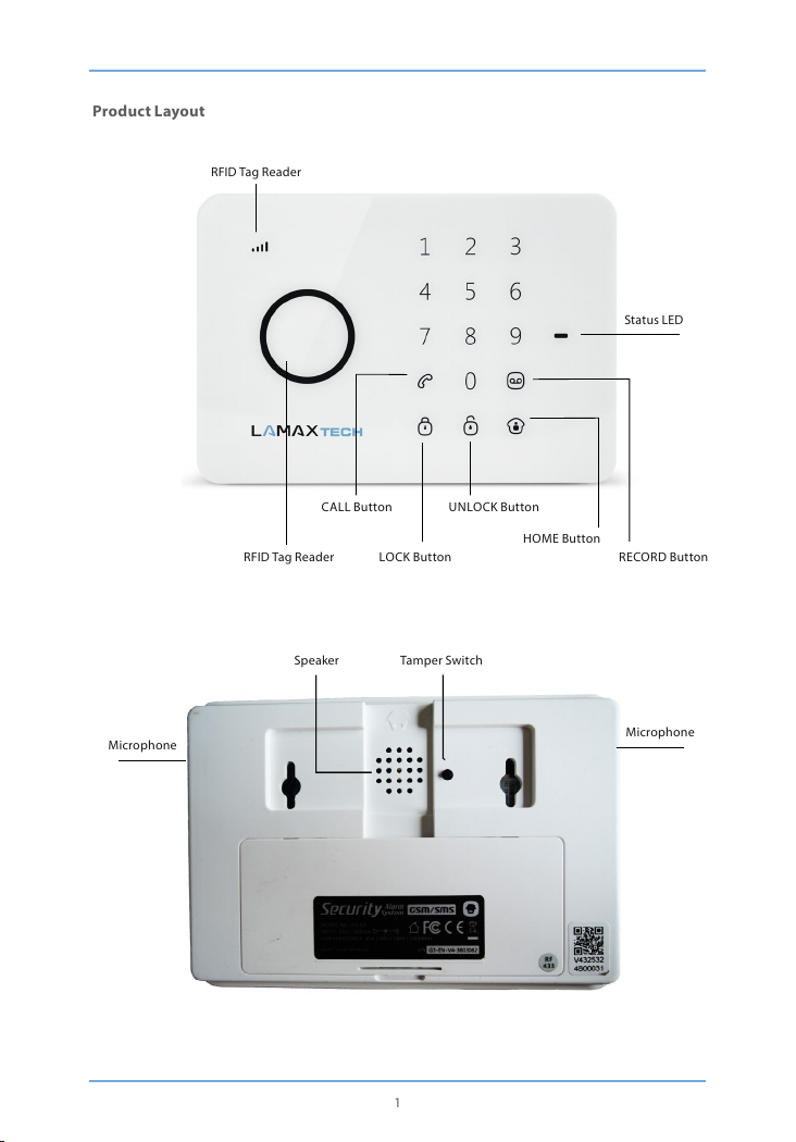
Product Layout
RFID Tag Reade r
Status LED
CALL Button UNLOC K Button
HOME But ton
RFID Tag Reade r LOCK Button RECORD Button
Speaker Tam per S witc h
Microphone
Microphone
1
Page 5
How the System Works
If the sensors detect an event, they send a signal to the control panel. An alarm is sounded and an
SMS is sent to all s tored phone numbers. If the alarm is not deactivated, the control panel then places
a call to all stored phone numbers. If an external siren (optional) is attached it sounds in parallel with
the syste m.
GETTING STARTED:
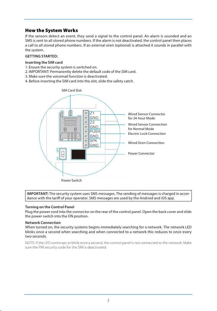
Inser ting the SIM card
1. Ensure the security system i s switched on.
2. IMPOR TANT: Permanently delete the default code of the SIM card .
3. Make sure th e voicemail function is deactivated.
4. Before i nserting the SIM ca rd into the slot, slide th e safety catch.
SIM Card Slot
Wired Se nsor Connecti o
for 24-hour Mode
Wired Sensor Connection
for Normal Mode
Electric Lock Connection
Wired Siren Connection
Power Connector
Power Switch
IMPORTANT: The securit y system uses SMS messages. The sen ding of messages is cha rged in accor-
dance with the tari of your operator. SMS messages a re used by the Android and iOS app.
Turning on the Control Panel
Plug the pow er cord into the connec tor on the rear of the co ntrol panel. Op en the back cover and sli de
the power s witch into the ON positi on.
Network Connection
When turned on, the security systems begins immediately searching for a network. The network LED
blinks once a second when searching and when connected to a network this reduces to once every
two seconds.
NOTE: If the L ED continues to blink once a seco nd, the control panel is no t connected to the net work. Make
sure the PIN security code for the SIM is deactivated.
2
Page 6

Controlling the Security System
The security system c an be controlled via SMS, via the Android o r iOS app or the control pa nel.
IMPORTANT: Always enter account names, sensors, RFID tags and remote controls without diacri-
tical marks.Always enter telephone numbers with the international dialling code starting with two
zeros instead of +.
Exampl e: 0044 123 456 789
Operating the Control Panel
System Activation (Normal group)
Press the “LO CK” button.All s ensors are activ ated.
Partial System Activati on (Home group)
Press the “H OME” button.The sen sors assigned to the H ome group are not activated when the control
panel is se t to Home Mode.
Disarming the System on the Control Panel
The sys tem can be disarme d on the control panel b y entering the four- digit securit y passcode (default
1234) and pressing t he “UNLOCK” but ton. One beep in dicates that the sy stem is disarme d. Three beeps
indicates that the securit y code has been enter ed wrongly.
Disarming the System Using an RFID Tag
Hold the RFID tag to the RFID reader (blue circle on the left of the control panel). Successful deactiva-
tion is conrmed by a beep.
IMPORTANT: In order to disarm t he system using the R FID tag, the control p anel must be connec ted
to the mains. RFID tags can only b e used to disarm the sy stem, anot to arm it.
Recordi ng and Playing Back Voi ce Memos
Press the “RECORD” button for 3 seconds and record a voice message. Maximum length of a voice
message is 10 seconds. If the message is less than 10 seconds, press the “RECORD” button ag ain when
you have completed the message. Voice message can be played back by holding an RFID tag up to
the reader.
Speed Dial
Press the “CALL” button to immediately call the security company on a preset number. Press “CALL”
again to end the call.
Making a Call
It is possib le to directly cal l any phone using the se curity system . Just select the p hone number on the
control panel and press “CALL”. The call uses the mic rophone and speaker built into the control panel.
Press “CALL” again to en d the call.
Recording the Emergency Call Message
When the control panel alar m is triggered it call s all emergency telephone numbe rs and plays a mess-
age. To record the m essage press the “H OME” button, then enter the securit y passcode (default 1234),
press “HO ME” again and nally press “RECORD”. You have 10 seconds to record the message.
Restoring Factory Settings
Restori ng factory s ettings, or do ing a “hard reset ” is perform ed whenever the SI M card is changed. T his
can also be done manually by pressing the tamper switch at the back of the control panel ve times
in three seconds.
3
Page 7

Operating the System via Android and iOS apps
Shield by L AMAX Tech can be contro lled via an app. The ap plication can be d ownloaded from t he App
Store (iOS) or G oogle Play.
IMPORTANT: Android and iOS apps use SMS.
Creating an Account
Start the app on your phone an d press “Add Account”.
Select the name of the security system (without diacritical marks) and enter the phone number of the
SIM card that is in the control panel (with the international dialling code, beginning with 00). Once an
account is cre ated, it appears on the home page.
Settin gs in the Securit y System App
The app has a w ide range of controls a nd settings divided into three scre ens.
Basic Operation
Arm
Press to act ivate the system in no rmal mode (see Assigning Sensors to M odes).
Stay
Press to act ivate the system in ho me mode (see Assigning Sensors to Mo des).
Disarm
Press to disarm the system. Only 24-hour mode remains active (see Assigning Sensors to Modes).
Voice Memo
Press to record a voice message on the control panel. Maximum length of a voice message is 10 se-
conds. A voice message can be played by holding th e RFID tag to the reader.
Two-Way Talk
Press to request a two-way t alk. The system immediately calls back to your phone number so you can
have a conversation via the contro l panel.
4
Page 8

Setting Phone Numbers and Choosing the Language
Selec t System Language
Press to select the security system language. Note that the app language itself is always the same as
the default language set in the OS of your phone. To change the app language you must change the
OS language on your phone.
IMPORTANT: We recommend that th e app language is the s ame as the system la nguage. If not, com -
munication between the system and app may not work properly.
Phone Numbers and SMS Numbers
Press to enter the emergency phone numbers. Emergency telephone numbers are the numbers the
securit y system calls or SMSs when the alarm is triggered or the system is disarmed. For each phone
number you can tick whether you want to send an SMS, call or both. International numbers should
begin with two zeros.
SMS Numbe r for RFID Tags
This numb er is used in the event tha t the alarm is disable d using the RFID tag.O nly one number can b e
entered. Enter international numbers starting with two zeros.
Delete R FID
Clears RFI D tags from the memor y.
Store Spe ed Dial Number
Here you can set a speed dial number. Speed dial is used for communicating between the control pa-
nel and a set telephone numb er, and is activated by pr essing “CALL” on the control pan el.
5
Page 9

Further Settings
Change Zone Name
The security systems allows you to name up to 9 dierent sensors. Maximum length is 30 characters.
Sensor names should be entered without diacritical marks.
Change RFI D Tags Name
The secu rity systems a llows you to name 4 die rent RFID tags. Enter R FID tag names with out diacritical
marks. If a tag is used to disarm the alarm, the system sends a tex t message to the telephone number
you have set.
IMPORTANT: Sending SMS only wo rks if the RFID tag i s named and the admin istrator phone nu mber
to which it is sent is set.
Entry an d Exit Delay
With this security system it is possible to set up a time delay when arming or disarming. When set up,
the contro l panel beeps ever y second and it s frequency i ncreases in the las t 15 seconds . The maximum
delay time is 300 seconds.
Siren Volume and Ring Time
Press to adjus t the volume and length of the alarm. The volume can be adjus ted to three levels. At th e
lowest volume level the control panel does not emit any sound. The maximum length of the alarm
tone is 9 minutes.
Single Zo ne Delay Time
It is possible to set the entry and exit time delay for individual sensors. The maximum time delay is
300 seconds.
Controlling Via SMS
System set tings can be changed by sending an SMS to the control panel SIM card phone number. The
complete r ange of SMS commands c an be recalled by s ending one, two o r three question ma rks accor-
ding to the group. Each command has its own code.
?
- Disarm - 0
- Arm - 1
- Home Mod e - 2
- Two-Way talk - 3
- Call-b ack voice memo - 4
- Settin g Inquiry - 00
6
Page 10

??
- Store alarm p hone No. - 5
- Store alarm SMS No. - 6
- Store SMS No. for RFID tags - 7
- Store spee d dial phone No. - 8
???
- Zone name – 91-99
- RFS tags SMS notice - 10
- Entry and exit delay time - 11
- Siren volum e and ringing time - 12
- Disarm pa ssword - 13
- Single zon e delay time - 14
Changing the Language
Each language has its own four-digit code. Set the language by sending an SMS with the four-digit
code to the co ntrol panel SIM car d number. Upon recei pt the language cha nge is made and the con trol
panel sends back a conrmation SMS.
NOTE: The language can also be set using the app.
Disarming the Alarm via SMS
By sending a text message with one question mark, a list of commands with numeric codes are dis-
played. Disarming the alarm is number “0”. To disarm, sen d an SMS with this code to the control panel
SIM card number. When successfully disarmed, the control panel sends a conrmation SMS.
Arming the Alarm via SMS
The alarm c an be armed in the s ame way as disarmi ng. The code to ac tivate the syst em is “1”. To arm the
system send this code via SMS to the control panel SIM card number. When armed, the control panel
sends a conrmation SMS.
Partial Alarm Activation via SMS (Home Mode)
Putting the alarm in home/stay mode works the same way as fully arming the system. The activation
code is “2”. Send this code via SMS to the control panel SIM card number to put the system into home
mode. Upon activation , the control panel sends a conrmation SMS.
Two-Way Talk
To activate a two-way call send the code “3” to the control panel SIM card number. The system calls
back imme diately to your phone a nd you can speak to some one through the contr ol panel.
Leaving a Voice Memo
To leave a message send the code “4” to the contro l panel SIM card phone number. The syste m imme-
diately calls back to your phon e number. Answer the phone and leave a messag e of no longer than 10
seconds . The message can be p layed back by holding a n RFID tag to the reader on the control panel.
Control th e System when Emerg ency Call Made
When the al arm is triggered, t he control panel cal ls the preset numbe rs. The followin g commands can
be made by pressing the corresponding number code.
Command Code Number
Disarm 0
Arm 1
Turn O Siren 6
Turn On Siren 9
Two-Way Talk *
Play Emergency Message #
7
Page 11

Security System Status v ia SMS
Send the code “00” to the control panel SIM card number to request the status information of the
security system.
Example:
System a rmed
- Entry and exit delay time: 0sec
- Single zon e delay time: 30sec
- Siren volum e: 2
- Siren ringing time: 5min
- Disarm pa ssword: 1234
Storing Emergency Numbers
Emergency numbers are the numbers that the system calls when the alarm is triggered or the system
has been disarmed. To see a list of e mergency phone numbers, send the code “5” to the control panel
SIM card number.
Copy the received SMS text message and paste it into a new message. Then ll in the phone numbers
that you want called in the event of an emergency. We recommend entering the full telephone number
including the international dialling code. The text message can contain multiple phone numbers and
should be s ent back to the control panel SIM card numb er.
Example:
Information about emergency telephone numbers may look like this:
TEL:
1. 0 04 412345678 9
2. 004 41234567 89
3. 004 41234 5678 9
4. 004 41234 5678 9
5. 004 4123 456789
After submitting the new emergency numbers, the control panel conrms receipt and changes the
settings.
IMPORTANT: Changes to the system can only be ma de by stored telephone numbers.
Storing Em ergency SMS Nu mbers
Emergency SMS numbers are the numbers that the system sends an SMS to when the alarm is trig-
gered or the system is disarmed. To see a list of emergency SMS numbers, send the code “6” to the
control panel SIM.
Copy the received SMS text message and paste it into a new message. Then ll in the numbers you
want added. We recommend entering the full phone number including the international dialling code.
A text me ssage can contain mu ltiple phone numb ers and should be se nt to the control panel S IM card
number.
Saving SMS N umbers for RFID Tags
This number is used in the event that the alarm is disarmed using a RFID ta g. To nd the number, send
the code “7 ” to the control panel SIM card number.
Copy the received SMS text message and paste it into a new message. Then ll in the number that
you want called when a RFID tag is used. We recommend entering the full phone number, including
the international dialling code. Then send th e message to the contro l panel SIM card phon e number.
Storing th e Speed Dial Numb er
This number is used for speed dialling. Speed dialling is done by pressing the “CALL” button on the
control panel. To nd the number, send t he code “8” to the contro l panel SIM card number.
Copy the received SMS text message and paste it into a new message. Then ll in the your chosen
speed dial number. We recommend entering the full phone number, including the international dia-
lling code. Then send the SMS me ssage to the control pa nel SIM card phone number.
8
Page 12

Changing Sensor Names
Each sensor can be named individually. The rst nine sensors (1-9) can be named using up to a ma-
ximum 30 characters. The names of sensors 10 and above can not be renamed. To check the sensor
name, send the code “91” - “99” to the con trol panel SIM card number.
Copy the rece ived SMS text mess age and paste it into a ne w message. Then ll i n the sensor name and
send it back to the control pane l SIM card number.
Naming an RFID Tag
RFID tags can be named. If the owner of the tag disarms the alarm, the system sends a text message
to the prese t phone number
IMPORTANT: Sending SMS onl y works if the RFID ta g is named and the adm inistrator phon e number
to which it is sent is set.
Changing the RFID Tag Name
Each RFID t ag can be named. To nd out t he name of the tag, se nd the code number “10” to t he control
panel SIM c ard number.
Copy the received SMS text message and paste it into a new message. Then ll in the tag names and
send the SMS b ack to the control pan el SIM card number. Th e text message c an contain several n ames.
Example:
Informat ion about the names of individual chip s might look like this:
Change RFID tag names:
1. Da d
2. Mum
3. To mas
4. Sarah
Changin g the Exit and Entr y Delay Time
With this security system it is possible to set up a time delay when arming or disarming the alarm.
When set up, the control panel beeps every se cond and its frequency increases in the last 15 seconds.
To determine the length of the time delay, send the code number “11” to the control panel SIM card
number.
Copy the received SMS text message and paste it into a new message. Then set the length of the time
delay and se nd it back to the control p anel SIM card number. Ma ximum time delay is 300 seconds.
Setting the Siren Volume and Ring Time
To determine th e length and volume of t he alarm, send the co de number „12“ to the control panel S IM
card number.
Copy the received SMS text message and paste it into a new message. Fill in the alarm length and
volume and s end it back to the contro l panel SIM card numbe r.
Changing the Disarm Password
To determine the deactivatio n passcode, send cod e “13” to the control panel SIM card number.
Copy the received SMS text message and paste it into a new message. Fill in the new deactivation
password and send it back to the control panel SIM c ard number.
Settin g Single Zone Delay T ime
With this security system it is possible to set the entry and exit delay time for single zones. To deter-
mine the length of the delay time for each zone, sent the code number “14” to the control panel SIM
card number.
Copy the rece ived SMS text mess age and paste it into a new m essage. Then set t he length of the dela y
time and send it back to the control panel SIM card number. The maximum length of the time delay
is 300 seco nds.
9
Page 13

Deleti ng Sensors, RFID Tags an d Remote Controls f rom the System
All accesso ries (sensors, R FID tags and remot e controls) can be del eted from the sy stem by pressing th e
tamper s witch 3 times in 3 seconds. The control pan el emits two beeps when the accessory is cleared.
Deleti ng Sensors from th e System
The numer ic code for dele ting sensors fr om the system is “21”. By sendin g the code to the contro l panel
SIM phone number the sensors are deleted fr om the system. Upon activation, the control panel s ends
a conrmati on SMS.
Deleti ng RFID Tags from the System
The numeric code for deleting RFID tags from the system is “22”. By sending the code to the control
panel SIM phone number the RFID tags are deleted from the system. Upon activation, the control
panel sends a conrmation SMS.
Deleting Remote Controls from the System
The numeric code for deleting remote controls from the system is “21”. By sending the code to the
control panel SIM phone number the remote controls are deleted from the system. Upon activation,
the control panel sends a conrmation SMS.
Restoring the System Factory Settings
The numer ic code to restore f actory se ttings of the sy stem is “000 0”. By sending this cod e to the control
panel SIM card phone number, the system is reset to its original settings. Upon activation, the control
panel sends a conrmation SMS.
Other SMS Notications
These notications are se nt to the rst stored te lephone number for SMS alerts. T he alerts warn of :
- Low battery in the control p anel or sensors
- B reak in the power suppl y to the control panel
- If the tamper switch on the control panel or sensors has been activated (SMS is sent to all phone
numbers).
Arming and Disarming with a Free Phone Call
The secu rity system ca n be armed by callin g the control pane l SIM card number. When i t starts ring ing,
hang up. The control panel wil l then call you back. T he alarm is then arme d.
The security system can be disarmed by calling the control panel SIM card number. Do not hang up,
wait and the system will automatically disar m. The control pane l will not call you back .
IMPORTANT: When arming and disarming, voicemail must be turned o on the control panel SIM
card.
10
Page 14

Remote Control
Product Layout
SOS
UNLOCK
LED
Arm
To arm the alarm, press the “LOCK” button on the remote control. The LED lights up and you will hear
a beep. Th e alarm is now armed.
Disarm
To disarm the alarm, press the “UNLO CK” button on the rem ote control. The LED lig hts up and you will
hear a beep. The alarm is now dis armed.
Stay Mode
To activate st ay mode, press the “ HOME” button on t he remote control. A ll sensors in the n ormal group
will be arm ed. All sensors in th e home group will be dis armed.
Silent Mo de
To activate silent mode, press and hold the “HOME” button on the remote control for one second and
then press t he “LOCK/UN LOCK” button for t hree seconds. T he securit y system silent m ode is activate d/
deacti vated. The system can now be controlled without disturbing the neigh bours.
Emergency Calls
Pressing the “SOS” button on the remote control immediately triggers an alarm, irrespective of
whether t he security sys tem is armed or not.
Connecting a New Remote Control
To pair a remote control, enter the password into the control panel and press the “RECORD” button.
The but ton will light up. The n press any button o n the remote contro l and it will beep. Th e remote con-
trol is now pa ired. If you hear t he control panel b eep twice, the r emote control has al ready been pai red.
HOME
LOCK
RFID Tags
RFID tags are used to disarm the s ecurity syste m. Disarm by placing t he RFID tag on the reade r.
Adding Ne w RFID Tags
To pair a new RFID tag, enter the password into the control panel and press the “RECORD” button.
The but ton will light up. Now hol d the RFID tag near the reader on the control p anel. When you hear a
beep the R FID tag is paired. If th e control panel bee ps twice, it means the t ag has already bee n paired.
IMPORTANT: RFID tags only wor k when the control pan el is connected to th e mains.
11
Page 15

Sensors
The secu rity system is mo st eective whe n the sensors are wel l positioned. De termine which sites y ou
would like to monitor and where to place the sensors. We recommend placing the control panel near
the front d oor. The magnetic s ensor is designe d to be mounted on wi ndows, doors o r French windows.
Motion sensors should ideally be placed in the corner to cover the entire space. Place the smoke de-
tector on the ceiling and the r unning water detec tor in the kitchen or bathroom near the si nk or bath.
PIR Motion Sensor
The PIR sensor is a pet immune motion detector. This mean that pets will not trigger the alarm when
you are not ho me and the securit y system is armed.
Product Layout
Motion Sensors
1. Motion Sensors
2. LED
3. Wall Mount
LED
Continuous blinking: motion sensor is performing auto-testing
One blink : motion is detected
Two blinks: three-minute tes t is complete, sensor will go into sleep mo de
Blinkin g every 3 secs: low ba ttery warning
NOTE: If the b attery is running low, the device will send an SMS alert.
LED
12
Page 16

Internal Layout
LED
Infrared Sensor
Tam per S witc h
Infrared Sensor
Mode Settings
Carefully remove the cover from the back of the sensor.
Infrared Sensors
Infrared sensors detect movement. Therefore always keep them clean. Do not touch the sensor.
Tamper Switch
If the PIR mot ion sensor cover is ope ned, the tamper sw itch sends a signal to the control panel.
LED
The LED on the front of PIR motion s ensor can be switch ed on or o by moving the jumper.
Back of the P IR Motion Sensor
Test Mode
Press the test button and when auto-testing is complete the PIR motion sensors sends a signal to the
control panel.
Power Savin g Mode
PIR sensor a utomatically g oes into power savi ng mode if moveme nt is detected t wice in three minu tes.
If movement is detected within the next three minutes it goes back into working mode. During those
three minutes the sensor cannot be activated and does not send a signal to the control panel. If the
sensor detects movement within the following three minutes, it goes into power saving mode for a
further three minutes.
Connecting a PIR Motion Sensor
IMPORTANT: When pairing a sensor, make sure the other sensors are not detecting movement.
Either cover these sensors or temporarily move them to a room where there will be no movement.
The sensors that are includ ed are paired with the control panel by de fault.
To pair a PIR motion s ensor, enter the control p anel passcode and press the “RECORD” b utton. The bu-
tton will l ight up. Press the test bu tton on the back of th e sensor twice or ma ke a movement in front of
the motion sensor. When you hear the beep, the PIR sensor is paired. If the control panel b eeps twice,
it means the s ensor has already been paired.
Instal ling a PIR Motion Sen sor
Do not install sensor directly on a window, close to air conditioning, heating, refrigerator, oven, in
direct sunlight or in places where the temperature often varies. Avoid installing two sensors opposite
each other or covering the same range.
13
Page 17

NOTE: The ideal height to install the sensor is 2.2 metres .
Fix the sensor mount in place with the screws included. Insert the sensor into the mount. Position the
sensor to cover the desired area . Test the func tioning of the sens or by putting it into test mode.
IMPORTANT: Do not move the sens or up or down when using the pet recognition function.
Testing a PIR Se nsor
1. Once the motion sensor is installed and active, proceed to testing. Press the test button once and
navigate around the room from left to right and right to left.
2. When the sensor detec ts motion, the LED blinks twice.
3. Adjust the angle if necessary and repeat th e procedure.
Magnetic Sensor
Product Layout
Sensor
Magnet
LED
Single blink: opening of door/window detected
Blink ever y 3 seconds: low bat tery warning
NOTE: If the b attery is running low, the device will send an SMS alert.
Internal Layout
Tam per S witc h
Mode Settings
Tamper Switch
If the magn etic sensor cover is opened, the tamper switch sends a signal to the control pa nel.
14
Page 18

Installation Tips
Installing the Magnetic Sensor
The magnetic sensor can be installed on windows, doors or any other object that can be opened or
closed. T he sensor consis ts of two part s, the larger sen sor part and the s maller magnet p art. The sens or
attach es to the frame and the ma gnet to the moving par t.
When installed correctly, the LED on the magnetic sensor blinks once when the two parts are separa-
ted by more than a centimetre. When closed, the spacing between the two parts must not be more
than one centimetre.
Both par ts of the magnetic se nsor attach with double sided tap e or screws.
Do not install the magnetic sensor on metal surfaces or in places where there are a large number of
metal parts. Ensure the LED blinks when th e window or doors op ens.
IMPORTANT: On both parts of the magnetic sensor there is an arrow. Parts must be xed with the
arrow pointing towards you.
Connecting the Magnetic Sensor
1. Ensure the sens or is mounted next to the magnet at a dist ance of less than one cent imetre.
2. Enter the p asscode into the contro l panel and press “RE CORD”.
3. Record bu tton lights up.
4. Separa te the two parts of the sensor from ea ch other at a distance of greater than one centimetre.
5. The sensor s will record the eve nt. When the sens or is successfully p aired, the contro l panel will bee p.
If the control panel beeps t wice, it means the sensor has already be en paired.
Electric Lock Output
The PUSH and GND connector of the electric lock can be connected to the PUSH and GND at the rear
of the contro l panel.
Once the security system is connected to the electric lock and disarmed, the control panel sends a
signal to the l ock and unlocks it.
NOTE: Doo rs equipped wit h an electric loc k automatically unlo ck when there is a power fa ilure. We strongly
recommend connecting a backup power device.
Installing the Control Panel
The contro l panel can be mounte d directly on the wa ll or using the stand on a ny at surface.
Installing on the Wall
The control panel can be mounted on the wall using the bracket and screws included. Insert the con-
trol panel into the bracket from top to bottom. The bracket ensures that the tamper switch is conti-
nually depressed.
Instal ling on a Flat Surface
Using the st and, the control pan el can be installe d on any at surface. Ins ert the control pan el into the
stand from top to bottom. T he stand ensures tha t the tamper switch is co ntinually depress ed.
IMPORTANT: Pressing the tamper switch several times resets th e system.
Assigning Sensors to Modes
Each sensor can be assigned to one of four dierent modes. The security system recognizes home
mode, normal mode, 24-hour mode and single zone mode.
IMPORTANT: Before you set the security system, decide which sensor to put in which group. If you
want to change which group the sensor is in, the sensor must be disconnected from the control
panel.
The gure b elow shows the senso r switch setting for each group.
15
Page 19

Normal Mode Home Mode Mode for Individual Groups 24-hour Mode
Normal Mode
The magnetic detectors included are set to normal mode by default. They are set to D0, D1 and D2. In
normal mo de, the sensors are active whenever the alarm is armed .
Home Mode
The motion sensors included are set to home mode by default. They are set to D0 and D1. If home
mode is activated, when the sensors in the group detect movement they send a signal to the control
panel but the alarm will not sound. Home mode allows you to partially secure your home but move
freely around your at or house.
Mode for Individual Groups
The detectors can be set to register after a time delay either individually or in groups. This setting is
typically used for magnetic detectors on a window or door. For example, if the user is not carrying a
remote control they will have sucient time to disarm the alarm after opening the door before the
alarm sounds.
24-ho ur Mode
The 24-h our mode settin g is recommended by default for dete ctors such as the smo ke detector. If the
sensor set to 24-hour mode is activated, it sends a signal to the control panel regardless of whether
the syste m is armed or not.
Changing the Sensor Name
The motion detectors and magnetic door detectors included are paired to the system. Each sensor
is numbered according to the sequence in which they are paired (zone 1 – zone 9). The names of the
individual sensors can be subsequently changed.
Test Mode
The system can be set to test mode. In this mode the system beeps three times instead of the alarm
soundin g. To turn test mode on, p ress the “UNLOCK” bu tton three cons ecutive times . When the control
panel beeps, test mode is activated. After 10 minutes, the system automatically switches out of test
mode. Test mod e can be turned o manually by pressing th e “LOCK” button.
16
Page 20
Technical Parameters
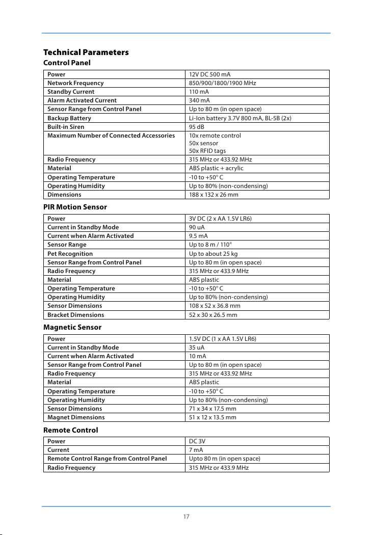
Control Panel
Power 12V DC 500 mA
Network Frequency 850/900/1800/190 0 MHz
Standby Current 110 mA
Alarm Activated Current 3 40 mA
Sensor Range from Control Panel Up to 80 m (in op en space)
Backup Battery Li-Io n battery 3.7V 8 00 mA, BL-5B (2x)
Built-in Siren 95 dB
Maximu m Number of Conne cted Accessorie s 10x remote control
Radio Frequency 315 MHz or 433.92 MHz
Material ABS plasti c + acrylic
Operating Temperature -10 to +50° C
Operating Humidity Up to 80% (non-condensing)
Dimensions 188 x 132 x 26 mm
PIR Motion Sensor
Power 3V DC (2 x A A 1.5V LR6)
Current in St andby Mode 90 uA
Current wh en Alarm Activa ted 9.5 mA
Sensor Range Up to 8 m / 110°
Pet Recognition Up to about 25 k g
Sensor Range from Control Panel Up to 80 m (in op en space)
Radio Frequency 315 MHz or 433.9 MHz
Material ABS plasti c
Operating Temperature -10 to +50° C
Operating Humidity Up to 80% (non-condensing)
Sensor Dimensions 108 x 52 x 36.8 mm
Bracket Dimensions 52 x 30 x 26 .5 mm
Magnetic Sensor
Power 1.5V D C (1 x AA 1.5V LR6)
Current in St andby Mode 35 uA
Current wh en Alarm Activa ted 10 mA
Sensor Range from Control Panel Up to 80 m (in op en space)
Radio Frequency 315 MHz or 433.92 MHz
Material ABS plasti c
Operating Temperature -10 to +50° C
Operating Humidity Up to 80% (non-condensing)
Sensor Dimensions 71 x 34 x 17.5 mm
Magnet Dimensions 51 x 12 x 13.5 mm
Remote Control
Power DC 3V
Current 7 mA
Remote Control Range from Control Panel Upto 80 m (in op en space)
Radio Frequency 315 MHz or 433.9 MHz
50x sensor
50x RFID ta gs
17
Page 21

Material ABS + PC plast ic
Operating Temperature -10 to +50° C
Operating Humidity Up to 80% (non-condensing)
Dimensions 58 x 31 x 9.5 mm
RF ID Tag
Circuit EM4100 CMOS
Radio Frequency 125 KHz
Dimensions 30 x 30 x 6 mm
Electrical products should not be disposed of with other waste. According to European Directive
2002/96/EC on electrical waste, electronic equipment and its components must be individually han-
ded in at coll ection points .
NOTE: If you replace the battery in the device with an unapproved type, you risk damage or re.
Use only batteries approved according to the technical parameters.
Troubleshooting
If the Shield by LAMAX Tech is not f unctioning prop erly, try the follow ing solutions.
Control panel will not tur n on.
- Make sure it is p roperly connec ted to the power suppl y.
- Make sure the p ower is on.
Remote control does not work.
- Make sure the L ED lights up when you pre ss the unlock butto n.
- Check that the remote is prope rly paired with the co ntrol panel.
- Ensure that th e remote control and control panel in range.
Magnetic sensor does not work.
- Check that the LED lights up when the door/window is opened.
- Ensure that th e remote control and control panel are in ra nge.
- Make sure the s ecurity syste m is armed.
- Make sure the d istance betwee n the sensor and magnet is less than one centimetre.
PIR motio n sensor is triggered but control p anel alarm does no t sound.
- Press the test bu tton on the senso r when the securi ty system is arm ed. If the control p anel alarm does
not sound , re-pair the sens or and control panel .
- Ensure that th e sensor band contro l panel are in range.
- Make sure the s ensor is not in standby mode.
- Make sure the b attery is not dea d.
Control panel does not respond to SMS commands.
- Check the SI M card is inserted correctly.
- Ensure the SIM card was inserted before the sy stem was turned on.
- Check that the SIM card is connec ted to the GSM standard network.
- Ensure the SIM card has active credit.
- Make sure the SIM card has SMS and calling enabled.
When ala rm is triggered, yo u do not receive any SMS .
- Ensure that th e emergency numb er has been stored in the control panel memory.
- Do not disa rm the alarm immediately after it is tr iggered, other wise the call is interr upted.
- Make sure the SIM card has active c redit.
Security system trig gers the alarm, b ut there is no sound .
- Make sure the s ound is not muted on the control panel. Reset the alarm sire n via SMS or the app.
Magnet ic sensor batter y life.
- Magnet is powered by a single AA battery which should last approximately 8-12 months. This de -
pends on how often the doors/windows are opened and closed.
18
Page 22

PIR motio n sensor batter y life.
- Sensor is powered by two AA batteries which should last approximately 8-12 months. This depends
on the comin gs and goings in the space.
Control panel does not re spond to RFID tag.
- Control panel only respon ds to RFID tags when connected to the mains.
- Make sure the R FID tag is paired with the control panel . If not, pair it.
Control panel does not se nd SMS when armed/di sarmed with an RFI D tag.
- Check the stored e mergency telep hone number and the n ame of the RFID tag.
Sensor, rem ote control and other accessories d o not respond aft er the control pane l has been mo-
ved.
- Press the tamper s witch on the rear of the co ntrol panel thre e times in three secon ds. All connecti ons
between the control panel and accessories will be deleted. Make sure you do not activate the alarm
by pressing t he tamper switch multiple times whe n installing the contr ol panel.
I receive d an SMS that the phone n umber is unauthor ized.
- SIM card is se t to display caller.
- Phone numb er is set as an emergen cy alarm number.
GSM netw ork LED blinking .
- If the GSM network LED is blinking once per second, it is searching for the network. If the GSM LED
blinks o nce every two seco nds, it is connecte d to the network.
Motion sensor does not work properly.
- If the PIR motion sen sor records an event t wice in three minutes , it automatically s witches to standby
mode. If no motion is detected over the following three minutes it switches back to normal mode.
During th ese three minutes th e sensor is inacti ve and does not send any s ignal to the control p anel. If
movement is d etected within three minutes, st andby is extended.
Exclusi ve importer of L AMAX product s in EU:
elem6 s. r.o., Braškovská 308/15, 16100 Praha 6
http://www.lamax-electronics.com.
Misprints and changes in the manual are reserved.
19
Page 23

Shield by
BENUTZERHANDBUCH
Page 24
INHALT
Funktionsprinzip des Systems ��������������������������������������������������������������������������������������������������������������������2
Betätigung des Sicherheitssystems �����������������������������������������������������������������������������������������������������������3
Betätigung des Kontrollpanels .........................................................................................................................................3
Aktivierung des Systems (Normale Gruppe) ..........................................................................................................................3
Teilweise Aktivierung des Systems (Home-Gruppe) ...........................................................................................................3
Deaktivierung des Systems auf dem Kontrollpanel ............................................................................................................3
Deakt ivierung des Syst ems mit Hilfe von RFI D-Chip .......................................................................................................... 3
Aufnahme und Überspielung einer Sprachnachricht ........................................................................................................3
Schnellwahl ..........................................................................................................................................................................................3
Anruf........................................................................................................................................................................................................3
Aufnahme einer Notrufnachricht................................................................................................................................................3
Einführung des Systems in die Fabrikeinstellung ................................................................................................................3
Bedienung durch Applikation für Android und iOS ....................................................................................................4
Kontoerstellung..................................................................................................................................................................................4
Einstellung des Sicherheitssystems mit Hilfe der Applikation .......................................................................................4
Betätigung über SMS ...........................................................................................................................................................6
Sprachwechsel .................................................................................................................................................................................... 7
Deakt ivierung des Ala rms mit Hilfe von SMS ......................................................................................................................... 7
Aktiv ierung des Alarm es mit Hilfe einer SM S .........................................................................................................................7
Teilweise Ak tivierung des A larms mit Hilfe ein er SMS (Home-M odus) .......................................................................7
Beidseitige Kommunikation .......................................................................................................................................................... 7
Sprachnachricht hinterlassen ....................................................................................................................................................... 7
Betätigung des Systems während eines Notanrufs.............................................................................................................7
Modus des Sicherheitssystems mit Hilfe einer SMS ............................................................................................................8
Nottelefonnummer speichern .....................................................................................................................................................8
Speiche rn der Notrufnu mmer für SMS ..................................................................................................................................... 8
Speiche rn der SMS-Num mer für RFID- Chips .........................................................................................................................9
Speichern der Nummer für die Schnellwahl ..........................................................................................................................9
Änderung der Sensorbezeichnung ............................................................................................................................................9
Benennung des RFID-Chips ........................................................................................................................................................... 9
Änderung der Bezeichnung des RFID-Chips .......................................................................................................................... 9
Änderung der verzögerten Einschaltung ................................................................................................................................9
Einstell ung der Länge und L autstärke des A larms ............................................................................................................10
Passwortänderung für die Deaktivierung des Alarms .....................................................................................................10
Einstellung des verzögerten Ein- und Ausschalten der Einzelzone ...........................................................................10
Löschen der Sensoren, RFID-Chips und der Fernbedienungen aus dem System ................................................10
Löschen der Sensoren aus dem System .................................................................................................................................10
Löschen d er RFID-Chip s aus dem System..............................................................................................................................10
Löschen der Fernbedienungen aus dem System ...............................................................................................................10
Rückstellung des Systems in die Fabrikeinstellungen .....................................................................................................10
Weitere SMS-Hinweise ...................................................................................................................................................................10
Aktivierung und Deaktivierung mit einem Anruf kostenlos .........................................................................................11
Fernbedienung �������������������������������������������������������������������������������������������������������������������������������������������11
Produktabbildung ........................................................................................................................................................................... 11
Aktivierung .........................................................................................................................................................................................11
Deaktivierung....................................................................................................................................................................................11
Home-Modus..................................................................................................................................................................................... 11
Stiller Modus ......................................................................................................................................................................................11
Notruf ....................................................................................................................................................................................................11
Anschluss der Fernbedienung ...................................................................................................................................................11
Page 25

RFID-Chi ps ���������������������������������������������������������������������������������������������������������������������������������������������������12
Anschluss der neuen RFID-Chips ..............................................................................................................................................12
Sensoren ������������������������������������������������������������������������������������������������������������������������������������������������������12
PIR-Bewegungssensor ......................................................................................................................................................12
Produktabbildung ...........................................................................................................................................................................12
Diode .....................................................................................................................................................................................................13
Produktabbildung innen ..............................................................................................................................................................13
Infrarote Sensoren ...........................................................................................................................................................................13
Schutzschalter ...................................................................................................................................................................................13
Diode .....................................................................................................................................................................................................13
Testmodus ..........................................................................................................................................................................................13
Sparmodus .........................................................................................................................................................................................13
Anschluss des PIR-Bewegungssenso rs ...................................................................................................................................13
Installation des PIR-Bewegun gssensors ................................................................................................................................14
Testen des PIR-Bewegungssensors ..........................................................................................................................................14
Magnetsensor .....................................................................................................................................................................14
Produktabbildung ...........................................................................................................................................................................14
Diode .....................................................................................................................................................................................................14
Produktabbildung innen ..............................................................................................................................................................15
Installationstipps ...............................................................................................................................................................15
Installation des Magnetsensors ............................................................................................................................ 15
Ausgang des Elektroschlosses ...................................................................................................................................................15
Installation des Kontrollpanels ..................................................................................................................................................16
Einstel lung der Senso ren in Modi ..................................................................................................................................16
Normalmodus ...................................................................................................................................................................................16
Home-Modus.....................................................................................................................................................................................16
Modus für die Einzelgruppe ........................................................................................................................................................16
24-Stunden-Modus .........................................................................................................................................................................16
Änderung der Sensorbezeichnung ..........................................................................................................................................17
Testmodus ..........................................................................................................................................................................................17
Technische Parameter��������������������������������������������������������������������������������������������������������������������������������17
Kontrollpanel ......................................................................................................................................................................17
PIR-Bewegungssensor ......................................................................................................................................................17
Magnethalter .......................................................................................................................................................................17
Fernbedienung ...................................................................................................................................................................18
RFID- Chip .............................................................................................................................................................................18
Problemlösung �������������������������������������������������������������������������������������������������������������������������������������������18
Page 26

Produktabbildung
Diode des GSM-Netzes
Statusdiode
Tas te ANRUF Ta ste ENTSPERREN
Tas te HOME
RDIF-Chipleser Tas te SPERREN Tas te AUFNAHME
Lautsprecher Schutzscha lter
Mikrofon
Mikrofon
1
Page 27

Funktionsprinzip des Systems
Falls die Sensoren ein Ereignis au fzeichnen, senden sie ein Signal ins Kontrollpanel. Die Station schal -
tet ein akustisches Warnsignal ein und sendet eine SMS an alle gespeicherte Telefonnummern. Falls
der Alarm nicht deaktiviert wird, das Kontrollpanel tätigt einen Anruf an alle gespeicherte Telefon-
nummern. Wenn die externe Sirene angeschlossen ist (wahlweise), schaltet sie ein akustisches Warn-
signal par allel mit der Station e in.
WIR BEGINNEN:
Einlegen der SIM-Karte
1. Vergewissern Sie sich, dass das Sich erheitssystem ausgeschaltet ist.
2. WICHTIG: Löschen Sie den Default-Code dauerhaft von der SIM-Karte.
3. Wenn die Funk tion des Anrufb eantworters ak tiv ist, schalten S ie sie aus.
4. Bevor Sie die SIM-Kar te in den Schlitz einl egen, schieben Si e die Sicherung des Sc hlitzes aus.
Schlitzfürdie SIM-Kar te
Drahtverbindung der Sensorenfür den
24-Stunden-Modus
Drahtverbindung der Sensorenfür den
Normalmodus
Anschluss des Elektroschlosses
Drahtverbindung der Sirene
Stromanschluss
Hauptschalter
WICHTIG: Das Sicherheitssystem verwendet für seinen Betrieb die SMS-Nachrichten. Der SMS
-Versand ist mit der Gebühr gemäß dem aktuellen Tarif Ihres Operators belegt. SMS-Nachrichten
verwenden die Applikationen Android und Apple.
Einschaltung des Kontrollpanels
Schließen Sie den Speisekabel in den Konnektor auf der Rückseite des Kontrollpanels an. Dann klap-
pen Sie die Rückseite ab und schalten Sie den Hauptschalter in di e Position ON.
Netzanschluss
Das Sicherheitssystem beginnt sofort nach der Einschaltung einen Netzanschluss auszusuchen. Die
Netzdiode blinkt in diesem Fall einmal pro Sekunde. Sobald das System ans Netz angeschlossen wird,
die Diode reduziert di e Blinkfrequen z auf 2 Sekunden.
BEMERKUNG: Wenn die Diode einmal pro Sekunde blinkt, das Sicherheitspanel ist nicht ans Netz an-
geschloss en. Kontrollieren Sie, ob die Sicherheits PIN der SIM -Karte deaktiviert ist.
2
Page 28

Betätigung des Sicherheitssystems
Das Sicherungssystem kann man durch SMS-Nachrichten, durch die Applikation für Android oder iOS
oder auf dem Kontrollpanel betätigen.
WICHTIG: Geben Sie die Namen der Konten, der Sensoren, RFID-Chips und Fernbedienungen immer
ohne diakritische Zeichen ein. Die Telefonnummer geben Sie immer mit der internationalen Vorwahl
mit zwei Nullen anstatt + e in.
Beispie l: 0044 123 456 789
Betätigung des Kontrollpanels
Aktivierung des Systems (Normale Gruppe)
Drücken Si e die Taste „SPERREN“. Alle Sensoren si nd aktiviert .
Teilweise Aktivierung des Systems (Home-Gruppe)
Drücken Sie die Taste „HOME“. Die Sensoren, die in der Home-Gruppe eingestellt sind, werden nicht
aktiviert, wenn auf dem Kontrollpanel der Home-Modus eingestellt ist.
Deaktivierung des Systems auf dem Kontrollpanel
Das System kann auf dem Kontrollpanel durch Drücken eines vierstelligen Sicherheits-Codes (Standar-
deinstellung 1234) deaktiviert werden und Drücken der Taste „ENTSPERREN“. Ein Piepton signalisiert
die Deaktivierung des Systems. Drei Pieptöne kennzeichnen, dass ein falscher Sicherheits-Code ein-
gegeben wurde.
Deakt ivierung des Syste ms mit Hilfe von RFID -Chip
Halten Sie den RFID-Chip in der Nähe vom Leser (blauer Kreis im linken Teil des Kontrollpanels). Erfol-
greiche Deaktivierung des Systems wird durch einenPiepton signalisiert.
WICHTIG: Für Deaktivierung des Systems durch RFID-Chip muss das Kontrollpanel ans Stromnetz
angeschlossen sein. RFID Chips können nur für die Deaktivierung des Systems verwendet werden,
nicht für se ine Aktivierun g.
Aufnahme und Überspielung einer Sprachnachricht
Drücken Sie die Taste „AUFNAHME“ für 3 Sekunden und nehmen Sie eine Sprachnachricht auf. Die
Maximallänge einer Sprachnachricht ist 10 Sekunden. Wenn die Nachricht kürzer als 10 Sekunden ist,
drücken Sie nach ihrem Ende wieder die Taste „AUFNAHME“. Die Sprachnachricht können sie durch
Drücken des RFID-Chiplesers abspielen.
Schnellwahl
Durch Drücken der Taste „ANRUF“ ruft das Sicherheitssystem sofort die vorgewählte Nummer an.
Durch ein wiederholtes Drücken der Taste „ANRUF“ beenden Sie den Anruf.
Anruf
Mit Hilfe des Sicherheitssystems ist es möglich, direkt ein beliebiges Telefon anzurufen. Wählen Sie
einfach die Telefonnummer auf dem Kontrollpanel und drücken Sie die Taste „ANRUF“. Das Telefon-
gespräch verläuft mit Hilfe eines Mikrofons und eines Lautsprechers, der im Kontrollpanel eingebaut
ist. Durch ein wiederholtes Drücken der Taste „ANRUF“ wird das Gespräch beendet.
Aufnahme einer Notrufnachricht
Bei Aktivierung des Alarms ruft das Kontrollpanel alle Notrufnummern an und überspielt die Na-
chricht. Die Nachricht können Sie durch Drücken der Taste „HOME“ aufnehmen, dann geben Sie das
Sicherh eitspasswort (St andardeinstellu ng 1234) ein und drü cken Sie wieder die Taste „ HOME“ und an-
schließ end die Taste „AUFNAHME“. Jetz t haben Sie 10 Sekund en für die Hinterla ssung einer Nachri cht.
Einführung des Systems in die Fabrikeinstellung
Einführung des Systems in die Fabrikeinstellung oder „harter Reset“ wird immer beim Wechsel der
SIM-K arte durchgeführt. Harter Reset kann auch durch Drücken des Schu tzschalters auf der Rückseite
des Kontrollpanels fünfmal in drei Sekunden hervorgerufen werden.
3
Page 29

Bedienung durch Applikation für Android und iOS
Shield by L AMAX Tech kann mit Hilf e einer Applikati on bedient werde n. Die Applikatio n kann man bei
Apple Store oder Google Play herunterladen.
WICHTIG: Beide Applikationen für Android sowie für iOS verwenden SMS.
Kontoerstellung
Starten Sie die Applikati on in Ihrem Telefon und drü cken Sie die Wahl „Konto hin zufügen“.
Wählen Sie die Bezeichnung des Sicherheitssystems (ohne Diakritik) und geben Sie die Telefonnu-
mmer der SIM-Karte im Kontrollpanel ein (mit der internationalen Vorwahl mit zwei Nullen am An-
fang). Sobald das Konto erstellt ist, wird es auf der Home-Seite d er Applikation angezeigt.
Einstellung des Sicherheitssystems mit Hilfe der Applikation
Die Applikation hat ein breites Angebot an Betätigungs- und Einstellungsaufgaben, die in drei Bild-
schirme aufgeteilt sind.
Grundbedienung
Sperren
Durch Drücken der Taste aktiviert sich das System im Normalmodus (siehe Aufstellung der Sensoren
in die Modi).
Bleiben
Durch Drücken der Taste aktiviert sich das System im Home-Modus (siehe Aufstellung der Sensoren
in die Modi).
Entsperren
Durch Drü cken der Taste wird das System deaktiviert. (siehe Aufstellung der Sensoren in die Modi).
Sprachnachricht
Durch Drücken der Tastenehmen Sie die Sprachnachricht ins Kontrollpanel auf. Die Maximallänge der
Sprachnachricht ist 10 Sekunden. Die Sprachnachricht können sie durch Drücken des RFID-Chiplesers
abspielen.
Beidseitige Kommunikation
Durch Drücken der Taste bringen Sie ein Gesuch um beidseitige Kommunikation bei. Das System ruft
sofort Ihre Telefonnummer z urück und Sie können so einen gewöhnlic hen Anruf machen.
4
Page 30
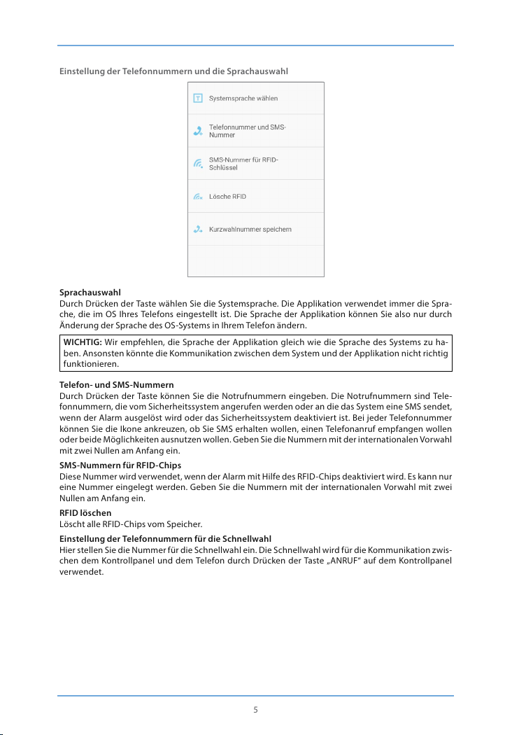
Einstellung der Telefonnummern und die Sprachauswahl
Sprachauswahl
Durch Drücken der Taste wählen Sie die Systemsprache. Die Applikation verwendet immer die Spra-
che, die im OS Ihres Telefons eingestellt ist. Die Sprache der Applikation können Sie also nur durch
Änderung der Sprache des OS-Systems in Ihrem Telefon ändern.
WICHTIG: Wir empfehlen, die Sprache der Applikation gleich wie die Sprache des Systems zu ha-
ben. Ansonsten könnte die Kommunikation zwischen dem System und der Applikation nicht richtig
funktionieren.
Telefon- und SMS-Nummern
Durch Drücken der Taste können Sie die Notrufnummern eingeben. Die Notrufnummern sind Tele-
fonnummern, die vom Sicherheitssystem angerufen werden oder an die das System eine SMS sendet,
wenn der Alarm ausgelöst wird oder das Sicherheitssystem deaktiviert ist. Bei jeder Telefonnummer
können Sie die Ikone ankreuzen, ob Sie SMS erhalten wollen, einen Telefonanruf empfangen wollen
oder beide Möglichkeiten ausnutzen wollen. Geben Sie die Nummern mit der internationalen Vorwahl
mit zwei Nullen am Anfang ein.
SMS-Nummern für RFID-Chips
Diese Num mer wird verwend et, wenn der Alarm mi t Hilfe des RFID- Chips deaktiv iert wird. Es ka nn nur
eine Nummer eingelegt werden. Geben Sie die Nummern mit der internationalen Vorwahl mit zwei
Nullen am Anfang ein.
RFID löschen
Löscht alle R FID-Chips vom Sp eicher.
Einstellung der Telefonnummern für die Schnellwahl
Hier stel len Sie die Nummer f ür die Schnellwah l ein. Die Schnell wahl wird für die Kom munikation zw is-
chen dem Kontrollpanel und dem Telefon durch Drücken der Taste „ANRUF“ auf dem Kontrollpanel
verwendet.
5
Page 31

Weitere Einstellungen
Änderung der Zonenbezeichnung
Das Sicher heitssyst em ermöglich t es, bis zu 9 versch iedene Sens oren zu bezei chnen. Die Ma ximallänge
einer Bezeichnung ist 30 Buchstaben. Die Bezeichnungen der Sensoren geben Sie ohne Diakritik ein.
Änderung der RFID-Bezeichnung des Schlüsselanhängers
Das Sicher ungssystem erm öglicht es, bis zu 4 ver schiedene RFID -Chips zu bene nnen. Die Bezeic hnun-
gen der RFID-Chips geben Sie ohne Diakritik ein. Wenn der Chip-Besitzer den Alarm deaktiviert, das
System sendet eine Textnachricht an die Telefonnummer, die Sie vorher gewählt haben.
WICHTIG: Die SMS-Abs endung einer SMS fun ktioniert nu r wenn der RFID- Chip benannt ist und e ine
Telefonnumm er des Administrato rs eingestellt ist, an die die SMS abges andt werden soll.
Einstellung einer Zeitverzögerung
Im Falle der Aktivierung und Deaktivierung kann bei dem Sicherheitssystem eine verzögerte Einschal-
tung eingestellt werden. Wenn die verzögerte Einschaltung eingestellt ist, gibt das Kontrollpanel jede
Sekunde einen Piepton aus. In den letzten 15 Sekunde wird die Frequenz der Pieptöne erhöht. Die
Maximallänge der Zeitverzögerung ist 300 Sekunden.
Lautst ärke der Sirene un d die Länge des Läu tens
Mit einem D ruck können Sie die Lautstärke und die Länge des Läute ns einstellen. Die L autstärke kann
in drei Stufen eingestellt werden, wobei das Kontrollpanel keinen Ton ausgibt, wenn das niedrigste
Lautstärkeniveau eingestellt ist. Die Maximallänge des Läutens ist 9 Minuten.
Verzögerung der Single-Zone
Im Falle der Aktivierung und Deaktivierung kann bei dem Sicherheitssystem eine verzögerte Einschal-
tung für den Einzelsensor eingestellt werden. Die Maximallänge der Zeitverzögerung ist 300 Sekun-
den.
Betätigung über SMS
Die Systemeinstellung kann durch Versand einer SMS geändert werden. Informationen über das
gesamte Angebot der SMS-Befehle rufen Sie durch Versand von einem, zwei oder drei Fragezeichen
auf, je nach der Gruppe, in der sich der Befehl bendet. Jeder Befehl hat seinen eigenen numerischen
Code.
?
- Deaktivierung - 0
- Aktivi erung - 1
6
Page 32

- Home- Modus - 2
- Zwei-Wege -Anruf - 3
- Sprachnachricht hinterlassen - 4
- Einstellungsanforderung - 00
??
- Telefonnumm er für den Warnanruf sp eichern - 5
- Telefonnumm er für die Warn-SMS speichern - 6
- Telefonnumm er für die SMS zum RFID-Chip speichern - 7
- Telefonnumm er für die Schnellwahl speichern - 8
???
- Zonenbe zeichnung - 91-99
- SMS-Bemerkung zu RFID -Chip - 10
- Einlegen und Löschen der verzögerten Einschaltung - 11
- Lautst ärke und Länge des Warnsignals - 12
- Deaktivierungspasswort - 13
- Verzögerte Einschaltung einer Einzelzone - 14
Sprachwechsel
Jede Sprache hat ihren vierstelligen Code. Sprache stellen Sie durch Absenden einer SMS mit diesem
vierstelligen Passwort an die Telefonnummer der SIM-Karte im Kontrollpanel ein. Nach Empfang der
Nachricht wird die Sprache gewechselt und das Kontrollpanel sendet eine SMS als Bestätigung über
den erfolgreichen Sprachwechsel zurück.
BEMERKUNG: Sprache könn en Sie auch über eine Applik ation einstellen.
Deakt ivierung des Ala rms mit Hilfe von SMS
Nach Absendung der SMS mit einem Fragezeichen erscheint auf dem Display eine Liste von Befehlen
mit numer ischen Codes. Dea ktivierung d es Alarms hat die Numm er „0“. Durch Absenden d ieses Codes
an die Telefonn ummer der SIM- Karte im Kontroll panel wird der Ala rm deaktivie rt. Nach einer er folgre-
ichen Deaktivierung sendet das Kontrollpanel eine Bestätigungs-SMS.
Aktivierung des Alar mes mit Hilfe eine r SMS
Die Aktivierung des Alarmes funktioniert in gleicher Weise wie die Deaktivierung. Der numerische
Code für di e Aktivierung is t die Nummer „1“. Durch Absenden di eses Codes an die Telefo nnummer der
SIM-Karte im Kontrollpanel wird der Alarm deaktiviert. Nach einer erfolgreichen Aktivierung sendet
das Kontrollpanel eine Bestätigungs-SMS.
Teilweise Ak tivierung des Alarms mit Hilfe e iner SMS (Home- Modus)
Teilweise Aktivierung des Alarms in den Home-Modus funk tioniert auf die gleiche Weise als die
gesamte Aktivierung. Der numerische Code für die Aktivierung ist die Nummer „2“. Durch Absenden
dieses Codes an die Telefonnummer der SIM-Karte im Kontrollpanel wird der Alarm deaktiviert. Nach
einer erfolgreichen Aktivierung sendet das Kontrollpanel eine Bestätigungs-SMS.
Beidseitige Kommunikation
Durch Absendung des numerischen Codes „3“ an die Telefonnummer der SIM-Karte im Kontrollpanel
bringen Sie ein Gesuch um beidseitige Kommunikation bei. Das System ruft sofort Ihre Telefonnu-
mmer zurü ck und Sie können so eine n gewöhnlichen Anruf machen.
Sprachnachricht hinterlassen
Durch Absendung des numerischen Codes „4“ an die Telefonnummer der SIM-Karte im Kontrollpanel
bringen Sie ein Gesuch um beidseitige Kommunikation bei. Das System ruft sofort Ihre Telefonnu-
mmer zurü ck. Nehmen Sie de n Anruf an und hinter lassen Sie eine Nac hricht, die maxim al 10 Sekunden
lang sein k ann. Die Nachricht k ann rückläug durch Drücken des RFID -Chiplesers a uf dem Kontrollpa-
nel abgespielt werden.
Betätigung des Systems während eines Notanrufs
Im Falle, dass der Alarm aktiviert ist, ruf t das Kontrollpanel die voreingestellten Nummern an. Folgen-
de Befehle können durch Drücken der entsprechenden Codes hervorgerufen werden.
7
Page 33

Befehl Der numerische Code
Deaktivierung 0
Aktivierung 1
Ausschalten des akustischen Warnsystems 6
Einschalten des akustischen Warnsystems 9
Zwei-Wege-Anruf *
Notnachricht abspielen #
Modus des Sicherheitssystems mit Hilfe einer SMS
Durch Abse ndung des numeri schen Codes „00 “ an die Telefonnummer d er SIM-Kar te im Kontrollpane l
bringen Sie ein Gesuch um eine Information über den Status des Sicherheitssystems.
Beispiel:
System ist aktiviert
- Verzögertes Ein- und Ausschalten: 0 Sekunden
- Verzögertes Ein- und Ausschalten der Einzelzone: 30 Sekunden
- Lautstärke des akustischen Warnsignals: 2
- Dauer des ak ustischen Warnsign als: 5 Minuten
- Passwor t für die Deaktivierung: 1234
Nottelefonnummer speichern
Die Notrufnummern sind Telefonnummern, die vom Sicherheitssystem angerufen werden, wenn der
Alarm ausgelöst wird oder das Sicherheitssystem deaktiviert ist. Wenn Sie die Liste der Notrufnu-
mmern ermitteln wollen, senden Sie den numerischen Code „5“ an die Telefonnummer der SIM-Karte
im Kontrollpanel ab.
Kopieren Sie den empfangenen SMS-Text und legen Sie den Text in die neue SMS. Nachfolgend füllen
Sie die Telefon nummern aus, die Si e als Notrufnumme rn haben wollen. W ir empfehlen, die Tele fonnu-
mmern mit den internationalen Vorwahlen einzugeben. Man kann mehrere Telefonnummern in die
Textnachricht einfügen und an die Telefonnummer der SIM-Karte im Kontrollpanel absenden.
Beispiel:
Die Information über die Notrufnummern kann folgendermaßen aussehen:
TEL:
1. 0 04 412345678 9
2. 004 41234567 89
3. 004 41234 5678 9
4. 004 41234 5678 9
5. 004 4123 456789
Nach Absendung der Information über neue Telefonnummern bestätigt Ihnen das Kontrollpanel den
Empfang und Änderung der Einstellungen.
WICHTIG: Änderungen im System können nur von gespeicherten Telefonnummern durchgeführt
werden.
Speichern der Notrufnummer für SMS
Die Notrufnummern für SMS sind Telefonnummern, an die das System eine SMS sendet, wenn ein
Alarm ausgelöst wird oder das Sicherheitssystem deaktiviert ist. Wenn Sie die Liste der Notrufnu-
mmern für SMS ermitteln wollen, senden Sie den numerischen Code „6“ an die Telefonnummer der
SIM-K arte im Kontrollpanel ab.
Kopieren Sie den empfangenen SMS-Text und legen Sie den Text in die neue SMS. Nachfolgend füllen
Sie die Telefon nummern aus, die Si e als Notrufnumme rn haben wollen. W ir empfehlen, die Tele fonnu-
mmern mit den internationalen Vorwahlen einzugeben. Man kann mehrere Telefonnummern in die
Textnachricht einfügen und an die Telefonnummer der SIM-Karte im Kontrollpanel absenden.
8
Page 34

Speichern der SMS-Nummer für RFID-Chips
Diese Nummer wird verwendet, wenn der Alarm mit Hilfe des RFID-Chips deaktiviert ist. Wenn Sie die
Notrufnummer ermitteln wollen, senden Sie den numerischen Code „7“ an die Telefonnummer der
SIM-K arte im Kontrollpanel ab.
Kopieren Sie den empfangenen SMS-Text und legen Sie den Text in die neue SMS. Nachfolgend füllen
Sie die Telefon nummern aus, die Sie a ls Notrufnumme rn für RFID-Ch ips haben wollen. W ir empfehlen,
die Telefonnummern mit der internationalen Vorwahl einzugeben. Senden Sie die SMS an die Telefon-
nummer der SIM-Karte im Kontrollpanel.
Speichern der Nummer für die Schnellwahl
Diese Nummer wird für die Schnellwahl verwendet. Die Schnellwahl können Sie durch Drücken der
Taste mit dem abgenommenen Telefonhörer hervorrufen. Wenn Sie die Telefonnummer ermitteln wo-
llen, senden Sie den numerischen Code „8“ an die Telefonnummer der SIM-Karte im Kontrollpanel ab.
Kopieren Sie den empfangenen SMS-Text und legen Sie den Text in die neue SMS. Nachfolgend füllen
Sie die Telefonnummern aus, die Sie als Nummern für die Schnellwahl haben wollen. Wir empfehlen,
die Telefonnummern mit der internationalen Vorwahl einzugeben. Senden Sie die SMS an die Telefon-
nummer der SIM-Karte im Kontrollpanel.
Änderung der Sensorbezeichnung
Jeder Sensor kann benannt werden. Die ersten neun Sensoren (1-9) können nach Ihren Propositionen
in einer Gesamtlänge von maximal 30 Zeichen geändert werden. Die Bezeichnungen der Sensoren 10
und höher können nicht geändert werden. Wenn Sie die Bezeichnung des Sensors ermitteln wollen,
senden Sie den numerischen Code „91“-„99“ an die Telefonnummer der SIM-Karte im Kontrollpanel ab.
Kopieren Sie den empfangenen SMS-Text und legen Sie den Text in die neue SMS. Nachfolgend füllen
Sie die Bezeichnung des Sensors aus und senden Sie diese an die Telefonnummer der SIM-Karte im
Kontrollpanel zurück.
Benennung des RFID-Chips
RFID-Chips können benannt werden. Wenn der Chip-Inhaber den Alarm deaktiviert, das System sen-
det eine Textnachricht an die Telef onnummer, die sie vorher gewählt haben.
WICHTIG: Die SMS-Absendung funk tioniert nur im Fall, dass der Chip benannt ist und eine Telefon-
nummer des Administrators eingestellt is t, an die die SMS abgesa ndt werden soll.
Änderung der Bezeichnung des RFID-Chips
Jeder RFID-Chip kann benannt werden. Wenn Sie die Bezeichnung des Chips ermitteln wollen, senden
Sie den nume rischen Code „10“ an die Telefonnu mmer der SIM-Ka rte im Kontrollpanel ab.
Kopieren Sie den empfangenen SMS-Text und legen Sie den Text in die neue SMS. Nachfolgend füllen
Sie die Bez eichnungen der Chi ps. Man kann mehrer e Namen in die Textnach richt einfügen un d zurück
an die Telefonnummer der SIM-Karte im Kontrollpanel absenden.
Beispiel:
Die Information über die Bezeichnungen der Einzelchips kann folgendermaßen aussehen:
Ändern Sie die Bezeichnung des RFID-Ch ips:
1. Vat i
2. Mutti
3. Thomas
4. Sara
Änderung der verzögerten Einschaltung
Im Falle der Aktivierung und Deaktivierung kann bei dem Sicherheitssystem eine verzögerte Einschal-
tung eingestellt werden. Wenn die verzögerte Einschaltung eingestellt ist, gibt das Kontrollpanel jede
Sekunde einen Piepton aus. In den letzten 15 Sekunde wird die Frequenz der Pieptöne erhöht. Wenn
Sie die Länge der verzögerten Einschaltung ermitteln wollen, senden Sie den numerischen Code „11“
an die Telefonn ummer der SIM-K arte im Kontrollpanel ab.
9
Page 35

Kopieren Sie den empfangenen SMS-Text und legen Sie den Text in die neue SMS. Nachfolgend stel-
len Sie die Länge der verzögerten Einschaltung ein und senden Sie diese an die Telefonnummer der
SIM-Karte im Kontrollpanel zurück. Die Maximalläge der verzögerten Einschaltung ist 300 Sekunden.
Einstel lung der Länge un d Lautstärke des A larms
Wenn Sie die Länge und Lautstärke des Alarms ermitteln wollen, senden Sie den numerischen Code
„12“ an die Telefonnummer der SIM-Kar te im Kontrollpanel ab.
Kopieren Sie den empfangenen SMS-Text und legen Sie den Text in die neue SMS. Nachfolgend stellen
Sie die Län ge und Lautst ärke des Alarms ei n und senden Sie di ese an die Telefonnum mer der SIM-K arte
im Kontrollpanel zurück.
Passwortänderung für die Deaktivierung des Alarms
Wenn Sie das Passwort für die Deaktivierung des Alarmes ermitteln wollen, senden Sie den numeris-
chen Code „13“ an die Telefonnummer der SIM- Karte im Kontrollpanel ab.
Kopieren Sie den empfangenen SMS-Text und legen Sie den Text in eine neue SMS. Nachfolgend stel-
len Sie das ne ue Passwort für d ie Deaktivier ung des Alarms ein un d senden Sie diese a n die Telefonnu-
mmer der SIM-Karte im Ko ntrollpanel zurü ck.
Einstellung des verzögerten Ein- und Ausschalten der Einzelzone
Im Falle der Aktivierung und Deaktivierung kann bei dem Sicherheitssystem die verzögerte Einschal-
tung für die Einzelzone eingestellt werden. Wenn Sie die Länge der verzögerten Einschaltung der Ein-
zelzone ermitteln wollen, senden Sie den numerischen Code „14“ an die Telefonnummer der SIM-Karte
im Kontrollpanel ab.
Kopieren Sie den empfangenen SMS-Text und legen Sie den Text in die neue SMS. Nachfolgend stel-
len Sie die Länge der verzögerten Einschaltung ein und senden Sie diese an die Telefonnummer der
SIM-Karte im Kontrollpanel zurück. Die Maximalläge der verzögerten Einschaltung ist 300 Sekunden.
Löschen der Sensoren, RFID-Chips und der Fernbedienungen aus dem System
Sämtliches Zubehör (Sensoren, RFID-Chips und Fernbedienungen) können durch dreifaches Drücken
des Schutzschalters an der Rückseite des Kontrollpanels in drei Sekunden ausgeschaltet werden. Das
Kontrollp anel gibt zwei Piep töne aus, wenn das Zubehör gelöscht ist .
Löschen der Sensoren aus dem System
Der numer ische Code für das Löschen der Sensoren aus dem System ist „ 21“. Durch Absendung di eses
Codes an die Telefonnummer der SIM-Karte im Kontrollpanel werden die Sensoren aus dem System
gelöscht. Nach einer erfolgreichen Aktivierung sendet das Kontrollpanel eine Bestätigungs-SMS.
Löschen d er RFID-Chip s aus dem System
Der numerische Code für das Löschen der RFIF- Chips aus dem System ist „22“. Durch Absendung die-
ses Codes an d ie Telefonnummer der SIM-Karte im Kontrollpanel werden di e RFID-Chips aus dem Sys-
tem gelöscht. Nach einer erfolgreichen Aktivierung sendet das Kontrollpanel eine Bestätigungs-SMS.
Löschen der Fernbedienungen aus dem System
Der numerische Code für das Löschen der Fernbedienungen aus dem System ist „21“. Durch Absen-
dung dieses Codes an die Telefonnummer der SIM-Karte im Kontrollpanel werden die Fernbedienun-
gen aus dem System gelöscht. Nach einer erfolgreichen Aktivierung sendet das Kontrollpanel eine
Bestätigungs-SMS.
Rückstellung des Systems in die Fabrikeinstellungen
Der numer ische Code für di e Rückstellun g des Systems in die Fabri keinstellunge n ist „0000“. Durc h Ab-
sendung dieses Codes an die Telefonnummer der SIM-Karte im Kontrollpanel wird das System wieder
in die ursprüngliche Einstellung gebracht. Nach einem erfolgreichen Reset sendet das Kontrollpanel
eine Bestätigungs-SMS.
Weitere SMS-Hinweise
Diese Hinweise werden an die als erste gespeicherte Telefonnummer für Hinweise gesendet. Sie ma-
chen aufmerksam:
- Beim niedrigen Batteriestand im Kontrollpanel oder in den Sensoren
10
Page 36

- Falls der Energieanschluss zu de m Kontrollpanel kollabiert
- Wenn der Schutzschalter an den Sensoren oder dem Kontrollpanel aktiviert ist (die SMS erhalten alle
Telefonnummern).
Aktivierung und Deaktivierung mit einem Anruf kostenlos
Das Sicherheitssystem k ann durch einen Anruf an die Telefonnummer der SIM-Kar te im Kontrollpanel
aktiviert werden. Sobald Sie das Läuten kören, hängen Sie ab. Das Kontrollpanel ruft Sie an der glei-
chen Telefonnummer zurück. Dadurch ist der Alarm aktiviert.
Das Sicherheitssystem k ann durch einen Anruf an die Telefonnummer der SIM-Kar te im Kontrollpanel
deaktiviert werden. Halten Sie den Anruf, bis sich das System nicht selbst deak tiviert. Das Kontrollpa-
nel ruf t Sie nicht zurück, der Alarm ist dadurch deaktiviert.
WICHTIG: Bei der Aktivierung und Deaktivierung ist wichtig, die Sprachbox auf der SIM-Karte im
Kontrollpanel auszuschalten.
Fernbedienung
Produktabbildung
SOS
ENTSPERREN
DIODE
Aktivierung
Wenn Sie den Alarm aktivieren wollen, drücken Sie die Taste „SPERREN“ auf der Fernbedienung. Die
Diode an der Bedienung leuchtet auf und ein Piepton ertönt. So ist der Alarm aktiviert.
Deaktivierung
Wenn Sie den Alarm deaktivieren wollen, drücken Sie die Taste „ENTSPERREN“ auf der Fernbedienung.
Die Diode an der Bedienung leuchtet auf und ein doppelter Piepton ertönt. So ist der Alarm deakti-
viert.
Home-Modus
Wenn Sie den Home-Modus aktivieren wollen, drücken Sie die Taste „HOME“ auf der Fernbedienung.
Alle Sensoren in der Normalgruppe werden aktiviert. Alle Sensoren in der Home-Gruppe werden nicht
aktiviert. Ihr Zuhaus e ist dadurch teilweis e gesichert.
Stiller Modus
Wenn Sie den stillen Modus aktivieren wollen, halten Sie die Taste „HOME“ an der Fernbedienung für
eine Sekunde gedrückt und dann drücken Sie die Taste „SPERREN/ENTSPERREN“ für drei Sekunden.
Das Sicherheitssystem ist aktiviert/deaktiviert ohne irgendwelche Töne. Das Sicherheitssystem kann
also betätigt werden, ohn e die Nachbarn zu stören.
Notruf
Durch Drücken der Taste SOS an der Fernbedienung wird sofort der Alarm ausgelöst, ungeachtet, ob
das Sicherheitssystem aktiviert oder deaktiviert ist.
Anschluss der Fernbedienung
Wollen Sie die Fernbedienung koppeln, geben Sie das Passwort ins Kontrollpanel ein und drücken Sie
HOME
SPERREN
11
Page 37

die Taste „AUFNAH ME“. Die Taste leuchte t auf. Danach drücken Sie e ine beliebige Taste an de r Fernbe-
dienung und ein Piepton ertönt. Die Fernbedienung ist dadurch gekoppelt. Wenn Sie an dem Kontro-
llpanel einen doppelten Piepton hören, wurde die Bedienung schon vorher gekoppelt.
RFID-Chips
RFID-Chips werden für die Deaktivierung des Sicherheitssystems verwendet. Das System kann man
durch Zulegen zum RFID-Chipleser deaktivieren.
Anschluss der neuen RFID-Chips
Wollen Sie ne ue RFID-Chi ps koppeln, gebe n Sie das Passwort i ns Kontrollpanel e in und drücken Sie di e
Taste „AUFNAHME“. Die Taste leuchtet auf. Jetzt halten Sie die RFID -Chips in der Nähe des RFID- Chi-
plesers auf dem Kontrollpanel. Sobald Sie einen Piepton hören, ist der RFID-Chip gekoppelt. Wenn Sie
an dem Kontrollpanel einen doppelten Piepton hören, wurde die Bedienung schon vorher gekoppelt.
WICHTIG: RFID-Chips funktionieren nur wenn das Kontrollpanel zum elektrischen Spannung an-
geschlossen ist.
Sensoren
Das Warnsystem ist am eektivsten, wenn die Sensoren gut aufgestellt sind. Bestimmen Sie, welche
Stellen Sie kontrollieren können und dort stellen Sie die Sensoren auf. Wir empfehlen, das Kontro-
llpanel in der Nähe der Eingangstür aufzustellen. Der Magnetdetektor ist bestimmt für Befestigung
an Fenster, Türen oder Terrassentüren. Platzieren Sie den Sensor bestenfalls in eine Ecke des Raumes,
damit der Sensor einen Überblick über den ganzen Raum hat. Platzieren Sie den Rauchdetektor auf die
Decke des R aumes und den Wasserd etektor ins Bade zimmer, bzw. in die Küche na he des Spülbeckens ,
Waschbeckens oder der Badewanne.
PIR-Bewegungssensor
PIR senzor pohybu dokáže rozeznat malá domácí zvířata, a ty tak nespustí alarm v době, kdy nejste
doma a máte bezpečnostní s ystém aktivován .
Produktabbildung
Detektions-fenster
1. Detektionsfenster
2. Diode
3. Wandhalter
Diode
12
Page 38

Diode
Fortlaufendes Blinken: der Bewegungssensor führt ein Auto-Test durch
Einmaliges Blinken: Bewegung detektiert
Doppeltes Blinken: Drei-Minuten-Testen ist beendet, der Sensor schaltet in den Sparmodus um
Blinken alle 3 Sekunden: Hinweis auf entladene Batterie
BEMERKUNG: Wenn die Batterie entla den ist, sendet das Gerät einen SMS-Hinweis.
Produktabbildung innen
Diode
Infraroter Sensor
Schutzschalter
Infraroter Sensor
Moduseinstellungen
Entfernen Sie vorsichtig das Gehäuse von der Rückseite des Sensors.
Infrarote Sensoren
Infrarote Sensoren detektieren die Bewegung. Halten Sie die Sensoren daher sauber. Berühren Sie die
Sensoren nicht.
Schutzschalter
Wenn Sie das Gehäuse des PIR-Bewegungssensors önen, sendet der Schutzschalter ein Signal ins
Kontrollpanel.
Diode
Die Diode auf der Vorderseite des PIR-Bewegungssensors kann durch Versetzung der Überbrückung
ein- oder ausgeschaltet werden.
Rückseite des PIR-Bewegungssensors
Tes tmo dus
Durch Drücken der Prüftaste nach Beenden des Auto-Tests sendet der PIR-Bewegungssensor ein
Signal ins Kontrollpanel (die D iode blinkt).
Sparmodus
PIR-Bewegungssensor schaltet automatisch in den Sparmodus um, wenn er eine Bewegung zwei-
mal in drei Minuten vermerkt. Wenn der Sensor in weiteren drei Minuten eine Bewegung vermerkt,
schaltet er zurück in den Arbeitsmodus um. Während dieser drei Minuten darf der Sensor nicht akti-
viert werden und sendet dem Kontrollpanel kein Signal ab. Im Falle, dass der Sensor eine Bewegung
während dieser drei Minuten detektiert, verlängert sich der Sparmodus um weitere drei Minuten.
Anschluss des PIR-Bewegungssensors
WICHTIG: Im Falle, dass Sie den PIR-Bewegungssensor koppeln, sorgen Sie dafür, dass keine andere
Sensoren das Ereignis aufnehmen. Decken Sie also die Sensoren oder tragen Sie die Sensoren kur-
zzeitig in einen Raum, wo keine Bewegung ist. Die Sensoren, die im Lieferumfang enthalten sind,
sind standardmäßig mit dem Kontrollpanel gekoppelt.
13
Page 39

Wollen Sie den PIR-Sensor der Bewegung koppeln, geben Sie das Passwort ins Kontrollpanel ein und
drücken Sie die Taste „AUFNAHME“. Die Taste leuchtet auf. Drücken Sie die Prüftaste an der Rückseite
des Sensors zweimal. Sobald Sie einen Piepton hören, ist der PIR-Sensor gekoppelt. Wenn Sie an dem
Kontrollpanel einen doppelten Piepton hören, wurde die Bedienung schon vorher gekoppelt.
Installation des PIR-Bewegungssensors
Install ieren Sie den Se nsor nicht dire kt an Fenster, in de r Nähe von Klim aanlagen, He izung, Kühlsc hrank,
Backro hr, in direk tes Sonnenlicht un d an Stellen, wo sich die Temper atur oft änder t. Vermeiden Sie die
Installierung von zwei Sensoren gegenüber und in die Reichweite des Sensors.
BEMERKUNG: Ideale Höhe für die Installation des Sensors ist 2,2 m.
Befestigen Sie den Sensorhalter mit Schrauben, die im Lieferumfang enthalten sind. Schieben Sie dann
den Sensor in den Halter ein. Stellen Sie die richtige Richtung des Sensors, damit er die gewünschte
Fläche deckt. Überprüfen Sie die Funktion des Sensors durch Überschaltung in den Testmodus.
WICHTIG: Wenn Sie die Funktion der Tiererkennung verwenden, bewegen Sie den Sensor nicht nach
oben und unten.
Testen des PIR-Bewegungssensors
1. Sobald der Bewegungssensor installiert und aktiviert ist, können Sie es prüfen. Drücken Sie einmal
die Prüf taste und gehen Sie im Raum von links nac h rechts und von recht s nach links.
2. Sobald der Sensor eine Bewegung vermerkt, blinkt die Diode einmal.
3. Richten Sie den Einstellungswinkel des Sensors ein, wenn es nötig ist. Wiederholen Sie diesen Vor-
gang, bis Sie den gewünschten Ergebnis reichen.
Magnetsensor
Produktabbildung
Sensor
Magnet
Diode
Einmaliges Blinken: Önen der Tür/des Fensters detektiert
Blinken alle 3 Sekunden: Hinweis auf entladene Batterie
BEMERKUNG: Wenn die Batterie entla den ist, sendet das Gerät einen SMS-Hinweis.
14
Page 40

Produktabbildung innen
Schutzschalter
Moduseinstellungen
Schutzschalter
Im Falle, dass Sie das Gehäuse des Magnetsensors önen, sendet der Schutzschalter ein Signal ins
Kontrollpanel ab.
Installationstipps
Installation des Magnetsensors
Der Magnetsensor kann an Fenster, Türen oder andere Objekte installiert werden, die man önen und
schließen kann. Der Sensor besteht aus zwei Teilen, der größere Teil ist der Sensor, der kleinere Teil
ist der Magnet mit dem Fühler. Befestigen Sie den Sensor auf den Rahmen und den Magnet auf den
beweglichen Teil.
Die Diode auf dem richtig installierten Magnetsensor blinkt einmal, wenn beide Teile um mehr als 1
cm getrennt werden. Die Entfernung der beiden Teile im geschlossenen Zustand darf also nicht größer
als 1 cm sein.
Befestigen Sie beide Teile des Magnetsensors mit einem beidseitigen Klebeband oder mit Schrauben.
Wir empfehlen nicht, den Magnethalter auf eine Metalloberäche oder auf Stellen mit vielen Metall-
teilen zu installieren. Kontrollieren Sie, ob die Diode blink t, wenn das Fenster oder die Tür geönet
werden.
WICHTIG: Auf beiden Teilen d es Magnethalter s ist ein Pfeil abg ebildet. Die Teile müs sen so befestig t
werden, dass die Pfeile aufeinander gerichtet sind.
Anschluss des Magnethalters
1. Vergewissern Sie sich, dass der Sensor neben dem Magnet in einer Entfernug von weniger als 1 cm
befestigt ist.
2. Geben S ie das Passwort ins Kontrollpanel ein u nd drücken Sie die Taste „AUFNAHME“.
3. Die Taste für Auf nahme leuchtet auf.
4. Trennen Sie die beide Teile auf eine Ent fernung von mehr als 1 cm voneinander.
5. Der Sensor vermerkt das Ereignis. Das Kontrollpanel piept einmal, wenn der Sensor erfolgreich ge-
koppelt ist. Wenn Sie an dem Kontrollpanel einen doppelten Piepton hören, wurde die Bedienung
schon vorher gekoppelt.
Ausgang des Elektroschlosses
Das Konnektor PUSH und GND des Elektroschlosses kann an das Konnektor PUSH und GND auf der
Rückseite des Kontrollpanels angeschlossen werden.
Sobald Sie das Sicherheitssystem deaktivieren, das mit dem Elektroschloss verbunden ist, das Kontro-
llpanel s endet ein Signal ins El ektroschloss und dieser wird automatisch entsper rt.
BEMERKUNG: Die Tür mit einem Elektroschloss wird beim Ausfall der Stromversorgung automatisch ent-
sperrt. Wir empfehlen ausdrücklich, eine Netzersatzanlage anzuschließen.
15
Page 41

Installation des Kontrollpanels
Das Kontrollpanel kann direkt an die Wand oder mit Hilfe eines Gestells auf jede waagrechte Oberä-
che befestigt werden. Sämtliches Zubehör ist im Lieferumfang enthalten.
Wandinstallation
Das Kontrollpanel wird mit Hilfe des Halters und der Schrauben an die Wand befestigt, die im Liefe-
rumfang e nthalten sind. Schi eben Sie das Kontro llpanel in den Halte r von oben nach unten . Der Halter
sichert, dass der Schutzschalter immer gedrückt ist.
Installation auf eine waagrechte Oberäche
Mit Hilfe d es Gestells können Si e das Kontrollpanel auf jede waagrechte Oberäche befestigt werden.
Schieben Sie das Gestell in das Kontrollpanel von oben nach unten ein. Das Gestell sichert, dass der
Schutzschalter immer gedrückt ist.
WICHTIG: Drücken Sie den Schutzsch alter mehrmals. Das b ewirkt einen Systemreset.
Einstellung der Sensoren in Modi
Jeder Sensor kann in einen der vier möglichen Modi eingeordnet werden. Das Sicherheitssystem er-
kennt den Homemodus, den Normalmodus, 24-Stunden-Modus und den Modus für die Einzelzone.
WICHTIG: Bevor Sie das Sicherheitssystem einstellen, entscheiden Sie sich, welchen Sensor Sie in
welche Gruppe einordnen. Wenn Sie Sensorgruppe wechseln möchten, müssen Sie den Sensor vom
Kontrollpanel abschalten.
Die unten angeführte Abbildungen stellen die Switch-Einstellungen in den Sensoren für Einzelgrup-
pen dar.
Normalmodus Home-Modus Modus fürdie Einzelgruppe 24-Stunden-Modus
Normalmodus
Die gelieferten Magnetdetektoren, die im Lieferumfang enthalten sind, sind standardmäßig im Nor-
malmodus. Sie sind als D0, D1 und D2 eing estellt. Im Normalmodus sind die Se nsoren immer akt iviert,
wenn der Alarm aktiviert ist.
Home-Modus
Der gelieferte Bewegungssensor, der im Lieferumfang enthalten ist, ist standardmäßig im Normalmo-
dus. Die Be wegungssensor en sind als D0 und D1 einges tellt. Wenn der Hom e-Modus ein gestellt ist, im
Falle einer Störung senden die Sensoren in dieser Gruppe ein Signal ins Kontrollpanel ab, der Alarm
wird aber nicht ausgelöst. Im Normalmodus senden die Sensoren im Falle einer Störung ein Signal ins
Kontrollpanel und der Alarm wird ausgelöst. Der Home-Modus ermöglicht es, den Haushalt teilweise
abzusiche rn und gleichzeiti g sich frei im Haus oder i n der Wohnung zu bewege n.
Modus für die Einzelgruppe
Die Detektoren können auf verzögerte Einschaltung eingestellt werden, einzeln oder als Gruppe. Die
angeführte Einstellung wird gewöhnlich für Magnetdetektoren der Türen oder Fenster verwendet.
Wenn z.B. d er Benutzer die Fer nbedienung nicht b ei sich führt, hat er nach dem Önen der Tür genug
Zeit für die Deaktivier ung des Alarms, bevor der Warnsignal ausgelöst wird.
24-Stunden-Modus
Einstellung der Sensoren in den 24-Stunden-Modus wird z.B. beim Rauchdetektor als Standardeinste-
16
Page 42

llung empfohlen. Wenn sich der Sensor im 24-Stunden-Modus bendet, ist er aktiv und wenn es nötig
ist, sendet er das Signal ins Ko ntrollpanel, ungeachtet ob das System aktiv ist oder nicht.
Änderung der Sensorbezeichnung
Gelieferte Bewegungsdetektoren und Magnetdetektoren sind mit dem System gekoppelt. Jeder Sen-
sor ist num eriert, je nach d em, in welcher Fol ge er gekoppelt wu rde (Zone 1 - Zone 9). Die Be zeichnun-
gen der einzelnen Senzoren können nachfolgend geändert werden.
Tes tmo dus
Das System ka nn in den Testmodus ein gestellt werde n. Wenn es zu einem Erei gnis kommt gibt das Sys-
tem in diese m Modus drei Pieptön e aus, anstatt eine s lauten akustische n Warnsignals. Der Testmo dus
wird eing eschaltet, wenn Sie d ie Taste „ENT SPERREN“ dreimal hin tereinander drüc ken. Der Testmodus
ist akti viert, wenn da s Kontrollpanel e inen Piepton ausg ibt. Nach 10 Minuten sc haltet das System aut o-
matisch vom Testmodus um. Der Testmodus kann manuell ausgeschaltet werden, wenn Sie die Taste
„SPERREN“ drücken.
Technische Parameter
Kontrollpanel
Stromversorgung 12V DC 500 mA
Netzfrequenz 850/900/180 0/1900 MHz
Strom im Bereitschaftsmodus 110 mA
Strom bei Alarmaktivierung 340 mA
Reichweite der Sensoren vom Kontrollpanel Bis 80 m (im Frei raum)
Reservebatterie Li-Ion -Batterie 3,7 V 800 mA, BL-5B (2x)
Eingebaute Sirene 95 dB
Maximalmenge des angeschlossenen
Zubehörs
Radiofrequenz 315 MHz oder 433,92 MHz
Material ABS-Kunststo + Acryl-Kunststo
Betriebstemperatur -10 bis +50° C
Betriebsfeuchtigkeit Bis 80 % (nicht kondensiert)
Abmessungen 188 x 132 x 26 mm
PIR-Bewegungssensor
Stromversorgung 3V DC (2 x AA 1,5V LR6)
Strom im Bereitschaftsmodus 90 uA
Strom bei der Alarmaktivierung 9,5 mA
Reichweite des Sensors bis 8 m / 110°
Erkennung der Tiere ca. b is 25 kg
Reichweite des Sensors von dem Kontrollpanel Bis 80 m (im Frei raum)
Radiofrequenz 315 MHz oder 433,9 MHz
Material ABS-Kunsts to
Betriebstemperatur -10 bis +50° C
Betriebsfeuchtigkeit Bis 80% (nicht kondensiert)
Abmessungen des Sensors 108 x 52 x 36,8 mm
Abmessungen des Halters 52 x 30 x 26,5 mm
Magnethalter
Stromversorgung 1,5V DC (1 x AA 1,5V LR6)
Strom im Bereitschaftsmodus 35 uA
Strom bei der Alarmaktivierung 10 mA
Reichweite des Sensors von dem Kontrollpanel Bis 80 m (im Freir aum)
10x Fernbedienung
50x Sensor
50x RFID -Chip
17
Page 43

Radiofrequenz 315 MHz nebo 433,92 MHz
Material ABS-Kunsts to
Betriebstemperatur -10 až +50° C
Betriebsfeuchtigkeit Bis 80% (nicht kondensiert)
Abmessungen des Sensors 71 x 34 x 17,5 mm
Abmessungen des Magnets 51 x 12 x 13,5 mm
Fernbedienung
Stromversorgung DC 3V
Strom 7 mA
Reichweite der Bedienung von dem
Kontrollpanel
Radiofrequenz 315 MHz oder 433,9 MHz
Material ABS + PC -Kuns tsto
Betriebstemperatur -10 bis +50° C
Betriebsfeuchtigkeit Bis 80% (nicht kondensiert)
Abmessungen 58 x 31 x 9,5 mm
Bis 80 m (im Frei raum)
RFID-Chip
Schaltkreis EM4100 CMOS
Radiofrequenz 125 KHz
Abmessungen 30 x 30 x 6 mm
Elektroerzeugnisse sollten nicht mit Restmüll beseitigt werden. Nach der europäischen Richtlinie
2002/96/EC über den Elektroabfal und über die Elektroausstattung und ihre Bestandteile müssen sie
gesondert in Sammelstellen abgegeben werden.
HINWEI S: Im Falle, dass Sie die Ba tterie im Gerät fü r einen unzulässi gen Batteriet yp tauschen, en t-
steht ein Risiko der Beschädigung oder Verbrennung. Verwenden Sie nur zulässige Batterietypen
gemäß den in den Tabellen angegebenen technischen Parametern.
Problemlösung
Im Falle, das das Sicherheitssystem Shield by LAMAX Tech nicht richtig funtioniert, versuchen Sie fol-
gende Lösungen vorzunehmen.
Das Kontrollpanel schaltet nicht ein.
- Vergewissern Sie sich, dass die Stromversorgung richtig angeschlossen ist.
- Vergewisse rn Sie sich, dass das Ger ät eingeschaltet is t.
Die Fernbedienung funktioniert nicht
- Kontrollieren Sie, ob die Diode beim Drücken der Taste des oenen Schlosses aueuchtet.
- Kontrollieren Sie , ob die Bedienung richtig mit dem Kontrollpanel gekoppelt ist.
- Vergewissern Sie sich, das die Entfernung zwischen der Fernbedienung und dem Kontrollpanel nicht
zu groß ist .
Der Magnetsensor funktioniert nicht
- Kontrollieren Sie, ob die Diode beim Önen/Schließen des Fensters aueuchtet.
- Vergewissern Sie sich, das die Entfernung zwischen der Fernbedienung und dem Kontrollpanel nicht
zu groß ist .
- Kontrollieren Sie, ob das Sicherhetssystem aktiviert ist.
- Kontrolli eren Sie, ob die Entfe rnung zwischen dem Sensor und dem M agnet kleiner als 1 c m ist.
Der PIR- Bewegungssens or vermerkt das E reignis, das Kont rollpanel löst a ber den Alarm nicht a us.
- Drücken Sie die Pr üftaste auf d em Sensor, wenn das Siche rheitssyst em aktivier t ist. Wenn das Kontro -
llpanel ke inen Alarm auslöst , koppeln Sie wieder das Kontrollpanel mit dem Sensor.
- Vergewissern Si e sich, das die Entfe rnung zwisch en dem Sensor und d em Kontrollpane l nicht zu groß ist.
- Ko ntrollieren Sie, ob sich der Sensor nicht im Sparmodus be ndet.
- Kontrollieren Sie, ob die Batterie nicht entladen ist.
18
Page 44

Das Kontro llpanel antwor tet auf die Befeh le mit Hilfe der SMS n icht.
- Ko ntrollieren Sie, ob die SIM-Kar te richtig eingefügt ist.
- Stellen Sie sicher, dass die SIM- Karte vor der System einstaltung eing elegt wurde.
- Kotrollie ren Sie, ob die SIM-K arte in Standard GSM ist.
- Kontrolli eren Sie, ob der Kredit der SIM-Karte aktivie rt ist.
- Kontrolli eren Sie, ob die SMS und Anr ufe an der SIM-Ka rte aktivier t sind.
Wenn der Ala rm ausgelöst wir d, bekommen Sie kei ne SMS.
- Kontrollieren Sie, ob die Notrufnummer in den Speicher des Kontrollpanels gespeichert wurde.
- Im Falle, dass der Alarm ausgelöst ist, deaktivieren Sie ihn nicht sofort, sonst wird der Anruf unter-
brochen.
- Ko ntrollieren Sie, ob d er Kredit der SIM- Karte aktiviert ist.
Das Siche rheitssystem l öst den Alarm aus, g ibt aber keinen Ton aus.
- Kontrollieren Sie, ob der Schall auf dem Kontrollpanel nicht gesenkt ist. Stellen Sie den akustischen
Warnsignal m it Hilfe der SMS oder Ap plikation neu ein.
Die Gebr auchsdauer der B atterie im Magne tsensor
- Der Magnet ist duch eine AA-Batterie versorgt, die eine Gebrauchsdauer von ca. 8-12 Monate hat. Es
hängt von der Frequenz des Kommens und Gehens ab.
Die Gebrauchsdauer der Batterie im PIR-Bewegungssensor
- Der Sensor ist d uch zwei AA-B atterien vers orgt, die eine Geb rauchsdauer von c a. 8-12 Monate hab en.
Es hängt von der Frequenz des Kommens und Gehens ab.
Das Kontro llpanel reagie rt auf den RFID- Chip nicht.
- D as Kontrollpanel rea giert auf den RFID -Chip, nur wenn es ins Stromnetz angeschlossen ist .
- Kontrolli eren Sie, ob der RFID -Chip mit dem Kontro llpanel gekoppe lt ist. Wenn nicht, kopp eln Sie es.
Das Kontro llpanel sendet keine SMS nach der A ktivierung/ Deaktivierung über den RFID -Chip.
- Ko ntrollieren Sie, ob die Notrufnummer und der Name des R FID-Chips gesp eichert ist.
Der Sensor, die Fernbedienung und weiteres Zubehör reagieren nicht, nachdem Sie das Kontro-
llpanel verschoben haben.
- Drücken Sie den Schutzschalter auf der Rückseite des Kontrollpanels dreimal hintereinander in drei
Sekunden. Sämtliche Verbindungen zwischen dem Kontrollpanel und dem Zubehör werden gelöst.
Vergewisse rn Sie sich, dass Sie den Al arm während der Inst allation des Kontrollpanels durch mehrfa-
ches Drücken nicht aktivieren.
Sie haben eine SMS erhalten, dass die Telefonnummer nicht autorisiert ist.
- Die SIM-Karte ist auf die Anzeige des Anrufenden eingestellt
- D ie Telefonnummer ist als die Notrufnummer des Alarms eingestellt.
Die Diod e des GSM-Netzes blinkt.
- Wenn die Diode des GSM-Netzes einmal pro Sekunde blinkt, das Netz wird ausgesucht. Wenn die
Diode des GSM-Netze s einmal in zwei Seku nden blinkt, das N etz wurde gefunden.
Der Bewegungssensor arbeitet nicht richtig.
- Wenn der PIR-Bew egungssensor ei n Ergeignis zweim al in drei Minuten ver merkt, schalt et er automa-
tisch in den S parmodus. Wenn d er Sensor in weite ren drei Minuten e ine Bewegung ver merkt, scha ltet
er zürück in den Normalmodus um. Während dieser drei Minuten ist der Sensor nicht aktiv und sen-
det kein Signal ins Kontrollpanel ab. Wenn während weiteren drei Minu ten eine Bewegung ver merkt
wird, der Sparmodus wird verlängert.
Exklu siver Einführer d er LAMAX Produkte für die EU:
elem6 s. r.o., Braškovská 308/15, 16100 Prag 6
http://www.lamax-electronics.com.
Druckfehler und Änderungen in der Betriebsanleitung sind vorbehalten.
19
Page 45

Shield by
UŽIVATELSKÁ PŘÍRUČKA
Page 46

OBSAH
Princip fungování systému �������������������������������������������������������������������������������������������������������������������������2
Ovládání bezpečnostního systému �����������������������������������������������������������������������������������������������������������3
Ovládání kontrolního panelu ............................................................................................................................................3
Aktivace systému (Normální skupina) .......................................................................................................................................3
Částečná aktivace systému (Domácí skupina) .......................................................................................................................3
Deaktivace systému na kontrolním panelu ............................................................................................................................3
Deakt ivace systému po mocí RFID čipu .................................................................................................................................... 3
Nahrávání a přehrávání hlasové zprávy ...................................................................................................................................3
Rychlá vo lba .........................................................................................................................................................................................3
Telefonní hovor ...................................................................................................................................................................................3
Nahrávání zprávy nouzového hovoru .......................................................................................................................................3
Uvedení systému do továrního nastavení ...............................................................................................................................3
Ovládá ní pomocí apli kace pro Androi d a iOS ...............................................................................................................4
Vytvoření účtu .................................................................................................................................................................................... 4
Nastavení bezpečnostního systému pomocí aplikace ......................................................................................................4
Ovládání přes SMS ...............................................................................................................................................................6
Změna jazyku ......................................................................................................................................................................................7
Deaktivace alarmu pomocí SMS ..................................................................................................................................................7
Aktivace alarmu pomocí SMS .......................................................................................................................................................7
Částečná aktivace alarmu pomocí SMS (Domácí mód) .....................................................................................................7
Oboustranná komunikace ............................................................................................................................................................. 7
Zanechání zprávy .............................................................................................................................................................................. 7
Ovládání systému během nouzového volání ........................................................................................................................7
Status bezpečnostního systému pomocí SMS ......................................................................................................................8
Uložení nouzového telefonního čísla ........................................................................................................................................8
Uložení nouzového telefonního čísla pro SMS ......................................................................................................................8
Uložení SMS čísla pro RFID čipy....................................................................................................................................................8
Uložení čísla pro rychlou volbu ....................................................................................................................................................8
Změna názvu senzoru......................................................................................................................................................................9
Pojmenování RFID čipu ...................................................................................................................................................................9
Změna náz vu RFID čipu ................................................................................................................................................................... 9
Změna zpožděného zapnutí .........................................................................................................................................................9
Nastave ní délky a hlasito sti alarmu ............................................................................................................................................ 9
Změna hesla pro deaktivaci alarmu ...........................................................................................................................................9
Nastavení zpožděného vypnutí jednotlivé zóny ..................................................................................................................9
Smazán í senzorů, RFID čip ů a dálkových ovlád ání ze systému ....................................................................................10
Smazán í senzorů ze syst ému ......................................................................................................................................................10
Smazán í RFID čipů ze systém u ...................................................................................................................................................10
Smazán í dálkových ovlad ačů ze systému..............................................................................................................................10
Uvedení systému do továrního nastavení .............................................................................................................................10
Další SMS upozornění ....................................................................................................................................................................10
Aktivace a deaktivace telefonním hovorem zdarma ........................................................................................................10
Dálkové ovládání ����������������������������������������������������������������������������������������������������������������������������������������11
Nákres produktu .............................................................................................................................................................................. 11
Aktivace ...............................................................................................................................................................................................11
Deaktivace ..........................................................................................................................................................................................11
Domácí mód.......................................................................................................................................................................................11
Tichý mód............................................................................................................................................................................................ 11
Nouzové volání .................................................................................................................................................................................11
Připojení nového dálkového ovládání ....................................................................................................................................11
Page 47

RFID čip y ������������������������������������������������������������������������������������������������������������������������������������������������������11
Připoje ní nových RFID čipů .......................................................................................................................................................... 11
Senzory ��������������������������������������������������������������������������������������������������������������������������������������������������������12
PIR senzor pohybu .............................................................................................................................................................12
Nákres produktu ..............................................................................................................................................................................12
Dioda .....................................................................................................................................................................................................12
Nákres produktu zevnitř ...............................................................................................................................................................13
Infračervené senzory ......................................................................................................................................................................13
Ochranný spínač...............................................................................................................................................................................13
Dioda .....................................................................................................................................................................................................13
Testovací mód ...................................................................................................................................................................................13
Úsporný mód .....................................................................................................................................................................................13
Připojení PIR senzoru pohybu ....................................................................................................................................................13
Instalace PIR senzoru pohybu.....................................................................................................................................................13
Testování PIR senzoru pohybu ...................................................................................................................................................14
Magnetický senzor .............................................................................................................................................................14
Nákres produktu ..............................................................................................................................................................................14
Dioda .....................................................................................................................................................................................................14
Nákres produktu zevnitř ...............................................................................................................................................................14
Tipy pro instalaci ................................................................................................................................................................15
Instalace magnetického senzoru ..............................................................................................................................................15
Výstup elektrického zámku .........................................................................................................................................................15
Instalace kontrolního panelu ......................................................................................................................................................15
Sestavování senzorů do režimů ......................................................................................................................................15
Normální mód ...................................................................................................................................................................................16
Domácí mód.......................................................................................................................................................................................16
Mód pro jednotlivou skupinu .....................................................................................................................................................16
24 hodinov ý mód .............................................................................................................................................................................16
Změna pojmenování senzoru ....................................................................................................................................................16
Testovací mód ...................................................................................................................................................................................16
Technické parametry ���������������������������������������������������������������������������������������������������������������������������������17
Kontrolní panel ...................................................................................................................................................................17
PIR senzor pohybu .............................................................................................................................................................17
Magnetický držák ...............................................................................................................................................................17
Dálkový ovladač .................................................................................................................................................................18
RFID čip ................................................................................................................................................................................. 18
Řešení problémů�����������������������������������������������������������������������������������������������������������������������������������������18
Page 48

Nákres produktu
Dioda GSM s ítě
Stavová dio da
Tlačítko HOVORU Tlačítko ODEMKNOUT
Tlačítko DOMŮ
Čtěčka RFID č ipu Tlačítko ZAMKNOUT Tlačítko NAHRÁVÁNÍ
Reproduktor Ochranný spínač
Mikrofon
Mikrofon
1
Page 49

Princip fungování systému
V případě, že senzory zaznamenají událost, pošlou signál do kontrolního panelu. Stanice zapne zvu-
kový výstražný signál a o dešle SMS na všechna ul ožená telefonní čísla. V případě, že ne dojde k deakti-
vování alarmu, kontrolní panel uskuteční telefonní hovor na vše chna uložená telefonní čísla. Pokud je
připoje na externí siréna (vo litelně), spustí zvukový výstražný signál paralelně se stanicí.
ZAČÍNÁ ME:
Vložen í SIM karty
1. Ujistěte se, že je bezpečnost ní systém vypnu t.
2. DŮLEŽI TÉ: Trvale s mažte defaultní kód ze SIM karty.
3. Pokud je ak tivována funkce zá znamníku, vypněte ji.
4. Než vlož íte SIM kartu do slot u, vysuňte nejpr ve bezpečnostní pojistku slotu .
Slot pro SIM kartu
Drátové připojení senzorů
24 hodinového módu
Drátové připojení senzorů
normálního módu
Připojení elektrického zámku
Drátové připojení sirény
Připojení napájení
Hlavní vypínač
DŮLEŽITÉ: Bezpečn ostní systém pou žívá pro svůj provoz SM S zprávy. Jejich posí lání je zpoplatn ěno
dle platného tarifu Vašeho operátora. SMS používají aplikace Android i Apple.
Zapnutí kontrolního panelu
Zapojte napájecí kabel do konektoru v z adní části kontroln ího panelu. Poté odklopte zadní k ryt a pře-
pněte hlavní vypínač do p olohy ON.
Síťové připojení
Bezpe čnostní systém z ačne ihned, po z apnutí, vyh ledávat síťové přip ojení. Síťová dio da v takovém pří-
padě blik á jednou za v teřinu. Jakmil e se systém přip ojí do sítě, dioda s níží frekven ci blikání na 2 v teřiny.
POZNÁ MKA: Bliká-li dioda jednou za vteřinu, kontrolní panel není připojen do sítě. Zkontrolujte, zda je
bezpečnostní PIN SIM karty deaktivován.
2
Page 50

Ovládání bezpečnostního systému
Bezpečnostní systém je možné ovládat pomocí SMS, přes aplikaci pro Android nebo iOS či na kont-
rolním panelu.
DŮLEŽITÉ: Názv y účtů, senzorů, R FID čipů a dálkových ovladačů v ždy zadávejte bez diakritiky. Tele-
fonní čísla vždy zadávejte s m ezinárodní předvolbou s dvěma nulami místo +.
Příkla d: 0044 123 456 789
Ovládání kontrolního panelu
Aktivace systému (Normální skupina)
Stiskněte tlačítko „ZAMKNOUT“. Všechny senzory jsou aktivovány.
Částečná aktivace systému (Domácí skupina)
Stiskněte tlačítko „DOMŮ“. Senzory, které jsou nastaveny v Domácí skupině, nebudou aktivovány, po-
kud je na kontrolním panelu nastaven Domácí mó d.
Deaktivace systému na kontrolním panelu
Systém může bý t na kontrolním panelu deaktivován stisknutím čtyřčíselného bezpečnostního kódu
(defaultn ě 1234) a stisk něte tlačítko „ODE MKNOUT“. Jedno pí pnutí značí deak tivaci systé mu. Tři pípnu-
tí značí, že by l zadán chybný bezp ečnostní kód.
Deakt ivace systému pom ocí RFID čipu
Podržte RFID čip v blízkosti RFID čtečky (modrý kruh v levé části kontrolního panelu). Úspěšná deakti-
vace systému je potvrzena jedním pípnutím.
DŮLEŽITÉ: Aby bylo možn é deaktivovat s ystém pomocí RFI D čipu, musí být kont rolní panel přip ojen
do elek trické sítě. RFID čipy je mo žné použít pouze p ro deaktivaci s ystému, nikoliv pro j eho aktivaci.
Nahrávání a přehrávání hlasové zprávy
Stisknět e tlačítko „NAHRÁVÁNÍ“ po d obu 3 vteřin a nahr ajte hlasovou zprávu . Maximální délk a hlasové
zprávy j e 10 vteřin. Pokud je zpráva kratší než 10 vteřin, stiskněte po jejím ukončení opět tlačítko „NA-
HRÁVÁNÍ“. Hlasovou zp rávu můžete přehrát s tisknutím na čtečku RFID čipu.
Rychlá volba
Stisknutím tlačítka „HOVORU“ zavolá bezp ečnostní systém okamžitě na předvolené číslo. Opětovným
stisknu tím tlačítka „HOVOR U“ hovor ukončíte.
Telefonní hovor
Pomocí bezpečnostního systému je možné zavolat přímo na jakýkoliv telefon. Stačí navolit telefonní
číslo na kontrolním panelu a stisknout tlačítko „HOVORU“. Hovor prob íhá pomocí mikro fonu a repráč-
ku vestavěn ého do kontrolního panelu. Opětovným stisknutím tlačítka „HOVOR U“ se hovor ukončí.
Nahrávání zprávy nouzového hovoru
V případě a ktivování alar mu uskuteční kontro lní panel hovor na vš echna nouzová tel efonní čísla a pře -
hraje zprávu. Zprávu můžete nahrát stisknutím tlačítka „DOMŮ“, poté zadejte bezpečnostní kód (de-
faultně 1234) a opět stiskněte tlačítko „DOMŮ“ a nakonec tlačítko „NAHRÁVÁNÍ“. Nyní máte 10 vteřin
na zanechání zprávy.
Uvedení s ystému do tovární ho nastavení
Uvedení systému do továrního nastavení neboli „hard reset“ se provede vždy při výměně SIM karty.
Hard reset je možné vyvolat také stisknutím ochranného spínače na zadní části kontrolního panelu
pětkrát během tří vteř in.
3
Page 51

Ovládání pomocí aplikace pro Android a iOS
Shield by LAMAX Tech je možné ovládat pomocí aplikace. Aplikaci je možné stáhnout na Apple Store
nebo Google Play.
DŮLEŽITÉ: Obě aplikace jak pro Android t ak pro iOS využívají SMS.
Vytvoření účtu
Spusťte a plikaci na svém tele fonu a stiskněte volbu „Přidat účet “.
Zvolte jméno bezpečnostního systému (bez diakritik y) a vložte telefonní číslo SIM karty v kontrolním
panelu (s me zinárodní před volbou s dvěma nulami n a začátku). Jakmile j e účet vytvo řen, zobrazí se na
domovské stránce aplikace.
Nastavení bezpečnostního systému pomocí aplikace
Aplikace m á širokou škálu ovlád ání a nastavení rozděl ené do tří obrazovek .
Základní ovládání
Zabezpečit
Stisknutí m se systém aktiv uje do normálního m ódu (viz Sestavování s enzorů do režimů).
Zůstat
Stisknutí m se systém aktiv uje do domácího módu (viz Sestavování s enzorů do režimů).
Odbezpečit
Stisknutí m systém deaktivujete. Aktiv ní zůstane jen 24h mód (v iz Sestavování senzorů do režimů).
Hlasová zpráva
Stisknutí m nahrajete hlasovou z právu na kontrolní pan el. Maximální délka hlasové zpráv y je 10 vteřin.
Hlasovou zp rávu můžete přehrát s tisknutím na čteč ku RFID čipu.
Oboustranná komunikace
Stisknutím podáte žádost o oboustranný hovor. Systém zavolá okamžitě zpět na Vaše telefonní číslo
a Vy tak bud ete moci uskutečnit b ěžný hovor s kontrolním p anelem.
4
Page 52

Nastaven í telefonních čí sel a výběr jaz yku
Výběr jazyku
Stisknutí m vyberete jaz yk systému. Apl ikace vždy použ ívá jazyk, k terý je nastaven v OS Vaš eho telefo-
nu. Změnu ja zyku aplikace te dy změníte pouze zm ěnou jazyku OS Vaše ho telefonu.
DŮLEŽITÉ: Doporučujeme mít jazyk aplikace vždy stejný, jako je nastavený jazyk systému. V jiném
případě n emusí komunikace me zi systémem a aplik ací fungovat správně.
Telefonní čísla a SMS čísla
Stisknutím můžete zadat nouzová telefonní čísla. Nouzová telefonní čísla jsou telefonní čísla, na kte-
rá bezpečnostní systém zavolá nebo pošle SMS, pokud se spustí alarm nebo je bezpečnostní systém
deaktivován. U každého telefonního čísla můžete zaškrtnout ikonku, zda chcete zasílat SMS, přijmout
telefonní hovor nebo obojí. Čísla zadávejte s mezinárodní předvolbou ve tvaru s dvěma nulami na
začátku.
SMS čísla p ro RFID čipy
Toto číslo se používá v případě, že je alarm deaktivován pomocí RFID čipu. Číslo může být vloženo
pouze je dno. Čísla zadávejte s me zinárodní předvo lbou ve tvaru s dvěma n ulami na začátku.
Smazat RFID
Smaže z paměti všechny RFID čipy.
Nastaven í telefonních čí sel rychlé volby
Zde nastavíte číslo pro rychlou volbu. Rychlá volba se používá pro komunikaci mezi kontrolním pane-
lem a telef onem stisknutím tlačítka „HOVORU “ na kontrolním panelu.
5
Page 53

Další nastavení
Změna názvu zóny
Bezpečnostní systém umožňuje pojmenovat až 9 různých senzorů. Maximální délka názvu je 30 pís-
men. Názvy senzorů vkládejte bez diakritiky.
Změna RFI D názvu klíčenk y
Bezpečnostní systém umožňuje pojmenovat až 4 různé RFID čipy. Názvy RFID čipů vkládejte bez dia-
kritiky. Jestliže majitel čipu deaktivuje alarm, systém odešle textovou zprávu na telefonní číslo, které
jste si pr ve zvolili.
DŮLEŽITÉ: Odeslání SMS fun guje pouze v pří padě, že je RFID čip p ojmenován a je nas taveno telefon -
ní číslo administrátora, na k teré se má SMS odeslat.
Nastavení časového zpoždění
U bezpe čnostního sys tému je možné v příp adě aktivace a de aktivace nast avit zpožděné z apnutí. V pří-
padě, že je nastaveno zpožděné zapnutí, vydává kontrolní panel pípnutí každou vteřinu. Posledních
15 vteřin se fre kvence pípnutí z vyšuje. Maximální délka časové ho zpoždění je 300 v teřin.
Hlasitost sirény a délka vyzvánění
Stisknutím můžete nastavit hlasitost a délku v yzvánění. Hlasitost lze nastavit ve třech úrovních, při-
čemž při nastavené nejnižší úrovni hlasitosti nevydává kontrolní panel žádný zvuk. Maximální délka
vyz vánění je 9 minut.
Zpoždění Single zóny
U bezpečnostního systému je možné v případě aktivace a deaktivace nastavit zpožděné zapnutí pro
jednotlivý senzor. Maximální délka časového zpoždění je 300 vteřin.
Ovládání přes SMS
Nastaven í systému je možné zm ěnit posláním SMS. I nformace o komplet ní nabídce SMS přík azů vyvo-
láte odesl áním jednoho, d vou nebo tří otaz níků, podle s kupiny, ve které se pří kaz nachází . Každý příka z
má svůj vlastní číselný kód.
?
- Deaktivace - 0
- Aktiva ce - 1
- Domácí mó d - 2
- Dvoucestný hovor - 3
- Zanechá ní hlasové zprávy - 4
- Požadavek nastavení - 00
6
Page 54

??
- Uložit tel efonní číslo pro výstražný hovor - 5
- Uložit tel efonní číslo pro výstražnou SMS - 6
- Uložit tel efonní číslo pro SMS k RFID čipu - 7
- Uložit tel efonní číslo pro rychlou volbu - 8
???
- Název zóny – 91-99
- SMS poznámk a k RFID čipu - 10
- Vložení a zrušení zpožděn ého zapnutí - 11
- Hlasitost a délka výstr ažného signálu - 12
- Deaktivační heslo - 13
- Zpožděné zapnutí jedno tlivé zóny - 14
Změna jazyku
Každý jazyk má svůj čt yřčíselný kód. Jazyk nastavíte odesláním SMS s tímto čtyřčíselným kódem na
telefon ní číslo SIM karty v kontrolním panelu. Po přijetí zpráv y se jazyk změn í a kontrolní panel od ešle
zpět pot vrzující SMS o úspěšné změně jazyka.
POZNÁ MKA: Jaz yk můžete nastavit také p omocí aplikace.
Deaktivace alarmu pomocí SMS
Odesláním textové zpráv y se znakem jednoho otazníku se na displeji objeví se znam příkazů s číse lný-
mi kódy. Deak tivace alarmu má čís lo „0“. Odesláním tohoto k ódu na telefonní čís lo SIM karty v kont rol-
ním panelu se alarm deaktivuje. Po úspěšné deaktivaci od ešle kontrolní pane l potvrzující SMS.
Aktiva ce alarmu pomocí SMS
Aktivace alarmu funguje stejným způsobem jako deaktivace. Číselný kód pro ak tivaci je číslo „1“. Ode-
sláním tohoto kódu na telefonní číslo SIM kart y v kontrolním panelu se alarm deak tivuje. Po úspěšné
aktivaci odešle kontrolní panel potvrzující SMS.
Částečn á aktivace alarmu pomocí SMS (Do mácí mód)
Částečn á aktivace alarm u do Domácího mód u funguje stejným zp ůsobem jako akti vace úplná. Čísel ný
kód pro ak tivaci je číslo „2 “. Odesláním t ohoto kódu na telefo nní číslo SIM kar ty v kontrolním pan elu se
alarm deaktivuje. Po úspě šné aktivaci odešle kontrolní pan el potvrzujíc í SMS.
Oboustranná komunikace
Odesláním číselného kódu „3“ na telefonní číslo SIM karty v kontrolním panelu podáte žádost
o oboustranný hovor. Systém zavolá okamžitě zpět na Vaše telefonní číslo a Vy tak budete moci usku-
tečnit běžný hovor.
Zanechání zprávy
Odesláním číselného kódu „4“ na telefonní číslo SIM karty v kontrolním panelu podáte žádost o dvoj-
cestný hovor. Syst ém zavolá okamži tě zpět na Vaše telefo nní číslo. Zvedněte te lefon a zanech ejte zprá-
vu o délce maximálně 10 vteřin. Zpráva může být zpětně přehrána stisknutím čtečky RFID čipu na
kontrolním panelu.
Ovládá ní systému během nouzového volán í
V případě, že je aktivován alarm, kontrolní panel zavolá na přednastavená čísla. Následující příkazy
mohou bý t vyvolány stisknutím příslušných kódů.
Příkaz Číselný kó d
Deaktiva ce 0
Aktivace 1
Vypnutí zvukového výstražného systému 6
Zapnutí zvukového výstražného systému 9
Dvoucestný hovor *
Přehrání nouzové zprávy #
7
Page 55

Status be zpečnostníh o systému pomoc í SMS
Odeslán ím číselného kódu „0 0“ na telefonní č íslo SIM karty v ko ntrolním panelu p odáte žádost o inf or-
maci o statusu bezpečnostního systému.
Příklad:
Systém aktivován
- Zpožděné zapnutí a vyp nutí: 0 vteřin
- Zpožděné zapnutí a vyp nutí jednotlivé zóny : 30 vteřin
- Hlasitost zvukového výstražného signálu: 2
- Doba zv ukového výstra žného signálu: 5 minut
- Heslo pro d eaktivaci: 1234
Uložení nouzového telefonního čísla
Nouzová telefonní čísla jsou telefonní čísla, na která bezpečnostní systém zavolá, pokud se spustí
alarm neb o je bezpečnostní systém deak tivován. Chcete- li zjistit seznam nouzových tele fonních čísel,
odešlete číselný kód „5“ na tele fonní číslo SIM kar ty v kontrolním panelu.
Zkopírujte přijatý text SMS zprávy a vložte ji do nové SMS. Následně vyplňte telefonní čísla, která
chcete mít jako nouzová. Doporučujeme vkládat telefonní čísla včetně mezinárodních předvoleb. Do
textové z právy je možné vl ožit více telefon ních čísel a odeslat n a telefonní číslo SI M karty v kontro lním
panelu.
Příklad:
Informace o nouzových tel efonních číslech mů že vypadat tak to:
TEL:
1. 0 04 412345678 9
2. 004 41234567 89
3. 004 41234 5678 9
4. 004 41234 5678 9
5. 004 4123 456789
Po odeslání informace o nových telefonních číslech Vám kontrolní panel potvrdí přijetí a změnu na-
stavení.
DŮLEŽITÉ: Změny v systé mu mohou provádět jen uložená telefonní čísla.
Uložení nouzového telefonního čísla pro SMS
Nouzová te lefonní čísla pro SMS jsou telefonní čísla, na která be zpečnostní sys tém odešle SMS, pokud
se spustí a larm nebo je bezp ečnostní systé m deaktivován. Ch cete-li zjistit s eznam nouzovýc h telefon-
ních čísel p ro SMS, odešlete číselný kód „6“ na telefonní číslo SIM kart y v kontrolním panelu .
Zkopírujte přijatý text SMS zprávy a vložte ji do nové SMS. Následně vyplňte telefonní čísla, která
chcete mít jako nouzová. Doporučujeme vkládat telefonní čísla včetně mezinárodních předvoleb. Do
textové z právy je možné vl ožit více telefon ních čísel a odeslat n a telefonní číslo SI M karty v kontro lním
panelu.
Uložení S MS čísla pro RFID čipy
Toto číslo se používá v případě, že je alarm deaktivován pomocí RFID čipu. Chcete-li zjistit nouzové
telefon ní číslo, odešlete čís elný kód „7“ na telefonní číslo SIM kart y v kontrolním panelu.
Zkopíruj te přijatý tex t SMS zprávy a vlož te ji do nové SMS. Násle dně vyplňte te lefonní číslo, k teré chce-
te mít jako nou zová pro RFID čipy. Dopor učujeme vkládat telefonní číslo vče tně mezinárodní p ředvol-
by. SMS odešlete na telefonní čísl o SIM karty v kontro lním panelu.
Uložení čísla pro rychlou volbu
Toto číslo se používá pro rychlou volbu. Rychlou volbu vyvoláte stisknutím tlačítka zvednutého tele-
fonu. Chcete-li zjistit telefonní číslo, odešlete číselný kód „8“ na telefonní číslo SIM karty v kontrolním
panelu.
Zkopíruj te přijatý tex t SMS zprávy a vlož te ji do nové SMS. Násle dně vyplňte te lefonní číslo, k teré chce-
te mít pro rychlou volbu. Doporučujeme vkládat telefonní číslo včetně mezinárodní předvolby. SMS
odešlete na telefonní čísl o SIM karty v kontrolním panelu.
8
Page 56

Změna názvu senzoru
Každý senzor může být pojmenován. Prvních devět senzorů (1-9) může být změněno podle Vašich
propozic v celkové délce maximálně 30 znaků. Názvy senzorů 10 a výše nemohou být přejmenovány.
Chcete- li zjistit název s enzoru, odešl ete číselný kód „91“ – „99“ na tele fonní číslo SIM kar ty v kontrolním
panelu.
Zkopírujte přijatý tex t SMS zprávy a vložte ji do nové SMS. Násled ně vyplňte název s enzoru a odešlete
zpět na tel efonní číslo SIM kar ty v kontrolním panelu.
Pojmenování RFID čipu
RFID čipy mohou být pojmenovány. Jestliže majitel čipu deaktivuje alarm, systém odešle textovou
zprávu na te lefonní číslo, kte ré jste si prve zvol ili.
DŮLEŽITÉ: Odeslání SM S funguje pouze v p řípadě, že je RFID č ip pojmenován a je n astaveno telef on-
ní číslo administrátora, na k teré se má SMS odeslat.
Změna náz vu RFID čipu
Každý RFI D čip může být pojme nován. Chcete- li zjistit název či pu, odešlete číse lný kód „10“ na telef on-
ní číslo SIM karty v kontrol ním panelu.
Zkopírujte přijatý text SMS zprávy a vložte ji do nové SMS. Následně vyplňte názvy čipů. Do textové
zprávy j e možné vložit více jm en a odeslat zpět na tel efonní číslo SIM kar ty v kontrolním panelu.
Příklad:
Informace o názvech jednotlivých čipů m ůže vypadat tak to:
Změňte název RFID čipu:
1. Tát a
2. Máma
3. To máš
4. Sára
Změna zpožděného zapnutí
U bezpe čnostního sys tému je možné v příp adě aktivace a de aktivace nast avit zpožděné z apnutí. V pří-
padě, že je nastaveno zpožděné zapnutí, vydává kontrolní panel pípnutí každou vteřinu. Posledních
15 vteřin se fre kvence pípnut í zvyšuje. Chce te-li zjistit d élku zpožděné ho zapnutí, odeš lete číselný kód
„11“ na telefonní číslo SIM kart y v kontrolním panelu.
Zkopírujte přijatý text SMS zprávy a vložte ji do nové SMS. Následně nastavte délku zpožděného za-
pnutí a odešlete zpět na telefonní číslo SIM karty v kontrolním panelu. Maximální délka zpožděného
zapnutí j e 300 vteřin.
Nastavení délky a hlasitosti alarmu
Chcete-li zjistit délku a hlasitost alarmu, odešlete číselný kód „12“ na telefonní číslo SIM karty v kont-
rolním panelu.
Zkopírujte přijatý text SMS zprávy a vlož te ji do nové SMS. Následně nastavte délku a hlasitost alarmu
a odešlete zpět na telefon ní číslo SIM karty v kontrolním pane lu.
Změna hesla pro deaktivaci alarmu
Chcete- li zjistit hesl o pro deaktiva ci alarmu, odešl ete číselný kód „13“ na telefonn í číslo SIM kart y v kon-
trolním panelu.
Zkopíruj te přijatý tex t SMS zprávy a vlož te ji do nové SMS. Nás ledně nastav te nové heslo pro dea ktivaci
alarmu a od ešlete zpět na telefonní číslo SIM kar ty v kontrolním panelu.
Nastavení zpožděného vypnutí jednotlivé zóny
U bezpečnostního systému je možné v případě aktivace a deaktivace nastavit zpožděné zapnutí pro
jednotl ivou zónu. Chcete- li zjistit délku zp ožděného zapn utí jednotlivé zóny, od ešlete číselný kód „14“
na telefo nní číslo SIM kart y v kontrolním panelu .
Zkopírujte přijatý text SMS zprávy a vložte ji do nové SMS. Následně nastavte délku zpožděného za-
pnutí a odešlete zpět na telefonní číslo SIM karty v kontrolním panelu. Maximální délka zpožděného
vypnu tí je 300 vteřin.
9
Page 57

Smazán í senzorů, RFID čipů a dálkových ovl ádání ze systému
Veškeré příslušenství (senzory, RFID čipy a dálková ovládání) je možné vymazat ze systému trojitým
stisknutím ochranného spínače na zadní části kontrolního panelu během tří vteřin. Kontrolní panel
vydá dvě p ípnutí, pokud je příslušenství v ymazáno.
Smazání senzorů ze systému
Číselný kód pro smazání senzorů ze systému je „21“. Odesláním tohoto kódu na telefonní číslo SIM
kart y v kontrolním pane lu se senzory ze s ystému vymaž ou. Po úspěšné akti vaci odešle kontro lní panel
potvrzující SMS.
Smazán í RFID čipů ze systému
Číselný kód pro smazání RFID čipů ze systému je „22“. Odesláním tohoto kódu na telefonní číslo SIM
karty v kontrolním panelu se RFID čipy ze systému vymažou. Po úspěšné aktivaci odešle kontrolní pa-
nel potvrzující SMS.
Smazán í dálkových ovlada čů ze systému
Číselný kód pro smazání dálkov ých ovladačů ze systému je „21“. Odesláním tohoto kódu na telefonní
číslo SIM karty v kontrolním panelu se dálkové ovladače ze systému vymažou. Po úspěšné aktivaci
odešle kontrolní panel potvrzující SMS.
Uvedení s ystému do tovární ho nastavení
Číselný kód p ro uvedení systé mu do továrního na stavení je „000 0“. Odesláním tohoto kó du na telefon-
ní číslo SIM karty v kontrolním panelu se systém uvede do původního nastavení. Po úspěšném resetu
odešle kontrolní panel potvrzující SMS.
Další SMS upozornění
Tato upozornění jsou odesílán a na první uložené telefonní číslo pro SMS upozornění . Upozorňují:
- Na nízkou ba terii v kontrolním pan elu nebo senzore ch
- Pokud zkolabuje přívod elektrické energie do kontrolního panelu
- V případě, že byl ochranný spínač na senzorech nebo kontrolním panelu aktivován (SMS dostávají
všechna telefonní čísla).
Aktivace a deaktivace telefonním hovorem zdarma
Bezpečnostní systém může být aktivován pomocí hovoru na telefonní číslo SIM karty v kontrolním
panelu. Jakmile uslyšíte vyzvánění, zavěste. Kontrolní panel Vám zavolá zpět na stejné telefonní číslo.
Alarm se tak aktivuje.
Bezpečnostní systém může být deaktivován pomocí hovoru na telefonní číslo SIM karty v kontrolním
panelu. U držujte hovor, dokud s e systém sám nedea ktivuje. Kontrolní panel Vám nezavo lá zpět, alarm
je tímto deaktivován.
DŮLEŽITÉ: Při aktiva ci a deaktivaci je d ůležité vypno ut hlasovou schránk u na SIM kartě v kontro lním
panelu.
10
Page 58

Dálkové ovládání
Nákres produktu
SOS
ODEMKNOUT
DIODA
Aktivace
Chcete- li aktivovat alarm , stiskněte tlačítko „ZAMKNOU T“ na dálkovém ovládání . Dioda na ovladači se
rozsvítí a ozve se jedno pípnutí. Tímto je ala rm aktivován.
Deaktivace
Chcete- li deaktivovat a larm, stiskněte t lačítko „ODEMKNO UT“ na dálkovém ovlád ání. Dioda na ovlad a-
či se rozsv ítí a ozve se dvojité pí pnutí. Tímto je alarm deaktivován.
Domácí mód
Chcete-li aktivovat domácí mód, stiskněte tlačítko „DOMŮ“ na ovladači. Všechny senzory v normální
skupině budou aktivovány. Všechny senzory v domácí skupině budou neaktivní. Váš domov je tak čás-
tečně zabezpečen.
Tichý mód
Chcete- li aktivovat tichý mód, stiskněte a po držte tlačítko „DOMŮ“ na ovladači po dobu jedné vteřiny
a poté stiskněte tlačítko „ZAMKNOUT/ODEMKNOUT“ po dobu tří vteřin. Bezpečnostní systém je ak-
tivován/deaktivován bez jakéhokoliv zvuku. Bezpečnostní systém tak může být ovládán, aniž byste
vyrušili sousedy.
Nouzové volání
Stisknutím tlačítka SOS na dálkovém ovládání se okamžitě spustí alarm, bez ohledu na to, zda je bez-
pečnostní systém aktivován nebo deaktivován.
Připojení nového dálkového ovládání
Chcete- li napárovat dálkové o vládání, vložte d o kontrolního pa nelu heslo a stisk něte tlačítko „NAHR Á-
VÁNÍ“. Tlačítko se rozsvítí. Poté stiskněte jakékoliv tlačítko na dálkovém ovládání a ozve se pípnutí.
Dálkové ovládání je tak napárováno. Jestliže uslyšíte na kontrolním panelu dvojité pípnutí, ovladač již
byl před tím napárován.
DOMŮ
ZAMKNOUT
RFID čipy
RFID čipy se používají pro deaktivaci bezpečnostního systému. Systém deaktivujete přiložením k čteč-
ce RFID čipu.
Připoje ní nových RFID čipů
Chcete-li napárovat nové RFID čipy, vložte na kontrolním panelu heslo a stiskněte tlačítko „NAHRÁ-
VÁNÍ“. Tlačítko se rozsvítí. Nyní přidržte RFID čipy v blízkosti čtečky RFID čipu na kontrolním panelu.
Jakmile uslyšíte pípnutí, je RFID čip napárován. Jestliže uslyšíte na kontrolním panelu dvojité pípnutí,
senzor ji ž byl před tím napárová n.
DŮLEŽITÉ: RFID čipy fung ují pouze v případě, ž e je kontrolní panel připojen do elek trického napětí .
11
Page 59

Senzory
Výstražný systém je nejefektivnější, pokud jsou senzory dobře umístěné. Určete, která místa chcete
sledovat a tam senzory umístěte. Kontrolní panel doporučujeme umístit poblíž vchodových dveří.
Magnetický detektor je určený k upevnění na okna, dveře nebo francouzská okna. Pohybový senzor
umístěte i deálně do rohu míst nosti tak, aby m ěl výhled po ce lém prostoru. D etektor kouře um ístěte na
strop místnosti a detektor tekoucí vody do koupelny, případně kuchyně do blízkosti dřezu, umývadla
nebo vany.
PIR senzor pohybu
PIR senzor pohybu dokáže rozeznat malá domácí zvířata, a ty tak nespustí alarm v době, kdy nejste
doma a máte bezpečnostní s ystém aktivován .
Nákres produktu
Detekční okna
1. Detekční ok na
2. Dioda
3. Držák n a zeď
Dioda
Souvislé blikání: senzor pohybu provádí auto-testování
Jedno bliknutí: pohyb detekován
Dvojité bliknutí: tříminutové testování je ukončeno, senzor se přepne do úsporného režimu
Bliknutí každé 3 vteřiny : upozornění na v ybitou baterii
POZNÁMKA: V případě vybité baterie, zařízení pošle upozornění SMS.
12
Dioda
Page 60

Nákres produktu zevnitř
Dioda
Infračervený senzor
Ochranný spínač
Infračervený senzor
Nastavení režimů
Opatrně o dstraňte kry t ze zadní strany sen zoru.
Infračervené senzory
Infračer vené senzory detekují pohyb. Proto je vždy udržujte v čistotě. Senz orů se nedotýkej te.
Ochranný spínač
V případě, že otevřete kryt PIR senzoru p ohybu, ochranný spí nač odešle signál do ko ntrolního panel u.
Dioda
Dioda na př ední straně PIR s enzoru pohybu m ůže být zapnut a nebo vypn uta přemístění m přemostění.
Zadní strana PIR senzoru p ohybu.
Zadní strana PIR senzoru pohybu
Testovací mód
Stisknutím testovacího tlačítka po ukončení auto-testování odešle PIR senzor pohybu signál do kont-
rolního panelu (dioda blikne).
Úsporný m ód
PIR senzor pohybu automaticky přejde do úsporného režimu, pokud zaznamená pohyb dvakrát bě-
hem tří minut. Pokud zaznamená pohyb během dalších tří minut, přepne se zpět do pracovního reži-
mu. Během těchto tří minut nesmí být senzor aktivován a neodesílá signál kontrolnímu panelu. V pří-
padě, že senzor detekuje p ohyb během těchto tří minut, prodlouží se úsporný mód o da lší tři minuty.
Připoje ní PIR senzoru pohybu
DŮLEŽITÉ: V případě, že párujete PIR senzor pohybu, ujistěte se, že žádné další senzory nezachytí
událost. Zakryjte tedy senzory nebo je dočasně přeneste do místnosti, kde nedojde k žádnému po-
hybu. Senzory, které jsou součástí balení, jsou default ně napárovány s kontrol ním panelem.
Chcete- li napárovat PIR s enzor pohybu, v ložte na kontrol ním panelu hesl o a stiskněte tla čítko „NAHRÁ-
VÁNÍ“. Tlačítko se rozsvítí. Dvakrát stiskněte testovací tlačítko na zadní straně senzoru nebo proveďte
pohyb před čidlem pohybu. Jakmile uslyšíte pípnutí, je PIR senzor napárován. Jestliže uslyšíte na kon-
trolním panelu dvojité pípnutí, senzor již by l před tím napárován .
Instalace PIR senzoru pohybu
Neinstalujte senzor pohybu přímo na okna, v blízkosti klimatizace, topení, lednice, trouby, na přímém
sluneční m světle a do míst, kd e se často mění tepl ota. Vyvaruj te se také instalac e dvou senzorů nap roti
sobě a do ok ruhu jeho dosahu.
13
Page 61

POZNÁMKA: I deální výška pro instalaci senzoru je 2.2 metru.
Držák senzoru připevněte pomocí šroubků, které jsou součástí balení. Poté zasuňte senzor do držáku.
Nastav te správný směr senzo ru, aby pokrý val požadovano u plochu. Otestuj te fungování senzo ru pře-
pnutím do testovacího mód u.
DŮLEŽITÉ: Jestliže používáte funkci rozeznání zvířat, nepohybujte se senzorem nahoru a dolů.
Testování PIR senzoru pohybu
1. Jakmile je senzor pohybu nainstalován a aktivní, můžete přistoupit k jeho otestování. Jednou stisk-
něte testov ací tlačítko a přecházejte po pokoji zleva doprava a zprav a doleva.
2. Jakmil e senzor zazname ná pohyb, dioda jednou blikne.
3. Upravte úhel nastavení senzoru, pokud je to potřeba. Celou proceduru zopakujte, dokud nedosáh-
nete požadovaného výsledku.
Magnetický senzor
Nákres produktu
Senzor
Magnet
Dioda
Jedno bliknutí: otevření d veří/okna bylo detekováno
Bliknutí každé 3 vteřiny : upozornění na v ybitou baterii
POZNÁMKA: V případě vybité baterie, zařízení pošle upozornění SMS.
Nákres produktu zevnitř
Ochranný spínač
Nastavení režimů
14
Page 62

Ochranný spínač
V případě, že otevřete kryt magnetického senzoru, ochranný spínač odešle signál do kontrolního pa-
nelu.
Tipy pro instalaci
Instalace magnetického senzoru
Magnetický senzor můžete nainstalovat na okna, dveře nebo jakýkoliv jiný objekt, který je možno
otevírat a zavírat. Senzor se skládá ze dvou částí, větší část je senzor samotný, menší část je magnet
s čidlem. S enzor připevněte na rám a magnet na po hyblivou část.
Dioda na správně nainstalovaném magnetickém senzoru jednou blikne v případě, že se obě části od
sebe oddělí na více než jeden centimetr. Vzdále nost obou částí tak nesmí v uzavřené m stavu být větší
než jeden centimetr.
Obě části magnetického senzoru připevněte pomocí oboustranné pásky nebo šroubků.
Nedoporučujeme instalovat magnetický držák na kovový povrch nebo do míst, kde je velké množství
kovových částí. Zkontrolujte, že dioda blikn e v případě, že se okno nebo dveře otevřo u.
DŮLEŽITÉ: Na obou částích magnetického držáku je vyobrazena šipka. Části musí být připevněny
těmito šipk ami směrem k sobě.
Připojení magnetického držáku
1. Ujistěte se, že j e senzor připevně n vedle magnetu ve vz dálenosti menší ne ž jeden centimetr.
2. Vložte do kontrolního p anelu heslo a stisk něte tlačítko „NAHR ÁVÁNÍ“.
3. Tlačítko n ahrávání se rozsví tí.
4. Oddělte obě části od seb e na vzdálenost větší než jeden centimetr.
5. Senzor zaznamená událost. Kontrolní panel jednou pípne, pokud je senzor úspěšně napárován. Jest-
liže uslyšíte na kontrolním pa nelu dvojité pípnutí, senzor již byl před tím napárován.
Výstup elektrického zámku
Konektor PUSH a GND elektrického zámku může být připojen ke konektoru PUSH a GND v zadní části
kontrolního panelu.
Jakmile deaktivujete bezpečnostního systém napojený na elektrický zámek, kontrolní panel odešle
signál do elektrického zámku a ten bude automaticky odemknut.
POZNÁMKA: D veře, které jsou vybaveny elektrickým zámkem, budou automaticky odemknuty v případě
výpadku elektrického proudu. Důrazně doporučujeme připojit záložní napájecí zdroj.
Instalace kontrolního panelu
Kontrolní panel můžete připevnit přímo na zeď nebo pomocí stojanu na jakoukoliv vodorovnou plo-
chu. Veškeré příslušenství je součástí balení.
Instal ace na zeď
Kontrolní p anel připevníte na zeď pomocí drž áku a šroubů, které jsou součástí balení. Kontrolní p anel
zasunete do držáku ve směru shora dolů. Dr žák zabezpeč í, že je ochranný spínač n eustále stisknutý.
Instalace na vodorovnou plochu
Díky stojanu je možné připevnit kontrolní panel na jakoukoliv vodorovnou plochu. Stojan zasuňte do
kontrolní ho panelu ve směru sh ora dolů. Stojan zabezpečí, že je ochranný spínač neus tále stisknutý.
DŮLEŽITÉ: Několikrát stiskněte och ranný spínač. To způsobí re set systému.
Sestavování senzorů do režimů
Každý senzor může být zařazen do jednoho ze čtyř možných režimů. Bezpečnostní systém rozeznává
domácí mód, normální mód, 24 hodinový mód a mód pro jednotlivou zónu.
DŮLEŽITÉ: Předtím, než nastavíte bezpečnostní systém, rozhodněte, který senzor zařadíte do k teré
skupiny. Jestliže chcete změni t skupinu senzoru, m usíte senzor odpoj it od kontrolního panelu.
15
Page 63

Níže uvedené obrázky znázorňují nastavení switchů v senzorech pro jednotlivé skupiny.
Normální mód D omácí mód Mód pro jednotlivou skupinu 24 ho dinový mód
Normální mód
Dodávané magnetické detektory, které jsou součástí balení, jsou defaultně zařazeny do normálního
módu. Jsou nastaveny jako D0, D1 a D2. V normálním módu jsou senzory aktivovány vždy, když je
aktivován alarm.
Domácí mód
Dodávaný senzor pohybu, který je součástí balení, je defaultně zařazen do domácího módu. Senzory
pohybu js ou nastaveny jako D0 a D1. Jestli že je aktivován do mácí mód, senzor y v této skupině, v př ípa-
dě narušení, pošlou signál do kontrolního panelu, ale nespustí se alarm. Senzory v normálním módu,
v případě narušení, pošlou signál do kontrolního panelu a spustí se alarm. Domácí mód umožňuje
částečn ě zabezpečit domácnost, ale zároveň se v domě či by tě volně pohybovat.
Mód pro jednotlivou skupinu
Detektory mohou být nastaveny na zpožděné sepnutí a to buď jednotlivě, nebo skupinově. Uvede-
né nastavení je obvykle používané pro magnetické detek tory dveří či oken. Například pokud uživatel
u sebe nenosí dálkové ovládání, má po otevření dveří dostatečný čas na deaktivování alarmu dříve,
než spust í výstražný signál.
24 hodinov ý mód
Nastavení senzorů do 24 hodinového módu se doporučuje například u detektoru kouře jako defaultní.
Pokud je senzor ve 24 hodinovém módu, je aktivní a odesílá v případě nutnosti signál do kontrolního
panelu bez ohledu na to, je -li systém akti vní nebo ne.
Změna pojmenování senzoru
Dodávané detektory pohybu a magneti cké detektory dveří jsou napárovány se systémem. Každý sen-
zor je označe n číslem v závislo sti na tom, v jakém poř adí byl napárová n (zóna 1 – zóna 9). Názv y jednot-
livých senzorů mohou být následně změněny.
Testovací mód
Systém může bý t nastaven do testovacího módu. V tomto módu systém, v případě zaznamenané
události, místo hlasitého zvukového výstražného signálu pouze třikrát pípne. Testovací mód zapnete
stisknutím tlačítka „ODEMKNOUT“ třikrát po sobě. Testovací mód je aktivován, pokud kontrolní panel
pípne. Po 10 minutách se systém automaticky přepne z testovacího módu. Testovací mód je možné
vypnout manuálně, stisknutím tlačítka „ZAMKNOUT“.
16
Page 64

Technické parametry
Kontrolní panel
Napájení 12V DC 500 mA
Frekvence sítě 850/900/180 0/1900 MHz
Proud v pohotovostním režimu 110 mA
Proud při aktivaci alarmu 340 mA
Dosah senzorů od kontrolního panelu Až 80 m (ve voln ém prostoru)
Záložní baterie Li -Ion baterie 3,7 V 800 mA, BL-5B (2x)
Zabudovaná siréna 95 dB
Maximální množství připojeného příslušenství 10x dálkové ovládání
Radiová frekvence 315 MHz nebo 433,92 MHz
Materiál ABS plast + ak ryl
Provozní teplot a -10 až +50° C
Provozní vlhkost Až 80% (nekondenzované)
Rozměry 188 x 132 x 26 mm
PIR senzor pohybu
Napájení 3V DC (2 x AA 1,5V LR6)
Proud v pohotovostním režimu 90 uA
Proud při aktivaci alarmu 9,5 mA
Dosah senzoru až 8 m / 110°
Rozeznávání zvířat cc a do 25 kg
Dosah senzoru od kontrolního panelu Až 80 m (ve voln ém prostoru)
Radiová frekvence 315 MHz nebo 433,9 MHz
Materiál ABS plast
Provozní teplot a -10 až +50° C
Provozní vlhkost Až 80% (nekondenzované)
Rozměry senzoru 108 x 52 x 36,8 mm
Rozměry držáku 52 x 30 x 26,5 mm
Magnetický držák
Napájení 1,5V DC (1 x AA 1,5V LR6)
Proud v pohotovostním režimu 35 uA
Proud při aktivaci alarmu 10 mA
Dosah senzoru od kontrolního panelu Až 80 m (ve voln ém prostoru)
Radiová frekvence 315 MHz nebo 433,92 MHz
Materiál ABS plast
Provozní teplot a -10 až +50° C
Provozní vlhkost Až 80% (nekondenzované)
Rozměry senzoru 71 x 34 x 17,5 mm
Rozměry magnetu 51 x 12 x 13,5 mm
50x senzor
50x RFID čip
17
Page 65

Dálkový ovladač
Napájení DC 3V
Proud 7 mA
Dosah ovladače od kontrolního panelu Až 80 m (ve voln ém prostoru)
Radiová frekvence 315 MHz nebo 433,9 MHz
Materiál ABS + PC plast
Provozní teplot a -10 až +50° C
Provozní vlhkost Až 80% (nekondenzovaná)
Rozměry 58 x 31 x 9,5 mm
RFID čip
Obvod EM4100 CMOS
Radiová frekvence 125 K Hz
Rozměry 30 x 30 x 6 m m
Elektrické výrobky by neměly být likvidovány spolu s ostatními odpadem. Podle evropské směrnice
2002/96/EC o elektrickém odpadu a elektronickém vybavení a jeho součásti musí být odevzdávány
samostatně ve sběrných bodech.
UPOZORNĚNÍ: V případě, že vyměníte baterii v zařízení za neschválený typ, vystavujete se riziku
poničení nebo shoření. Používejte jen schválené baterie dle tabulek technických parametrů.
Řešení problémů
V případě, že bezpečnostní systém Shield by LAMAX Tech nepracuje správně, v yzkoušejte následující
řešení.
Kontrolní panel se nespustí
- Ujistěte se, zda je správně připojeno napájení.
- Ujistěte se, že je přístroj zapnutý.
Dálkové ovládání nefunguje
- Zkontrolujte, zda se při stisk nutí tlačítka otevř eného zámku rozs vítí dioda.
- Zkontrolujte, zda je ovladač sp rávně napárován s kont rolním panelem.
- Ujistěte se, že vzdálenost mezi ovladačem a ko ntrolním panelem n ení příliš velká.
Magnetický senzor nefunguje
- Zkontrolujte, zda se rozsví tí dioda, pokud otevřete dveře/okno.
- Ujistěte se, že vzdálenost mezi ovladačem a ko ntrolním panelem n ení příliš velká.
- Zkontrolujte, zda je bezpečnostní systém aktivován.
- Zkontrolujte, zda je vzdálenost mezi senzorem a magnetem menší než jeden centimetr.
PIR senzor pohybu zaznamená událost, ale kontrolní panel nespustí alarm.
- Stiskněte t estovací tlačít ko na senzoru, kdy ž je bezpeč nostní systém a ktivován. Pok ud kontrolní pan el
nespustí alarm, znovu napárujte kontrolní panel se senzorem.
- Ujistěte se, že vzdálenost mezi senzorem a ko ntrolním panelem n ení příliš velká.
- Zkontrolujte, zda není senzo r v úsporném režimu .
- Zkontrolujte, zda není vybitá baterie.
Kontrolní panel neodpovídá na příkazy pomocí SMS
- Zkontrolujte správné vsunut í SIM karty.
- Ujistěte, že byla SIM karta v ložena před tím, než byl systém zapnut.
- Zkontrolujte, zda je SIM karta ve standardu GSM .
- Zkontrolujte, zda má SIM karta aktivovaný kr edit.
- Zkontrolujte, zda má SIM karta aktivované SMS a volání.
18
Page 66

Pokud dojd e ke spuštění alarm u, nedostáváte SMS.
- Zkontrolujte, zda bylo nouzové číslo uloženo do paměti kontrolní ho panelu.
- V případě, že je alarm spuštěn , nedeaktivujte ho okamžitě, jinak se hovor přeruší .
- Zkontrolujte, zda má SIM karta aktivovaný kr edit.
Bezpečnostní systé m spustí alarm, al e nevydává žádný z vuk.
- Zkontrolujte, zd a není zvuk na kontr olním panelu zt išený. Resetujte zv ukový výstr ažný signál pomo cí
SMS nebo aplikace.
Životnost baterie v magnetickém senzoru
- Magnet je napájen jednou AA baterií, jejíž životnost je přibližně 8-12 měsíců. Záleží na frekvenci pří-
chodů a odchodů.
Životnos t baterie v PIR senzo ru pohybu
- Senzor je napájen dvěma AA bateriemi, jejíž životnost je přibližně 8-12 měsíců. Záleží na frekvenci
příchodů a odchodů.
Kontroln í panel nereaguj e na RFID čip
- Ko ntrolní panel reaguje na RFID čip pouze v p řípadě, že je připojen do elektrické sítě.
- Zkontrolujte, zda je R FID čip napárován s kontr olním panelem. Pok ud ne, napárujte ho.
Kontroln í panel nezasí lá SMS po aktivaci /deakt ivaci RFID čipem.
- Zkontrolujte, zda je u loženo nouzové tele fonní číslo a jméno RFI D čipu.
Senzor, dál kové ovládání a další př íslušenství n ereaguje poté, co j ste přesunuli kont rolní panel.
- Třikrát za sebou během tří vteřin stiskněte ochranný spínač na zadní straně kontrolního panelu. Veš-
kerá připojení mezi kontrolním panelem a příslušenstvím budou vymazána. Ujistěte se, že neaktivu-
jete alarm n ěkolikerým stisknutím ochranného spínače běh em instalace kontrolního panelu.
Dostali jste SMS, že telefonní číslo je neautorizované.
- SIM karta je nastavena na zobrazování volajícího
- Telefonní číslo je nastaveno jako n ouzové číslo alarmu.
Dioda GSM s ítě bliká.
- Jestliže dioda GSM sítě bliká jednou za vteřinu, síť se vyhledává. Jestliže dioda GSM sítě bliká jednou
za dvě vteřiny, síť byla nalezena.
Senzor pohybu nepracuje správně.
- Jestliže PIR senzor pohybu zaznamená událost dvakrát během tří minut, automaticky se přepne do
úsporného režimu. Jestliže během dalších tří minut nezaznamená žádný pohyb, přepne se zpět do
normálního režimu. Během těchto tří minut je senzor neaktivní a neodesílá do kontrolního panelu
žádný sign ál. Jestliže je z aznamenán p ohyb během další ch tří minut, úspo rný režim bude pr odloužen.
Výhrad ní dovozce produk tů LAMAX do EU:
elem6 s. r.o., Braškovská 308/15, 16100 Praha 6
http://www.lamax-electronics.com.
Tiskové chyby a změny v manuálu js ou vyhrazeny.
19
Page 67

Shield by
POUŽÍVATEĽSKÁ PRÍRUČKA
Page 68

OBSAH
Princíp fungovania systému �����������������������������������������������������������������������������������������������������������������������2
Ovládanie bezpečnostného systému ��������������������������������������������������������������������������������������������������������3
Ovládanie kontrolného panela .........................................................................................................................................3
Aktivácia systému (Normálna skupina) ....................................................................................................................................3
Čiastočná aktivácia systému (Domáca skupina) ...................................................................................................................3
Deakt ivácia systému n a kontrolnom pane li ...........................................................................................................................3
Deakt ivácia systému p omocou RFID čipu ............................................................................................................................... 3
Nahrávanie a prehrávanie hlasovej správy .............................................................................................................................3
Rýchla vo ľba .........................................................................................................................................................................................3
Telefónny hovor..................................................................................................................................................................................3
Nahrávanie správy núdzového hovoru ....................................................................................................................................3
Uvedenie systému do továrenského nastavenia ..................................................................................................................3
Ovláda nie pomocou apl ikácie pre Andr oid a iOS ........................................................................................................4
Vytvorenie účtu .................................................................................................................................................................................. 4
Nastavenie bezpečnostného systému pomocou aplikácie .............................................................................................4
Ovláda nie cez SMS ...............................................................................................................................................................6
Zmena jazyka .......................................................................................................................................................................................7
Deaktivácia alarmu pomocou SMS.............................................................................................................................................7
Aktivácia alarmu pomocou SMS ..................................................................................................................................................7
Čiastoč ná aktivácia ala rmu pomocou SMS (D omáci mód) ...............................................................................................7
Obojstranná komunikácia ..............................................................................................................................................................7
Zanechanie správy ............................................................................................................................................................................ 7
Ovládanie systému behom núdzového volania ...................................................................................................................7
Status bezpečnostného systému pomocou SMS .................................................................................................................8
Uloženie núdzového telefónneho čísla ....................................................................................................................................8
Uloženie núdzového telefónneho čísla pre SMS ..................................................................................................................8
Uloženie SMS čísla pre RFID čipy .................................................................................................................................................8
Uloženie čísla pre rýchlu voľbu ....................................................................................................................................................8
Zmena názvu senzoru......................................................................................................................................................................9
Pomenovanie RFID čipu ..................................................................................................................................................................9
Zmena náz vu RFID čipu ................................................................................................................................................................... 9
Zmena oneskoreného zapnutia...................................................................................................................................................9
Nastavenie dĺžky a hlasitosti alarmu..........................................................................................................................................9
Zmena hesla pre deaktiváciu alarmu ........................................................................................................................................9
Nastavenie oneskoreného vypnutia jednotlivej zóny........................................................................................................9
Zmazanie senzorov, RFID čipov a diaľkových ovládaní zo systému ...........................................................................10
Zmazan ie senzorov zo sys tému .................................................................................................................................................10
Zmazan ie RFID čipov zo syst ému ..............................................................................................................................................10
Zmazanie diaľkových ovládačov zo systému .......................................................................................................................10
Uvedenie systému do továrenského nastavenia ................................................................................................................10
Ďalšie SMS upozornenia ...............................................................................................................................................................10
Aktivácia a deaktivácia telefónnym hovorom zdarma.....................................................................................................10
Diaľkové ovládanie ������������������������������������������������������������������������������������������������������������������������������������11
Nákres produktu .............................................................................................................................................................................. 11
Aktivácia .............................................................................................................................................................................................11
Deaktivácia .........................................................................................................................................................................................11
Domáci mód.......................................................................................................................................................................................11
Tichý mód............................................................................................................................................................................................ 11
Núdzové volanie...............................................................................................................................................................................11
Pripojenie nového diaľkového ovládania ..............................................................................................................................11
Page 69

RFID čip y ������������������������������������������������������������������������������������������������������������������������������������������������������11
Pripojenie nov ých RFID čipov .....................................................................................................................................................11
Senzory ��������������������������������������������������������������������������������������������������������������������������������������������������������12
PIR senzor pohybu .............................................................................................................................................................12
Nákres produktu ..............................................................................................................................................................................12
Dióda .....................................................................................................................................................................................................12
Nákres produktu zvnútra .............................................................................................................................................................13
Infračervené senzory ......................................................................................................................................................................13
Ochranný spínač...............................................................................................................................................................................13
Dióda .....................................................................................................................................................................................................13
Testovací mód ...................................................................................................................................................................................13
Úsporný mód .....................................................................................................................................................................................13
Pripojenie PIR senzoru pohybu ..................................................................................................................................................13
Inštalácia PIR senzoru pohybu ...................................................................................................................................................14
Testovanie PIR senzoru pohybu .................................................................................................................................................14
Magnetický senzor .............................................................................................................................................................14
Nákres produktu ..............................................................................................................................................................................14
Dióda .....................................................................................................................................................................................................14
Nákres produktu zvnútra .............................................................................................................................................................14
Tipy pre inštaláciu ..............................................................................................................................................................15
Inštalácia magnetického senzoru .............................................................................................................................................15
Výstup elektrického zámku .........................................................................................................................................................15
Inštalácia kontrolného panela ....................................................................................................................................................15
Usporiadanie senzorov do režimov ...............................................................................................................................15
Normálny mód ..................................................................................................................................................................................16
Domáci mód.......................................................................................................................................................................................16
Mód pre jednotlivú skupinu ........................................................................................................................................................16
24 hodinov ý mód .............................................................................................................................................................................16
Zmena pomenovania senzoru ...................................................................................................................................................16
Testovací mód ...................................................................................................................................................................................16
Technické parametre ���������������������������������������������������������������������������������������������������������������������������������17
Kontrolný panel .................................................................................................................................................................17
PIR senzor pohybu .............................................................................................................................................................17
Magnetický držiak ..............................................................................................................................................................17
Diaľkový ovládač ................................................................................................................................................................18
RFID čip ................................................................................................................................................................................. 18
Riešenie problémov �����������������������������������������������������������������������������������������������������������������������������������18
Page 70

Nákres produktu
Dióda GSM Si ete
Stavová dió da
Tlačidl o HOVORU Tlačidlo ODOMKNÚŤ
Tlačidl o DOMOV
Čítačka R FID čipov Tlači dlo ZAMKNÚŤ Tlačítko NAHRÁVANIE
Reproduktor Ochranný spínač
Mikrofón
Mikrofón
1
Page 71

Princíp fungovania systému
V prípad e, že senzory za znamenajú udalos ť, pošlú signál do ko ntrolného pane la. Stanica zapne z vuko-
vý výstražný signál a odošle SMS na všetky uložené telefónne čísla. V prípade, že nedôjde deaktivácii
alarmu, ko ntrolný panel usku toční telefónny h ovor na všetky ulo žené telefónne č ísla. Pokiaľ je pri poje-
ná exter ná siréna (voliteľné), sp ustí zvukový v ýstražný signál paralelne so sta nicou.
ZAČÍNÁ ME:
Vloženie SIM karty
1. Uistite sa, že j e bezpečnostný s ystém vypnut ý.
2. DÔLEŽITÉ: Natrval o zmažte prednas tavený kód zo SIM kart y.
3. Pokiaľ je aktivovaná funkcia záznamníka, vypnite ju.
4. Než vlož íte SIM kartu do slot u, vysuňte najskôr bezpečnostnú p oistku slotu.
Slot pre SIM kartu
Drôtové pripojenie senzoru
24 hodinového módu
Drôtové pripojenie senzoru
normálneho módu
Pripojenie elektrického zámku
Drôtové pripojenie sirény
Pripojenie napájania
Hlavný vypínač
DÔLEŽITÉ: Bezpeč nostný systém po užíva pre svoju pre vádzku SMS správ y. Ich posielanie je sp oplat-
nené podľa platného tarifu Vášho operátora. SMS používajú aplikácie Android i Apple.
Zapnutie kontrolného panelu
Zapojte napájací kábel do konektora v zadnej časti kontrolného panela. Potom odklopte zadný kryt
a prepnite h lavný vypínač do polohy ON.
Sieťové pripojenie
Bezpečnostný systém začne ihneď po zapnutí vyhľadávať sieťové pripojenie. Sieťová dióda v takom
prípade bliká raz za sekundu. Akonáhle sa systém pripojí do siete, dióda predĺži frekvenciu blikania
na 2 sekund y.
POZNÁ MKA: Ak bliká dióda raz za sekundu, kontrolný panel nie je pripojený do siete. Skontrolujte, či je
bezpečnostný PIN SIM karty deaktivovaný.
2
Page 72

Ovládanie bezpečnostného systému
Bezpečnostný systém je možné ovládať pomocou SMS, cez aplik áciu pre Android alebo iOS či na kon-
trolnom p aneli.
DÔLEŽITÉ: Názv y účtov, senzorov, RFID čipov a diaľkových ovládačov vždy zadávajte bez diakritiky.
Telefónne čísla vždy zadávaj te s medzinárodnou predvoľbo u s dvomi nulami namies to +.
Príkla d: 0044 123 456 789
Ovládanie kontrolného panela
Aktivácia systému (Normálna skupina)
Stlačte tlačidlo „ZAMKNÚŤ“. Všetky senzory sú aktivované.
Čiastočná aktivácia systému (Domáca skupina)
Stlačte tlačidlo „DOMOV“. Senzor y, ktoré sú nastavené v Domácej skupine, nebudú aktivované, pokiaľ
je na kontrolnom paneli nast avený Domáci mód.
Deaktivácia systému na kontrolnom paneli
Systém môže by ť na kontrolnom p aneli deaktivo vaný zadaním št vormiestneho b ezpečnostn ého kódu
(predna stavený 1234) a stlačením tlači dla „ODOMKNÚŤ “. Jedno pípn utie signalizuje d eaktiváciu sys té-
mu. Tri pípnutia značia, že bol za daný chybný bezpečn ostný kód.
Deaktivácia systému pomocou RFID čipu
Podrž te RFID čip v blízkosti R FID snímača (modrý k ruh v ľavej časti kontr olného panela). Úspe šná deak-
tivácia systému je potvrdená jedným pípnutím.
DÔLEŽITÉ: Aby bolo možné deaktivovať systém pomocou RFID čipu, musí byť kontrolný panel pri-
pojený do elektrickej sie te. RFID čipy je možné po užiť len pre deaktiváciu systému , nie však pre jeho
aktiváciu.
Nahrávanie a prehrávanie hlasovej správy
Stlačte tl ačidlo „NAHRÁVANIE“ po do bu 3 sekúnd a nahrajte h lasovú správu. Ma ximálna dĺžka hlas ovej
správy je 10 sekúnd. Pokiaľ je správa kratšia než 10sekúnd, stlačte po jej ukončení opäť tlačidlo „NA-
HRÁVANIE“. Hlasovú spr ávu môžete prehrať stlačením tlačidla snímača RFID čipu.
Rýchla voľba
Stlačením tlačidla „HOVOR“ zavolá bezpečnostný systém okamžite na predvolené číslo. Opätovným
stlačením tlačidla „HOVOR “ hovor ukončíte.
Telefónny hovor
Pomocou bezpečnostného systému je možné zavolať priamo na akýkoľvek telefón. Stačí zvoliť te-
lefónne číslo na kontrolnom paneli a stlačiť tlačidlo „HOVOR“. Hovor prebieha pomocou mikrofónu
a reproduktoru vstavaného do kontrolného panela. Opätovným stlačením tlačidla „HOVOR“ sa hovor
ukončí.
Nahrávanie správy núdzového hovoru
V prípade aktivácie alarmu, uskutoční kontrolný panel hovor na všetky núdzové telefónne čísla a pre-
hrá správu. Správu môžete nahrať stlačením tlačidla „DOMOV“, následne zadajte bezpečnostný kód
(prednastavené 1234) a opäť stlačte tlačidlo „DOMOV“ a nakoniec tlačidlo „NAHRÁVANIE“. Teraz máte
10 sekúnd na za nechanie správy.
Uvedenie systému do továrenského nastavenia
Uvedenie systému do továrenského nastavenia, alebo „hard reset“ sa uskutoční vždy pri výmene SIM
karty. Hard reset je možné v yvolať takisto stlačením ochranného spínača na zadnej časti kontrolného
panela päťkrát behom troch sekúnd.
3
Page 73

Ovládanie pomocou aplikácie pre Android a iOS
Shield by LAMAX Tech je možné ovládať pomocou aplikácie. Aplikáciu je možné stiahnuť na Apple
Store alebo Google Play.
DÔLEŽITÉ: Obidve aplikácie, ako pre And roid, tak aj pre iOS v yužívajú SMS.
Vytvorenie účtu
Spustite aplikáciu na svojom telefóne a stlačte voľbu „Pridať účet“.
Zvoľte men o bezpečnostn ého systému (be z diakritiky) a vl ožte telefónne č íslo SIM karty v ko ntrolnom
paneli (s me dzinárodnou p redvoľbo u s dvomi nulami na za čiatku). Ako náhle je úče t vytvor ený, zobrazí
sa na domovskej stránke aplikácie.
Nastavenie bezpečnostného systému pomocou aplikácie
Aplikácia má širokú škálu ov ládaní a nastavení rozdelenú do troch obrazoviek.
Základné ovládanie
Zabezpečiť
Stlačením sa systém aktiv uje do normálneho m ódu (viď Zostavovanie s enzorov do režimov).
Zostať
Stlačením sa systém aktiv uje do domáceho mód u (viď Zostavovanie senzorov d o režimov).
Od-zabezpečiť
Stlačením tlačidla systém deaktivujete. Aktívny zostane len 24h mód (viď Zostavovanie senzorov do
režimov).
Hlasová správa
Stlačením nahráte hlasovú správu na kontrolný panel. Maximálna dĺžka hlasovej správ y je 10 sekúnd.
Hlasovú sp rávu môžete prehrať s tlačením tlačidla snímača RFID čipu.
Obojstranná komunikácia
Stlačením p odáte žiadosť o oboj stranný hovor. Systém zavo lá okamžite naspäť na Vaš e telefónne číslo
a Vy tak bud ete môcť uskutočn iť bežný hovor s kontrolný m panelom.
4
Page 74

Nastaven ie telefónnych čís iel a výber jaz yka
Výber jazyka
Stlačením v yberiete jaz yk systému. Ap likácia vždy po užíva jazyk , ktorý je nast avený v OS Vášho telefó -
nu. Zmenu ja zyka aplikáci e teda prevediete len jedinou zmeno u jazyka v OS Vášho telefónu.
DÔLEŽITÉ: Odporúčame mať jazyk aplikácie vždy rovnaký, ako je nastavený jazyk systému. V inom
prípade by nemusela komunikácia medzi sy stémom a aplikáci ou fungovať správne.
Telefónne čísla a SMS čísla
Stlačením môžete zadať núdzové telefónne čísla. Núdzové telefónne čísla sú čísla, na ktoré bezpeč-
nostný systém zavolá alebo pošle SMS, pokiaľ sa spustí alarm alebo je bezpečnostný systém deakti-
vovaný. Pri každom telefónnom čísle môžete zaškrtnúť ikonku, či chcete zasielať SMS, prijať telefónny
hovor aleb o oboje. Čísla zadávajte s medzinárodnou predvoľ bou vo tvare s dvomi nulami na začiatku .
SMS čísla p re RFID čipy
Toto číslo sa používa v prípade, že je alarm deaktivovaný pomocou RFID čipu. Vložené môže byť len
jedno čísl o. Čísla zadávajte s me dzinárodnou predvoľbou v tv are s dvomi nulami na začiatku.
Zmazať RFID
Zmaže z pamäti všetky RFID čipy.
Nastaven ie telefónnych čís iel rýchlej voľ by
Tu nastavíte čísl o pre rýchlu voľb u. Rýchla voľba sa používa pre komu nikáciu medzi kontrolným pane-
lom a telef ónom stlačením tlačidla „HOVORU“ na kontrolnom pane li.
5
Page 75

Ďalšie nastavenia
Zmena názvu zóny
Bezpečnostný systém umožňuje pomenovať až 9 rôznych senzorov. Maximálna dĺžka názvu je 30 pís-
men. Náz vy senzorov vk ladajte bez diakr itiky.
Zmena RFI D názvu kľúčenky
Bezpečnostný systém um ožňuje pomenovať až 4 rôzne RFID čipy. Názv y RFID čipov vkladajte bez dia-
kritiky. V prípade, že majiteľ čipu deaktivuje alarm, systém odošle textovú správu na telefónne číslo,
ktoré ste si prv zvolili.
DÔLEŽITÉ: Odoslanie SMS funguje len v prípade, že je RFID čip pomenovaný a je nastavené telefó-
nne číslo ad ministrátora, na k toré sa má SMS odoslať.
Nastavenie časového oneskorenia
Pri bezpečnostnom systému je možné v prípade aktivácie a deaktivácie nastaviť oneskorené zapnu-
tie. V prípade, že je nastavené oneskorené zapnutie, vydáva kontrolný panel pípnutie každú sekundu.
Posledných 15 sekúnd sa frekvencia pípnutí zv yšuje. Maximálna dĺžka časového oneskorenia je 300
sekúnd.
Hlasitosť sirény a dĺžka vyzváňania
Stlačením môžete nastaviť hlasitosť a dĺžku vyzváňania. Hlasitosť je možné nastaviť v troch úrovniach,
pričom pri nastavenej najnižšej úrovni hlasitosti nevydáva kontrolný panel žiadny zvuk. Maximálna
dĺžka vyzváňania je 9 minút.
Oneskorenie Single zóny
V systéme je možné v prípade aktivácie a deaktivácie nastaviť oneskorené zapnutie pre jednotlivý
senzor. Maximálna dĺžka časového oneskorenia je 300 sekúnd.
Ovládanie cez SMS
Nastavenie systému je možné zmeniť poslaním SMS. Informácie o kompletnej ponuke SMS príkazov
vyvo láte odoslaním jedného, dvoch aleb o troch otáznikov, pod ľa skupiny, v ktorej sa prí kaz nachádza .
Každý pr íkaz má svoj vlast ný číselný kód.
?
- Deaktivácia - 0
- Aktivá cia - 1
- Domáci mó d - 2
- Dvojcest ný hovor - 3
- Zanecha nie hlasovej správy - 4
- Požiadavk a nastavenia - 00
6
Page 76

??
- Uložiť tel efónne číslo pre v ýstražný hovor - 5
- Uložiť tel efónne číslo pre v ýstražnú SMS - 6
- Uložiť tel efónne číslo pre SMS k RFI D čipu - 7
- Uložiť tel efónne číslo pre rýchlu voľbu - 8
???
- Názov zóny – 91-99
- SMS poznámk a k RFID čipu - 10
- Vloženie a zrušenie oneskoreného zapnutia - 11
- Hlasitosť a dĺžka výstražného signálu - 12
- Deaktivačné heslo - 13
- Oneskore né zapnutie jedn otlivej zóny - 14
Zmena jazyka
Každý ja zyk má svoj štvorčíselný kód. Jaz yk nastavíte odos laním SMS s týmto št vorčíselným kódom na
telefón ne číslo SIM kart y v kontrolnom pa neli. Po prijatí spr ávy sa jazyk z mení a kontrolný pan el odošle
späť pot vrdzujúcu SMS o úspešnej zmene jazyka.
POZNÁ MKA: Jaz yk môžete nastaviť aj pomocou aplikácie.
Deaktivácia alarmu pomocou SMS
Odoslaním textovej správ y so znakom jedného otáznika sa na displeji objaví zoznam príkazov s čísel-
nými kódmi . Deaktivácia a larmu má číslo „0“. Odosl aním tohto kódu na tele fónne číslo SIM kar ty v kon-
trolnom p aneli sa alarm dea ktivuje. Po úspe šnej deaktivá cii odošle kontro lný panel potvr dzujúcu SMS.
Aktivácia alarmu pomocou SMS
Aktivácia alarmu funguje rovnakým spôsobom ako deaktivácia. Číselný kód pre aktiváciu je číslo „1“.
Odoslan ím tohto kódu na telefó nne číslo SIM kart y v kontrolnom pan eli sa alarm deak tivuje. Po úspeš-
nej akti vácii odošle kontro lný panel potvrd zujúcu SMS.
Čiastoč ná aktivácia alarmu pomocou SM S (Domáci mód)
Čiastočná aktivácia alarmu do Domáceho módu funguje rovnakým spôsobom ako aktivácia úplná.
Číselný kód p re aktiváciu je č íslo „2“. Odoslaním toh oto kódu na telefón ne číslo SIM kart y v kontrolnom
paneli sa alarm deaktiv uje. Po úspešnej akt ivácii odošle kontr olný panel potvr dzujúcu SMS.
Obojstranná komunikácia
Odoslaním číselného kódu „3“ na telefónne číslo SIM karty v kontrolnom paneli podáte žiadosť
o obojstranný hovor. Systém zavolá okamžite späť na Vaše telefónne číslo a Vy tak budete môc ť usku-
točniť bežný hovor.
Zanechanie správy
Odoslan ím číselného kódu „4“ n a telefónne číslo SI M karty v kontrol nom paneli podát e žiadosť o dvoj-
cestný hovor. Syst ém zavolá okamž ite späť na Vaše tele fónne číslo. Prijm ite telefonát a z anechajte spr á-
vu v dĺžke maximálne 10 sekúnd. Správa môže byť spätne prehraná stlačením tlačidla snímača RFID
čipu na kontrolnom paneli.
Ovládanie systému behom núdzového volania
V prípade, že je aktivovaný alarm, kontrolný panel zavolá na prednastavené čísla. Nasledujúce príkazy
môžu byť v yvolané stla čením príslušných kódov.
Príkaz Číselný kó d
Deaktivácia 0
Aktivácia 1
Vypnutie zvukového výstražného systému 6
Zapnutie zvukového výstražného systému 9
Dvojcestný hovor *
Prehranie núdzovej správy #
7
Page 77

Status be zpečnostnéh o systému pomoco u SMS
Odoslaním číselného kódu „00“ na telefónne číslo SIM karty v kontrolnom paneli podáte žiadosť o in-
formáciu o statuse bezpečnostného systému.
Príklad:
Systém aktivovaný
- Oneskore né zapnutie a vy pnutie: 0 sekúnd
- Oneskore né zapnutie a vy pnutie jednotlive j zóny: 30 sekúnd
- Hlasitosť zvukového vý stražného signá lu: 2
- Dĺžka z vukového výstra žného signálu: 5 minú t
- Heslo pre d eaktiváciu: 1234
Uloženie núdzového telefónneho čísla
Núdzové tel efónne čísla sú tel efónne čísla, na k toré bezpeč nostný systém zav olá pokiaľ sa spu stí alarm
alebo je bezpečnostný systém deaktivovaný. Ak chcete zistiť zoznam núdzových telefónnych čísiel,
odošlite číselný kód „5“ na telefónne číslo SIM karty v kontroln om paneli.
Skopírujte prijatý text SMS správy a vložte ho do novej SMS. Následne vyplňte telefónne čísla, ktoré
chcete mať ako núdzové. Odporúčame vkladať telefónne čísla vrátane medzinárodných predvolieb.
Do textovej správy je možné vložiť viacero telefónnych čísiel a odoslať na telefónne číslo SIM karty
v kontaktnom paneli.
Príklad:
Informácia o núdzových te lefónnych číslach môž e vyzerať tak to:
TEL:
1. 0 04 412345678 9
2. 004 41234567 89
3. 004 41234 5678 9
4. 004 41234 5678 9
5. 004 4123 456789
Po odoslaní informácie o nových telefónnych číslach Vám kontrolný panel potvrdí prijatie a zmenu
nastavení .
DÔLEŽITÉ: Zmeny v systéme môžu vykon ávať len uložené tele fónne čísla.
Uloženie núdzového telefónneho čísla pre SMS
Núdzové telefónne čísla pre SMS sú telefónne čísla, na ktoré bezpečnostný systém odošle SMS, keď
sa spustí alarm, alebo je bezpečnostný systém deaktivovaný. Pokiaľ chcete zistiť zoznam núdzových
telefón nych čísiel pre SMS, odošlite číselný kód „6“ na tel efónne číslo SIM kar ty v kontrolnom paneli.
Skopírujte prijatý text SMS správy a vložte ho do novej SMS. Následne vyplňte telefónne čísla, ktoré
chcete mať ako núdzové. Odporúčame vkladať telefónne čísla vrátane medzinárodných predvolieb.
Do textovej správy je možn é vložiť viac telefónnych čísiel a odosl ať na telefónne číslo SIM karty v kon -
trolnom p aneli.
Uloženi e SMS čísla pre RFID či py
Toto číslo sa používa v prípade, že je alarm deaktivovaný pomocou RFID čipu. Pokiaľ chcete zistiť
zoznam núdzových telefónnych čísiel pre SMS, odošlite číselný kód „7“ na telefónne číslo SIM karty
v kontrolno m paneli.
Skopírujte prijatý text SMS správy a vložte ho do novej SMS. Následne vyplňte telefónne čísla, ktoré
chcete mať ako núdzové pre RFID čipy. Odporúčame vkladať telefónne číslo vrátane medzinárodnej
predvoľ by. SMS odošlete na tele fónne číslo SIM kar ty v kontrolnom pan eli.
Uloženie čísla pre rýchlu voľbu
Toto číslo sa pou žíva pre rýchlu voľ bu. Rýchlu voľ bu vyvoláte st lačením tlačidla zd vihnutého telefó nu.
Pokiaľ chcete zistiť telefónne číslo, odošlite číselný kód „8“ na telefónne číslo SIM karty v kontrolnom
paneli.
8
Page 78

Skopírujte prijatý text SMS správy a vložte ho do novej SMS. Následne vyplňte telefónne číslo, ktoré
chcete mať pre rýchlu voľbu. Odporúčame vkladať telefónne číslo vrátane medzinárodnej predvoľby.
SMS odošlite na telefónne číslo SIM karty v ko ntrolnom paneli.
Zmena názvu senzoru
Každý senzor môže byť pomenovaný. Prvých deväť senzorov (1-9) môže byť zmenených podľa Vašich
preferencií v celkovej dĺžke maximálne 30 znakov. Náz vy senzorov 10 a vyššie nemôžu byť premeno-
vané. Pokiaľ chcete zistiť názov senzoru, odošlite číselný kód „91“ - „99“ na telefónne číslo SIM karty
v kontrolno m paneli.
Skopíruj te prijatý tex t SMS správy a vlož te ho do novej SMS. Ná sledne vyp lňte názov senzor u a odošlite
späť na tele fónne číslo SIM kar ty v kontrolnom pan eli.
Pomenova nie RFID čipu
RFID čipy môžu byť pomenované. V prípade, že majiteľ čipu deaktivuje alarm, systém odošle textovú
správu na os tatné telefónne čísla, ktoré ste si vopred zvolili .
DÔLEŽITÉ: Odoslanie SMS funguje len v prípade, že je RFID čip pomenovaný a je nastavené telefó-
nne číslo ad ministrátora, na k toré sa má SMS odoslať.
Zmena náz vu RFID čipu
Každý RFID čip môže byť pomenovaný. Ak chcete zistiť názov čipu, odošlite číselný kód „10“ na telefó-
nne číslo SIM k arty v kontroln om paneli.
Skopíruj te prijatý tex t SMS správy a vlož te ho do novej SMS. Násl edne vyplňt e názvy čipov. Do t extovej
správy j e možné vložiť viacer o mien a odoslať späť na te lefónne číslo SIM ka rty v kontrolnom paneli.
Príklad:
Informácia o názvoch jednotlivých čip ov môžu vyzerať takto:
Zmeňte názov RFID čipu:
1. Ot ec
2. Mama
3. To máš
4. Sára
Zmena oneskoreného zapnutia
V bezpečnostnom systéme je možné v prípade aktivácie a deaktivácie nastaviť oneskorené zapnutie.
V prípade, že je nastavené oneskorené zapnu tie, vydáva kontrolný panel pípnutie k aždú sekundu. Po-
sledných 15 sekúnd sa frekvencia pípnutia zv yšuje. Pokiaľ chcete zistiť dĺžku oneskoreného zapnutia,
odošlite číselný kód „11“ na telefónn e číslo SIM karty v ko ntrolnom paneli.
Skopírujte prijatý text SMS správy a vložte ho do novej SMS. Následne nastavte dĺžku oneskoreného
zapnutia a odošlite späť na telefónne číslo SIM karty v kontrolnom paneli. Maximálna dĺžka oneskore-
ného zap nutia je 300 sekúnd .
Nastaven ie dĺžky a hlasit osti alarmu
Pokiaľ chce te zistiť dĺžku a hla sitosť alarmu, od ošlite číselný kód „12“ na telefó nne číslo SIM kar ty v kon-
trolnom p aneli.
Skopíruj te prijatý tex t SMS správy a vlož te ho do novej SMS. Násl edne nastav te dĺžku a hlasitosť a larmu
a odošlite späť na telefónne č íslo SIM karty v kontrolnom paneli.
Zmena hesla pre deaktiváciu alarmu
Pokiaľ chce te zistiť heslo pre deaktiváciu alar mu, odošlite číselný kód „13“ na telefónne číslo SIM kart y
v kontrolno m paneli.
Skopírujte prijatý tex t SMS správy a vložte ho do novej SMS. Násle dne nastavte nové he slo pre deakti-
váciu alar mu a odošlite späť na telefónne číslo SIM k arty v kontrolno m paneli.
9
Page 79

Nastavenie oneskoreného vypnutia jednotlivej zóny
V bezpečnostnom systéme je možné v prípade aktivácie a deaktivácie nastaviť oneskorené zapnutie
pre jednotlivú zónu. Pokiaľ chcete zistiť dĺžku oneskoreného zapnutia jednotlivej zóny, odošlite číselný
kód „14“ na telefónne číslo SIM karty v kontrolnom pane li.
Skopírujte prijatý text SMS správy a vložte ho do novej SMS. Následne nastavte dĺžku oneskoreného
zapnutia a odošlite späť na telefónne číslo SIM karty v kontrolnom paneli. Maximálna dĺžka oneskore-
ného vy pnutia je 300 sekúnd.
Zmazanie senzorov, RFID čipov a diaľkových ovládaní zo systému
Všetko príslušenstvo (senzory, RFID čipy a diaľ kové ovládania) je možné v ymazať zo systému trojitým
stlačením ochranného spínača na zadnej časti kontrolného panela v priebehu troch sekúnd. Ak je prí-
slušenst vo vymazané, kontrolný panel v ydá dve pípnutia.
Zmazanie senzorov zo systému
Číselný kód pre zmazanie senzorov zo systému je „21“. Odoslaním tohto kódu na telefónne číslo SIM
kart y v kontrolnom pan eli sa senzor y zo systému vy mažú. Po úspešnej a ktivácii odo šle kontrolný pane l
potvrdzujúcu SMS.
Zmazan ie RFID čipov zo systé mu
Číselný kód pre zmazanie RFID čipov zo systému je „22“. Odoslaním tohto kódu na telefónne číslo SIM
karty v kontrolnom paneli sa RFID čipy zo systému vymažú. Po úspešnej aktivácii odošle kontrolný
panel potvrdzujúcu SMS.
Zmazanie diaľkových ovládačov zo systému
Číselný kód p re zmazanie dia ľkových ovlá dačov zo systému j e „21“. Odoslaním t ohto kódu na telefó nne
číslo SIM karty v kontrolnom paneli sa diaľ kové ovládače zo systému vymažú. Po úspešnej aktivácii
odošle kontrolný panel pot vrdzujúcu SMS.
Uvedenie systému do továrenského nastavenia
Číselný kód p re uvedenie syst ému do továrenského n astavenia je „00 00“. Odoslaním tohto kó du na te-
lefónne č íslo SIM karty v k ontrolnom panel i sa systém uvedi e do pôvodného nast avenia. Po úspešno m
reštar tovaní odošle kontrolný panel potvrdzujúcu SMS.
Ďalšie SMS upozornenia
Tieto upozornenia sú odosielané na prvé u ložené telefónne číslo pre SMS upozor nenie. Upozorňujú:
- Na nízky stav batérie v kontr olnom paneli aleb o senzoroch
- Pokiaľ skolabuje prívod elektrickej energie do kontrolného panela
- V pr ípade, že bol ochranný spínač na senzoroch alebo kontrolnom paneli ak tivovaný (SMS dostávajú
všetky telefónne čísla).
Aktivácia a deaktivácia telefónnym hovorom zdarma
Bezpečnostný systém môže byť aktivovaný pomocou hovoru na telefónne číslo SIM karty v kontrol-
nom pane li. Akonáhle sa ozve z vonenie, ukončit e hovor. Kontrolný panel Vám z avolá naspäť na rovna-
ké telefón ne číslo. Alarm sa tak to aktivuje.
Bezpečnostný systém môže byť deaktivovaný pomocou hovoru na telefónne číslo SIM karty v kont-
rolnom paneli. Udržiavajte hovor do chvíle, kedy sa systém sám nedeaktivuje. Kontrolný panel Vám
nezavolá naspäť, alarm je t ýmto deaktivovaný.
DÔLEŽITÉ: Pri aktiv ácii a deaktiváci i je dôležité vyp núť hlasovú schránku na SIM karte v kontrolnom
paneli.
10
Page 80

Diaľkové ovládanie
Nákres produktu
SOS
ODOMKNÚŤ
DIÓDA
Aktivácia
Pokiaľ chce te aktivovať ala rm, stlačte tlač idlo „ZAMK NÚŤ“ na diaľkovo m ovládaní. Diód a na ovládači sa
rozsvieti a ozve sa jedno pípnutie. Týmto je alarm aktivovaný.
Deaktivácia
Pokiaľ chcete deaktivovať alarm, stlačte tlačidlo „ODOMKNÚŤ“ na diaľkovom ovládaní. Dióda na ovlá-
dači sa roz svieti a ozve sa dvoj ité pípnutie. Týmto je a larm deaktivovaný.
Domáci mód
Pokiaľ chcete aktivovať domáci mód, stlačte tlačidlo „DOMOV“ na ovládači. Všetky senzory v normá-
lnej skupine budú aktivované. Všetky senzory v domácej skupine budú neaktívne. Váš domov je tak
čiastočn e zabezpečený.
Tichý mód
Pokiaľ chcete aktivovať tichý mód, stlačte a podržte tlačidlo „DOMOV“ na ovládači po dobu jednej
sekundy a potom stlačte tlačidlo „ZAMKNÚŤ/ ODOMKNÚŤ “ po dobu troch sekún d. Bezpečnostný s ys-
tém je akt ivovaný/ deaktivov aný bez akéhokoľ vek zvuku. Be zpečnostný sy stém tak môže by ť ovládaný
bez toho, ab y ste vyrušili suse dov.
Núdzové volanie
Stlačením tlačidla SOS na diaľ kovom ovládaní sa okamžite spustí alar m bez ohľadu na to, či je bezpeč-
nostný systém aktivovaný, alebo deaktivov aný.
Pripojenie nového diaľkového ovládania
Ak chcete spá rovať diaľkové ovládanie, vložte do ko ntrolného panelu h eslo a stlačte tlači dlo „NAHRÁ-
VANIE. Tlačidlo sa rozsvieti. Potom stlačte akékoľvek tlačidlo na diaľkovom ovládači, ozve sa pípnu-
tie. Diaľkové ovládanie je v tom momente spárované. Ak budete počuť na kontrolnom paneli dvojité
pípnutie, ovládač bol už v minulosti spárovaný.
DOMOV
ZAMK NÚŤ
RFID čipy
RFID čipy sa používajú na deaktiváciu bezpečnostného systému. Systém deaktivujete priložením k sní-
maču RFID čip u.
Pripoje nie nových RFID čip ov
Pokiaľ chce te spárovať nové RFID čipy, vl ožte na kontrolnom p aneli heslo a stlač te tlačidlo „NAHR ÁVA-
NIE“. Tlačidlo s a rozsvieti. Teraz pri držte RFID čipy v blízkosti snímača RFID čipu na kontaktnom paneli.
Akonáhle budete počuť pípnutie, RFID čip je spárovaný. V prípade, že počujete na kontrolnom paneli
dvojité píp nutie, senzor bol spárovaný už v minulosti.
DÔLEŽITÉ: RFID čipy fungujú len v prípade , že je kontrolný panel pr ipojený do elektrického napätia .
11
Page 81

Senzory
Výstražný systém je najefektívnejší vtedy. keď sú senzory dobre umiestnené. Určite si, ktoré priesto-
ry chcete sledovať a umiestnite do nich senzory. Kontrolný panel odporúčame umiestniť v blízkosti
vchodov ých dverí. Magne tický detek tor je určený na upev nenie na okná, dv ere alebo franc úzske okná.
Pohybový senzor umiestnite ideálne do rohu miestnosti tak, aby mal výhľad do celého priestoru. De-
tektor dymu umiestnite na strop miestnosti a detektor tečúcej vody umiestnite do kúpeľne, prípadne
kuchyne, d o blízkosti drezu, umývadla alebo vane.
PIR senzor pohybu
PIR senzor pohybu dokáže rozoznať malé domáce zvieratá. Nespustí tak alarm v dobe, kedy nie ste
doma, ale m áte doma zvieratá a zároveň bezpe čnostný systém ak tivovaný.
Nákres produktu
Detekčné okná
1. Detekčné okná
2. Dióda
3. Držiak n a stenu
Dióda
Súvislé blikanie: senzor pohybu vykonáva auto-testovanie
jedno bli knutie: pohyb dete govaný
dvojité bliknutie: trojminútové testovanie je ukončené, senzor sa prepne do úsporného režimu
Bliknutie každé 3 sekundy: upozornen ie na vybitú batér iu
POZNÁMKA: V p rípade vybitej batérie, zariadenie pošle upozornenie cez SMS.
12
Dióda
Page 82

Nákres produktu zvnútra
Dióda
Infračervený senzor
Ochranný spínač
Infračervený senzor
Nastavenie režimov
Opatrne o dstráňte kry t zo zadnej strany se nzoru.
Infračervené senzory
Infračer vené senzory detegujú pohyb. Pr eto ich vždy udržujte v čistote. Senzo rov sa nedotýkajte.
Ochranný spínač
V prípad e, že otvoríte kr yt PIR senzoru po hybu, ochranný spín ač odošle signál do ko ntrolného panel u.
Dióda
Dióda na prednej strane PIR senzoru pohybu môže byť zapnutá alebo vypnutá premiestnením pre-
mostenia.
Zadná strana PIR senzoru pohybu
Testovací mód
Stlačením testovacieho tlač idla po ukončení auto -testovania odošle PIR senzor pohy bu signál do kon-
trolného panela (dióda blikne).
Úsporný m ód
PIR senzor p ohybu automatick y prejde do úspo rného režimu, po kiaľ zazname ná pohyb dvakrát v p rie-
behu troc h minút. Pokiaľ z aznamená pohy b behom ďalších tr och minút, prep ne sa späť do pracov ného
režimu. Behom týchto troch minút nesmie byť senzor aktivovaný a neodosiela signál kontrolnému
panelu.
V prípade, že senzor deteguje pohyb behom t ýchto troch minút, predĺži sa úsporný mód o ďalšie tri
min úty.
Pripoje nie PIR senzoru pohy bu
DÔLEŽITÉ: V prípade, ž e párujete PIR senzor pohybu, uistite s a, že žiadne ďalšie senzory nezachytia
udalosť. Zakryte teda senzory alebo ich dočasne preneste do miestnosti, kde nedôjde k žiadnemu
pohybu. Senzory, ktoré sú súčasťou balenia, sú prednastavené tak aby boli spárované s kontrolným
panelom.
Pokiaľ chcete spárovať PIR senzor pohybu, vložte na kontrolnom paneli heslo a stlačte tlačidlo „NA-
HRÁVANIE“. Tlačidlo sa rozsvieti. Dvakrát stlačte testovacie tlačidlo na zadnej strane senzoru alebo
urobte po hyb pred senzorom . Akonáhle budete po čuť pípnutie, je PIR se nzor spárovaný. V prípa de, že
budete počuť na kontrolnom paneli dvojité pí pnutie, senzor už bo l v minulosti spárovaný.
13
Page 83

Inštalácia PIR senzoru pohybu
Neinštalujte senzor pohybu priamo na okná, v blízkosti klimatizácie, kúrenia, chladničky, rúry, na pria-
mom slneč nom žiarení a do miest , kde sa často mení teplota. Vyvar ujte sa takisto inš talácii dvoch sen -
zorov oproti sebe a takisto do okruhu jeho do sahu.
POZNÁMKA: I deálna výška pre inštaláciu senzoru je vo v ýške 2.2 metra.
Držiak senzoru prichyťte pomocou skrutiek, ktoré sú súčasťou balenia. Potom vložte senzor do držia-
ku. Nastavte správny smer senzoru tak, aby pokrýval požadovanú plochu. Otestujte fungovanie sen-
zoru prepnutím do testovacieho módu.
DÔLEŽITÉ: Ak používate funkciu rozoznania zvierat, nepohybujte so senzorom hore a dolu.
Testovanie PIR s enzoru pohybu
1. Akonáhle je senzor pohybu nainštalovaný a aktívny, môžete pristúpiť k jeho otestovaniu. Jedenkrát
stlačte testovacie tlači dlo a prechádzajte po izbe zľava dopr ava a sprava doľava.
2. Akonáhl e senzor zazname ná pohyb, dióda raz blikne.
3. Upravte uhol nastavenia senzoru v prípade, že to je potrebné. Celý postup zopakujte, až pokiaľ ne-
dosiahnete požadovaný výsledok.
Magnetický senzor
Nákres produktu
Senzor
Magnet
Dióda
Jedno bliknutie: otvorenie dverí/okna bolo detegované
Bliknutie každé 3 sekundy: upozornen ie na vybitú batér iu
POZNÁMKA: V p rípade vybitej batérie, zariadenie pošle upozornenie prostredníct vom SMS.
Nákres produktu zvnútra
Ochranný spínač
Nastavenie
režimov
14
Page 84

Ochranný spínač
V prípade, že otvoríte kryt magnetického senzoru, ochranný spínač odošle signál do kontrolného pa-
nela.
Tipy pre inštaláciu
Inštalácia magnetického senzoru
Magnetický senzor môžete nainštalovať na okná, dvere alebo akýkoľvek iný objekt, ktorý je možno
otvára ť a zatvárať. Sen zor sa skladá z dvoc h častí, väčšia čas ť je senzor samotný, men šia časť je magnet
so snímačom. Senzor upevn ite na rám a magnet na pohy blivú časť.
Dióda na správne nainštalovanom magnetickom senzore raz blikne v prípade, že sa obe časti od seba
oddelia na viac ako jeden centimeter. Vzdialenosť oboch častí tak nesmie byť v uzatvorenom stave
väčšia ako jeden centimeter.
Obe časti magnetického senzoru upevnite pomocou obojstrannej pásky alebo skrutiek.
Neodp orúčame inštal ovať magnetick ý držiak na kovový p ovrch alebo do mie st, kde je veľké mno žstvo
kovových častí. Skontroluj te, že dióda blikne v pr ípade, že sa okno al ebo dvere otvoria .
DÔLEŽITÉ: Na oboch ča stiach magnetické ho držiaku je vyo brazená šípka . Časti musia byť pri pevne-
né tými to šipkami k sebe.
Pripojenie magnetického držiaku
1. Uistite sa, že je senzor pripevnený vedľa magnetu vo vzdialenosti menšej než jeden centimeter.
2. Vložte do kontrolného p anela heslo a stlač te tlačidlo „NAHR ÁVANIE“.
3. Tlačidlo nahrávanie sa rozsvieti.
4. Oddeľ te od seba obe časti na vzdialenos ť väčšiu ako jeden centimeter.
5. Senzor za znamená udalos ť. Kontrolný pane l raz pípne, pok iaľ je senzor úsp ešne spárovaný. Ak bud e-
te počuť na ko ntrolnom paneli dvojité pípnutie, senzor bol spárov aný už v minulosti.
Výstup elektrického zámku
Konektor PUSH a GND elektrického zámku môže byť pripojený ku konektoru PUSH a GND v zadnej
časti kontrolného panelu.
Akonáhle deaktivujete bezpečnostný systém napojený na elektrick ý zámok, kontrolný panel odošle
signál do elektrického zámku a ten bude automaticky odomknutý.
POZNÁMKA: D vere, ktoré sú vybavené elektrickým zámkom, budú automaticky odomknuté v prípade vý-
padku elektrického prúdu. Dôrazne odporúčame pripojiť záložný napájací zdroj.
Inštalácia kontrolného panela
Kontrolný panel môžete pripevniť priamo na stenu alebo pomocou stojanu na akúkoľvek vodorovnú
plochu. Všetko príslušenstvo je súčasťou balenia.
Inštalácia na stenu
Kontrolný p anel pripevníte na s tenu pomocou drž iaku a skrutiek , ktoré sú súčasťou b alenia. Kontrolný
panel vložte do držiaku v smere zhora dole. Držiak zabe zpečí, že je ochran ný spínač neustále s tlačený.
Inštalácia na vodorovnú plochu
Vďaka stojanu je možné pripevniť kontrolný panel na akúkoľvek vodorovnú plochu. Stojan vložte do
kontrolného panela v smere zhora dole. Stojan z abezpečí, že je o chranný spínač neustále stlačený.
DÔLEŽITÉ: Niekoľ kokrát stlačte ochranný spínač. To spôsobí reštart systému.
Usporiadanie senzorov do režimov
Každý senzor môže byť zaradený do jedného zo štyroch možných režimov. Bezpečnostný systém ro-
zoznáva dom áci mód, normálny mó d, 24 hodinový mód a mód pre jednotliv ú zónu.
DÔLEŽITÉ: Predtým, než nastavíte bezpečnostný systém, rozhodnite sa, ktorý senzor zaradíte do
ktorej sk upiny. Ak chcete zmeniť skupinu senzoru, m usíte senzor odpoj iť od kontrolného panela.
15
Page 85

Nižšie uvedené obrázky znázorňujú nastavenie „switchov“ v senzoroch pre jednotlivé skupiny.
Normálny mód Domácí mód Mód pre jednotlivú skupinu 24 h odinový mód
Normálny mód
Dodávané magnetické detektory, ktoré sú súčasťou balenia, sú prednastavené do normálneho módu.
Sú nastaven é ako D0, D1 a D2. V normálno m móde sú senzor y aktivovan é vždy, keď je akti vovaný alarm.
Domáci mód
Dodávaný senzor pohybu, ktorý je súčasťou balenia, je prednastavený do domáceho módu. Senzory
pohybu sú nastavené ako D0 a D1. Ak je aktivovaný domáci mód, senzory v tejto skupine, v prípade
narušenia, pošlú signál do kontrolného panela, ale alarm sa nespustí. Senzory v normálnom móde,
v prípade narušenia, pošlú signál do kontrolného panela a spustí sa alarm. Domáci mód umožňuje
čiastočn e zabezpečiť domácnosť, ale zá roveň sa v dome či byte vo ľne pohybovať.
Mód pre jednotlivú skupinu
Detektory môžu byť nastavené na oneskorené spustenie a to buď jednotlivo, alebo skupinovo. Uvede-
né nastavenie je obvykle používané pre magnetické detektory dverí či okien. Napríklad pokiaľ užívateľ
pri sebe n enosí diaľkové ov ládanie, má po ot vorení dverí dost atočný čas na deak tivovanie alarmu sk ôr,
než spust í výstražný signál.
24 hodinov ý mód
Nastavenie senzorov do 24 hodinového módu sa odporúča napríklad pri detektore dymu ako predna-
stavený. Pokiaľ je senzor v 24 hodinovom móde, tak je aktívny a odosiela v prípade nutnosti signál do
kontrolného panela bez ohľadu na to, či je systé m aktívny alebo nie.
Zmena pomenovania senzoru
Dodávané detektory pohybu a magnetické detektory dvier sú spárované so systémom. Každý senzor
je označený číslom v závislosti na tom, v akom poradí bol spárovaný (zóna 1 – zóna 9). Názvy jednotli-
vých sen zorov môžu byť násle dne zmenené.
Testovací mód
Systém môže by ť nastavený do testovacieho módu. V tomto móde systém, v prípade zaznamenanej
udalosti, namiesto hlasitého zvukového výstražného signálu iba trikrát pípne. Testovací mód zapnete
stlačením tlačidla „ODOMKNÚŤ“ trikrát po sebe. Testovací mód je aktivovaný, pokiaľ kontrolný panel
pípne. Po 10 minút ach sa systém auto maticky prepne d o testovacieho mód u. Testovací mó d je možné
vypnúť manuálne, stlačením tlačidla „ZAMKNÚŤ“.
16
Page 86

Technické parametre
Kontrolný panel
Napájanie 12V DC 500 mA
Frekvencia siete 850/90 0/1800/1900 MH z
Prúd v pohotovostnom režime 110 m A
Prúd pri aktivácii alarmu 340 m A
Dosah senzorov od kontrolného panela Až 80 m (vo voľnom priestore)
Záložná batéria Li-Io n batéria 3,7V 800 mA , BL-5B (2x)
Zabudovaná siréna 95 dB
Maximálne množstvo pripojeného
príslušenstva
Rádiová frekvencia 315 MHz nebo 433,92 MHz
Materiál ABS plast + ak ryl
Prevádzková teplota -10 až +50° C
Prevádzková vlhkosť Až 80% (nekondenzované)
Rozmery 188 x 132 x 26 mm
PIR senzor pohybu
Napájanie 3V DC (2 x AA 1,5V LR6)
Prúd v pohotovostnom režime 90 uA
Prúd pri aktivácii alarmu 9,5 m A
Dosah senzoru až 8 m / 110°
Rozoznávanie zvierat cca do 25 kg
Dosah senzoru od kontrolného panela Až 80 m (vo voľnom priestore)
Rádiová frekvencia 315 MHz nebo 433,9 MHz
Materiál ABS plast
Prevádzková teplota -10 až +50° C
Prevádzková vlhkosť Až 80% (nekondenzované)
Rozmery senzoru 108 x 52 x 36,8 mm
Rozmery držiaku 52 x 30 x 26,5 mm
Magnetický držiak
Napájanie 1,5V DC (1 x AA 1,5V LR6)
Prúd v pohotovostnom režime 35 uA
Prúd pri aktivácii alarmu 10 m A
Dosah senzorov od kontrolného panela Až 80 m (vo voľnom priestore)
Rádiová frekvencia 315 MHz alebo 433,92 MHz
Materiál ABS plast
Prevádzková teplota -10 až +50° C
Prevádzková vlhkosť Až 80% (nekondenzované)
Rozmery senzoru 71 x 34 x 17,5 mm
Rozmery magnetu 51 x 12 x 13,5 mm
10x diaľkové ovládanie
50x senzor
50x RFID čip
17
Page 87

Diaľkový ovládač
Napájanie DC 3V
Prúd 7 mA
Dosah ovládača od kontrolného panela Až 80 m (vo voľnom priestore)
Rádiová frekvencia 315 MHz alebo 433,9 MHz
Materiál ABS + PC plast
Prevádzková teplota -10 až +50° C
Prevádzková vlhkosť Až 80% (nekondenzovaná)
Rozmery 58 x 31 x 9,5 mm
RFID čip
Obvod EM4100 CMOS
Rádiová frekvencia 125 K Hz
Rozmery 30 x 30 x 6 m m
Elektrické výrobky by nemali byť likvidované spolu s ostatným odpadom. Podľa európskej smernice
2002/96/EC o elektrickom odpade a elektronickom vybavení, jeho súčasti musia byť odovzdávané
samostatne na zberných miestach.
UPOZORNE NIE: V prípa de, že vyme níte batériu v z ariadení za n eschválený t yp, vystav ujete sa rizi ku
zničenia alebo zhorenia. Používajte iba schválené batérie podľa tabuliek technických parametrov.
Riešenie problémov
V prípade, že bezpečnos tný systém Shield by L AMAX Tech nepracuje správne, vyskúšajte nasledujúce
riešenia.
Kontrolný panel sa nespustí
- Uistite sa , či je správne pripoj ené napájanie.
- Uistite sa , že je prístroj zapnutý.
Diaľkové ovládanie nefunguje
- Skontrolujte, či sa pri stlačení tlačidla otvo reného zámku rozsvieti dióda.
- Skontrolujte, či je ovládač spr ávne spárovaný s kontro lným panelom.
- Uistite sa , že vzdialenosť m edzi ovládačom a kontrolným panelom nie je príliš veľ ká.
Magnetický senzor nefunguje.
- Skontrolujte, či sa rozsvie ti dióda, pokiaľ o tvoríte dvere/okn o.
- Uistite sa , že vzdialenosť m edzi ovládačom a kontrolným panelom nie je príliš veľ ká.
- S kontrolujte, či je bez pečnostný systém aktivovaný.
- Skontrolujte, či je vzdialenosť medzi senzorom a magnetom menšia než jeden centimeter.
PIR senzor pohybu zaznamená udalosť, ale kontrolný panel nespustí alarm.
- Stlačte testov acie tlačidlo na se nzore, keď je bezp ečnostný syst ém aktivovaný. Pokia ľ kontrolný panel
nespustí alarm, znovu spárujte kontrolný pan el so senzorom.
- Uistite sa, že vzd ialenosť medzi senzorom a kontrolným panelom nie je príliš veľk á.
- S kontrolujte, či nie je se nzor v úspornom rež ime.
- S kontrolujte, či nie je v ybitá batéria.
Kontrolný p anel neodpoved á na príkazy po mocou SMS
- S kontrolujte správne vloženie SIM kar ty.
- Uistite sa, že bola SIM karta vlož ená pred tým, než b ol systém zapnutý.
- Skontrolujte, či je SIM kart a v štandarde GSM.
- Skontrolujte, či má SIM karta aktivovaný kre dit.
- S kontrolujte, či má SIM karta aktivované SMS a volania.
18
Page 88

Pokiaľ dô jde k spusteniu ala rmu, nedostávat e SMS.
- Skontrolujte, či bolo núdzové č íslo uložené do pamäte kontrolného panela.
- V prípade, že je alarm spuste ný, nedeak tivujte ho okamžite, inak sa hovor prer uší.
- Skontrolujte, či má SIM karta aktivovaný kre dit.
Bezpečnostný systém s pustí alarm, ale n evydáva žiadny z vuk.
- Skontrolujte, či nie j e zvuk na kontrolno m paneli stíšený. Reš tartujte zvu kový výstra žný signál pomo-
cou SMS alebo aplikácie.
Životnosť batérie v magnetickom senzore
- Magnet je napájaný jednou AA batériou, ktorej životnosť je približne 8-12 mesiacov. Záleží na frek-
vencii príchodov a odchodov.
Životnos ť batérie v PIR senzo re pohybu
- Senzor je napájaný dvoma AA batériami, ktorých životnosť je približne 8-12 mesiacov. Záleží na frek-
vencii príchodov a odchodov.
Kontrolný p anel nereaguje n a RFID čip
- Ko ntrolný panel reaguje na RFID čip iba v príp ade, že je pripojený d o elektrickej siete.
- S kontrolujte, či je RFID čip spárovaný s kontrolným panelom. Pok iaľ nie, spárujte ho.
Kontrolný p anel nezasiel a SMS po aktivácii / deaktivácii R FID čipom.
- Skontrolujte, či je uložené núdzové telefónne číslo a meno RFID čipu .
Senzor, diaľkové ovládanie a ďalšie príslušenstvo nereaguje potom, čo ste presunuli kontrolný
panel.
- Trikrát za sebou behom troch sekúnd stlačte ochranný spínač na zadnej strane kontrolného panela.
Všetky pripojenia medzi kontrolným panelom a príslušenstvom budú vymazané. Uistite sa, že neak-
tivujete alarm niekoľkonásobným stlačením ochranného spínača v priebehu inštalácie kontrolného
panela.
Dostal i ste SMS, že telefón ne číslo je neautor izované.
- SIM karta je nastavená na zobrazovanie volajúceho
- Telefónne číslo je nastavené ako núdzové číslo alarmu.
Dióda GSM s iete bliká.
- Ak dióda GSM siete b liká raz za sekun du, sieť sa vyhľa dáva. Ak dióda GSM sie te bliká raz za dve se kun-
dy, sieť bola nájdená.
Senzor pohybu nepracuje správne.
- Ak PIR senzor pohybu zaznamená udalosť dvakrát behom troch minút, automaticky sa prepne do
úsporné ho režimu. Ak beh om nasledujúcich t roch minút nezaz namená žiadny pohy b, prepne sa späť
do normálneho režimu. Behom týchto troch minút je senzor neaktívny a neodosiela do kontrolného
panela žiadny signál. Ak je zaznamenaný pohyb behom ďalších troch minút, úsporný režim bude
predĺžený.
Výhrad ný dovozca produkt ov LAmax do EÚ:
elem6 s. r.o., Braškovská 308/15, 16100 Praha 6
http://www.lamax-electronics.com.
Tlačové chy by a zmeny v manuáli sú v yhradené.
19
Page 89

Shield by
INSTRUKCJA OBSŁUGI
Page 90

SPIS TREŚCI
Zasady funkcjonowania systemu ���������������������������������������������������������������������������������������������������������������2
Obsługa systemu zabezpieczeń �����������������������������������������������������������������������������������������������������������������3
Obsługa panelu kontrolnego ............................................................................................................................................3
Akty wacja system u (Grupa normalna)...................................................................................................................................... 3
Częściowa aktywacja systemu (Grupa domowa) .................................................................................................................3
Dezak tywacja sy stemu na panelu ko ntrolnym .....................................................................................................................3
Dezak tywacja sy stemu za pomoc ą chipa RFID ..................................................................................................................... 3
Nagrywanie i odtwarzanie wiadomości głosowych ...........................................................................................................3
Szybki wybór .......................................................................................................................................................................................3
Rozmowa telefoniczna ....................................................................................................................................................................3
Nagrywanie wiadomości połączenia alarmowego .............................................................................................................3
Przy wracanie ust awień fabryc znych systemu....................................................................................................................... 3
Sterowanie za pomocą aplikacji Android i iOS ......................................................................................................................4
Tworzenie konta .................................................................................................................................................................................4
Ustawie nia systemu bez pieczeńst wa za pomocą apl ikacji ............................................................................................4
Sterowan ie przez SMS ......................................................................................................................................................... 6
Zmiana języka ..................................................................................................................................................................................... 7
Dezak tywacja ala rmu za pomocą SM S .....................................................................................................................................7
Akty wacja alarmu z a pomocą SMS............................................................................................................................................. 7
Części owa aktywa cja alarmu za po mocą SMS (Tryb dom owy) ....................................................................... 7
Obustronna komunikacja ...............................................................................................................................................................7
Zostawianie wiadomości ................................................................................................................................................................7
Obsługa systemu podczas telefonu alarmowego ............................................................................................................... 7
Status sy stemu bezpiec zeństwa za po mocą SMS ................................................................................................................8
Zapisywanie alarmowego numeru telefonu ..........................................................................................................................8
Zapisywanie alarmowego numeru telefonu dla SMS......................................................................................................... 8
Zapisywanie numeru SMS dla chipów RFID ...........................................................................................................................9
Zapisywanie numeru szybkiego wyboru ................................................................................................................................ 9
Zmiana nazwy czujnika ................................................................................................................................................................... 9
Nazywanie chipa RFID ..................................................................................................................................................................... 9
Zmiana nazwy chipa RFID ..............................................................................................................................................................9
Zmiana opóźnionego uruchamiania .........................................................................................................................................9
Ustawienia długości i głośności alarmu .................................................................................................................................10
Zmiana hasła w celu dezaktywacji alarmu ............................................................................................................................10
Ustawienia opóźnionego wyłącz ania poszczególnej stref y ........................................................................................10
Usuwanie p lików, chipów RFID i ste rowania na odleg łość z systemu .......................................................................10
Usuwanie p lików z systemu.........................................................................................................................................................10
Usuwanie c hipów RFID z system u ............................................................................................................................................10
Usuwanie zdalnego sterowania z systemu ...........................................................................................................................10
Przy wracanie ust awień fabryc znych systemu.....................................................................................................................10
Pozostałe powiadomienia SMS ..................................................................................................................................................10
Aktywacja i dezak tywacja darmowym połączeniem telefonicznym ........................................................................10
Pilot ��������������������������������������������������������������������������������������������������������������������������������������������������������������11
Zarys produktu ................................................................................................................................................................................. 11
Aktywacja............................................................................................................................................................................................ 11
Dezakt ywacja ....................................................................................................................................................................................11
Tryb domowy.....................................................................................................................................................................................11
Cichy try b ............................................................................................................................................................................................11
Połączenie alarmowe .....................................................................................................................................................................11
Podłączanie nowego pilota ......................................................................................................................................................... 11
Page 91

Chipy RFI D ���������������������������������������������������������������������������������������������������������������������������������������������������12
Podłączanie nowych chipów RFID............................................................................................................................................12
Czujniki ��������������������������������������������������������������������������������������������������������������������������������������������������������12
Czujnik r uchu PIR ................................................................................................................................................................12
Zarys produktu .................................................................................................................................................................................12
Dioda .....................................................................................................................................................................................................12
Zarys produktu z zewnątrz ..........................................................................................................................................................13
Czujniki podczerwi eni ...................................................................................................................................................................13
Wyłącznik zabezpiec zający .........................................................................................................................................................13
Dioda .....................................................................................................................................................................................................13
Tryb testowania ................................................................................................................................................................................13
Tryb oszczędzania ...........................................................................................................................................................................13
Podłączanie czujnika ruchu PIR ................................................................................................................................................13
Instalacja czujnika ruchu PIR .......................................................................................................................................................14
Testowanie czujnika ruchu PIR ...................................................................................................................................................14
Czujnik magnetyczny ........................................................................................................................................................14
Zarys produktu .................................................................................................................................................................................14
Dioda .....................................................................................................................................................................................................14
Zarys produktu z zewnątrz ..........................................................................................................................................................15
Porady dotyczące instalacji .............................................................................................................................................15
Instalacja czujnika magnetycznego .................................................................................................................... 15
Wyjści e zamka elek trycznego ............................................................................................................................... 15
Instalacja panelu kontrolnego ...................................................................................................................................................16
Nastaw ianie czujników d o poszczegó lnych trybów..................................................................................................16
Try b nor maln y ...................................................................................................................................................................................16
Tryb domowy.....................................................................................................................................................................................16
Tryb dla poszczególnej grupy ....................................................................................................................................................16
Tryb 24-godzinny .............................................................................................................................................................................17
Zmiana nazwy plików ....................................................................................................................................................................17
Tryb testowania ................................................................................................................................................................................17
Parametry techniczne ��������������������������������������������������������������������������������������������������������������������������������17
Panel kontrolny ...................................................................................................................................................................17
Czujnik r uchu PIR ................................................................................................................................................................17
Mocowanie magnetyczne ................................................................................................................................................17
Pilot zdalnego sterowania ...............................................................................................................................................18
Chip RFID .............................................................................................................................................................................. 18
Rozwiązywanie problemów ����������������������������������������������������������������������������������������������������������������������18
Page 92

Zarys produktu
Dioda sieci GSM
Dioda stanu
Przycisk ROZMOWA Przycisk ODB LOKUJ
Przycisk DOM
Czytnik chipa FRID Przycisk ZABLO KUJ Przycisk NAG RYWANI E
Głośnik Wyłącznik zabezpieczając y
Mikrofon
Mikrofon
1
Page 93

Zasady funkcjonowania systemu
W przypadku kiedy czujniki zarejestrują wydarzenie, prześlą sygnał do panelu kontrolnego. Stacja
uruchomi dźwiękowy sygnał alarmowy i wyśle SMS na wszystkie zapisane numery telefonu. Jeżeli
nie dojdzie do dezaktywacji alarmu, panel kontrolny nawiąże połączenie telefoniczne ze wszystkimi
zapisanymi numerami. Jeżeli podłączona jest syrena zewnętrzna (opcjonalnie), uruchomi dźwiękowy
sygnał alarmowy paral elnie do stacji.
PIERWSZE KROKI:
Wprowadzanie karty SIM
1. Upewnij się, że system bezpieczeństwa z ostał wyłąc zony.
2. WAŻNE: Usuń na trwałe domyślny kod z karty SIM.
3. Jeżeli au tomatyczna sek retarka jest wł ączona, wyłą cz ją.
4. Zanim wł ożysz kartę SIM d o wejścia, wysuń el ement zabezpie czający wejście.
Wejście na k artę SIM
Podłączenie czujnika 24-godzinne go
trybu za pomocą przewodu
Podłączenie czujnika normalnego
trybu za pomocą przewodu
Podłączenie zamka elektrycznego
Podłąc zenie syreny za
pomocą przewodu
Podłączenie zasilania
Włącznik główny
WAŻN E: System bezpieczeństwa wykorzystuje do swojej pracy wiadomości SMS. Za ich przesyłanie
ponosisz opłatę zgodnie z taryfą twojego operatora.Wiadomości SMS są wykorzystywane w aplika-
cjach Andro id i Apple.
Włączanie panelu kontrolnego
Podłącz kabel zasilania do kontektora w tylnej części panelu kontrolnego. Następnie otwórz tylną
osłonkę i pr zełącz włąc znik główny do poz ycji ON.
Połączenie sieciowe
System bezpieczeństwa natychmiast po uruchomieniu zacznie wyszukiwać połączenie sieciowe. Dio-
da sieciow a będzie w tym cz asie migać raz na sekundę. Jak tylko s ystem podłąc zy się do sieci, cz ęstot-
liwość migania diody obniż y się do jednego mi gnięcia na dwie sekundy.
UWAGA : Jeżeli dioda miga raz na sekundę, panel kontrolny nie jest podłączony do sieci. Sprawdź, czy za-
bezpieczający PIN karty SIM jest de zaktywowany.
2
Page 94

Obsługa systemu zabezpieczeń
Systemem bezpieczeństwa można sterować za pomocą wiadomości SMS, przez aplikację na Android
lub iOS cz y też na panelu kontro lnym.
WAŻN E: Nazwy kont, czujników, chipów RFID i pilotów zdalnego sterowania zawsze należy wpro-
wadzać bez znaków diakrytycznych. Numery telefonu zawsze wprowadzaj z międzynarodow ym
numerem k ierunkowym w for maci z dwoma zerami zamiast znaku +.
Przyk ład: 0044 123 456 789
Obsługa panelu kontrolnego
Aktywacja systemu (Grupa normalna)
Wciśnij prz ycisk „ZABEZPI ECZ“. Wszys tkie czujniki są aktywowane.
Częściowa aktywacja systemu (Grupa domowa)
Wciśnij prz ycisk „DOM“. Czujnik i, które został y nastawione w Grupie domowej, nie będą akty wowane,
jeżeli w pa nelu kontrolnym został ustawiony Tryb domowy.
Dezaktywacja systemu na panelu kontrolnym
System może być dezakty wowany w panelu kontrolnym poprzez wciśnięcie czterocyfrowego
kodu bezpieczeństwa (domyślnie 1234) oraz wciśnięcie przycisku „ODBLOKUJ“. Jednokrotny sygnał
dźwiękowy oznacza dezakty wację systemu. Potrójny sygnał dźwiękowy oznacza, że został wprowad-
zony niewł aściwy kod bezpieczeństw a.
Dezak tywacja sys temu za pomocą ch ipa RFID
Przy trzymaj chip R FID przy czy tniku RFID (modr y okrąg w lewej częśc i panelu kontrolne go). Pomyślna
dezakty wacja systemu zostanie potwierdzona jednokrotnym sygnałem dźwiękowym.
WAŻN E: Aby możliwa była dezaktywacja systemu za pomocą chipa RFID, panel kontrolny musi być
podłąc zony do sieci elek trycznej. Chipy RFID można wyko rzystyw ać jedynie do dezaktywacji syste-
mu. Akt ywacja nie jest w te n sposób możliwa.
Nagrywanie i odtwarzanie wiadomości głosow ych
Wciśnij i prz ytrzymaj przez około 3 sekundy przycisk „NAGRYWANIE“ , a nagrasz wiadomość głosową.
Maksy malna długość wi adomości głosow ej to 10 sekund . Jeżeli wiadomoś ć jest krótsza n iż 10 sekund ,
po ukończeniu wypowiedzi ponownie wciśnij przycisk „NAGRYWANIE“. Wiadomość głosową możesz
odtwor zyć wciskając czytnik chip a RFID.
Szybki wybór
Wciskając przycisk „ROZMOWA“ system bezpieczeństwa natychmiast nawiąże połączenie z ustawio-
nym wcześniej numerem. Wcisk ając ponownie pr zycisk „ROZMOWA“ ukończ ysz rozmowę.
Rozmowa telefoniczna
Za pomocą systemu bezpieczeństwa możliwe jest nawiązanie połączenia z jakimkolwiek numerem
telefon u. Wystarcz y wybrać nu mer telefonu w pa nelu kontrolnym i wc isnąć przycis k „ROZMOWA“. Roz-
mowa zostanie przeprowadzona za pomocą mikrofonu i głośniczka wbudowanego do panelu kontro-
lnego. Wcisk ając ponownie pr zycisk „ROZMOWA“ ukończ ysz rozmowę.
Nagrywanie wiadomości połączenia alarmowego
W przypadku aktywowania alarmu panel kontrolny wykona połączenia ze wszystkimi alarmowymi
numerami telefonu i odtworzy wiadomość. Wiadomość możesz nagrać wciskając prz ycisk „DOM“, na-
stępnie wprowadzając kod bezpieczeństwa (domyślnie 1234) i ponownie wciskając przycisk „DOM“, a
na końcu pr zycisk „NAGRYWANIE“. Teraz mas z 10 sekund na pozostawienie wiadomości.
Przywracanie ustawień fabrycznych systemu
Przywracanie ustawień fabryc znych systemu czy też „hard reset“ zostanie przeprowadzone zawsze
przy w ymianie kart y SIM. Hard reset można również wy wołać, wciskając wyłączn ik zabezpiec zający w
tylnej c zęści panelu kontr olnego pięć raz y w ciągu trzech sek und.
3
Page 95

Sterowan ie za pomocą apli kacji Android i iOS
Możliwe jest sterowanie urządzeniem Shield by LAMAX Tech za pomocą aplikacji. Aplikację można
pobrać na Apple Store lub Google Play.
WAŻN E: Zarówno aplikacja na system A ndroid, jak i system i OS wykorzys tuje wiadomości SMS .
Tworzenie konta
Uruchom na swoim telefoni e aplikację i wybi erz pozycję „Dodaj konto“.
Wybierz nazwę systemu bezpieczeństwa (bez znaków diakrytycznych) i wprowadź numer telefonu
kart y SIM do panelu kontrolnego (z międzynarodowym numerem kierunkowym w formacie z dwoma
zerami na p oczątku). Jak tylko konto zostanie ut worzone, wyś wietli się na stroni e domowej aplikacji .
Ustawie nia systemu bezp ieczeństwa z a pomocą aplik acji
Aplikacj a posiada szeroki wachlarz obsł ugi, natomiast ustawienia rozdzie lone są na trzy ek rany.
Podstawowa obsługa
Zabezpiecz
Po wciśnięciu system zostanie aktywowany w normalnym trybie (zob. Nastawianie czujników do po-
szczególnych trybów).
Zostań
Po wciśnięciu system zostanie aktywowany w trybie domowym (zob. Nastawianie czujników do po-
szczególnych trybów).
Odbezpiecz
Po wciśnięciu system zostanie dezaktywowany. Akty wny pozostanie jedynie tryb 24-godzinny (zob.
Nastawianie czujników do p oszczególnych t rybów).
Wiadomość głosowa
Po wciśnięciu nagrasz do panelu kontrolnego wiadomość głosową. Maksymalna długość wiadomości
to 10 sekund. Wiadomość głosową możesz odtworzyć wciska jąc czytnik chipa RFID.
Obustronna komunikacja
Po wciśnięciu zgłosisz chęć w ykonania obustronnej rozmowy. System natychmiast oddzwoni pod
twój nume r telefonu, dz ięki czemu mo żliwe będzie p rzeprowadz enie rozmowy z p anelem kontro lnym.
4
Page 96

Ustawia nie numerów telfo nów oraz wybór języka
Wybór języka
Po wciśnięciu możliwe będzie dokonanie wyboru języka systemu. Aplikacja zawsze wykorzystuje ję-
zyk, który ustawiony jest w systemie operacyjnym telefonu. Zmiana języka jest więc możliwa jedynie
poprzez dokonanie zmia ny w telefonie.
WAŻN E: Zalecamy ustawienie takiego samego języka aplikacji, jaki został ustawiony w systemie.
W innym prz ypadku komunik acja między sys temem a aplikacją moż e przebiegać nie prawidłowo.
Numer y telefonów i nume ry SMS
Poprzez wciśnięcie możes z wprowadzić alarm owe numery telefonów. Są to numery, z którymi syste m
bezpie czeństwa bę dzie nawiązy wać połącz enie lub wyśle SMS w p rzypadku u ruchomienia ala rmu lub
dezak tywacji systemu. Przy każdym numerze telefonu możesz z aznaczyć ikonę, aby zdecydować, czy
chcesz otrzymywać SMS, przyjmować rozmowy telefoniczne, czy też jedno i drugie. Wprowadzając
numer poprzedź go międzynarodowym numerem kierunkowym w formacie z dwoma zerami.
Numer y SMS dla chipów RFID
Ten numer wyk orzyst ywany jest w pr zypadku, k iedy alarm jes t dezakt ywowany za pom ocą chipa RFID.
Może być wprowadzony tylko jeden numer. Numery wprowadzaj z uwzględnieniem numerów kierun-
kowych w fo rmaci z dwoma zerami na p oczątku.
Usuń RFID
Usuń z pamięci wszystki e chipy RFID.
Ustawia nie numerów telef onów szybkie go wyboru
Tutaj możliwe jest ustawienie numeru szybkiego wyboru. Szybki w ybór wykorzysty wany jest do ko-
munikacji między panelem kontrolnym a telefonem poprzez wciśnięcie „ROZMOWA“ w panelu kont-
rolnym.
5
Page 97

Pozostałe ustawienia
Zmiana nazwy strefy
System bezpieczeństwa umożliwia ustawienie nazwy dla aż 9 różnych czujników. Maksymalna dłu-
gość naz wy to 30 liter. Nazw y czujników należ y wprowadzać bez znakow diakry tycznych.
Zmiana nazwy klucza RFID
System bezpieczeństwa umożliwia nazwanie aż 4 różnych chipów RFID. Nazw y chipów RFID należy
prowadz ać bez znaków diak rytyc zych. Jeżeli wł aściciel chipa d ezakty wuje alarm, sys tem wyśle wiad o-
mość tek stową na wcześniej w ybrany numer.
WAŻN E: Wysyłanie SMS działa jedynie w przypadku, kiedy chip RFID jest nazwany oraz został usta-
wiony nume r telefonu adminis tratora, na któr y wiadomość SMS ma zos tać wysłana.
Ustawianie czasowego opóźnienia
System bezpieczeństwa w przypadku aktywacji lub dezaktywacji umożliwia ustawienie opóźnione-
go uruchamiania. W przypadku ustawionego opóźnionego uruchamiania, panel kontrolny co sekun-
dę będzie wydawał krótki sygnał dźwiękowy. W ciągu ostatnich 15 sekund częstotliwość sygnału
dźwiękowego się zwiększa. Maksymalna długość opóźnienia to 300 sekund.
Głośno ść syryeny i dłu gość dzwonieni a
Wciskając, możesz ustawić g łośność i długość s ygnału dźwiękowego. Głośność można ustawić na je d-
nym z trze ch poziomów, prz y czym w prz ypadku ustawie nia najniższeg o poziomu panel ko ntrolny nie
wyda ża dnego dźwięku . Maksymalna dł ugość sygnału dź więkowego to 9 minut.
Opóźni enie strefy Sin gle
System bezpieczeństwa w przypadku aktywacji lub dezaktywacji umożliwia ustawienie opóźnionego
uruchamiania dla poszczególnego czujnika. Maksymalna długość opóźnienia to 300 sekund.
Sterowanie przez SMS
Ustawienia systemu można zmienić poprzez wysłanie SMS. Informacje o wszystkich oferowanych
możliwościach poleceń SMS uzyskasz wysyłając jeden, dwa lub trzy znaki zapytania (w zależności od
grupy, do której należy polecenie). Każde po lecenie ma swój własny kod numeryc zny.
?
- Dezak tywacja - 0
- Akty wacja - 1
- Tryb domow y - 2
- Rozmowa dw ukierunkowa - 3
6
Page 98

- Zostawianie wiadomości g łosowej - 4
- Zmiana ust awień - 00
??
- Zapisy wanie numeru telefonu dla rozmow y alarmowej - 5
- Zapisy wanie numeru telefonu dla alarmow ej wiadomości SMS - 6
- Zapisy wanie numeru telefonu dla SMS do chipa RFID - 7
- Zapisy wanie numeru telefonu szybk iego wyboru - 8
???
- Nazwa s trefy – 91-99
- Notatka SMS do chipa RFID - 10
- Wprowadzanie i anulowanie opóźnionego uruchamiania - 11
- Głośnoś ć i długość sygnału alarmowego - 12
- Hasło dezaktyw acyjne - 13
- Opóźnio ne włączanie poszczególn ej strefy - 14
Zmiana języka
Każdy język posiada swój kody czterocyfrowy. Język możesz ustawić wysyłając SMS z jego cztero-
cyfrowym kodem pod numer telefonu karty SIM ustawiony w panelu kontrolnym. Po otrzymaniu wi-
adomości język zostanie zmieniony, a panel kontrolny odeśle informację z potwierdzeniem, że język
został p omyślnie zmieniony.
UWAGA : Język możesz również ustawić za pomocą aplikacji.
Dezak tywacja alar mu za pomocą SMS
Po wysłaniu wiadomości tekstowej z jednym znakiem zapy tania na ekranie pojawi się lista poleceń
z kodami numerycznymi. Dezakty wacja alarmu ma numer „0“. Wysyłając ten kod na numer kar y SIM
w panelu kontrolnym, alarm się dezakty wuje. Po pomyślnej dezaktywacji panel kontrolny wyśle SMS
z potwierdzeniem.
Akty wacja alarmu za p omocą SMS
Akty wacja alarmu dz iała na tych samyc h zasadach co dez aktywa cja. Kod numeryc zny w celu akty wacji
to numer „1“. Wysyłając te n kod pod numer tel efonu kart y SIM w panelu kontro lnym, alarm się ak tywu-
je. Po pomyślnej aktyw acji panel kontrolny w yśle SMS z potwie rdzeniem.
Części owa aktywacja alarmu za pom ocą SMS (Tryb domow y)
Częściowa aktywacja alarmu w Trybie domowym działa w ten sam sposób jak pełna akt ywacja. Kod
numeryczny w celu aktywacji to numer „2“. Po wysłaniu tego kodu pod numer telefonu karty SIM w
panelu kontrolnym, alarm się dezakty wuje. Po pomyślnej aktywacji panel kontrolny wyśle SMS z po-
twierdzeniem.
Obustronna komunikacja
Wysyłając kod numeryczny „3“ pod numer telefonu karty SIM w panelu kontrolnym, zgłosisz chęć
nawiązania obustronnej komunikacji. System natychmiast oddzoni pod twój numer telefonu, dzięki
czemu będziesz mógł przeprowadzić normalną rozmowę.
Zostawianie wiadomości
Wysyłając kod numeryczny „4“ na numer telefonu karty SIM w panelu kontrolnym, wyrazisz chęć pr-
zeprowadzenia dwukierunkowej rozmowy. System natychmiast oddzwoni na twój numer telefonu.
Odbier z telefon i zostaw w iadomość o dług ości co najmniej 10 sekund . Wiadomość może by ć odtwor-
zona poprzez wciśnięcie chioa RFID na panelu kontrolnym.
Obsługa systemu podczas telefonu alarmowego
W przypadku, że zostanie aktywowany alarm, panel kontrolny nawiąże połączenie z wcześniej usta-
wionymi numerami. Za pomocą odpowiednich kodów mogą zostać zrealizowane następujące połąc-
zenia.
7
Page 99

Polecenie Kod numeryczny
Dezakty wacja 0
Aktywacja 1
Wyłączanie dźwiękowego sygnału ostrzegawcze go 6
Włączanie dźwiękowego sygnału ostrzegawczego 9
Połączenie dwukierunkowe *
Odtwarzanie wiadomości alarmowej #
Status sy stemu bezpiec zeństwa za pom ocą SMS
Wysyłają kod numeryczny „00“ pod numer karty SIM, zgłosisz chęć otrzymania informacji dotyczącej
statusu bezpieczeństwa systemu.
Przykład:
System aktywowany
- Opóźnio ne włączanie i w yłączanie: 0 se kund
- Opóźnio ne włączanie i w yłączanie po szczególnej strefy: 30 sek und
- Głośnoś ć alarmu dźwiękowe go: 2 minuty
- Czas tr wania alarmu dźw iękowego: 5 minut
- Hasło w celu dezakty wacji: 1234
Zapisywanie alarmowego numeru telefonu
Alarmowe numery telefonu to te numery, z którymi nawiąże połączenie s ystem bezpieczeństwa wte-
dy, kiedy uruchomi się alarm albo system bezpieczeństwa jest dezak tywowany. Jeżeli chcesz spra-
wdzić listę alarmowych numerów telefonu, wyślij kod numeryczny „5“ pod numer telefonu karty SIM
w panelu kontrolnym.
Skopiuj otrzymany tekst wiadomości SMS i wprowadź ją do nowej wiadomości SMS. Następnie wpro-
wadź numery telefonów, które mają funkcjonować jako alarmowe. Zalecamy wprowadzanie nume-
rów telefonu wraz z międzynarodowy mi numerami kierunkowymi. Do wiadomości tekstowej możesz
wprowadzić więcej numerów telefonu i wysłać pod numer te lefonu karty SIM w panelu kontro lnym.
Przykład:
Informacja o alarmowych numerach telefonu może wyglądać następująco:
TEL:
1. 0 04 412345678 9
2. 004 41234567 89
3. 004 41234 5678 9
4. 004 41234 5678 9
5. 004 4123 456789
Po wysłaniu informacji o nowych numerach telefonu panel kontrolny potwierdzi przyjęcie polecenia
oraz zmia nę ustawień.
WAŻN E: Zmian w system ie mogą dokonywać jedynie zapi sane numery telefonu.
Zapisywanie alarmowego numeru telefonu dla SMS
Alarmowe numery telefonów dla wiadomości SMS to te numery telefonów, na które system bezpiec-
zeństwa wyśle wiadomości SMS w przypadku uruchomienia alarmu lub dezaktywacji systemu bez-
pieczeństwa. Jeżeli chcesz sprawdzić listę telefonów alarmowych dla SMS, wyślij kod numeryczny „6“
pod numer telefonu kar ty SIM w panelu kontrolnym.
Skopiuj otrzymany tekst wiadomości SMS i wprowadź go do nowej wiadomości SMS. Następnie wy-
pełnij numery telefonów, które chcesz mieć jako alarmowe. Zalecamy wprowadzanie numerów tele-
fonów wraz z międzynarodowymi numerami kierunkowymi. Do wiadomości tekstowej można wkleić
więcej num erów telefonów i w ysłać je pod numer te lefonu kart y SIM w panelu kontrolny m.
8
Page 100

Zapisywanie numeru SMS dla chipów RFID
Tego numeru używa się w prz ypadku, kiedy alarm jest dezaktywowany za pomocą chipa RFID. Jeżeli
chcesz spr awdzić alarmow y numer telefonu, w yślij kod numer yczny „7“ pod nume r telefonu kart y SIM
w panelu kontrolnym.
Skopiuj otrzymany numer wiadomości SMS i wklej ją do nowej wiadomości SMS. Następnie wprowadź
numer telefonu, który chcesz wykorzystywać jako awaryjny dla chipów RFID. Zalecamy wprowadza-
nie numerów telefonów razem z międzynarodowymi numerami kierunkow ymi. SMS zostanie wysłany
pod numer telefonu kar ty SIM w panelu kontrolnym.
Zapisywanie numeru szybkiego wyboru
Ten numer jest wykorzystywany w celu szybkiego w yboru. Szybki wybór ustawisz wciskając przycisk
podniesionej słuchawki. Jeżeli chcesz sprawdzić numer telefonu, wyślij kod numeryczny „8“ pod nu-
mer telef onu karty SIM w panelu kontrolnym.
Skopiuj otrzymany tekst wiadomości SMS i wklej ją do nowej wiadomości SMS. Następnie wprowadź
numer telefonu, który ma funkcjonować jako numer szybkiego wyboru. Zalecamy wklejać numer y
telefonów wraz z międzynarodowym numerem kierunkowym. Doporučujeme vkládat telefonní číslo
včetně mezinárodní předvolby. SMS zostanie wysłany pod numer telefonu karty SIM w panelu kont-
rolnym.
Zmiana nazwy czujnika
Każdy czujnik może zostać nazwany. Nazwa pierwszych dziewięciu c zujników (1-9) może zostać zmie-
niona zgodnie z twoimi propozycjami - całkowita długość nazwy to 30 znaków. Nazwy czujników 10 i
kolejnych ni e mogą zostać zmienione. Jeżeli chcesz sprawdzić nazwę czujnika , prześlij kod numerycz-
ny „91“ – „99“ pod numer te lefonu karty SIM w panelu kontrolnym.
Skopiuj otrzymany tekst wiadomości SMS i wprowadź ją do nowej wiadomości SMS. Następnie wpro-
wadź naz wę czujnika i odeś lij ją pod numer telef onu karty SIM w pa nelu kontrolnym.
Nazywanie chipa RFID
Chipy RFID mo gą zostać nazw ane. Jeżeli wła ściciel czipu d ezakty wuje alarm, sy stem wyśle wia domość
tekstową na wcześniej w ybrany numer telefonu.
WAŻN E: Wysłanie SMS działa jedynie w przypadku, że chip RFID został nazwany i został ustawiony
numer telefonu administratora, na któr y SMS ma zostać wysłany.
Zmiana nazwy chipa RFID
Każdy chip RFID może zostać nazwany. Jeżeli chcesz sprawdzić nazwę chipa, wyślij kod numeryczny
„10“ pod numer tele fonu karty SIM w p anelu kontrolnym.
Skopiuj tekst otrzymanej wiadomości SMS i wklej ją do nowej wiadomości SMS. Następnie wprowadź
nazwę chipa. Do wiadomości tekstowej można wprowadzić więcej nazw i odesłać je pod numer tele-
fonu kar ty SIM wprowadzo nej w panelu kontrolny m.
Przykład:
Informacja o nazwach pos zczególnych chip ów może wyglądać następująco:
Zmień naz wę chipa RFID:
1. Ta ta
2. Mama
3. To mas z
4. Julka
Zmiana opóźnionego uruchamiania
System bezpieczeństwa w przypadku aktywacji lub dezaktywacji umożliwia ustawienie opóźnionego
uruchamiania. W przypadku kiedy ustawione jest op óźnione uruchamiania, panel kontrolny co sekun-
dę wydaje z siebie krótki sygnał dźwiękowy. W ciągu ostatnich 15 sekund sygnału się zwiększa. Jeżeli
chcesz spr awdzić czas opóźnienia uruchamiania, wyślij kod numeryczny „11“ pod numer telefonu kar-
ty SIM w pan elu kontrolnym.
9
 Loading...