

Page 1
MODEL
A75MD
MINING
BATTERY CHARGER
Digital Volt/Amp Meter and Electronic Timer
ECN/DATE
CPN 124710
21527 – 8/17
19536 – 5/12
106 BRADROCK DRIVE
DES PLAINES, IL. 60018-1967
(847) 299-1188
FAX: (847) 299-3061
Instruction Drawing Number: P25-LA75MD-1
Revision: A01 Rev. Date: 08/17
Page 2

INSTRUCTION / TROUBLESHOOTING MANUAL FOR MODEL A75MD
PAGE2OF 22
1. SAVE THESE INSTRUCTIONS. This manual contains important safety and operating instructions. Before using this
equipment, read all instructions and cautionary markings on (1) unit, (2) battery, and (3) product using the battery.
2. CAUTION: To reduce risk of injury and/or damage to the batteries, use only the type of batteries specified on the
charger nameplate.
3. Do not expose equipment to rain or snow.
4. Do not operate equipment if it has received a sharp blow, been dropped, or otherwise damaged in any way; take it to a
qualified serviceman.
5. Do not disassemble this unit; take it to a qualified serviceman when service or repair is required. Incorrect re -assembly
may result in a risk of electric shock or fire.
6. To reduce risk of electric shock, disconnect this unit from the AC supply, batteries and loads before attempting any
maintenance or cleaning. Turning off controls will not reduce this risk.
7. WARNING – RISK OF EXPLOSIVE GASES
a. Working in the vicinity of a battery is dangerous. Some batteries generate explosive gases during normal battery operation. For this
reason, it is of utmost importance that each time before using this unit, you read this manual and follow the instructions
b. To reduce risk of battery explosion, follow these instructions and those published by the battery manufacturer and manufactur er of
any equipment you intend to use in the vicinity of the battery. Review cautionary marking on all products.
8. PERSONAL PRECAUTIONS:
a. Someone should be within range of your voice or close enough to come to your aid when you work near a battery.
b. Have plenty of fresh water and soap nearby in case the battery electrolyte contacts skin, clothing, or eyes.
c. Wear complete eye protection and clothing protection. Avoid touching eyes while working near a battery.
d. If the battery electrolyte contacts skin or clothing, wash immediately with soap and water. If the electrolyte enters the eye,
immediately flood the eye with running cold water for at least ten (10) minutes and get medical attention immediately.
e. Never smoke or allow a spark or flame in vicinity of a battery.
f. Be extra cautious, DO NOT drop metal onto a battery. It might spark or short-circuit the battery or cause an explosion.
g. Remove personal metal items such as rings, bracelets, necklaces, and watches when working with a battery. A battery can produce a
short-circuit current high enough to weld these items causing severe burns.
h. NEVER charge a frozen battery.
i. Do not use battery charger for charging dry-cell batteries that are commonly used with home appliances. These batteries may burst
and cause injury to person or damage to property.
9. PREPARING TO CHARGE
a. If it is necessary to remove the battery connections, always remove grounded terminal from the battery first. Make sure all loads are
disconnected and unit is off, so as not to cause an arc.
b. Be sure the area around the battery is well ventilated while the battery is being charged.
c. When cleaning battery terminals, be careful to keep corrosion from coming in contact with eyes.
d. Study all the battery manufacturer’s specific precautions such as removing or not removing cell caps while charging, recommen ded
rates of charge, and maintenance procedures.
e. Follow the battery manufacturer's recharging instructions.
10. UNIT LOCATION
a. Never place this unit directly above the standard flooded battery. Gases from the battery will corrode and damage equipment. A
sealed maintenance free or valve regulated lead acid (VRLA) may be placed below this equipment.
b. Never allow the battery electrolyte to drip on this unit when reading the specific gravity or filling the battery.
c. Do not operate this unit in a closed-in area or restrict ventilation in any way.
d. Do not set any battery on top of this unit.
11. DC CONNECTION PRECAUTIONS
Connect and disconnect DC output cables only after setting all of this unit's switches to off position and removing AC input
supply. Do not pull on output cables when disconnecting charger from battery.
12. GROUNDING INSTRUCTIONS
This battery charger should be connected to a grounded, metal, permanent wiring system; or an equipment grounding
conductor should be run with circuit conductors and connected to equipment-grounding terminal or lead on battery charger.
Connections to battery should comply with all local codes and ordinances.
IMPORTANT SAFETY INSTRUCTIONS
Page 3
INSTRUCTION / TROUBLESHOOTING MANUAL FOR MODEL A75MD
PAGE3OF 22
RECEIVING INSTRUCTIONS
AND
GENERAL EQUIPMENT INFORMATION
CAUTION: To ensure safe installation and operation, the information given in the
instruction manual should be read and understood before installing or using the
equipment.
RECEIVING INSTRUCTIONS
Unpacking and Inspection: Examine the shipping crate upon arrival. If there is obvious damage, describe on
the receiving documents. Within a few days after delivery, the equipment should be uncrated and carefully
inspected for hidden damages. When removing packaging material, be careful not to discard any equipment,
parts, or manuals. If any damage is detected you should:
1. File a claim with the carrier within five (5) days.
2. Send a copy of the claim to La Marche Mfg. Co.
3. Call La Marche Mfg. For a RETURN MATERIAL AUTHORIZATION NUMBER.
Failure to properly file a claim for shipping damages, or provide a copy of the claim to La Marche
Mfg., may void warranty service for any physical damages reported for repair.
HANDLING
WARNING: Equipment can be very heavy, and top-heavy. Use adequate manpower or equipment
for handling. Until the equipment is securely mounted, care must be used to prevent the
equipment from being accidentally tipped over.
NOMENCLATURE PLATES
Each piece of La Marche Mfg. Equipment shipped is identified by part number on the nomenclature plate.
ADJUSTMENTS
All equipment is shipped from the factory fully checked and adjusted. Do not make any adjustments unless the
equipment has been powered-up and the settings have been determined to be incorrect.
SPARE PARTS
To minimize downtime during installation or normal service, it is advisable to purchase spare fuses, circuit
boards and other recommended components. Please refer to the list of recommended spare parts and their La
Marche Mfg. Part numbers included with the instruction manual. It is recommended that spare fuses be
ordered for all systems.
To order spare parts, please contact La Marche Mfg. (847)-299-1188 during business hours and ask for the
Parts Department.
Page 4

INSTRUCTION / TROUBLESHOOTING MANUAL FOR MODEL A75MD
PAGE4OF 22
MODEL A75MD BATTERY CHARGER
The Model A75MD is a SCR controlled industrial battery charger for use on electric vehicle batteries. It is
designed to recharge a battery of the proper amp-hour capacity in eight hours.
The Model A75MD features:
* SCR based control
* Sensing of Fully-Charged Battery
* Automatic 12-hr override timer
* Phase 1 / Start Rate override timer
* Phase 2 / Constant Voltage override timer
* di/dt monitoring in Phase 2 / Constant Voltage stage
* dv/dt monitoring in Phase 3 / Finish Rate stage
* di/dt & dv/dt charge shutoff
* Phase 3 / Finish Rate 3-hr protection timer for standard charge
* Phase 3 / Finish Rate 6-hr protection timer for equalize charge
*VFD Display - Indicates amps, volts, amp hours, elapsed time, cooling time, charge time
*Charger Status - "Ramp up", "Start Rate", "Constant Voltage", "Finish Rate", "Charger On", "Fault", lamps
*Data logging (optional)
*"Data Logging Active" lamp (optional)
*"Standard Charge" and "Equalize" lamps
*Contact closure delay
*Adjustable ampere hour range
*Real time clock with coin cell backup
Page 5

INSTRUCTION / TROUBLESHOOTING MANUAL FOR MODEL A75MD
PAGE5OF 22
FRONT PANEL INDICATORS
The membrane panel incorporates a Vacuum Fluorescent Display (VFD), Mode button for selecting Standard or
Equalize Charge or change calibration settings, UP and DOWN arrow buttons, for navigating through the display
options and calibration settings, and indicator LEDs.
The VFD indicates Output Amps, Output Volts, Ampere Hours Returned, Elapsed Time, Charge Time and
Cooling Time (elapsed time from end of charge) as well as Date and Time.
UP and DOWN arrow buttons allow scrolling thru the operating parameters on the VFD. After powering up the
unit and connecting the battery, the digital display indicates an available parameter. Press the UP or DOWN
arrow buttons to scroll through the available parameters.
NOTE: The Charger must be charging the battery for 1 minute to obtain the “A-H returned” reading; the amp
hours are updated every minute.
The MODE button, when pressed during standard charge cycle, puts the charger in Equalize mode.
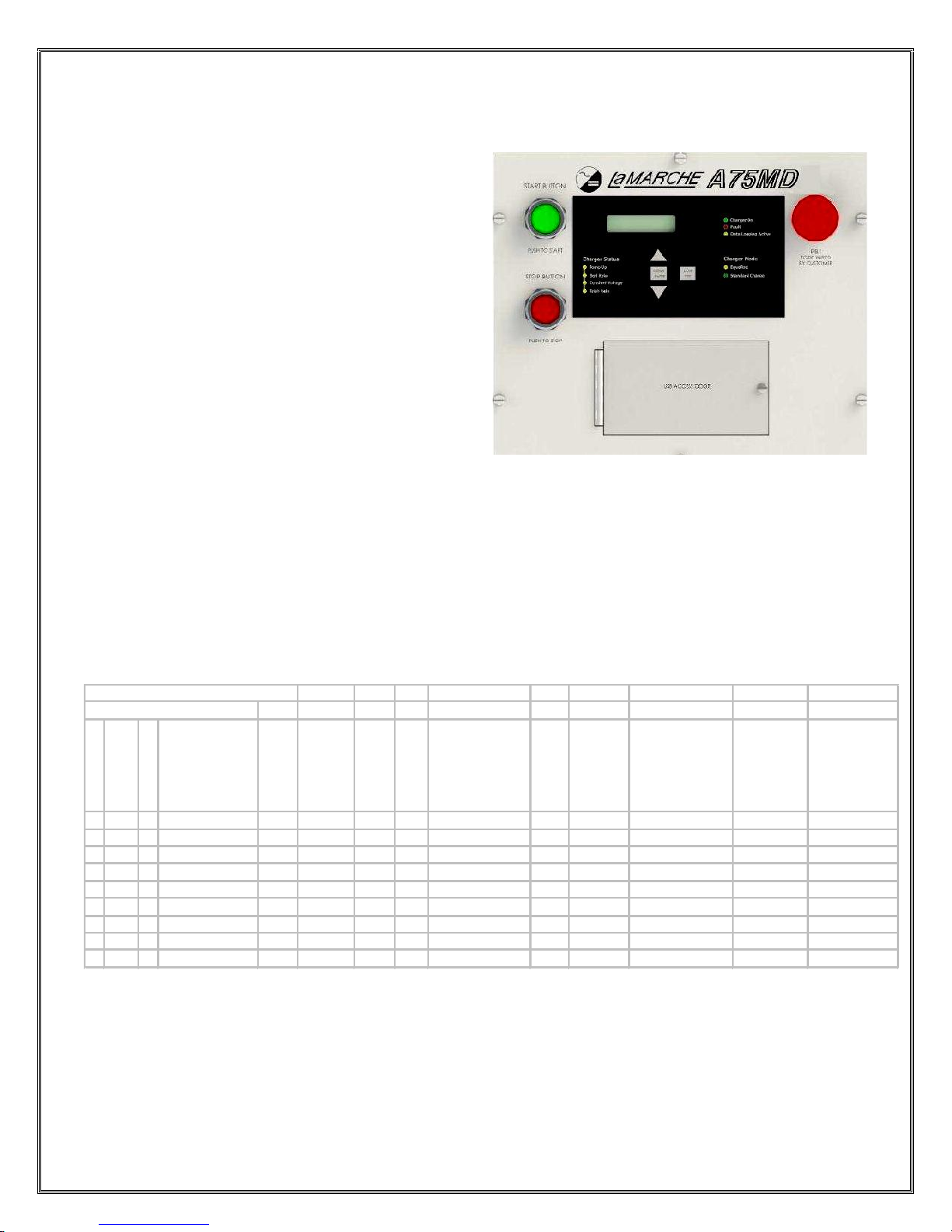
A green “START” pushbutton is used to start the charger.
A red "STOP" pushbutton allows turning off the charger when disconnecting the battery during the charge
cycle.
The lamps are as follows:
* "Charger On" Lamp
This (LED) indicator will light after the charger has successfully completed the autostart cycle and the
AC contactor has closed.
* "Ramp Up" Lamp
This (LED) indicator will light after the charger starts and is in the Ramp Up stage.
* "Start Rate” Lamp
This (LED) indicator will light when the charger is charging at the Start Rate stage.
* "Constant Voltage" Lamp
This (LED) indicator will light when the charger is charging in the Constant Voltage stage.
* "Finish Rate” Lamp
This (LED) indicator will light when the charger is charging in the Finish Rate stage.
* "Data Logging Active" Lamp (in units equipped with data logging)
This (LED) indicator will flash when the Data Logger is actively recording data.
* "Fault" Lamp
There are several conditions that will cause this (LED) to light.
1. AC Power Failure – In case of the AC input voltage failure the "Fault" lamp will flash and the display
will show AC Failure.
2. High Voltage Shutdown – If the output voltage rises above 2.7 volts per cell, the "Fault" lamp will
light. The display will show "High Voltage".
3. Override Timer – If the battery does not reach 80% charge to initiate the 3 or 6 hour timer, or if the
timer circuit fails, the override timer will shut the charger off after 12 hours of charging. The "Fault"
lamp will light and the VFD will display "Override Timer".
4. Phase 1 Override Timer - If the charge curve does not reach Phase 2 / Constant Voltage stage within
appropriate time limit (default - 6 hours), Phase 1 override timer will occur and terminate the charge.
Page 6

INSTRUCTION / TROUBLESHOOTING MANUAL FOR MODEL A75MD
PAGE6OF 22
The "Fault" lamp will light and the VFD will display "Phase 1 Override Timer".
5. Phase 2 Override Timer - If the charge curve does not reach Phase 3 / Finish Rate stage within
appropriate time limit (default – 3 hours), Phase 2 override timer will occur and terminate the charge.
The "Fault" lamp will light and the VFD will display "Phase 2 Override Timer".
6. di/dt Charge Shutoff – If the battery current in Phase 2 / Constant Voltage stage does not fall or starts
to increase the charger will shutoff with di/dt fault. The "Fault" lamp will light and the VFD will display
"DIDT".
7. System Reset - Push and hold the STOP pushbutton until the “Fault” lamp illuminates solid red, then
release the STOP pushbutton. The unit will reset and the lamp test will blink all lamps and after a
short delay the “Fault” lamp will switch from solid to blinking as part of the lamp test. System reset
may only be performed if the battery is connected.
* "Standard Charge” Lamp
This (LED) indicator will light when the charger is operating in the Standard Charge mode. This means that the
charger may run up to 3 hours after reaching the finish rate depending on the condition of the battery.
* "Equalize” Lamp
This (LED) will light when the charger is operating in the Equalize mode. This means that the charger may run
up to 6 hours after the finish rate is reached depending on the condition of the battery. See battery manual for
recommended equalize practices.
THEORY OF OPERATION
It is recommended that the connector used for the battery/charger connection have an auxiliary control
contact. (A contact that makes last and breaks first.) This contact should be wired to the battery positive on
the battery side of the connector and to Pin #2 of the terminal strip on the charger side of the connector. (The
jumper bar between Pins 1 and 2 must be removed when using the auxiliary control contact.)
The charger provides automatic AC input line compensation. The automatic compensation eliminates charging
problems that arise from a varying input line when charging continually or for two or three shift operations.
The unit is self-protecting when subjected to abnormal overloading conditions.
It should not be necessary to make any adjustments to this charger. Because of the stability of design, the unit
needs no periodic adjustment. This, along with the rugged construction and conservatively rated components,
insures long life and trouble-free operation.
Should any adjustments be necessary, a factory service representative should be contacted.
After the START pushbutton is pushed, the charger senses the connection of the battery and determines if it is
in the proper range, 1.75 volts per cell to 2.5 volts per cell, and then slowly ramps the output current up to
start the charge. The "Ramp Up" lamp will be lit during this stage. When the start rate is reached, the "Start
Rate" lamp illuminates. If a fully charged battery is connected, the charger will charge for 15 minutes and then
turn off. The VFD will alternate between "Fully Charged Battery", "Elapsed Time" and "AH Returned".
When the 80% point (2.42 volts per cell) is reached, the charger will enter the constant voltage stage and the
"Constant Voltage" lamp will illuminate. The voltage will stay constant as the current decreases. Di/dt
monitoring will start. If the battery current stops decreasing in the constant voltage stage and never reaches
the finish rate the charger will be shutoff with DIDT fault.
When the current reaches the finish rate, the "Finish Rate" lamp illuminates and the protection timer starts. 3hr timer for standard charge and 6-hr timer for equalize charge. Dv/dt monitoring will start and terminate the
charge once the battery voltage levels. If the battery voltage keeps increasing and never levels the protection
timers will terminate the charge.
When a charging cycle is completed correctly, the "Charger On" lamp will turn off. The VFD will cycle through
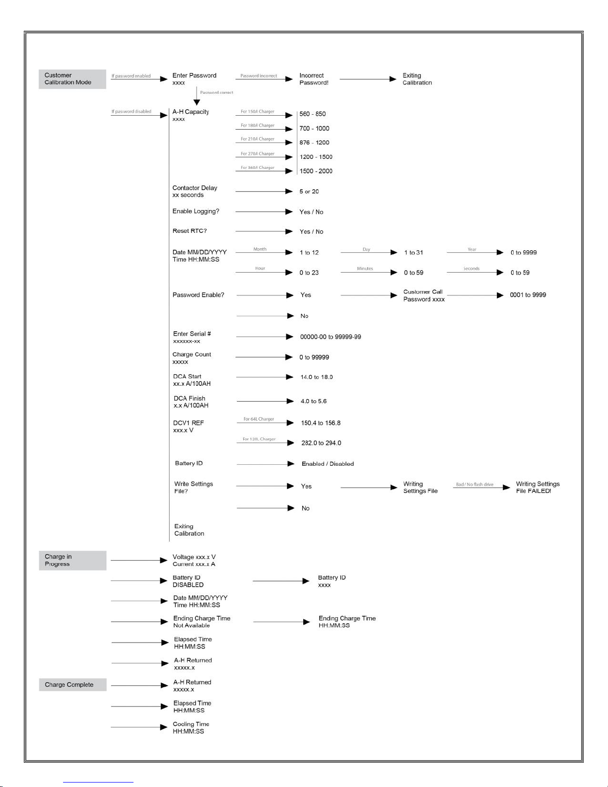
"Amp-Hour Returned", "Elapsed Time" and "Cooling Time". (Refer to flow chart on page 18)
If the discharged battery is not the correct number of cells or if the correct battery is over discharged the unit
Page 7

INSTRUCTION / TROUBLESHOOTING MANUAL FOR MODEL A75MD
PAGE7OF 22
will not start and the VFD will indicate "Wrong Battery".
A STOP pushbutton is provided to stop the charging cycle. Be sure to push this button before disconnecting
the battery during the charge cycle. If the charger goes thru a normal charge complete cycle, there is no need
to push the STOP button prior to disconnecting the battery.
For the "Standard Mode" the charger will charge the battery until the battery voltage levels. This process may
take up to 3 hours after the finish rate is reached depending on the condition of the battery. For the "Equalize
Mode" the charger will also charge the battery until the battery voltage levels but additional time will be added
if equalize mode is activated. This process may take up to 6 hours after the finish rate is reached depending on
the condition of the battery.
The MODE button is provided so that equalizing may be selected. Equalizing should be done periodically as
recommended by the battery manufacturer. This button, when activated, will start the equalize charge mode
for that cycle only. After completion of the cycle, the charger will automatically be reset to the "Standard
Charge" mode.
NOTE: The MODE button can also be used to start the charger even if a battery is discharged below 1.75 volts
per cell but is above 1.1 volts per cell. Caution must be used when using this feature to start the charger
because the initial battery voltage sensing is being disabled and the wrong battery could be connected. To
initiate this feature press and hold the MODE switch.
Disconnecting the output connector or opening the battery breaker while a battery is being
charged is not recommended. If the battery is disconnected during a charge cycle, the control will turn off
the charger, the "Charger On" lamp will go out, all timers will reset. Under these conditions the present log
record will be lost.
After starting, the 12 hour override timer is activated. This timer is independent of battery conditions and
overrides all other timing functions. The override timer will terminate the charge in the event that the 80%
timing control does not terminate the charge before the maximum time limit of 12 hours is reached. The
"Charger On" light will turn off, the "Fault" lamp will light and the display will indicate "Override Timer”. If this
occurs, push and hold the STOP pushbutton until the “Fault” lamp illuminates solid red, then release the STOP
pushbutton. The unit will reset and the lamp test will blink all lamps and after a short delay the “Fault” lamp
will switch from solid to blinking as part of the lamp test.
If the AC input line fails during the charge cycle, all internal time registers will hold their count until the power
returns. The charge cycle will then resume from where it left off. The "Fault" lamp will light and "AC Failure" is
displayed on the VFD if this condition is reached. After power is restored, the "Fault" lamp will extinguish and
the VFD will display an operating parameter screen.
A high DC voltage feature is incorporated in the charge control system. If an unusually high voltage condition
is reached as a result of a charger malfunction, the high voltage feature will terminate the charge cycle and
turn on the "Fault" light. “High Voltage” will be displayed on the VFD. In this mode the charger will not restart
again unless the charger is reset. Push and hold the STOP pushbutton until the “Fault” lamp illuminates solid
red, then release the STOP pushbutton. The unit will reset and the lamp test will blink all lamps and after a
short delay the “Fault” lamp will switch from solid to blinking as part of the lamp test. Restart the charger.
If the high voltage condition still exists the charger will again turn off. At this point, a factory service
representative should be contacted.
An additional Analog High Voltage Shutdown feature is incorporated for further protection. In the unlikely
situation of multiple software failures and the output is able to rise above 2.75 volts per cell, the Analog High
Voltage shutdown will activate. The charger will shut off and reset automatically. The “Fault” Lamp will stay lit
until the output voltage reaches an appropriate level. If upon reset the problem is not resolved and the fault
lamp does not turn off, the charger will not be able to be started. At this point, a factory service
representative should be contacted.
INSTALLATION
Page 8
INSTRUCTION / TROUBLESHOOTING MANUAL FOR MODEL A75MD
PAGE8OF 22
The La Marche Model A75MD charger is designed to operate on a specific type of battery with a specified
number of cells. The nameplate on the charger indicates the type and number of cells required. When
connecting the DC output cables to the battery, be certain the positive terminal of the charger is connected to
the positive battery terminal, and the negative terminal is connected to the negative terminal of the battery. A
grounding connection is also provided for complete protection. Install the unit so that the flow of air through
the vents is not obstructed.
A terminal block is provided within the unit for the AC input connections. Before connecting the AC input cable,
check the line power with that specified on the nameplate of the unit. Units with multiple AC input units have
taps inside, which must be set for the proper AC setting. These taps are located on terminal blocks on the
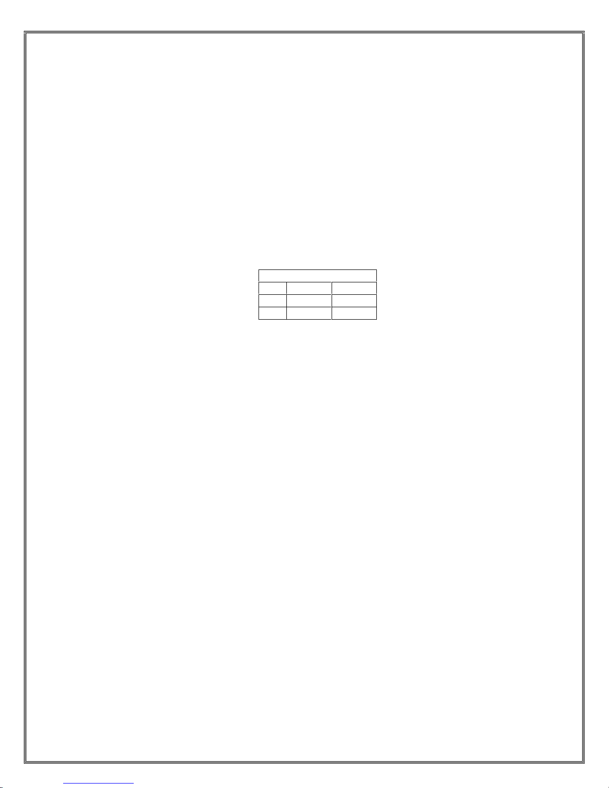
Power Transformers and on a terminal board on the Control Transformer. See tap card inside door (BELOW).
The AC input current specified on the nameplate is for rated output.
Please see the unit schematic fort more detailed information on tap settings.
Input AC breakers must be sized based on the rated value of the rated nameplate AC Input Current.
VOLTAGE CONTROL TAPS
480V
575V
CT
H2 (B)
H1 (B)
PT
2 (A)
3 (A)
Page 9
INSTRUCTION / TROUBLESHOOTING MANUAL FOR MODEL A75MD
PAGE9OF 22
OPERATION
After the installation has been completed, the Model A75MD is ready for operation. Be sure that the battery
charger is of the correct type for the battery to be charged.
CAREFULLY READ AND ADHERE TO ALL BATTERY AND BATTERY CHARGER INSTRUCTIONS AND SAFETY WARNINGS.
START-UP (or each time a battery of a different rated AH capacity is connected)
A. Apply AC voltage to the unit’s input terminals.
The VFD will display "Checking for Battery…..".
B. This configuration step only applies to initial install on site.
Access Customer Calibration Mode to verify charger settings. To access Customer Calibration press MODE and
UP arrow at the same time and hold for about 5 seconds. When in the calibration mode, advance from one
function to the next by pressing the MODE button. The MODE button is also used to advance from one digit to
the next within a function. The LAMP TEST button may be used to advance directly to the last digit within a
function. Use the UP and DOWN arrows to make selections or change settings. The LAMP TEST button is also
used to exit the Customer Calibration Mode at any time. All changes will be saved automatically. The following
settings are available to be set and/or changed by the customer (refer to flow chart on page 18):
1. A-H Capacity - Allows setting up the charger for charging different A-H capacity range within a
specified range.
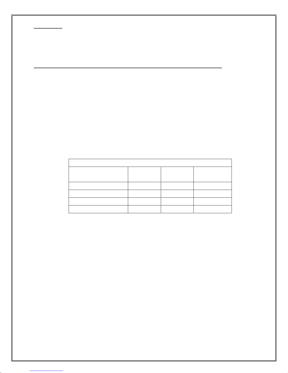
A75MD Ampere Hour Ranges
CHARGER RATING IN
AMPS
LOW AH
HIGH AH
150
560
→
850
210
875
→
1200
270
1200
→
1500
360
1500
→
2000
2. Contactor Delay – The delay on pulling in the contactor can be selected to be 5 or 20 seconds.
3. Enable Logging – YES or NO. Enables or disables the optional data logging function.
4. Reset RTC – This function allows the user to reset the Real Time Clock. Reset date is 01/01/2011 and
the Reset time is 00:00:01.
5. Date - allows the user to set the date. (Month/Day/Year)
Time - allows the user to set the time. (Hours/Minutes/Seconds)
6. Password – Allows the user to set a password for entering the Customer Calibration Mode. If YES is
selected, please enter the password and press MODE to advance. If NO is selected, press MODE to
advance to the next screen.
7. Serial number – Allows the user to enter serial number of the battery charger. In case of “plug and
play” plate replacement the serial number of the battery charger may be entered.
8. Charge count – Allows the user to set the charge count of the battery charger. In case of “plug and
play” plate replacement the actual charge count of the battery charger may be entered.
9. DCA Start* – Allows the user to adjust the Start Rate current. Adjustable range is from 14.0 to 18.0
A/100AH. (0.1 increments)
10. DCA Finish* – Allows the user to adjust the Finish Rate current. Adjustable range is from 4.0 to 5.6
A/100AH. (0.1 increments)
11. DCV1 REF* - Allows the user to adjust the Constant voltage. Adjustable range is from 2.35 to 2.45
v/c. (Displayed in “volts multiplied by cells” - 0.1 increments)
12. Battery ID – Allows the user to enable or disable Battery ID function.
13. Write Settings File – Allows the user to save the settings of the battery charger into the inserted
Page 10

INSTRUCTION / TROUBLESHOOTING MANUAL FOR MODEL A75MD
PAGE10OF 22
flash drive. The file name is called SETTINGS.CSV.
14. Saving Settings – No input required. Customer Calibration changes are saved automatically.
* NOTE: DCA Start, DCA Finish and DCV1 REF are critical charge curve parameters which should not be
changed unless the settings have been determined to be incorrect. If not set properly, incorrect adjustments
may damage the battery.
After making the desired selections in Customer Calibration, proceed to step C.
C. Connect the battery to the charger. Press the green START pushbutton. After the selected time delay
passes, the AC contactor will pull in and the charger current output will slowly ramp up to the starting rate.
During the ramp up stage, the "Ramp Up" lamp will be lit. When the start rate is reached, the "Ramp Up" lamp
will extinguish and the "Start Rate" lamp will illuminate. If a fully charged battery is connected, the charger will
charge for 15 minutes and then turn off. The VFD will alternate between "Fully Charged Battery", "Elapsed
Time" and "AH Returned".
If the charger is equipped with the optional Data Logging and it is enabled, the start up routine will be as
follows:
After applying AC, connecting the battery and pressing the START pushbutton, "Acquiring Battery ID" will be
displayed on the VFD. If a battery ID device is present, the ID will be displayed. If there is no battery ID
detected, one can be entered at this point. The first digit of the four digit ID display will flash. Use arrow
pushbuttons to enter first digit of the ID. Press MODE to advance to the next digit and select it. Press Mode
again to advance and then set the third digit. Press MODE a third time to advance to the fourth digit and select
it. Press MODE again. The charger will now start.
If an ID is not available, press the MODE button four times to assign ID 0000. The charger will start.
Please see Data Logging Option section at the end of this manual for more information.
If a battery with the wrong number of cells is connected one of four messages will be displayed:
1. High Battery – The battery voltage is above 2.5 volts per cell.
2. OVER Discharged Battery – The battery voltage is between 1.4 and 1.75 volts per cell
3. Low Battery – The battery voltage is between 1.1 and 1.4 volts per cell.
4. Extra Low – The battery voltage is between 0.5 and 1.1 volts per cell.
The charger will automatically detect and charge a battery with the terminal voltage between 1.75 and 2.5 volts
per cell. If the battery voltage is between 1.1 and 1.75 volts per cell the charger can be started by pressing
and holding the MODE button. This feature defeats the automatic detection circuit! Make sure the correct
battery is hooked up to the charger. Should the display indicate “Low Battery” a qualified battery technician
must be sent to verify battery health. Another possible circumstance may be that a battery of improper cell
count has been connected.
D. When the "80% CHARGE” point is reached the charger enters the constant voltage stage and the "Constant
Voltage" lamp will illuminate.
E. When the output current reaches finish rate, the "Finish Rate" lamp will illuminate. This is the final stage of
the charge cycle.
F. During the charging cycle you can scroll through the following screens by using the UP and DOWN
pushbuttons (refer to flow chart on page 18):
1. Voltage / Current – Displays output voltage and current
2. A-H Returned – Displays Ampere Hours returned into the battery
3. Date / Time – Displays current date and time
4. Elapsed Time – Displays the time since the charger started charging the battery.
Page 11

INSTRUCTION / TROUBLESHOOTING MANUAL FOR MODEL A75MD
PAGE11OF 22
5. Charge Time – Displays the projected total time that it will take to charge the battery.
This screen will display “Not at Finish” until the charger reaches the finish rate and the timer starts.
G. When the charge cycle is completed, the charger will turn off and the "Charger On" lamp will turn off also.
One of the following screens will be displayed (refer to flow chart on page 18):
1. A-H Returned – Displays total Ampere Hours returned to the battery during the charge cycle.
2. Elapsed Time – Displays total time that the charger was charging the battery
3. Cooling Time – Displays elapsed time from when the charger turned off.
H. If for some reason the AC input voltage fails, the "Fault" lamp will illuminate and the battery charger will
turn off. The display will indicate "AC Failure" During this interval, the charge time registers in the charger are
held at their present count. When the AC has returned to normal, the charge cycle resumes where it left off
and the "Fault" lamp extinguishes.
I. If for some reason the normal, equalize, or rate timers do not terminate the charge cycle in less than 12
hours, the override timer will time out, shut down the charger and the "Fault" lamp will illuminate. The display
will indicate "Override Timer".
J. If for some reason, the unit output voltage exceeds 2.7 volts per cell for 20 sec, an independent software
shutdown will stop the charger. The display will indicate "High Voltage" and the "Fault lamp" will illuminate. To
restart the charger it will be necessary to reset the charger. Push and hold the STOP pushbutton until the
“Fault” lamp illuminates solid red, then release the STOP pushbutton. The unit will reset and the lamp test will
blink all lamps and after a short delay the “Fault” lamp will switch from solid to blinking as part of the lamp test.
You can also reset the charger by disconnecting the battery.
K. If a fully charged battery is connected, the charger will turn off after fifteen (15) minutes, the "Charger On"
lamp will extinguish. The display will automatically scroll through the following screens:
1. Fully Charged Battery
2. A-H Returned
3. Elapsed Time
NOTE: PUSH THE STOP PUSHBUTTON TO TURN OFF THE CHARGER BEFORE DISCONNECTING THE
BATTERY DURING A CHARGE CYCLE.
Page 12
INSTRUCTION / TROUBLESHOOTING MANUAL FOR MODEL A75MD
PAGE12OF 22
DATA LOG OPTION
OBTAINING LOG FROM UNIT
In order to review the data log files from the A75MD, you will
need to have access to a computer. This can be a laptop
brought down into the mine, or a computer that is above
ground. If you plan to bring the data above ground you will
need to bring an additional USB flash drive underground. The
data logging will continue on the replacement flash drive.
The disadvantage to this is that the log will become split
making it harder to compare charge cycles. Bringing a laptop
underground allows you to just copy the file over and put the
flash drive back into the charger.
Before beginning allow the charger to finish the current
charge cycle. After the charge cycle is complete, disconnect
the battery and wait approximately one minute for the
charger to write the last charge cycle to the USB drive. There
is no indication that the file has been written so be sure to
wait a full minute after the battery has been disconnected.
When the charger has finished the charge cycle and the
battery is disconnected you may remove the USB flash drive.
It is not necessary to remove AC power from the charger; the
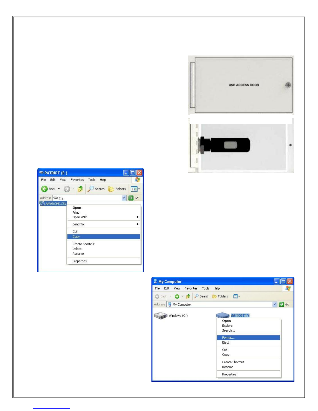
USB compartment is isolated from the power system. Open the
USB access door with a #2 Philips screwdriver and remove the
USB flash drive.
If you are reading the USB drive underground, simply copy the
“LAMARCHE.CSV” file and paste it to you desktop. Do not
delete or otherwise alter the original file. After the file has
been copied to the laptop immediately plug the USB drive back
into the charger and screw the access door closed.
If you are reading the USB drive above ground,
immediately replace the USB drive with another
USB drive that has been formatted for use with
the A75MD. Some USB drives come with file
management and/or security software preinstalled. You must format the drive to remove
these options as they make the drive
incompatible with the A75MD. Once a USB
drive has been successfully used in the A75MD,
it will not need to be formatted again.
Note: If you choose to use multiple USB drives,
the log will be spread across all of these drives;
Remove the USB flash drive
Open the USB access door with a #2 Philips
screwdriver
Copy the LAMARCHE.CSV file and paste it to your
desktop
Format the drive to remove pre-installed software
Page 13
INSTRUCTION / TROUBLESHOOTING MANUAL FOR MODEL A75MD
PAGE13OF 22
you may need to combine files to be able to compare data between charge cycles.
EVERY time a USB flash drive is inserted into the charger, the charger needs to initialize the USB drive. There
are two practical methods to force initialize the USB drive.
1. Remove the AC and DC power from the
charger and let the display completely
extinguish. Restore AC power, the card will
reboot and will automatically initialize the
USB flash drive.
2. Leave the AC supply connected and on.
Connect the battery and close the breaker.
All the LEDs on the front panel will begin
slowly flashing. Press and hold the red
STOP button on the front of the charger for
about six seconds until the red “FAULT” LED
turns on solid. Release the STOP button.
After about 10 to 30 seconds the “FAULT”
LED will begin flashing with the rest of the
LEDs.
Now the charger and the USB flash drive are ready for the next charging cycle.
UNDERSTANDING THE LOG FILE
Below is an example of an actual output log file from the A75MD data logger. The title row has been modified
to conserve space on this page. This output file “lamarche.csv” will appear on the USB flash drive. This file
can be opened using Microsoft®Excel or other spreadsheet software. This document serves to help the enduser to understand the information presented with the data log, and to interpret the results
Charger Serial Number is programmed into the software at the factory. It is written to the top of the log file
to identify which charger each log belongs to.
Charge Count shows how many charge cycles the charger has gone through. The charge count is
independent of the battery and is tied to a particular charger. The charge count will not reset even if a USB
flash drive is removed, it will increment even on new USB flash drives. The charge count is almost like an
odometer for the charger.
Press and hold the STOP button for about six seconds
Charger Serial Number 211449-01
Firmware P354S0002
Charge Count
Charger AH
Capacity
Battery ID#
Start Time
Stamp
Dead Battery
Voltage
Max DCV
During
Re-Charge
AH Returned
Re-Charge
Time(Hr:Min)
Charge
Terminate
Time
Cool Time
(Hr:Min)
Charge Type
Connected
Battery State
Fault
Indications
Termination
Type
4 1000 2 3/02/2012 8:22 271.5 318.9 11.8 0:15 3/02/2012 8:39 0:00 Standard FULLY CHARGEDNONE STOP SWITCH
5 1000 2 3/02/2012 8:44 271.7 312.7 0.7 0:01 3/02/2012 8:45 0:00 Standard NORMAL AC FAILURESTOP SWITCH
6 1000 3 3/03/2012 6:56 242.9 320.5 915 8:22 3/04/2012 11:30 20:11Standard NORMAL NONE TIME
7 1000 3 3/05/2012 3:58 264.1 325 9.3 0:15 3/06/2012 0:02 0:00 Standard FULLY CHARGEDNONE STOP SWITCH
12 1000 3 3/06/2012 9:16 240.8 320.8 919.6 8:20 3/07/2012 15:28 21:50Standard NORMAL NONE TIME
13 1000 3 3/08/2012 9:54 241.1 320.3 966 8:37 3/09/2012 14:37 18:12Standard NORMAL AC FAILURETIME
14 1000 3 3/10/2012 8:20 242.9 321.1 883.1 8:05 3/11/2012 7:37 15:11Standard NORMAL NONE TIME
15 1000 3 3/12/2012 6:53 264.5 325.4 154.4 6:00 3/12/2012 15:56 3:02 Equalize NORMAL NONE TIME
16 1000 3 3/12/2012 15:57 266.2 303.8 0 0:00 3/12/2012 15:57 0:00 Equalize NORMAL NONE STOP SWITCH
Page 14

INSTRUCTION / TROUBLESHOOTING MANUAL FOR MODEL A75MD
PAGE14OF 22
Charger AH Capacity is the Amp-Hour Capacity that the charger has been set for. This is generally only set
once, but it can be adjusted for different Amp-Hour batteries with-in the charger’s range.
Battery ID # is the specific ID set for each battery. If a Battery ID Module is installed the battery ID will be
automatically set. If no module is installed, the charger will request a manually entered ID before a charge is
started. This allows for easy identification of the battery being charged.
Start Time Stamp is simply the date and time that the charge was started. This is based on a real-time clock
running off of a coil-cell battery on the charger’s main circuit board.
Dead Battery Voltage is the open circuit voltage from the battery just moments before the charger has
started. At this point, the battery’s state of charge has not been determined yet. This shows just how
discharged the battery was prior to starting the charge.
Max DCV During re-charge displays the highest DC Voltage achieved during re-charge. This allows us to
see if the charger had delivered enough voltage to the battery to raise the specific gravity.
AH Returned shows how many Amp Hours the charger actually delivered to the battery during the charge
cycle. There are no efficiency or Puekert factors involved. This is simply the Amp-Hours output.
Re-charge Time is the total elapsed time spent on charge. This does not including the cooling time. If the
charger experiences an AC Failure this timer “pauses.” Once AC power is restored the timer will resume, and
the total time the battery was recharging is saved. Example: A battery is charging for two hours, the AC power
fails and is not restored for an hour. Upon restoration of AC power the battery charges for an additional six
hours. The recharge time is not the nine hour difference between Start Time and Charge Terminate Time, it is
only the eight hours that the battery was actually under charge.
Charge Terminate Time, similar to the start time stamp, is simply the date and time that the battery was
removed from the charger.
Cool Time is time elapsed from the end of the charge until the battery is disconnected (or battery breaker is
closed). Using this data allows the customer to determine if the end-user is letting the battery cool-down
before putting the battery back to use. Cool time may not represent the actual time the battery was allowed to
cool down. If the battery is disconnected from the charger and given additional time to cool, the charger is not
able to monitor this additional time. La Marche recommends leaving the battery connected until the moment of
battery exchange, to allow for proper measurement of cool time.
Charge Type shows whether the charger was set to a "Standard" charge cycle or an "Equalize" charge cycle.
Equalize can only be activated manually via the front panel membrane.
Connected Battery State indicates the status of the battery that was connected to the battery. If the
battery was determined to be fully charge after 15 minutes, the log shows FULLY CHARGED. If the battery
went through a normal recharge requiring at least 3-hours of finish-rate charging, the log shows NORMAL.
Fault Indications are any internal or external event that may have interrupted the recharge. If an AC
FAILURE occurs during the charge cycle, once power is restored the charger will pick-up where it left off and
finish charging the battery. The log will show AC FAILURE. If di/dt fault occurs during the charge cycle, DIDT
FAULT will be logged as the fault indication. If any of the override timers occur they will be logged as well.
Termination Type shows what method was used to terminate the charge. The three types of termination are:
STOP SWITCH (manually pressing the stop pushbutton before completing the charge or after but with fault
indication present), TIMER (letting the charger complete the cycle on its own with timer) and DVDT (letting the
charger complete the cycle on its own with dv/dt termination).
Page 15

INSTRUCTION / TROUBLESHOOTING MANUAL FOR MODEL A75MD
PAGE15OF 22
This next section details each of the charge cycles shown in the log file example above.
Charge Cycle 1, 2, 3:
Charge cycles 1, 2, and 3 do not appear on this log file because the USB flash drive they were written to has
been removed. It is also possible that no flash drive was present at the time of these charge cycles. The
charge count is stored in the internal memory of the charger, and will increment regardless of USB status.
Charge Cycle 4:
This battery was fully charged at the moment it was plugged in, the charger determined the battery was fully
charged and terminated the charge cycle after 15 minutes. The battery was not allowed any cool time.
Charge Cycle 5:
This battery charged for only one minute when AC power was lost. Based on the dead battery voltage of 271.7
and the Max DCV of 312.7, this battery was already fully charged. The stop pushbutton was pressed before AC
power returned, which prevented the charger from automatically resuming charge. Since the charger was
unable to complete the initial 15 minutes of charge, it could not determine that the battery is fully charged.
Charge Cycle 6:
This is normal recharge cycle for a mostly depleted battery. The battery charged for 8 hours 22 minutes before
the charge cycle was terminated by the charger, the charger returned 915 Amp-Hour to the battery. The
battery was allowed 20 hours 11 minutes of cool time before it was disconnected.
Charge Cycle 7:
This battery was fully charged at the moment it was plugged in, the charger determined the battery was fully
charged and terminated the charge cycle after 15 minutes.
Charge Cycles 8, 9, 10, 11:
The USB flash drive was removed after charge cycles 7. It is possible that no flash drive was present at the
time of these charge cycles, or these charge cycles have been written to another flash drive. The charge count
is stored in the internal memory of the charger, and will increment regardless of USB status.
Charge Cycle 12:
This is normal recharge cycle for a mostly depleted battery. The battery charged for 8 hours 20 minutes before
the charge cycle was terminated by the charger, the charger returned 919.6 Amp-Hour to the battery. The
battery was allowed 21 hours 50 minutes of cool time before it was disconnected.
Charge Cycle 13:
This is normal recharge cycle for a mostly depleted battery. AC Failure did occur during the charge cycle. The
charger automatically resumed charging upon return of AC power. The battery charged for 8 hours 37 minutes
before the charge cycle was terminated by the charger, the charger returned 966 Amp-Hour to the battery.
The battery was allowed 18 hours 12 minutes of cool time before it was disconnected.
Charge Cycle 14:
This is normal recharge cycle for a mostly depleted battery. The battery charged for 8 hours 5 minutes before
the charge cycle was terminated by the charger, the charger returned 883.1 Amp-Hour to the battery. The
battery was allowed 15 hours 11 minutes of cool time before it was disconnected.
Charge Cycle 15:
When the charge cycle was started the user initiated an equalize charge, which forces the charger to charge for
six hours once reaching finish rate. Since the battery charged for exactly 6 hour, it is likely that is was already
near full charge. The charger returned 154.4 Amp-Hour to the battery. The battery was allowed 3 hours 2
minutes of cool time before it was disconnected.
Charge Cycle 16:
This charge cycle was manually stopped using the charger stop switch. The re-charge time shows 0:00
because the charger had not yet completed a full minute of charging before being stopped.
Page 16
INSTRUCTION / TROUBLESHOOTING MANUAL FOR MODEL A75MD
PAGE16OF 22
COMBINING SPLIT LOG FILES
There may be situations where the user has to use a different USB flash drive for data logging. One example is the
data files need to read above ground, so the flash drive is replaced. If this were to happen the data log would be
separated onto multiple files. This could make comparing charge cycles difficult. This page will show you how to
recombine these multiple log files into one single file with all charge cycles.
The example below shows the procedure using Microsoft®Excel 2003. All other spreadsheet software offers this
same functionality, however the procedure may vary slightly
The separate files would all have the same name, just on different flash drives. If possible open both files directly
from the flash drives, otherwise copy only one of them to the desktop and run the other from the flash drive.
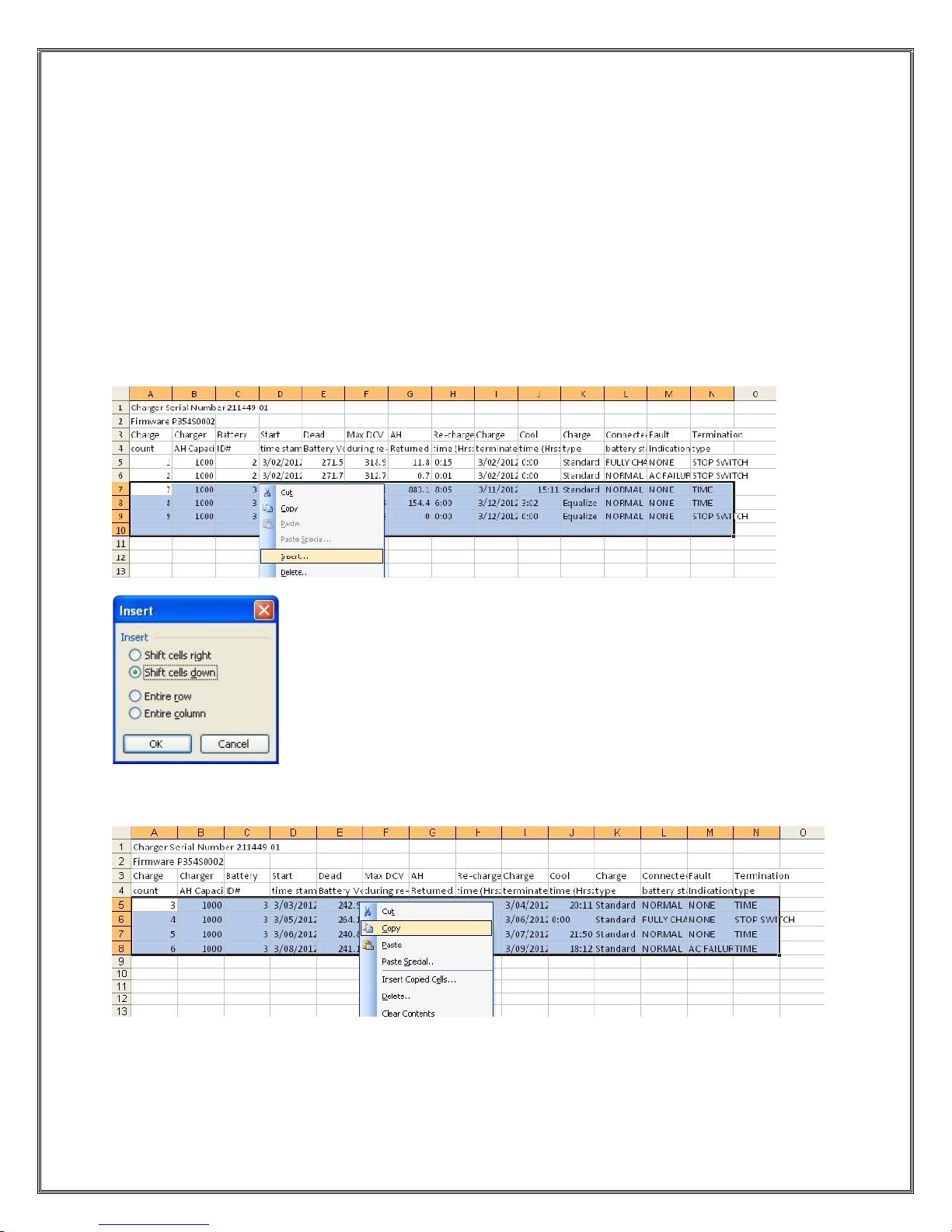
Looking at the images below we will be adding charge cycles 4-6 that are on one flash drive, to the rest of the data
log on another flash drive. Check to see how many charge cycles you will be adding. In this example we will be
adding four cycles between charge cycle 2 and charge cycle 7.
Select the area under charge cycle 2 as shown above. Notice that we are selecting
four rows tall and enough columns wide to cover all of the data headings. Right click
the selected area and click insert.
An “Insert” dialog box will pop up asking what to do with the existing cells. Select
shift cells down and press the OK button. This will insert empty cells in the area we
selected and will shift the existing data down.
Now we will go over to the other log file that is open. We need to select all of the cells that are related to charge
cycles 3-6 as shown below. Right click the selected are and click Copy.
After the selection has been copied we need to go back to the first data file. We want the copied data to take the
place of the blank cells we created. Select the cell directly under charge cycle 2 and paste the data by right clicking
the cell and selecting paste.
Page 17
INSTRUCTION / TROUBLESHOOTING MANUAL FOR MODEL A75MD
PAGE17OF 22
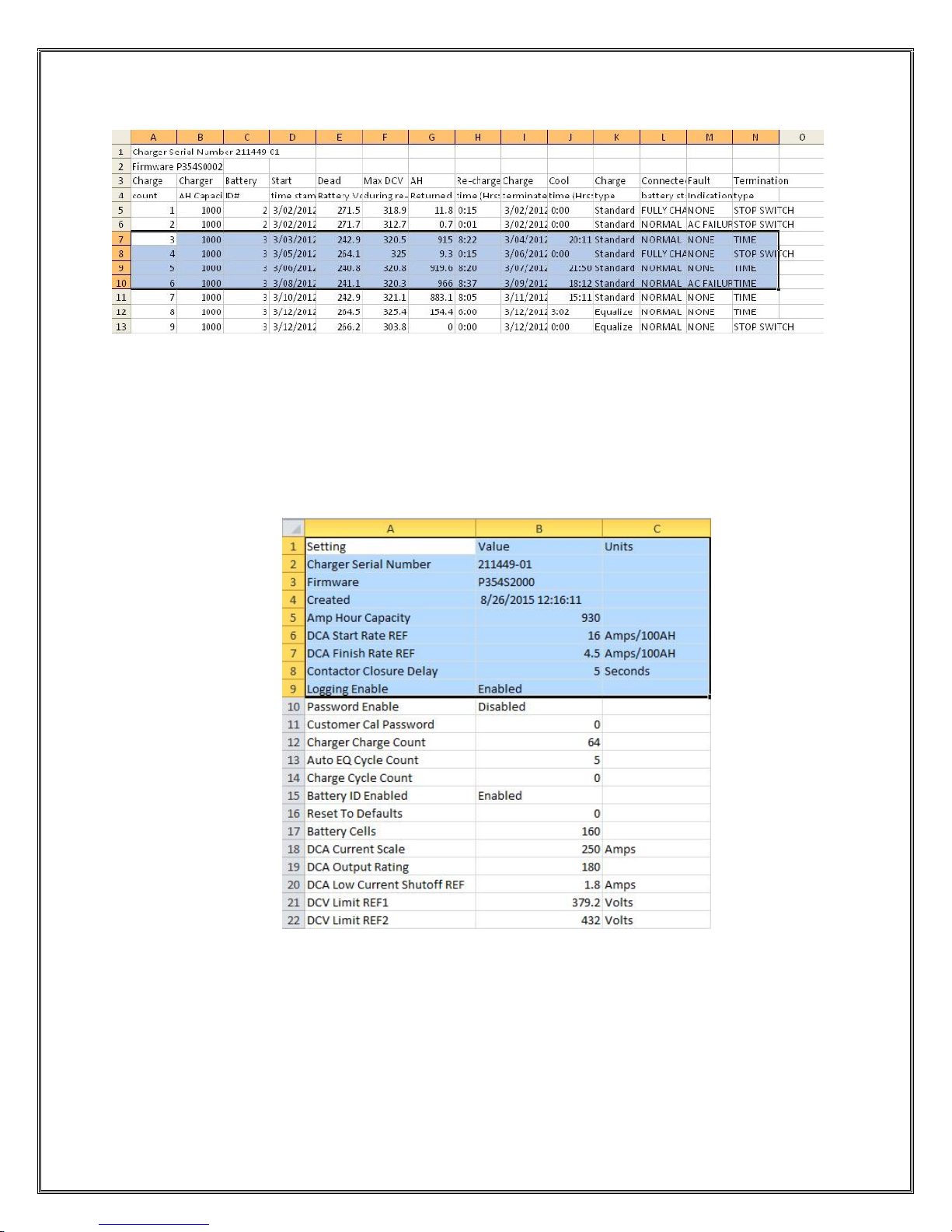
Your final output will be different than this example as you will not have the same data. That said all of your charge
cycle data should be listed in the correct order, similar to what is shown in the image below.
If you save the log file keeping the name as LAMARCHE.CSV the flash drive can be plugged back into the charger and
the logging will continue from the end of the of the log file as if it were never removed.
SETTINGS.CSV file
Below is an example of the file called SETTINGS.CSV. It contains information on all of the settings of the charger.
This file may be saved into the inserted flash drive by accessing the Customer Calibration Mode. Scroll through
the calibration menu until “Write Settings File” is displayed. Select “YES” and wait for the file to be written.
Looking at the output file there are three columns: Setting, Value and Units. This file provides helpful
information about the charger. Should any issues arise and service department is required to be contacted this
file may be downloaded.
Page 18
INSTRUCTION / TROUBLESHOOTING MANUAL FOR MODEL A75MD
PAGE18OF 22
FLOW CHART
Page 19

INSTRUCTION / TROUBLESHOOTING MANUAL FOR MODEL A75MD
PAGE19OF 22
A75MD TROUBLESHOOTING
INSTRUCTIONS
Before troubleshooting unit, check for shipping damage. (i.e. broken wires, loose connections, etc.)
Quick-Check A75MD Trouble Analysis
Problem: Blown AC input fuse.
1. Check AC input voltage with tap setting on power transformer and control transformer. If AC input
and tap setting agree, see step #2.
2. Check AC input current draw after replacing blown AC fuse.
3. If AC input fuse clears when the AC contactor pulls in make sure the correct AC fuses are being
used, time delay fuses
4. Disconnect the secondary leads from P.T. to SCR/Diode modules. If fuse still clears, problem is in
the (P.T.) power transformer. If fuse is good, problem could be in the SCR/Diode module.
SEE SCR/SCR TROUBLESHOOTING GUIDE
5. Replace Plug and Play Assembly.
Problem: Blown DC fuse.
1. Make sure the correct type of fuse is being used.
2. Check all connections to DC fuse to be certain they are tight.
3. Check polarity of output cables and output connector.
4. Check SCR/SCR modules and diode SD4 for shorts. SEE SCR/SCR MODULE TROUBLESHOOTING GUIDE.
5. Replace Plug and Play Assembly.
Problem: Blown control transformer fuse CTF.
1. Defective contactor (shorted coil)
2. Control taps set wrong on control transformer H1 - H2.
3. Defective control transformer.
Problem: Contactor does not pull in.
1. Check AC input voltage and fuses.
2. Check DC voltage at DC output terminals (battery connected).
3. Check AC voltage output on control transformer.
4. If 120 Vac. is present at AC contactor coil, contactor may be defective.
Page 20

INSTRUCTION / TROUBLESHOOTING MANUAL FOR MODEL A75MD
PAGE20OF 22
SCR/SCR MODULES TROUBLESHOOTING GUIDE
1. Disconnect the positive and negative bus bars from module.
2. Disconnect the secondary wire of power transformer from the SCR/SCR module.
3. Remove both Plug and Play assembly plugs.
4. Measure the resistance from anode to cathode of each SCR. This measurement should read as high
resistance. If the leads are reversed the measurement should also read as high resistance.
5. Measure the resistance of the diode module from anode to cathode. When forward biased, resistance
should read low, when reverse biased, resistance should read high.
6. If the resistance readings do not match the steps above, it is likely that the SCR module or diode module is
defective.
Page 21

INSTRUCTION / TROUBLESHOOTING MANUAL FOR MODEL A75MD
PAGE21OF 22
General Maintenance Procedure
Yearly
1. Blow out charger with a low-pressure air hose.
2. Make sure all connections are tight.
3. Perform a visual check on all internal components.
4. Check front panel meters for accuracy.
5. Check magnetics, components and wiring for signs of excessive heat.
Page 22

INSTRUCTION / TROUBLESHOOTING MANUAL FOR MODEL A75MD
PAGE22OF 22
MANUFACTURER’S WARRANTY
All La Marche Manufacturing Co. equipment has been thoroughly tested and found to be in proper operating condition upon
shipment from the factory and is warranted to be free from any defect in workmanship and material that may develop
within one year from date of purchase. In addition to the standard one (1) year warranty, La Marche warrants its
magnetics on a parts replacement basis only for four (4) more years under normal use.
Any part or parts of the equipment (except fuses, DC connectors and other wear-related items) that prove defective within
a one (1) year period shall be replaced without charge providing such defect, in our opinion, is due to faulty material or
workmanship and not caused by tampering, abuse, misapplication or improper installation. Magnetics are warranted for five
(5) years after date of purchase. During the last four (4) years of this five (5) year warranty period, the warranty covers
parts replacement only, and no labor or other services are provided by La Marche, nor is La Marche obligated to reimburse
the owner or any other person for work performed.
Should a piece of equipment require major component replacement or repair during the first year of the warranty period,
these can be handled in one of two ways:
1. The equipment can be returned to the La Marche factory to have the inspections, parts replacements
and testing performed by factory personnel. Should it be necessary to return a piece of equipment or
parts to the factory, the customer or sales representative must obtain authorization from the factory.
If upon inspection at the factory, the defect was due to faulty material or workmanship, all repairs will
be made at no cost to the customer during the first year. Transportation charges or duties shall be
borne by purchaser.
2. If the purchaser elects not to return the equipment to the factory and wishes a factory service
representative to make adjustments and/or repairs at the equipment location, La Marche's field service
labor rates will apply. A purchase order to cover the labor and transportation cost is required prior to
the deployment of the service representative.
In accepting delivery of the equipment, the purchaser assumes full responsibility for proper installation, installation
adjustments and service arrangements. Should minor adjustments be required, the local La Marche sales representative
should be contacted to provide this service only.
All sales are final. Only standard LaMarche units will be considered for return. A 25% restocking fee is charged when
return is factory authorized. Special units are not returnable.
In no event shall La Marche Manufacturing Co. have any liability for consequential damages, or loss, damage or expense
directly or indirectly arising from the use of the products, or any inability to use them either separately or in combination
with other equipment or materials, or from any other cause. In addition, any alterations of equipment made by anyone
other than La Marche Manufacturing Co. renders this warranty null and void.
La Marche Manufacturing Co. reserves the right to make revisions in current production of equipment, and assumes no
obligation to incorporate these revisions in earlier models.
The failure of La Marche Manufacturing Co. to object to provisions contained in customers' purchase orders or other
communications shall not be deemed a waiver of the terms or conditions hereof, nor acceptance of such provisions.
The above warranty is exclusive, supersedes and is in lieu of all other warranties, expressed or implied, including any
implied warranty of merchantability or fitness. No person, agent or dealer is authorized to give any warranties on behalf of
the Manufacturer, nor to assume for the Manufacturer any other liability in connection with any of its products unless made
in writing and signed by an official of the manufacturer.
 Loading...