

Page 1
A36F - 3 PHASE - INSTRUCTIONS AND TROUBLESHOOTING
MODEL
ISSUE DATE: 9842 – 11/95
A36F
THREE PHASE
BATTERY CHARGER
ECN/DATE
12251 - 8/98
12444 – 11/98 10845 – 4/97
106 BRADROCK DRIVE
DES PLAINES, IL. 60018
(847) 299-1188
FAX: (847) 299-3061
INSTRUCTION DRAWING NUMBER:
LA36F3PHASE-1
Page 2

A36F - 3 PHASE - INSTRUCTIONS AND TROUBLESHOOTING
IMPORTANT SAFETY INSTRUCTIONS
FOR THE
LA MARCHE POWER CONVERSION EQUIPMENT
SAVE THESE INSTRUCTIONS
This manual contains important safety and operating instructions for the La Marche Power Conversion
Equipment.
Before using this equipment, read all instructions and cautionary markings on (1) unit, (2) battery, and
(3) product using the battery.
CAUTION: To reduce risk of injury, use only the type of batteries specified on nameplate.
Other types of batteries may burst causing personal injury and damage.
Do not expose equipment to rain or snow.
Do not operate equipment if it has received a sharp blow, been dropped, or otherwise damaged in
any way; take it to a qualified serviceman.
Do not disassemble this unit; take it to a qualified serviceman when service or repair is required.
Incorrect re-assembly may result in a risk of electric shock or fire.
To reduce risk of electric shock, disconnect this unit from the a.c. supply, or batteries and loads
before attempting any maintenance or cleaning. Turning off controls will not reduce this risk.
WARNING - RISK OF EXPLOSIVE GASSES WORKING IN VICINITY OF A BATTERY IS
DANGEROUS. BATTERIES GENERATE EXPLOSIVE GASES DURING NORMAL BATTERY
OPERATION. FOR THIS REASON, IT IS OF UTMOST IMPORTANCE THAT EACH TIME BEFORE
USING THIS UNIT, YOU READ THIS MANUAL AND FOLLOW THE INSTRUCTIONS EXACTLY.
To reduce risk of battery explosion, follow these instructions and those published by the battery
manufacturer and manufacturer of any equipment you intend to use in the vicinity of the battery.
Review cautionary marking on all products.
PERSONAL PRECAUTIONS:
ØØ Someone should be within range of your voice or close enough to come to your aid when you work
near a battery.
ØØ Have plenty of fresh water and soap nearby in case the battery electrolyte contacts skin, clothing, or
eyes.
ØØ Wear complete eye protection and clothing protection. Avoid touching eyes while working near a
battery.
ØØ If the battery electrolyte contacts skin or clothing, wash immediately with soap and water. If the
electrolyte enters the eye, immediately flood the eye with running cold water for at least ten (10)
minutes and get medical attention immediately.
ØØ Never smoke or allow a spark or flame in vicinity of a battery.
ØØ Be extra cautious to reduce risk of dropping a metal tool onto a battery. It might spark or short-
circuit the battery or other electric part that may cause an explosion.
Page 2 of 21
Page 3

A36F - 3 PHASE - INSTRUCTIONS AND TROUBLESHOOTING
ØØ Remove personal metal items such as rings, bracelets, necklaces, and watches when working with a
battery. A battery can produce a short-circuit current high enough to weld a ring or the like to
metal, causing a severe burn.
ØØ NEVER charge a frozen battery.
ØØ If necessary to remove the battery connections, always remove grounded terminal from the battery
first. Make sure all loads are disconnected and unit is off, so as not to cause an arc.
ØØ Be sure the area around the battery is well ventilated while the battery is being charged.
ØØ When cleaning battery terminals, be careful to keep corrosion from coming in contact with eyes.
ØØ Study all the battery manufacturer’s specific precautions such as removing or not removing cell caps
while charging, recommended rates of charge, and maintenance procedures.
UNIT LOCATION
ØØ Never place this unit directly above the battery. Gases from the battery will corrode and damage
equipment.
ØØ Never allow the battery electrolyte to drip on this unit when reading the specific gravity or filling the
battery.
ØØ Do not operate this unit in a closed-in area or restrict ventilation in any way.
ØØ Do not set a battery on top of this unit.
D.C. CONNECTION PRECAUTIONS
Connect and disconnect d.c. output cables only after setting all of this unit's switches to off position and
removing a.c. input supply.
Page 3 of 21
Page 4
A36F - 3 PHASE - INSTRUCTIONS AND TROUBLESHOOTING
RECEIVING INSTRUCTIONS
AND
GENERAL EQUIPMENT INFORMATION
CAUTION: To ensure safe installation and operation, the information given in the instruction manual
should be read and understood before installing or using the equipment.
RECEIVING INSTRUCTIONS
Unpacking and Inspection: Examine the shipping crate upon arrival. If there is obvious damage, describe
on the receiving documents. Within a few days after delivery, the equipment should be uncrated and
carefully inspected for hidden damages. When removing packaging material, be careful not to discard
any equipment, parts, or manuals. If any damage is detected you should:
1. File a claim with the carrier within five (5) days.
2. Send a copy of the claim to La Marche Mfg. Co.
3. Call La Marche Mfg. For a RETURN MATERIAL AUTHORIZATION NUMBER.
Failure to properly file a claim for shipping damages, or provide a copy of the claim to La
Marche Mfg., may void warranty service for any physical damages reported for repair.
HANDLING
WARNING: Equipment can be very heavy, and top-heavy. Use adequate manpower or
equipment for handling. Until the equipment is securely mounted, care must be used to
prevent the equipment from being accidentally tipped over.
NOMENCLATURE PLATES
Each piece of La Marche Mfg. Equipment shipped is identified by part number on the nomenclature plate.
ADJUSTMENTS
All equipment is shipped from the factory fully checked and adjusted. Do not make any adjustments
unless the equipment has been powered-up and the settings have been determined to be incorrect.
SPARE PARTS
To minimize downtime during installation or normal service, it is advisable to purchase spare fuses, circuit
boards and other recommended components. Please refer to the list of recommended spare parts and
their La Marche Mfg. Part numbers included with the instruction manual. It is recommended that spare
fuses be ordered for all systems.
To order spare parts, please contact La Marche Mfg. (847)-299-1188 during business hours and ask for
the Parts Department.
Page 4 of 21
Page 5

A36F - 3 PHASE - INSTRUCTIONS AND TROUBLESHOOTING
1.0 GENERAL
The La Marche Model A36F-3 PHASE is a controlled ferroresonant float charger designed to power a load
while charging a battery. The A36F-3 Phase is filtered and may be used without a battery.
The solid state electronic control circuit provides excellent line-load voltage regulation, current limiting,
timer, and alarm package with relays are standard.
The Model A36F-3 PHASE is available in a wide range of a.c. input voltages, with 24 volt and 48 volt d.c.
outputs in output currents ranging from 100 to 400 amps.
2.0 OUTPUT RATINGS
2.1 D.C. VOLTAGE
The A36F-3 PHASE series provide separate voltage adjustments for floating or equalizing lead or nickel
cadmium cells. The float or equalize mode of operation is selected by a switch located on the front of the
rectifier.
The factory settings are as follows:
§ Float voltage Equalize voltage
2.25 volts/cell (Lead) 2.35 volts/cell (Lead)
1.40 volts/cell (N.C.) 1.55 volts/cell (N.C.)
2.2 VOLTAGE RANGE
§ Float Equalize
2.12 - 2.3 volts/cell +/- .1 volts (Lead) 2.25 - 2.40 volts/cell +/- .1 volts (Lead)
1.39 - 1.45 volts/cell +/- .1 volts (N.C.) 1.50 - 1.60 volts/cell +/- .1 volts (N.C.)
2.3 OUTPUT CURRENT
§ Three Phase - 100 to 400 amps - 24Vdc, or 48Vdc
2.4 REGULATION
Steady state output voltage remains within +/- 1/2% of rated voltage for any load current from no load
to full load and for input voltages within the rated range.
2.5 FILTERING
Three phase units are 30Mv. RMS when connected to a battery with an ampere-hour capacity of four
times the output current capacity of the charger (32 DBRN “C” message weighting on units’ 48 volts or
less).
2.6 MEAN TIME BETWEEN FAILURE
The mean time between failure (MTBF) in excess of 175,000 hours at 50 degrees C.
Page 5 of 21
Page 6
A36F - 3 PHASE - INSTRUCTIONS AND TROUBLESHOOTING
3.0 INPUT RATINGS
3.1 A.C. VOLTAGE
The units are rated for three phase inputs and are available in 208/ 240 or 480 v.a.c. three phase inputs.
3.2 INPUT FREQUENCY RANGE
57 to 63 Hz. (60 HZ nominal) 47 to 57 HZ. (50 HZ nominal)
3.3 INPUT CURRENT - (Refer to TABLE 1) (Based on 100% load)
4.0 TYPICAL ELECTRICAL SPECIFICATIONS
Refer to TABLE 1 for a.c. input draw, heat losses (based on 85% eff, & .9pf at rated load). Refer to 7.0
installation instructions for proper wire size.
24 VOLT DC OUTPUT AC INPUT
MODEL NUMBER DC AMPERES 208 240 480 CASE NO. HEAT DISSIPATION BTU/HR.
A36F-200-24V 200 20 17 9 43 6,100
A36F-300-24V 300 29 25 12 43 9,400
A36F-400-24V 400 40 33 17 43 12,300
48 VOLT DC OUTPUT AC INPUT
MODEL NUMBER DC AMPERES 208 240 480 CASE NO. HEAT DISSIPATION BTU/HR.
A36F-100-48V 100 20 17 9 43 3,700
A36F-200-48V 200 39 34 17 43 6,100
A36F-300-48V 300 59 51 25 44 9,400
A36F-400-48V 400 78 68 34 44 12,300
Table 1
5.0 STANDARD FEATURES
5.1 INPUT PROTECTION
§ AC BREAKER
A three-pole circuit breaker opens all three legs of the a.c. service. Refer to parts list for rating.
5.2 OUTPUT PROTECTION
D.c. fuse or d.c. breaker positive or negative ground.
Current limiting is adjustable from 90% to 115% of rated load, limits the D.C. Output current.
Factory set at 115% of rated output. Refer to parts list for rating.
Page 6 of 21
Page 7

A36F - 3 PHASE - INSTRUCTIONS AND TROUBLESHOOTING
5.3 STATUS/ALARM INDICATORS
A green pilot light indicator illuminates to indicate a.c. voltage is present to the rectifier.
A red a.c. power failure light with Form “C” contacts for customer connections.
§ Float Indicator
A green LED illuminates to indicate that the rectifier is in the float mode of operation.
§ Equalize Indicator
A yellow LED illuminates to indicate that the rectifier is in the equalize mode of operation.
5.4 PARALLELING
This rectifier will parallel with any other La Marche Model A36F-3 PHASE Charger.
5.5 LOAD SHARING
A load sharing circuit is provided on the terminal board. When connected, two (2) or more La Marche
A36F-3 PHASE units are forced to share the load equally within +/- 5%. Individual unit d.c. amp output
must be greater than 10% of nameplate rated output.
5.6 CURRENT WALK IN
Output current will gradually increase after the rectifier is initially turned on reducing current surges.
5.7 EMERGENCY RESTORATION
This rectifier may be connected to a battery, which is heavily discharged and recharge it without clearing
any protective devices while powering d.c. loads.
5.8 METERS
Digital meter is standard with “INFORMER” option.
5.9 MOUNTING
These cases are designed for floor mounting. See cabinet dimensions sheet (included in manual) for
more information.
6.0 ENVIRONMENTAL RATINGS
6.1 OPERATING AMBIENT TEMPERATURE
0-50 degrees C (32-122 degrees F)
6.2 STORAGE TEMPERATURE
-40 to +85 degrees C (-40 to +185 degrees F)
6.3 HUMIDITY
This rectifier is capable of operating in an ambient relative humidity range of 0-95% (non-condensing).
Page 7 of 21
Page 8

A36F - 3 PHASE - INSTRUCTIONS AND TROUBLESHOOTING
6.4 SHOCK
The rectifier in its shipping container, withstands shock developed when one edge of the container is
dropped six (6) inches while the opposite edge is resting on the ground, or it is dropped two (2) inches
on any surface without any physical damage or degradation of the electrical performance.
6.5 VIBRATION
The rectifier in its shipping container withstands vibration encountered in shipping without physical
damage or degradation of the electrical performance.
6.6 ALTITUDE
This rectifier is capable of operation at altitudes to 10,000 feet at an ambient temperature of
up to +40 degrees C.
6.7 VENTILATION
The unit should be mounted so that ventilating openings are not blocked and air entering the cabinet
does not exceed 122 degrees F.
6.8 AUDIBLE NOISE
Audible noise is not greater than 65 DBA measured at 5 feet from any surface on the unit enclosure.
7.0 INSTALLATION INFORMATION
7.1 MINIMUM WIRE SIZES
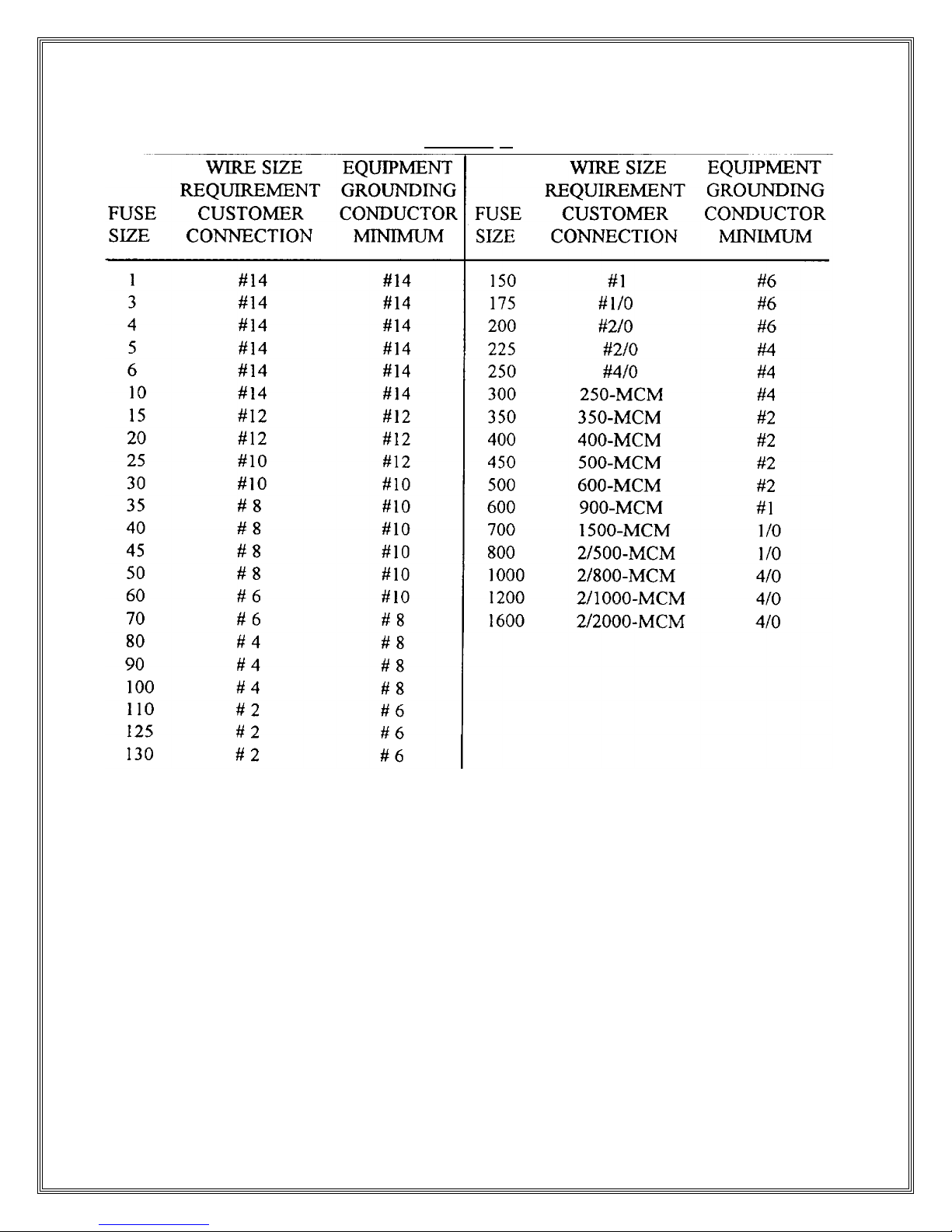
Table 2 lists the a.c. input and the D.C. output minimum wire size requirements. At distances exceeding
10 feet, the d.c. wire size should be chosen to keep the voltage difference between the units d.c.
output terminals and the battery at less than 1/2 volt when the unit is fully loaded. See Section 7.6 for
“POWER CABLING FORMULAS”. The total loop length is twice the distance from the wiring point to the
unit.
7.2 WIRE SIZE TABLE
(Refer to TABLE 2)
7.3 NATIONAL CODES
These wire sizes are based on those recommended in the National Electric Code Table 310-16 for copper
wire at 75 degrees C conductor temperature operating in an ambient of 30 degrees C. For higher
operating temperatures refer to the derating factors in the National Electric Code Table 310-16.
7.4 FIELD GROUND TERMINAL
This terminal should be connected to an earth ground. The size of the conductor is based on National
Electric Code Table 250-95 for copper wire at 75 degrees C. (See Table #3 for recommended wire sizes.)
7.5 MOUNTING
Install the rectifier so that the flow of air through the ventilators is not obstructed.
Page 8 of 21
Page 9
A36F - 3 PHASE - INSTRUCTIONS AND TROUBLESHOOTING
TABLE 2
7.6 POWER CABLING FORMULAS
The following section may be used to calculate the wire size requirements for wire lengths in excess of 10
ft. (Refer to TABLE 3)
CMA= CROSS SECTION OF WIRE IN CIRCULAR MILS.
A = CURRENT DRAIN IN AMPERES.
LF = CONDUCTOR LOOP FEET.
MAX AMP= MAXIMUM ALLOWABLE CURRENT FOR A GIVEN VOLTAGE DROP (IN AMPERES).
AVD = ALLOWABLE VOLTAGE DROP.
K= 11.1 CONSTANT FACTOR FOR COMMERCIAL (TW TYPE)
Page 9 of 21
Page 10

A36F - 3 PHASE - INSTRUCTIONS AND TROUBLESHOOTING
COPPER WIRE (KS5482-01)
WIRE SIZE REQUIRED
CMA = (A*LF*K) / AVD
CURRENT CAPACITY (IN AMPS) (SEE TABLE 3)
MAX AMPS = (CMA* AVD)/(LF*K)
8.0 ELECTRICAL CONNECTIONS & FIELD WIRING
Terminal blocks are provided for connecting the a.c. input and d.c. output. A ground wire must be
connected to the unit’s case ground.
8.1 A.C. INPUT
Make sure that a.c. power is off at the main a.c. breaker box before installation begins.
Make sure that the input source is the same voltage and frequency as that which is marked on the
nameplate of the rectifier. On multivoltage, input units check tap jumpers with the unit to make sure
they agree with input voltage.
The wire size and distribution fusing should be adequate for the nameplate input current of the rectifier
plus the overload current (usually 10%-15% higher than the nominal rating).
An adequate earth ground lead should be connected to the terminal marked “GROUND” or “GND”.
8.2 D.C. OUTPUT
Make sure that the battery voltage and cell type, which is being connected to the rectifier, matches the
rectifiers output voltage and cell type.
***OBSERVE PROPER POLARITY! ***
The negative wire from the battery must be connected to the terminal marked “NEGATIVE” or “NEG” and
the positive wire from the battery must be connected to the terminal marked “POSITIVE” or “POS” on the
rectifier.
To prevent the d.c. output fuse from blowing when connecting the battery, connections to the
power supply and batteries should be done in the following order (single power supply).
1. Connect a.c. input line to the terminal block provided. Be sure the main a.c. circuit breaker is off.
2. Observe the polarity of the battery cables and the rectifier output. Connect the negative battery
cable to the negative rectifier output terminal.
3. Energize the unit by turning the main a.c. breaker to the “ON” position, and then turn on the
chargers’ a.c. breaker. This will charge the capacitors inside the power supply and eliminate heavy
arcing when the remaining battery cable is connected. After approximately one (1) minute, turn off
the chargers’ a.c. breaker and immediately connect the remaining battery cable.
4. Connect the loads.
5. Turn the chargers’ a.c. breaker to the “ON” position again and the charger will commence charging
the batteries and powering the load.
Page 10 of 21
Page 11

A36F - 3 PHASE - INSTRUCTIONS AND TROUBLESHOOTING
8.3 REMOTE VOLTAGE SENSING
Provisions for remote d.c. voltage sensing are provided. To use the remote sensing circuit remove the
wire from the positive d.c. output terminal to the RS+ terminal strip. Connect a #14 gauge wire from the
RS+ terminal to the positive battery terminal.
Caution: The polarity of the sensing is critical. Check and verify the polarity carefully.
8.4 LOAD SHARING
When the load-sharing terminal (LS) on the (TS-5) terminal strip is connected, multiple units are forced
to share the load current within +/- 5%. Individual units’ d.c. amp outputs must be greater than 10% of
nameplate d.c. amp rating.
#16 gauge wire can be used for loadsharing.
NOTE: If only one unit picks up the load, momentarily put the unit with no load into the equalize mode,
and then back to the float mode. The units should share load equally.
8.5 ALARM CONNECTIONS
Form “C” contacts are provided which indicate an a.c. power failure. The contacts are rated at 60Va at
125 v.d.c or a.c.
9.0 OPERATION
9.1 START UP
When all connections have been made, place the units’ a.c. breaker in the “on” position. If there is an
optional d.c. breaker place it in the “ON” position. Note: The reset switch on the S2A-178 PCB must be
reset when the unit is used as a power supply.
Verify the output voltage, output current, and the alarm and status lights to be sure the unit is operating
properly.
If the unit is not operating correctly check the connections again and read Section 12, “TROUBLE
SHOOTING”.
10.0 ADJUSTMENTS
10.1 CURRENT LIMIT ADJUSTMENT
The current limit adjustment is factory set at approximately 115% of rated d.c. output current. The
adjustment provides a means of changing the rectifier current limit between 90-115% of rated output.
Turning the adjustment, which is located on the unit front panel, clockwise lowers the current limit;
turning counterclockwise raises the current limit.
CAUTION: CURRENT LIMIT MUST NOT EXCEED 115% OF RATED OUTPUT CURRENT.
10.2 FLOAT ADJUSTMENT
The float adjustment is factory set at 2.25 volts/cell (Lead) or 1.4 volts/cell (N.C.). Turning the
adjustment, which is located on the front door of the unit, clockwise raises the float voltage (the F/E
switch must be in the float position). The adjustable range is as follows:
2.12-2.3 volts/cell +/- .1 Volts (Lead) 1.39-1.45 volts/cell +/- .1 Volts (N.C.)
Page 11 of 21
Page 12
A36F - 3 PHASE - INSTRUCTIONS AND TROUBLESHOOTING
§ Float-Equalize Switch:
This switch is located on the unit front panel. When it is in the float position, the rectifier will maintain
the battery at the voltage level which was preset by the “Float” potentiometer adjustment and at the
same time maintain the load up to the rectifier’s rated output.
10.3 EQUALIZE ADJUSTMENT
The equalize adjustment is factory set at 2.33 volts/cell (Lead) or 1.55 volts/cell (N.C.). Turning the
adjustment, which is located on the front panel of the unit, clockwise raises the equalize voltage (the F/E
switch must be in the equalize position). The adjustable range is as follows:
2.25-2.4 volts/cell +/- .1 Volts (Lead) 1.5 - 1.6 volts/cell +/- .1 Volts (N.C.)
In the equalize position, the rectifier will maintain the battery at the voltage level preset by the “Equalize”
potentiometer adjustment and at the same time maintain the load up to the rectifier’s rated output.
SIZE
AWG.
18 1,620 1 83,690 600 600,000
16 2,580 0 105,600 700 700,000
14 4,110 00 133,100 750 750,000
12 6,530 000 167,800 800 800,000
10 10,380 0000 211,600 900 900,000
8 16,510 250 250,000 1000 1,000,000
6 26,240 300 300,000 1250 1,250,000
4 41,740 350 350,000 1500 1,500,000
3 52,620 400 400,000 1700 1,750,000
2 66,360 500 500,000 2000 2,000,000
AREA
CIR.
MILS
SIZE
AWG.
MCM
11.0 CIRCUIT DESCRIPTIONS
AREA
CIR.
MILS
TABLE 3
SIZE
MCM
AREA CIR.
MILS
11.1 CIRCUIT OPERATION
The Model A36F-3 PHASE rectifier circuit design is a controlled ferroresonant converter. The power
transformer PT provides a.c. to d.c. isolation, voltage step down, and inherent magnetic current limit.
The secondary circuit of PT & capacitor C2 form a resonant tank circuit. The secondary voltage of the
transformer is controlled by the shunt control which consists of choke L1 and the a.c. switch TR-1. The
semiconductor TR-1 is a triac.
The triac is phase controlled by the regulator assembly S2A-188. As the unit output voltage rises the
triac is turned on for more time and vice versa. This switches the choke L1 across the resonating winding
of PT which reduces the transformer output and lowers the unit output voltage.
Page 12 of 21
Page 13

A36F - 3 PHASE - INSTRUCTIONS AND TROUBLESHOOTING
In the current limit mode the triac is also fired to regulate the unit output current in the same manner.
In this case, however, the unit d.c. current is being monitored, compared against the current limit set
point and control is applied to the triac.
The silicon diodes SD1 rectify the a.c. output of the transformer PT into pulsating d.c. and the filter
components C3 and L2 smooth this output and reduce ripple.
11.2 S2A-188 REGULATOR ASSEMBLY
The regulator assembly contains the circuits which sense the d.c. output changes and fire the (triac) TR-1
to make the necessary corrections.
The triac is timed from the a.c. output of the transformer PT. This assembly also produces the current
limit and the current walk-in features.
The regulator board includes the circuitry for the status lights and alarm settings and the output to the
shunt trip circuit for the a.c. input breaker which is used for the high voltage shutdown.
The Float/Equalize switch and alarm lights are arranged so that they may protrude through the front
panel of the unit.
11.3 AC12-1 POWER FAILURE SWITCH
This assembly is used to electronically switch off the bleeder resistor RL during periods of a.c. failure.
This prevents the battery from being discharged back through unit circuitry.
11.4 S2A-149 SNUBBER
This circuit is used to provide DV/DT voltage suppression for the triac switch TR-1. It prevents false
firing and voltage transients.
12.0 TROUBLESHOOTING
Troubleshooting should be performed only by trained service personnel or experienced electricians.
CAUTION: Hazardous a.c. and d.c. voltages are present within the rectifier cabinet.
Equipment: The only service equipment required is a multimeter for voltage or resistance readings and
analog ohmmeter
12.1 GENERAL INSPECTION
On servicing new equipment, before setting up any complicated testing or jumping to any conclusions,
give the unit a general inspection.
Check the following:
1. Check d.c. output cables, connections, battery type, and number of battery cells with rectifier
rating.
2. Check unit specifications with customer order.
3. Check input connections, input voltage and line breaker size.
4. Check for shipping damage, loose connections, broken wires, etc.
Page 13 of 21
Page 14

A36F - 3 PHASE - INSTRUCTIONS AND TROUBLESHOOTING
5. Certain failures can be caused by defective batteries and customer loads; make sure batteries and
loads are free from defects.
NOTE: If the problem is found to be located in the printed circuit boards, the board should be replaced.
No attempt should be made to repair circuit boards in the field.
12.2 SERVICE INFORMATION
Information you should have when calling in for troubleshooting assistance:
1. Equipment model number and serial number.
2. The actual a.c. input voltage.
3. The d.c. output voltage with and without the battery.
4. Result of the check of a.c. breaker and d.c. output fuse.
5. The actual d.c. output current and voltage when measured with battery and load connected to
rectifier.
12.3 SYMPTOMS & CAUSES
12.3.1 A.C. Breaker trips.
Possible Cause:
1. Wrong a.c. input voltage.
2. The a.c. input taps on power transformer set incorrectly. (See schematic wiring diagram)
3. An a.c. to d.c. short or a.c. or d.c. short to ground (see ground short circuit test).
4. High d.c. output voltage.
- 4Check battery voltage for proper number of cells.
- 4Check control fuse on alarm interface board.
- 4Float/Equalize voltage potentiometers not set properly. (See Float/Equalize adjustment procedure for
proper voltage setting.)
- 4Disconnect battery and loads from rectifier output terminals, put F/E switch in the float position, and
apply a.c. input voltage to rectifier. If d.c. voltage raises above 2.5 v.p.c., circuit regulator assembly or
“informer” option may be defective.
5. Check for shorted power diodes or diode modules (SD1). (See diode-troubleshooting page)
6. H.V. shutdown improperly set, too low, “informer” option.
7. Open gate or wire on triac TR-1.
12.3.2 Open D.C. Fuse.
Possible Cause:
1. Shorted power diode or diode module (repair/replace as required).
2. Shorted battery cells or customer equipment.
3. Shorted output cables.
4. Capacitors not precharged.
Page 14 of 21
Page 15

A36F - 3 PHASE - INSTRUCTIONS AND TROUBLESHOOTING
5. Shorted C3 capacitors.
6. Loose connections on the d.c. fuse.
12.3.3 Charger operates but output voltage/current is low.
Possible Cause:
1. Float/Equalize voltage potentiometers not set correctly (see float/equalize adjustment procedure for
proper voltage setting).
2. Check power diodes or diode modules and triac (see diode and triac troubleshooting procedure).
3. Regulator assembly or “informer” is defective. (Replace as required)
4. Defective d.c. voltmeter/ammeter.
5. Unit in current limit.
6. Resonating capacitor open.
7. Defective shunt.
12.3.4 Charger operates but output voltage is high.
Possible Cause:
1. Float/Equalize voltage pots not set correctly (see float/equalize adjustment procedure for proper
voltage setting).
2. Circuit regulator assembly S2A-188 is defective.
3. Open gate on triac TR-1.
12.3.5 Ground and short circuit test.
A simple ohmmeter check can be performed to check the unit for a short to ground, primary to secondary
breakdown, a.c.-d.c. short, or d.c. ground. Before installation of a new unit, the above checks should be
made before installing. If a short of this type is suspected on a unit in service, check as follows:
1. Disconnect a.c. input power to the unit. Disconnect the d.c. battery and loads from the rectifier.
2. Set ohmmeter scale on ohms scale RX100.
3. Measure from one terminal of the input to one terminal of the output. Meter should not indicate. If
the meter reads full scale deflection, this indicates an ac-dc short. During shipping, an a.c. wire may
rub against the d.c. lugs, terminals, etc. and cause a short. These problems may be eliminated by
very carefully inspecting the wiring to make certain the a.c. wires are not touching the d.c. wiring.
4. Check the input terminals to ground and check the output terminals ground. If the meter indicates
full scale deflection, a wire is touching a metal part of the rectifier. Look for wires that are near any
metal part and inspect for possible breakdown caused by shipping. The heatsink of the diodes and
the control unit are insulated from ground through the mounting legs.
Page 15 of 21
Page 16

A36F - 3 PHASE - INSTRUCTIONS AND TROUBLESHOOTING
12.4 TROUBLESHOOTING AND REPLACING THE TRIAC
The procedure for checking the triac is as follows:
1. On the analog ohmmeter, set the switches on “ohms”, “d.c.”, and “Rx10,000” scale.
2. Disconnect the triac to be checked. Using an ohmmeter, measure the resistance between main
terminals, MT1 and MT2 in both directions. A good device will indicate open circuit in both directions;
a low resistance indicates a shorted device.
3. Set analog ohmmeter to Rx100 scale.
4. To check for a shorted triac gate lead, measure the resistance between gate (GATE) lead and main
terminal MT1. A reading of zero ohms in both directions indicates a shorted gate. A reading of infinity
in both directions indicates an open gate and the triac should be replaced. A good device should
have resistance in both directions, but not zero ohms.
12.5 TROUBLESHOOTING AND REPLACING POWER SILICON DIODES /
MODULES
The procedure for checking a silicon diode is as follows:
1. On the analog ohmmeter, set the switches on “ohms”, “d.c.”, and “Rx100” scale.
2. Isolate one end of the diode by disconnecting the wires attached to the nipple (or pigtail) end of the
diode (only one end of the diode must be disconnected). On a diode module both of the outside
leads must be disconnected.
3. Clip one lead of the ohmmeter to the anode lead of the diode. Clip the other ohmmeter lead to the
cathode.
4. Note the ohmmeter reading. Then reverse the leads to the diode. Again, note the ohmmeter
reading. If the diode is good, the meter will indicate a high resistance in one direction, and a low
resistance with the leads reversed. If the diode is shorted, the meter will read full scale, or zero
(“O”) resistance with the leads in either direction. If the diode is “open”, the ohmmeter needle will
not indicate or it will show infinite resistance in either direction, indicating an open circuit.
5. All diodes must be checked in the event that more than one diode is defective.
6. If the diode is defective, remove the defective diode from the heatsink and replace with a new diode.
12.6 CHECKING CAPACITORS
When checking capacitors be sure all a.c. power is turned off and battery is disconnected from unit.
Check capacitors with d.c. voltmeter to see that d.c. voltage is at near -0- volts, then short circuit
capacitor. Momentarily short circuit the capacitor leads to assure complete discharge. Connect the
meter test leads to the capacitor leads or terminals and observe indicated resistance.
A good capacitor will indicate an initial low resistance and gradually increase as the capacitor charges.
The final resistance of a good capacitor is usually several hundred thousand ohms approaching a
megohm.
Initial high resistance approaching infinity indicates an open capacitor. Initial and continued low
resistance readings indicate a shorted capacitor.
When ordering replacement parts, drawings, or schematics always give model number, serial
number and a.c. input voltage.
Page 16 of 21
Page 17

A36F - 3 PHASE - INSTRUCTIONS AND TROUBLESHOOTING
13.0 ALARM STATUS PANEL
The alarm package has six (6) alarms, with eight (8) “led” lights:
1.) Blown d.c. Protection “leds” will indicate if a d.c. Protective device clears.
2.) A high & low d.c. Alarms with “led” lights (2) & relays. These alarms are preset at 2.45vdc high
and 1.95vdc low.
3.) A low d.c. Current alarm “led” & relay will indicate if the output current is below the preset
level.
4.) A high voltage shutdown “led” lights if the d.c. Voltage exceeds 2.5 v.p.c.. If the voltage
remains above 2.5 v.p.c. For 20 seconds the high voltage circuit will trip the a.c. Input breaker
turning off the unit.
5.) A summary rectifier failure alarm “led” & relay will indicate if you have low voltage and low
current or high voltage shutdown condition.
CAUTION: THE MAXIMUM CONTACT RATINGS FOR THE ABOVE RELAYS ARE:
MAXIMUM SWITCHED CURRENT - 2A - A.C. OR D.C.
MAXIMUM SWITCHED VOLTAGE - 150 Vdc OR 125 Vac.
MAXIMUM SWITCHED POWER - 30W OR 62.5 Va.
6.) A.C. POWER FAILURE “LED”.
NOTE: ALL RELAYS HAVE ADJUSTABLE DELAYS, EXCEPT A.C. POWER FAILURE - NO DELAY.
If the rectifier failure alarm illuminates due to voltage overshoot, when the unit is turned on the reset
switch on the S2A-178 “PCB” must be switched off for approximately ten (10) seconds, then turned back
on to reset the alarm.
All other switches are factory set.
Check the unit schematic for customer alarm relay hookup.
ADJUSTMENTS & SET POINTS
TO CHECK OR CHANGE ALARM SETTINGS have volt/amp switch in amps position, push the equalize
timer switch in and hold for 5 seconds. The digital display will indicate the low voltage setting and the
low voltage light will blink. Momentarily push the button again and the display will show the next alarm
setting and it’s alarm light will blink.
TO RESET THE ALARMS, use the ground detection switch. In the up position the set voltage will rise.
Down position lowers the alarm setting. To end the calibrate mode push the equalize button and hold for
5 seconds.
TO CHECK OR CHANGE THE ALARM DELAY SETTINGS, have the volt/amp switch in volts position.
Push the equalize timer switch in and hold for 5 seconds. The digital display will indicate the setting in
seconds and the alarm light will be blinking. Momentarily push the equalize push-button and the display
will show the next alarm delay time.
TO RAISE OR LOWER THE SETTING AGAIN, use the ground detection switch to raise or lower the
same way as when changing the alarm settings. To end the delay calibration, push the equalize button
and hold for 5 seconds.
TIME DELAY ADJUSTMENT FROM 0 TO 255 SECONDS ON ALL ALARMS AND TIMER MODE.
Page 17 of 21
Page 18
A36F - 3 PHASE - INSTRUCTIONS AND TROUBLESHOOTING
FACTORY SETTING FOR ALARMS & TIMER MODE:
LOW DC VOLTAGE - 5 SECONDS
HIGH DC VOLTAGE - 5 SECONDS
HIGH VOLTAGE SHUTDOWN- 20 SECONDS
LOW DC CURRENT - 5 SECONDS
TIMER MODE - 30 SECONDS
High voltage shutdown works when a high voltage shutdown condition exists along with the presence of
dc current higher than the low dc current alarm setting.
ELECTRONIC EQUALIZE TIMER
The equalize timer assembly is a microprocessor based electronic timer which is capable of being field
programmed for different timing mode and length of time cycles.
The equalize cycle can be set from 2-144 hours in nine (9) different time selections (2, 4, 8, 12, 18, 24,
48, 72 or 144 hours). The mode of the standard version can be selected for 2-144 hour standard timer,
7 day, 14 day, or 30 day equalize cycles. (For example, a 7 day timer will automatically equalize every 7
days for the # of hours selected.)
Unless otherwise specified the equalize timer is factory set for MODE 0, with an 8 hours equalize charge.
(See MODE 0 operation)
The timer consists of a yellow equalize “LED” and a start/stop equalize push-button switch.
The “LED” indicates that an equalize cycle is in process. The push-button start/stop switch is used to
start or stop the equalize cycle. To start a cycle the button is pressed, the “LED” will illuminate and the
internal timers will reset. If the push-button is pressed again the equalize cycle will be terminated.
TIMER MODES
To check or change Timer Modes, push and hold equalize push button for 5 seconds, now in the alarm
adjustment section. While momentarily pushing the equalize push-button until the switch index timer
mode “LED” (the bottom “LED”) starts to flash, and the digital display shows P0? (?= Mode 0,1,2,3,or 4).
To change mode use ground detection test switch. Toggle “up” rises and “down” lowers setting.
MODE 0
§ DISPLAY indicates P00
This is the standard timer mode. If the “PUSH TO EQUALIZE” button is depressed the timer will switch
the charger into the equalize mode and the equalize “LED” will indicate. The timer will automatically
return the charger to the float mode when the equalize cycle is complete. The number of hours of
equalize charge is determined by setting the timer knob that controls the equalizing hours. The pushbutton may be depressed again to cancel the equalize cycle.
Page 18 of 21
Page 19
A36F - 3 PHASE - INSTRUCTIONS AND TROUBLESHOOTING
MODE 1
§ DISPLAY indicates P01
This mode of operation automatically starts an equalize cycle every 7 days. The length of this cycle is
again determined by the timer setting. After the equalize period the timer will wait for another 7 days
and then restart.
MODE 2
§ DISPLAY indicates P02
This mode of operation automatically starts an equalize cycle every 14 days. The length of this cycle is
again determined by the timer setting. After the equalize period the timer will wait for another 14 days
and then restart.
MODE 3
§ DISPLAY indicates P03
This mode of operation automatically starts an equalize cycle every 30 days. The length of this cycle is
again determined by the timer setting. After the equalize period the timer will wait for another 30 days
and then restart.
MODE 4
§ DISPLAY indicates P04
This mode of operation automatically starts an equalize cycle when the d.c. voltage drops below the low
voltage setting for 30 seconds or longer. The battery voltage must rise above 2.01 to activate this mode.
THE SWITCH INDEX TIMER MODE “LED” WILL:
ØØ Light solid when the timer switch is in the two hour position, and the display must be indicating an
alarm voltage setting not the timer mode. In timer mode the led will be flashing.
ØØ Float/equalize “led’s” indicate the charge mode.
SHUNT BAR USED WITH ASSEMBLY S2A-178
UNIT OUTPUT CURRENT SHUNT BAR RATINGS
0 to 20 25
25 to 40 50
45 to 85 100
90 to 170 200
175 to 330 400
335 to 665 800
670 to 1325 1600
1330 to 2600 3200
Page 19 of 21
Page 20
A36F - 3 PHASE - INSTRUCTIONS AND TROUBLESHOOTING
DIPSWITCH SETTINGS FOR ASSEMBLY S2A-178
DIPswitch – SW2
OUTPUT VOLTAGE SHUNT BAR CURRENT
S1 S2 S3 S4 S5 S6 S7 S8
ON ON ON 12V ON ON 25A ON ON ON
18V OFF ON 50A OFF ON ON
24V OFF ON 100A ON OFF ON
48V ON OFF 200A OFF OFF ON
130V OFF OFF 400A ON ON OFF
800A OFF ON OFF
1600A OFF ON OFF
3200A OFF ON OFF
S2A-180 DIPswitch SETTINGS – WHEN USED WITH ASSEMBLY S2A-178
Assembly S2A-180 is a multi-function relay board. There are two (2) relays on the assembly with two (2)
sets of dry form “C” contacts for the customer connection. These relays may be programmed for
summary Rectifier Failure or Positive Ground Detection or Low DC Voltage dip switch positions 1-3 , and
Low DC Current or Negative Ground Detection or High DC Voltage dip switch positions 4-7 , by placing
the dip switch in the on position.
TERMINAL STRIP
DIPswitch Position “ON”
(see Note #1)
1 Summary Rectifier Failure
2 Low DC voltage
3 Positive Ground
4 Not used at this time
5 Low Dc Current
6 High Dc Voltage
7 Negative Ground Detection
8 Not used at this time
TS1 TS2
The contacts are rated 60 Va @ 120V a.c. or d.c..
NOTES:
1.) For positions 1-4 and 5-8, only one switch can be in the “ON” position for proper operation of the
function selected.
2.) Customer setting of DIPswitches is required for all field replacements.
Page 20 of 21
Page 21

A36F - 3 PHASE - INSTRUCTIONS AND TROUBLESHOOTING
MANUFACTURER'S WARRANTY
All La Marche Manufacturing Co. equipment has been thoroughly tested and found to be in proper
operating condition upon shipment from the factory and is warranted to be free from any defect in
workmanship and material that may develop within one year from date of purchase.
Any part or parts of the equipment that prove defective within a one year period shall be replaced
without charge after examination at our factory, providing such defect in our opinion, is due to faulty
material or workmanship and not caused by tampering, abuse or misapplication. All such adjustments
are made F.O.B. Des Plaines, Illinois.
Contact your local sales representative for minor parts replacement or equipment adjustments.
Should a piece of equipment require major component replacement or repair, these can be handled in
one of two ways:
1. The equipment can be returned to the La Marche factory to have the inspections, parts,
replacements and testing performed by factory personnel. Should it be necessary to
return a piece of equipment or parts to the factory, the dealer from whom the equipment
was purchased will obtain authorization from the factory. If upon inspection at the
factory, the defect was due to faulty material or workmanship, all repairs will be made at
no cost to the customer.
2. If the purchaser elects not to return the equipment to the factory and wishes a factory
service representative to make adjustments and repairs at the equipment location, La
Marche's field service labor rates will apply. A purchase order to cover the labor and
transportation cost is required prior to the deployment of the service representative.
In accepting delivery of the equipment, the purchaser assumes full responsibility for proper installation,
installation adjustments and service arrangements. Should minor adjustments be required, the local La
Marche Sales Office should be contacted to provide this service.
All sales are final. Only standard La Marche units will be considered for return. A 25% restocking fee is
charged when return is factory authorized. Special units are not returnable.
In no event shall La Marche Manufacturing Co. have any liability for consequential damages, or loss,
damage or expense directly or indirectly arising from the use of the products, or any inability to use them
either separately or in combination with other equipment or materials, or from any other cause. In
addition, any alterations of equipment made by anyone other than La Marche Manufacturing Co.
renders this warranty null and void.
La Marche Manufacturing Co. reserves the privilege of making revisions in current production of
equipment, and assumes no obligation to incorporate these revision in earlier models.
The failure of La Marche Manufacturing Co. to object to provisions contained in customers' purchase
orders or other communications shall not be deemed a waiver of the terms or conditions hereof, no
acceptance of such provisions.
The above warranty supersedes and is in lieu of all other warranties, expressed or implied, and no
person, agent or dealer is authorized to give any warranties on behalf of the Manufacturer, nor to
assume for the Manufacturer any other liability in connection with any of its products unless made in
writing and signed by an official of the manufacturer.
Page 21 of 21
 Loading...