

Page 1
SCADA INTERFACE INSTRUCTIONS - OPTION 21Q - FOR A36D/TPSD SYSTEMS with 500 and 550 option.
A36D/TPSD
Modbus TCP
SCADA INTERFACE
OPTION 21Q
INSTRUCTIONS
This manual is valid for A36D/TPSD Chargers equipped with 341S control cards with
P341S0012 or P341S0013 software and 383S Communications Board
ECN/DATE
CPN 135484
21183-7 11/17
21183-2 12/16
106 BRADROCK DRIVE
DES PLAINES, IL. 60018-1967
(847) 299-1188
FAX: (847) 299-3061
ISSUE DATE: ECN 21183-7 11/2017
INSTRUCTION DRAWING NUMBER:
P25-LOPT21Q-A36D-TPSD-1-341S
Page 2
SCADA INTERFACE INSTRUCTIONS - OPTION 21Q - FOR A36D/TPSD SYSTEMS/341S
Page 2 of 10
Default Settings
The LaMarche Communications Card is shipped with the following default settings;
Port: RS232
Baud Rate: 9600
Data Bits: 8
Stop Bits: 1
Parity: None
Board Configuration
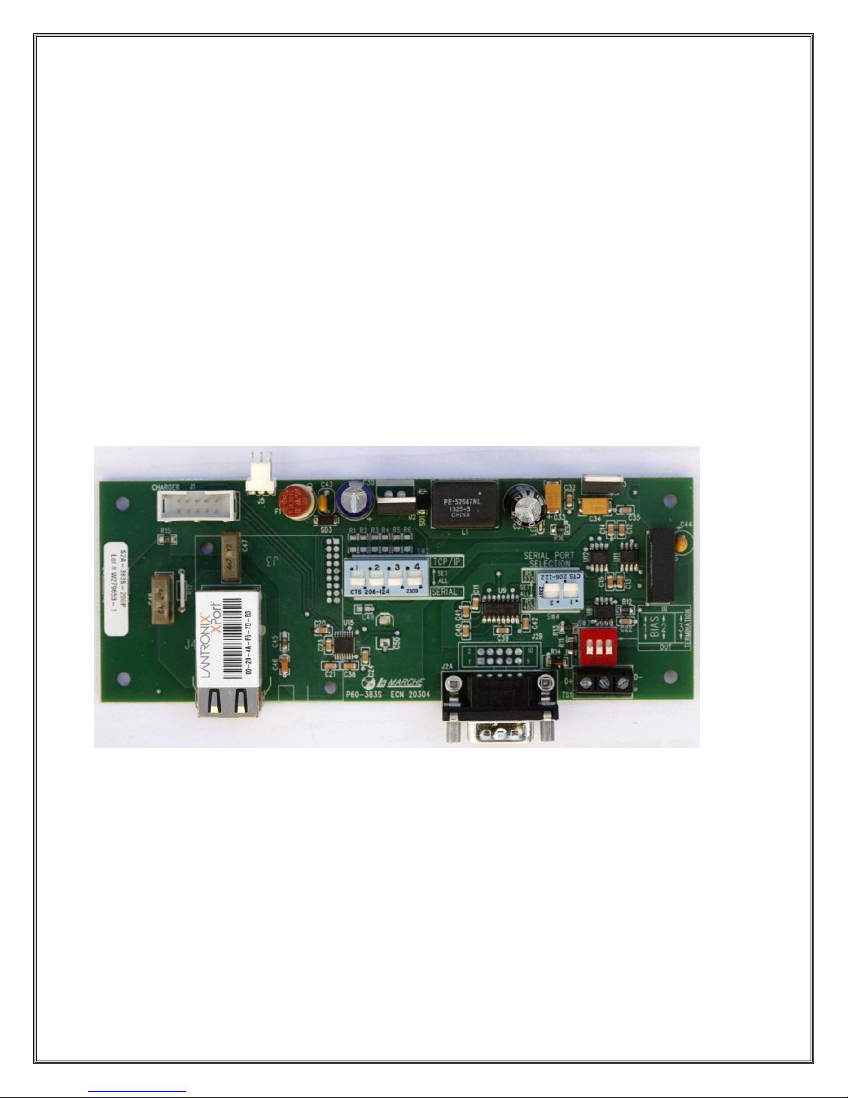
The communications card may be configured for RS232, RS485 or TCP communications.
SW2 configures the board for either Serial or TCP/IP communications.
SW4 configures the board for either RS232 or RS485 communications.
SW3 configures the BIAS and Termination Resistor(s) when using RS485.
The photo below shows the location of the dipswitches of the communications board.
Setting the Modbus Address, Baud Rate & Parity
To change the Address, Baud Rate and Parity you need to enter the customer calibration mode where
you can choose the following;
Modbus Type: Serial or TCP
Modbus Address: 1 through 247
Modbus Baud Rate (Serial Only): 1200, 2400, 4800, 9600, 19200, 38400
Modbus Parity Type (Serial Only): NONE, ODD, EVEN
Read Only Mode: This mode does not allow any settings to be modified remotely.
Page 3
SCADA INTERFACE INSTRUCTIONS - OPTION 21Q - FOR A36D/TPSD SYSTEMS/341S
Page 3 of 10
RS232 & RS485 Serial Applications
To configure the card for Serial applications you need to configure the board’s dipswitches and set the
Address, Baud Rate and Parity as required in the customer calibration mode.
TCP/IP Applications
To configure the card for TCP/IP applications you need to configure the boards dipswitches and confirm
the Address = 1, Baud Rate = 9600 and Parity = NONE in the customer calibration mode.
You will also likely want to change the IP, Subnet and Gateway. To accomplish this please refer to the
next section.
Changing the TCPIP Settings
The RTU to TCP/IP module is set at the factory as follows:
IP Address: 192.168.0.6
Netmask: 255.255.255.0
Gateway: 192.168.0.1
TCP Port Number: 502
To change the TCPIP settings it is necessary to load and install the DeviceInstaller Software provided by
Lantronix Inc. from the following URL:
http://www.lantronix.com/device-networking/utilities-tools/device-installer.html
Once this software is installed you should reconfigure your Network Adaptor to the same subnet (see
default settings above) as the Lantronix device. Connect the device to your laptop/PC using a nullmodem for a direct connection. Use a straight through if connecting through a switch or hub. If the
device is powered when you run the DeviceInstaller it will automatically begin a search and find the
device. If DeviceInstaller is running when the device is connected the Search command on the Toolbar
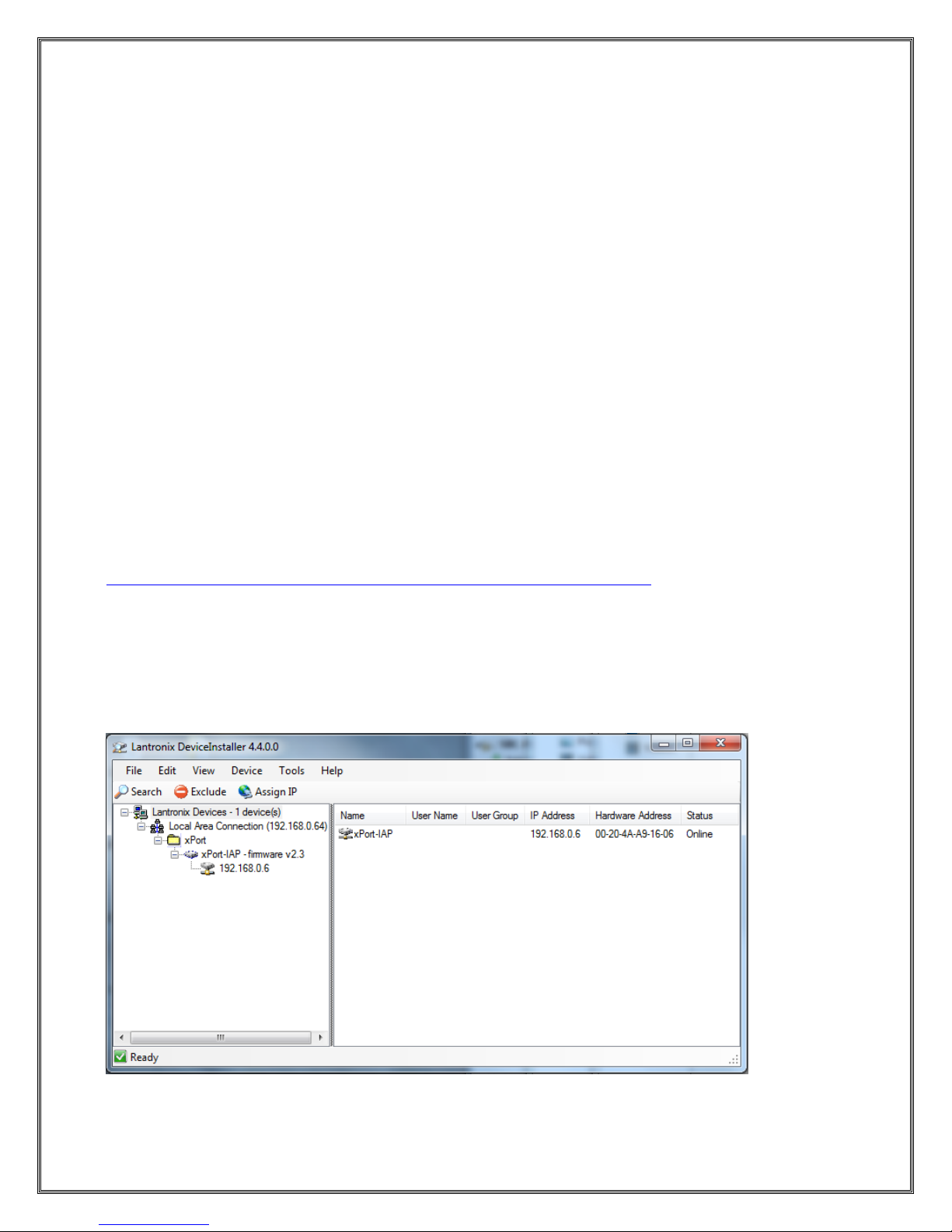
Menu will locate the device. Once the device is located, the screen should appear as pictured below.
Page 4
SCADA INTERFACE INSTRUCTIONS - OPTION 21Q - FOR A36D/TPSD SYSTEMS/341S
Page 4 of 10
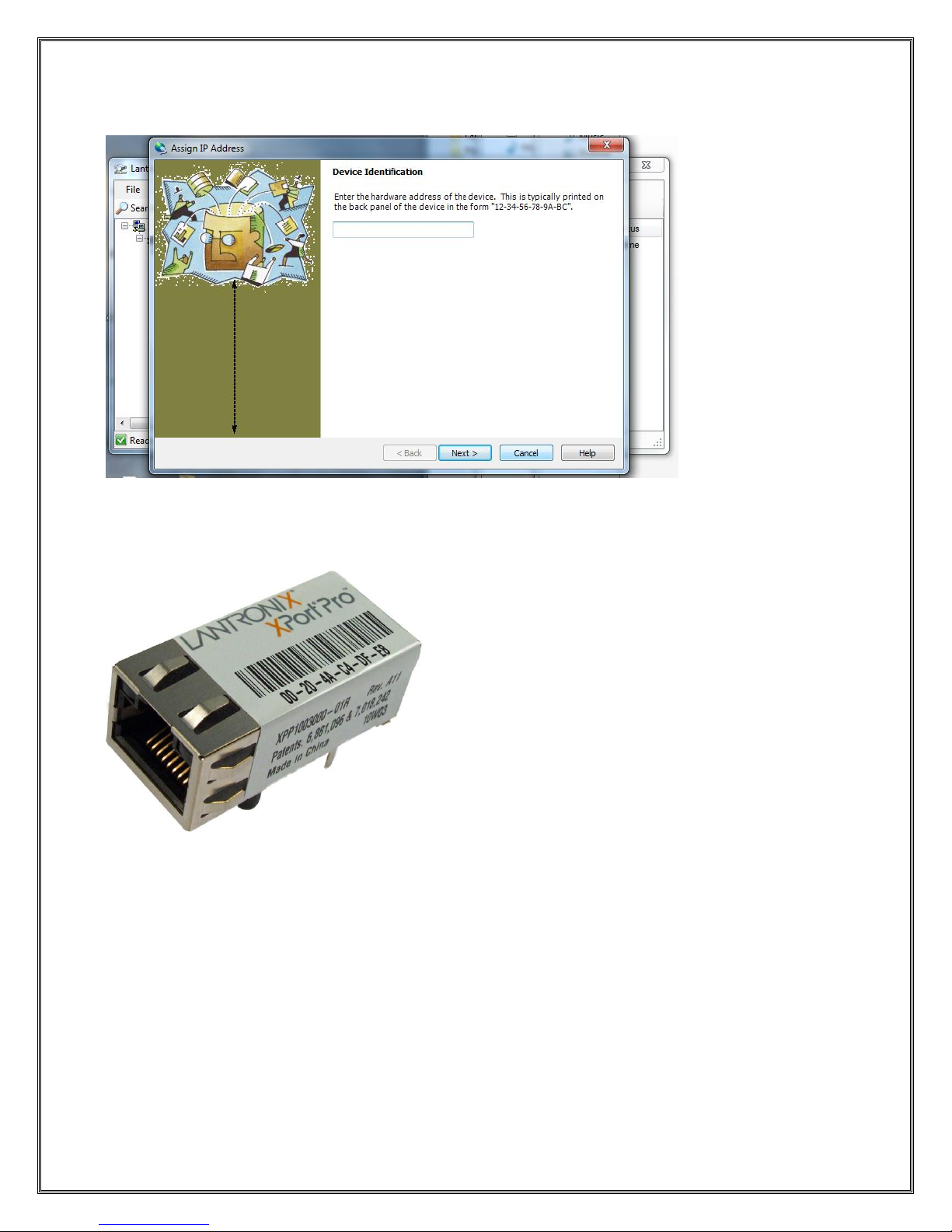
To assign the desire IP settings press the Assign IP button on the Toolbar. This will bring up the
following screen:
The Device Identification is located on the device itself as described in the dialog text above. An example
of the Lantronix device is pictured below.
In the example above the Device Identification would be 00-20-4A-C4-DF-E8. Note this is unique to each
device. After entering the ID press Next.
Page 5
SCADA INTERFACE INSTRUCTIONS - OPTION 21Q - FOR A36D/TPSD SYSTEMS/341S
Page 5 of 10
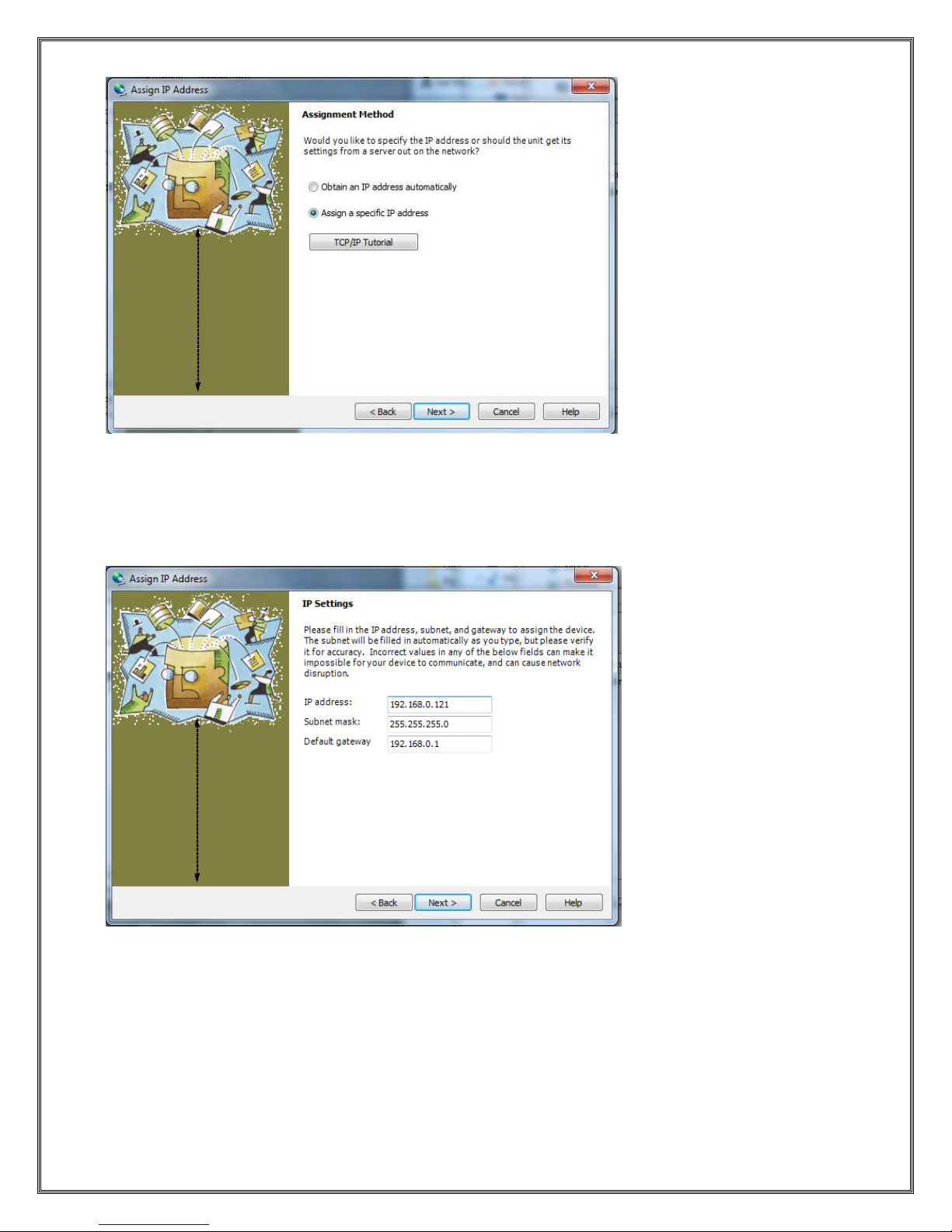
This dialog presents a choice between assigning an IP dynamically which would allow the device to
operate on a network with a DHCP server however it is recommended that a specific IP address be
assigned so it can be referenced directly on a SCADA Network.
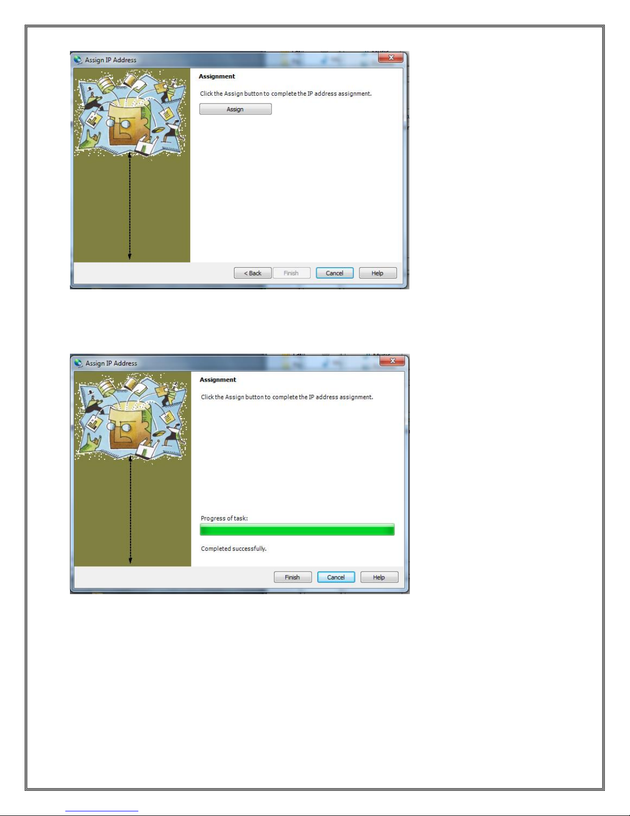
Selecting “Assign a specific IP address” will bring up the following dialog:
Enter your desired IP settings and press Next.
Page 6
SCADA INTERFACE INSTRUCTIONS - OPTION 21Q - FOR A36D/TPSD SYSTEMS/341S
Page 6 of 10
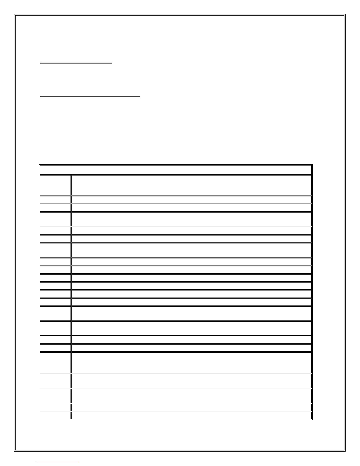
Pressing Assign will start the process of programming the device to the new IP Settings.
A progress bar and Status will appear indicating a successful operation as shown below:
Pressing Finish will complete the IP setting change process. The DeviceInstaller Application can now be
closed.
Page 7
SCADA INTERFACE INSTRUCTIONS - OPTION 21Q - FOR A36D/TPSD SYSTEMS/341S
Page 7 of 10
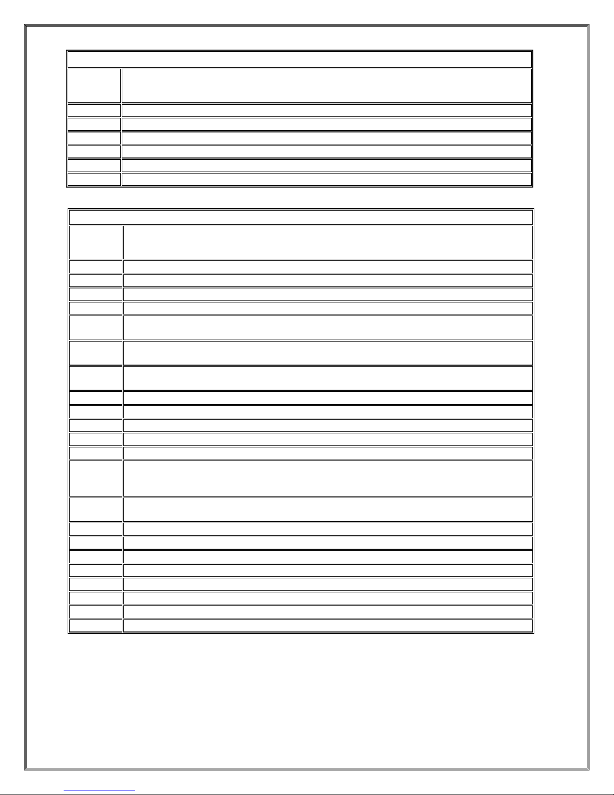
LaMarche Modbus Implementation
Supported Modbus Types
RTU
TCP
Supported Modbus Function Codes
01 – Read Coil Status (0X)
02 – Read Discrete Input Registers (1X)
03 – Read Holding Registers (4X)
04 – Read Input Registers (3X)
05 – Write Single Coil
06 – Write Single Register
10 – Write Multiple Coils
0F – Write Multiple Registers
01 - Coils
Address
Name/Description
00000
Float/EQ Mode Indicator (FLOAT=0, EQUALIZE=1)
00001
Temperature Compensation Enable (ENABLED=1).
00002
LCD Backlight Timeout Enable (ENABLED=1)
This has no effect on Chargers equipped with VFD Displays.
00003
Include Low Current Alarm in Summary Alarm (INCLUDED=1)
00004
Include AC Alarm in Summary Alarm (INCLUDED=1)
00005
Include Ground Detection Alarms in Summary Alarm (INCLUDED=1). TPSD ONLY.
For A36D this point will always read 0 and writes to are prohibited.
00006
Include Over Temperature Alarm in Summary (INCLUDED=1)
00007
Latch Summary Alarm (YES=1)
00008
Latch AC Fail Alarm (YES=1)
00009
Latch Low Voltage Alarm (YES=1)
00010
Latch High Voltage Alarm (YES=1)
00011
Latch High Voltage Shutdown Alarm (YES=1)
00012
Latch Positive Ground Alarm (YES=1). TPSD ONLY.
For A36D this point will always read 0 and writes to are prohibited.
00013
Latch Negative Ground Alarm (YES=1). TPSD ONLY.
For A36D this point will always read 0 and writes to are prohibited.
00014
Latch Overload Alarm (YES=1)
00015
Latch End of Discharge Alarm (YES=1)
00016
Reset Alarms (YES=1)
Write a “1” to reset alarms. After alarms are reset software in the controller sets this
point to “0”.
00017
Ground Detection Alarm Enable. (ENABLED=1, DISABLED=0) TPSD ONLY.
For A36D this point will always read 0 and writes to are prohibited.
00018
Test All Alarm Contacts (BEGIN TEST=1, END TEST=0). Note the HVSD alarm contacts
are not tested remotely.
00019
Test Negative Ground Contacts (BEGIN TEST=1, END TEST=0). TPSD ONLY.
00020
Test High Voltage Alarm Contacts (BEGIN TEST=1, END TEST=0).
Page 8
SCADA INTERFACE INSTRUCTIONS - OPTION 21Q - FOR A36D/TPSD SYSTEMS/341S
Page 8 of 10
01 - Coils
Address
Name/Description
00021
Test Low Voltage Alarm Contacts (BEGIN TEST=1, END TEST=0).
00022
Test Positive Ground Contacts (BEGIN TEST=1, END TEST=0). TPSD ONLY.
00023
Test AC Alarm Contacts (BEGIN TEST=1, END TEST=0).
00024
Test Summary Alarm Contacts (BEGIN TEST=1, END TEST=0).
00025
Test Low Current Alarm Contacts (BEGIN TEST=1, END TEST=0).
00026
Test Open DC Protection Alarm Contacts (BEGIN TEST=1, END TEST=0). A36D ONLY.
02 - Discrete Inputs
Address
Name/Description
10000
AC Alarm Indicator (FAILURE=1)
10001
High Voltage Alarm Indicator (FAILURE=1)
10002
High Voltage Shutdown Alarm Indicator (FAILURE=1)
10003
Low Current Alarm Indicator (FAILURE=1)
10004
Open DC Protection Alarm Indicator (FAILURE=1) A36D ONLY.
For TPSD this point will always read 0.
10005
Positive Ground Alarm Indicator (FAILURE=1). TPSD ONLY.
For A36D this point will always read 0.
10006
Negative Ground Alarm Indicator (FAILURE=1). TPSD ONLY.
For A36D this point will always read 0.
10007
Summary Alarm Indicator (FAILURE=1)
10008
End of Discharge Alarm Indicator (FAILURE=1).
10009
Overload Alarm Indicator (FAILURE=1)
10010
Over Temperature Alarm Enable (ENABLED=1)
10011
Over Temperature Alarm Status (FAILURE=1)
10012
Charger in Settings Menu (Set to 1 when charger is manually put into the settings menu
through the front panel) Remote setting changes are disabled when this is set to 1 until
the local operator exits the Settings Menu.
10013
SCADA Read Only Mode (ENABLED=1). Setting changes are not allowed when the
charger is in the settings menu or when the SCADA Read Only Mode has been selected.
10014
Negative Ground Alarm Relay Contacts (CLOSED=1, OPEN=0). TPSD ONLY.
10015
High Voltage Alarm Relay Contacts (CLOSED=1, OPEN=0).
10016
Low Voltage Alarm Relay Contacts (CLOSED=1, OPEN=0).
10017
Positive Ground Alarm Relay Contacts (CLOSED=1, OPEN=0). TPSD ONLY.
10018
AC Fail Alarm Relay Contacts (CLOSED=1, OPEN=0).
10019
Summary Alarm Relay Contacts (CLOSED=1, OPEN=0).
10020
Low Current Alarm Relay Contacts (CLOSED=1, OPEN=0).
10021
Open DC Protection Alarm Relay Contacts (CLOSED=1, OPEN=0).
Page 9
SCADA INTERFACE INSTRUCTIONS - OPTION 21Q - FOR A36D/TPSD SYSTEMS/341S
Page 9 of 10
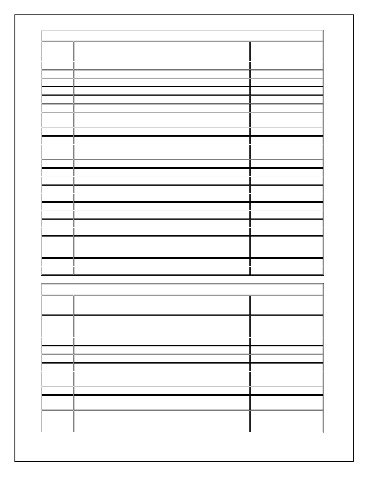
03 - Holding Registers
Address
Description, Units, Valid Settings/Range
Scale Factor
40000
Equalize Timer Mode (0,1 2,3,4)
None
40001
Equalize Timer Setting (0 to 144)
None
40002
Low Voltage Alarm Threshold, Volts, (0 to MAXAV)
0.1
40003
High Voltage Alarm Threshold, Volts, (0 to MAXAV)
0.1
40004
High Voltage Shutdown Alarm Threshold, Volts, (0 to MAXAV)
0.1
40005
Low DC Current Alarm Threshold, Amps, (0 to MAXAI)
0.1
40006
Low DC Current Alarm Recovery Threshold, Amps (Low DC
Current Alarm Threshold to MAXAI)
0.1
40007
Low Voltage Alarm Recovery Threshold, Percent (0 to 20)
None
40008
Low Voltage Alarm Delay, Seconds, (1 to 300)
None
40009
Equalize Timer Mode 4 (Auto Equalize on LV Alarm Recovery)
Delay, Seconds (1 to 300)
None
40010
High Voltage Alarm Delay, Seconds, (1 to 300)
None
40011
High Voltage Alarm Recovery Threshold, Percent (0 to 20)
None
40012
High Voltage Shutdown Alarm Delay, Seconds, (1 to 300)
None
40013
Low Current Alarm Delay, Seconds, (1 to 300)
None
40014
End of Discharge Alarm Threshold, Volts, (0 to MAXAV)
0.1
40015
End of Discharge Alarm Recovery Threshold, Percent (0 to 20)
None
40016
Overload Alarm Threshold, Amps, (0 to MAXAI)
0.1
40017
Overload Alarm Recovery Threshold, Percent (0 to 20)
None
40018
AC Alarm Delay, Seconds, (1 to 300)
None
40019
Ground Detection Alarm Delay, Seconds, (1-300) TPSD
ONLY. For A36D this point will always read 0 and writes to are
prohibited.
None
40020
End of Discharge Alarm Delay, Seconds (1-300)
None
40021
Overload Alarm Delay, Seconds (1-300)
None
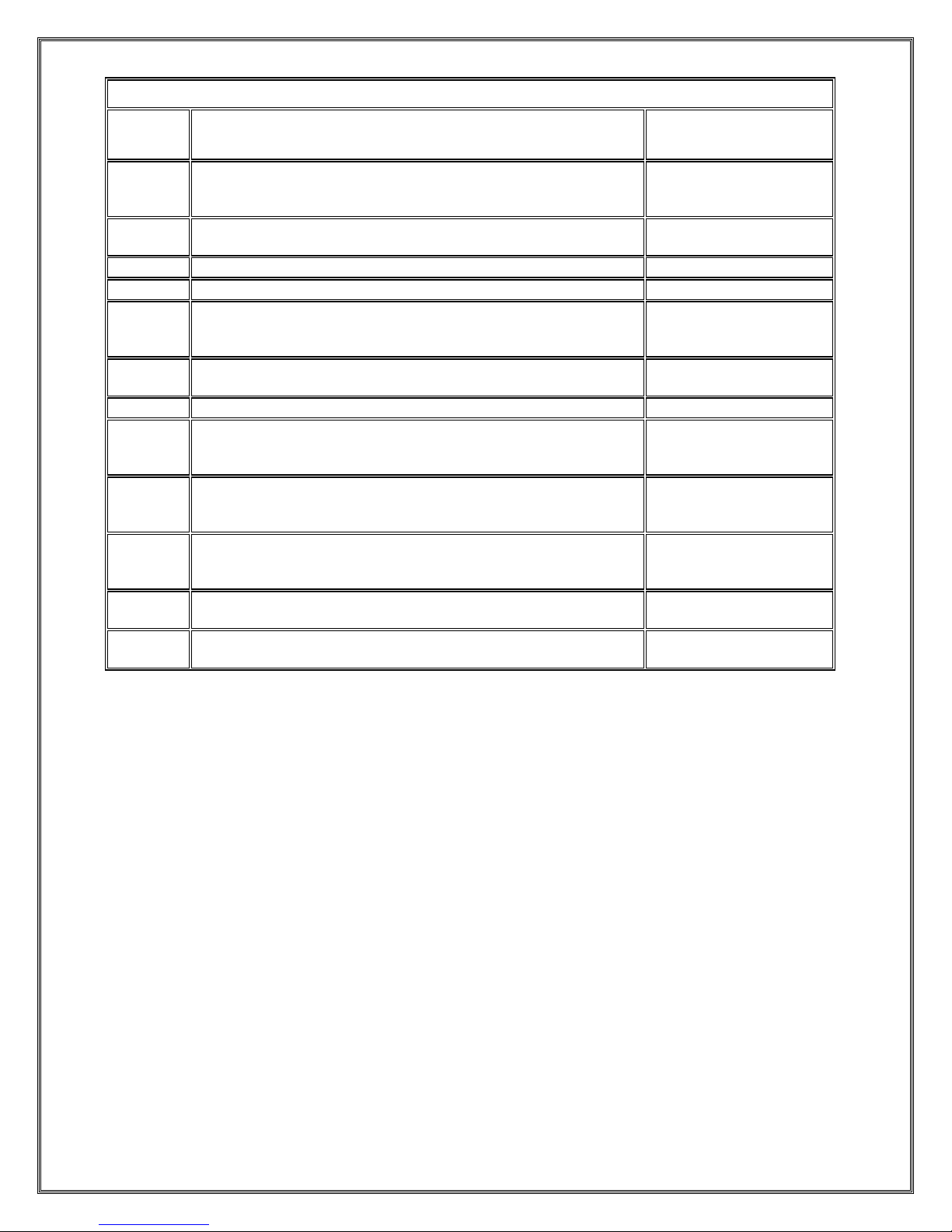
04 - Input Registers
Address
Description, Units
Scale Factor
30000
Heartbeat
This register increases once per second and may be used to
determine if communications are still occurring.
None
30001
Board Number. Will read 205 for 205T card.
None
30002
Software Version, Version of software on 205T card.
None
30003
Voltage, Volts
0.1
30004
Current, Amps
0.1
30005
Equalize Cycle Time Hours Remaining, Hours, Minutes
Note: The last two digits are the minutes.
None
30006
Auto Equalize Timer, Days
None
30007
Auto Equalize Timer, Hours, Minutes
Note: The last two digits are the minutes.
None
30008
Low DC Current Alarm Low Limit, Amps. Setting the Low DC
Current Alarm below this will result in disabling the Low DC
Current Alarm Status Indicator.
0.1
Page 10
SCADA INTERFACE INSTRUCTIONS - OPTION 21Q - FOR A36D/TPSD SYSTEMS/341S
Page 10 of 10
04 - Input Registers
Address
Description, Units
Scale Factor
30009
Local Temperature Probe Reading, Degrees C
Note: A shorted probe will give a reading of –273 and an open
probe will give a reading of+273
None
30010
Temperature Probe Status
OK=0,SHORTED=1,OPEN=2,HARDWARE FAILURE=3
None
30011
Maximum Settable Alarm Voltage, MAXAV, Volts
0.1
30012
Maximum Settable Alarm Current, MAXAI, Amps
0.1
30013
Over Temperature Probe Reading, Degrees C
Note: A shorted probe will give a reading of –273 and an open
probe will give a reading of+273
None
30014
Over Temperature Probe Status
OK=0,SHORTED=1,OPEN=2,HARDWARE FAILURE=3
None
30015
Charger Series. (0=TPSD,1=A36D)
None
30016
Battery Voltage, Volts
Note: This point should only be monitored when DI 10015=1
NOT AVAILABLE= 30000, FAILED = 30001
0.1
30017
Aux Temperature Probe #1, C
Note: NOT AVAILABLE=30000, SHORTED=30001,
OPEN=30002, FAILED=30003
None
30018
Aux Temperature Probe #2, C
Note: NOT AVAILABLE=30000, SHORTED=30001,
OPEN=30002, FAILED=30003
None
30019
Low Voltage Alarm Status (0=NO ALARM,1=LOW VOLTAGE
ALARM,2=LOW BATTERY VOLTAGE ALARM)
None
30020
P60-407S Board Failure Alarm (0=N/A,1=NO ALARM,2ALARM)
None
 Loading...