


( hampion and ( logo are used raider license fi'om Champion Atldeficwear
ASSEMBLY INSTRU IONS / OI ERS MANUAL
IMPORTANT:
S._rET'£ :
SERIAL NO.
Part No. 06055
READ ALL ASSEMBLY ENSTRUCTIONS .kND SAFETY PRE(A[THONS BEFORE USLNG THIS PRODUCT. REFERENCE ALL
SAFETY GUIDELLNES AND X__Aa_NING LABELS. RETALN PRODUCT LITERAT[_E FOR FI_RE REFERENCE.
PROPERLY W._'_i [_._ND STRETCH BEFORE EXERCISENG. IF YOU FEEL P.A1N OR DIZZINESS AT A_N_"TEXIE X_IILE
EXER(]SLNG, STOP E_iMEDL_TELY AND (ONSULT YO[_ PI_'SIC[_N.
PURCHASE DATE:
Revision: A Date: 09/05

PAGE 1 TABLE OF CONTENTS
C44F
Reference Information
Assembly Prep & Intro
Parts Listing
Hardware Chart
Product Exploded Vi
Product AssembJ_ _
Co mp u ter Op e
Troubleshooting
Preventative Maintenance
Product Registration
Pa e
2
3
4
5
6-13
14-18
19
20
21
22
__ANT _CAU_ONS
WARNING: To reduce the risk of injury, please read the following precautions befol_eassembling or using this product.
1. It is the responsibility of the owner to ensure that all itsers of this equipment are adequately informed of stated pl_ecaution_
2. Read allinstl_ctions and enclosed literatm-e carefully. Understand the assembly and operation before using the equipment.
3. Use equipment on a flat level surface. Use adjustment levelers on the bottom of equipment to help stabilize unit.
4. It's recommended to place an exercise / product mat beneath the equipment for added protection of floors or eaq0ets.
5. Keep childl_en& pets away fi'om equipment at alltimes. Unplug equipment for added safety while not in use.
6. Inspect product on a fi_quent basi_ Tighten lose assemblies or hardwm_e as needed. Replace wol3a or damaged parts.
7. This equipment is intended forinternal home use only. Do not use in a non-residential envh-anment.
Use in non- recommended envh'onments can lead to serious injm$ Tand will void all related warranties & liabilities.
8. Recommended riser weight should not exceed 300 lbs.
9. Fl_equently wipe equipment down with a dampened soft cloth.
10. Observe and adhere to allwal3Mnglabels posted on equipment.
11. Properly wal_n-up and stretch before stm_ing any sta-engthta'ainingor cm-dio exercise routine.
12. If you feel pain or dizziness at any time while exel_cising, stop immediately and consult your physician.
Safety Wm'uing: Before stmling an exercise program, consult yore- physician. This is especially impol_ant for individuals over th_
age of 35 or persons with pre-existing health problems. It's impolSani to _ead all insta'ucfions earefimy. We assume no responsibil_
ity for personalinjui_7 or consequential damages sustained by or through the use of this equipment. Additional terms & condi-
tions m_ listed in the back of this manual or enclosed owners manual.
ASSEMBLYPREP & INTRO. PAGE 2
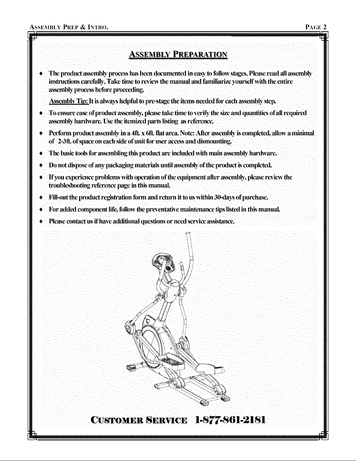
ASSEMBLY PREPARATION
€ The product assembly proeess has been documented in easy to follow stages. Please read all assembly
instructions carefully. Take time to review the manual and familiarize yore'self with the entire
assembly process before proceeding.
Assembly Tip: It is always helpful to pre-stage the items needed for each assembly step.
€ To ensm'e ease of product assembly, please take time to verify the size and quantities of all required
assembly hardware. Use the itemized parts listing as reference.
€ Perfol_ product assembly in a 4ft. x 6ft. fiat area. Note: After assembly is completed, allow a minimal
of 2-3ft. of space on each side of unit for user access and dismounting.
€ The basic tools for assembling this product are included with main assembly hardware.
€ Do not dispose of any packa_g materials until assembly of the product is completed.
€ If you experienee problems with operation of the eqm'pment after assembly, please revl'ew the
troubleshooting reference page in this manual.
€ Fill-out the product regis_ation form and retm_a it to us within 30-days of purchase.
€ For added component life, follow the preventative maintenance tips listed in this manual
€ Please contact us if have additional questions or need service assistance.
CU ii SER_[CE 1-877-861-2181

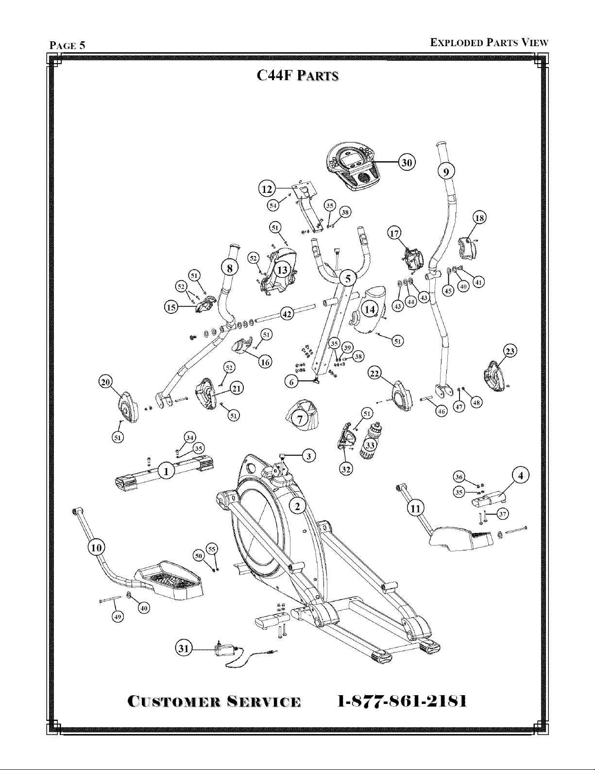
PAGE 3 PARTS REFERENCE
C44F PARTS LISTING
Item Part Description QTY,
i 23110 Front Stabilizer Assembh, 1
2 NA Base Assembly 1
3 12059 Lower Data Cable 1
4 05183 Stabilizer Extension Assembly 2
5 23107 Handlebar Mast Assembly 1
6 11025 Upper Data Cable 1
7 07125 Shroud Boot 1
8 13107 Pivot.M'm Assembly (Left) 1
9 13108 Pivot Arm Assembl) (Right) 1
10 23114 Pedal Arm Assembl3 (Left) 1
11 23115 Pedal Arm Assembly (Bigh0 1
12 23140 Computer Monnlhlg Bracket 1
13 07124 Upper Mast Cover (Rear) 1
14 07123 Upper Mast Cover _ront) 1
29 07116 0_reinstaned) Roller ( over (Right) 2
30 10027 (omputer 1
31 14001 A( Adapter 1
32 31001 Bottle Cage 1
33 31010 Sports BottJe 1
34 01003 Button Head .Mien Bolt MSx 1.25 x 16 Length 2
35 01385 Flat Washer 8 x 19 x 2t 2
36 01015 Aconl Nut M8 4
37 01372 Hex Boft M8 x 125 x 50 Length 4
38 01003 Button Head .Mien Bolt M8 x 1.25 x 16 Length 10
39 01380 Spring (Lock) _sher 7
40 01382 FLatVVasher 10 x 26 x 2t 4
41 01030 Hex Head Flange Bolt M8 x 1.0 x 20 Length 2
42 11026 Thread Pivot Shaft 17 x 385 Length 1
15 07109 Upper (Left) Rear Pivot (over 1
16 07110 Upper (Left) Front Pivot (over 1
17 07122 Upper (Righ0 Rear Pivot Cover 1
18 07121 Upper (Right) Front Pivot Cover 1
19 12060 Heart Rate Cable Assembly 1
20 07111 Lower (Left) Rear Pivot Cover 1
21 07112 Lower (Left) Front Pivot Cover 1
22 07119 Lower (Righ0 Rear Pivot Cover 1
23 07120 Lower(Right) Pivot(over 1
24 07113 0_reinstalled) Roller Arm Pivot Cover (Top / Left) 1
25 07114 _reinstalled) Roller Arm Pivot (over (Bottom / Left) 1
26 07118 0_reinstalled) Roller Arm Pivot Cover (Top / Right) 1
27 07117 (l:h'einstalled) Roller Arm Pivot (over (Bottom / Right) 1
28 07115 0_rehistalled) Roller Cover (Left) 2
43 01328 Flat _sher 17.5 x 25.3t (Black) 4
44 01051 _ ave Washer 17.5 x 25 3t (Black) 2
45 01347 Teflon _%sher 2
46 0 t 384 Button Head .Mien Bolt M8 x 1.25 x 75 Length 2
47 01383 Flat X_ asher 8x 16x It 2
48 01023 Nylon Nut M8 2
49 0 t 386 Button Head .Mien Bolt 3/8 x 128 Length 2
50 01326 Flat Washer 10 x 18 x it 2
51 0 t 043 Truss Screw M5 x 14 Length (Black) 22
52 01337 Self-threadhlg Tlaiss Screw M3 x 14 Length 18
53 0 t336 Self-threadhlg Tlaiss Screw M3 x 25 Length 2
54 0 t323 Truss Screw _L_ x .8 x 12 Length (Black) 4
55 01327 N)'lon Nut 2

HARDWARE CHART PAGE 4
C44F HARDWARE REFERENCE
D
®
BoxSpanner(2)
@
@
©
@
Allen Key(l)
®
®
@
NOTE: Most of the listed assembly hardware has been packaged separately, but some hardware items have been
preinstalled in the identified assembly parts. In these instances, simply remove and reinstall the hardware as
assembly is required. Please reference the individual assembly steps and make note of all preinstalled hardware.
PAGE 5 EXPLODED PARTS VIEW
C44F PARTS
C|,_S_TOMER SERVlCE I-S 77-$61-21S1
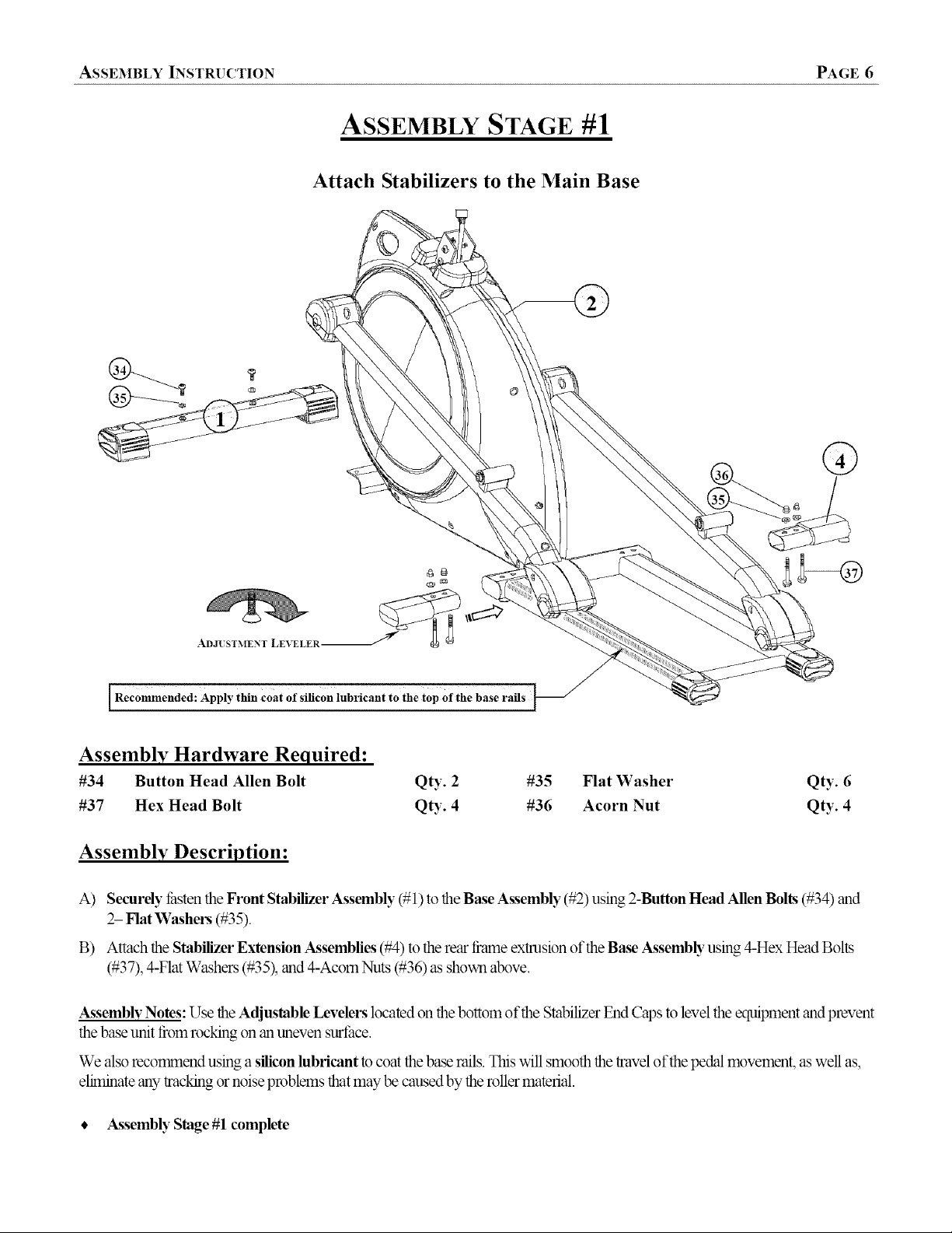
ASSEMBLY INSTRUCTION PAGE 6
ASSEMBLY STAGE #1
Attach Stabilizers to the Main Base
l Recommended: Apply thin coat of silicon lubricant to the top Of the base rails
Assembly Hardware Required:
#34 Button Head Allen Bolt Qty. 2 #35 Flat Washer
#37 Hex Head Bolt Qty. 4 #36 Acorn Nut
Qty. 6
Qty. 4
Assembly Description:
A) Securely _hstenthe Front Stabilizer Assembly (#1) to the Base Assembly (#2) using 2-Button Head Allen Bolts (#34) and
2- Flat Washers (#35).
B) Attach the Stabilizer Extension Assemblies (#4) to the rear flame extrusion of the Base A_ssembb"using 4-Hex Head Bolts
(#37), 4-Flat Washers (#35), and 4-Acom Nuts (#36) as shown above.
Assembly Notes: Use the Adjustable Levelers located on the bottom of the Stabilizer End Caps to level the equipment and prevent
the base unit from rocking on an uneven surthce.
We also recorrnnend using a silicon lubricant to coat the base rails. This will smooth the travel of the pedal movement, as well as,
eliminate any tracking or noise problems that may be caused by the roller material.
• A_ssemblyStage #1 complete

PAGE 7 ASSEMBLY INSTRUCTION
ASSEMBLY STAGE #2
Attach Handlebar Mast to the Main Base
IFigure #1
Be Careful Not to Pinch Cables ]
During Assembly ]
®
[ Hardware Preinstalled in Frame I
Assembly Hardware Required:
#35 Flat Washer*
#38 Button Head Allen Bolt*
Assembly Description:
A) Remove the preinstalled mounting hardware from the Base Assembly (#2). Slide the Shroud Boot (#7) over the Handlebar
_MastAssembly (#5). Assembly Note: For easier assembly tape the boot in place in the upper area of the mast.
B) Connect the Upper Data Cable (#6) to the Lower Data Cable Assembly (#3) as shown inFigure 1.
C) Tuck the cable lengths inside the flame tubes and slide the Handlebar Mast Assemb b"(#5) down onto the Base Assemb b"
(#2). Align the mounting holes and secure the mast assembly in place using 7-Button Head Allen Bolts (#38), 7-Spring /
Lock Washers (#39), and 7-Flat Washers (#35) as shown.
• Assembly Stage #2 completed
(*Hardware may be pveinstalled inthe BaseAssembly)
QD:. 7 #39 Spring (Lock) Washer*
Qty. 7
Qty. 7
 Loading...