

Lakeside Foodservice V6212 Installation Manual
OVAL
Ingenuity on Wheels
TM
ADJUSTMENT INSTRUCTIONS
For Models
V6210, V6211, V6212, V6213, V6214
Refer to pictures at right before starting.
WEIGHT ADJUSTMENT
Dish diameter and weight determine how many springs should
support your dishes. To insure smooth operation, use an equal
number of springs on both sides of the dispenser. Always
unhook lower end of springs only. Leave unused springs hang for
future use.
Use the following chart as a guide to determine approximately how
many springs to use.
Dish Size Springs Required
9¾” to 10½” Long 6 to 10
10¾” to 11½” Long 8 to 14
11¾” to 12½” Long 10 to 15
12¾” to 13½” Long 12 to 16
13¾” to 14½” Long 14 to 18
a. Place ten dishes into the unit directly on top cap.
b. If the dishes are above the top of the dish guides, one or more
of the springs must be unhooked. Remove the dishes, lift
the dispenser mechanism (with springs) out of the cabinet
high enough for access to the bottom of the springs, or
lift the dispenser out and place on oor.
c. Unhook one or more springs from the bottom. Leave the
spring hang for future use. Replace the ten dishes. Repeat this
operation if the dishes are still too high. Place dispenser back
into cabinet.
c. If the dish height is too low, remove all the dishes. Lift the
dispenser out of the cabinet high enough for access to
the bottom of the springs. Hook one or more loose springs
into position. Replace the dishes. Repeat this operation if the
dish height is still too low.
d. Repeat the above operations with more and with less dishes.
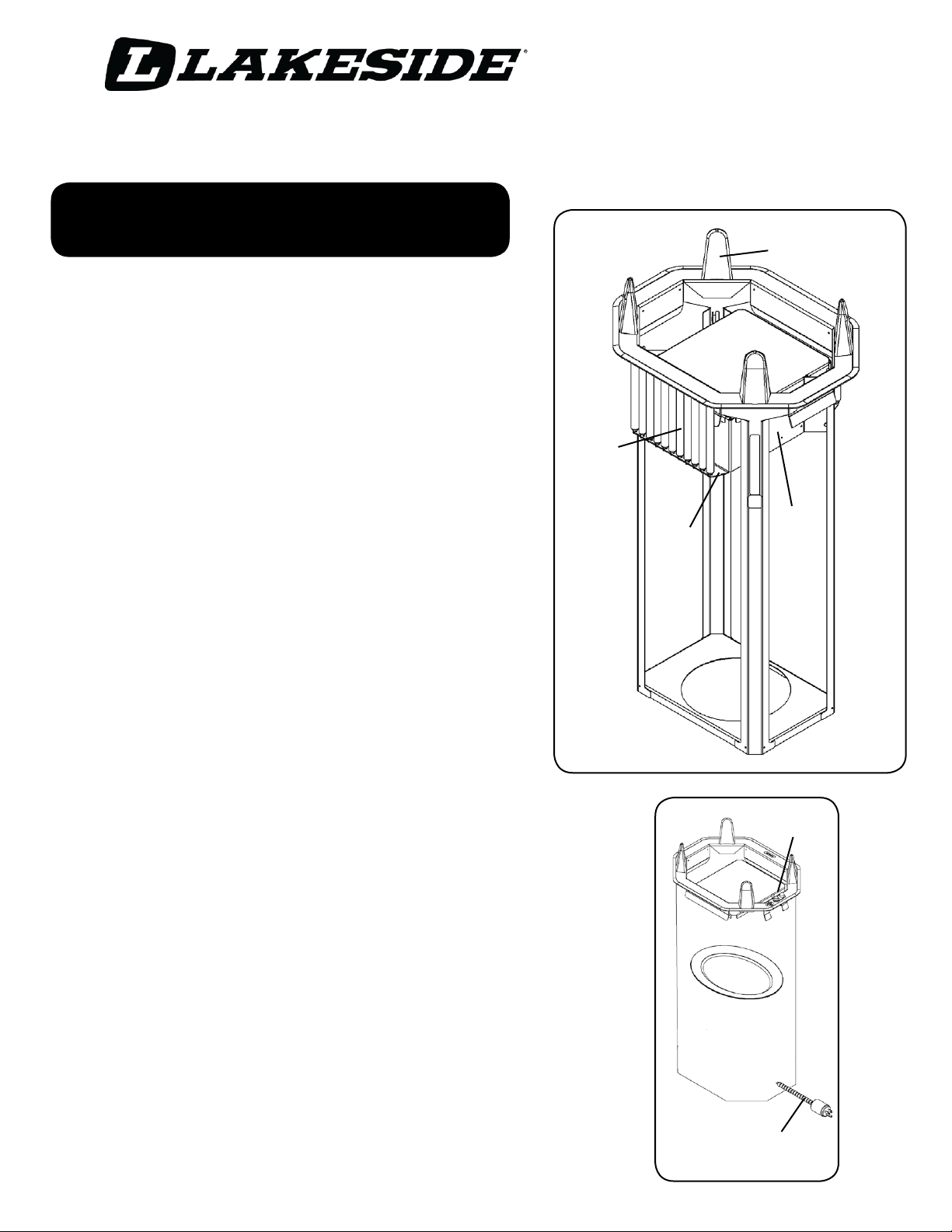
Springs
MOBILE HEATED
self-leveling
DISPENSER
Top Cap
Lower
Spring
Ring
Pilot Light
Dish Guide
Carriage
Assembly
Switch &
THERMOSTAT ADJUSTMENT
The thermostat is set for about l50°F. To obtain temperatures
above or below this:
a. Remove self-leveling mechanism from tube.
b. Turn knob located on inside of tube. Temperature range of
thermostat Is l00°F. To 175°F. The higher the number setting,
the higher the temperature.
ADDITIONAL INFORMATION ON REVERSE SIDE.
Flexible Electrical Conduit
With Twist -Lock Plug
OVAL
Ingenuity on Wheels
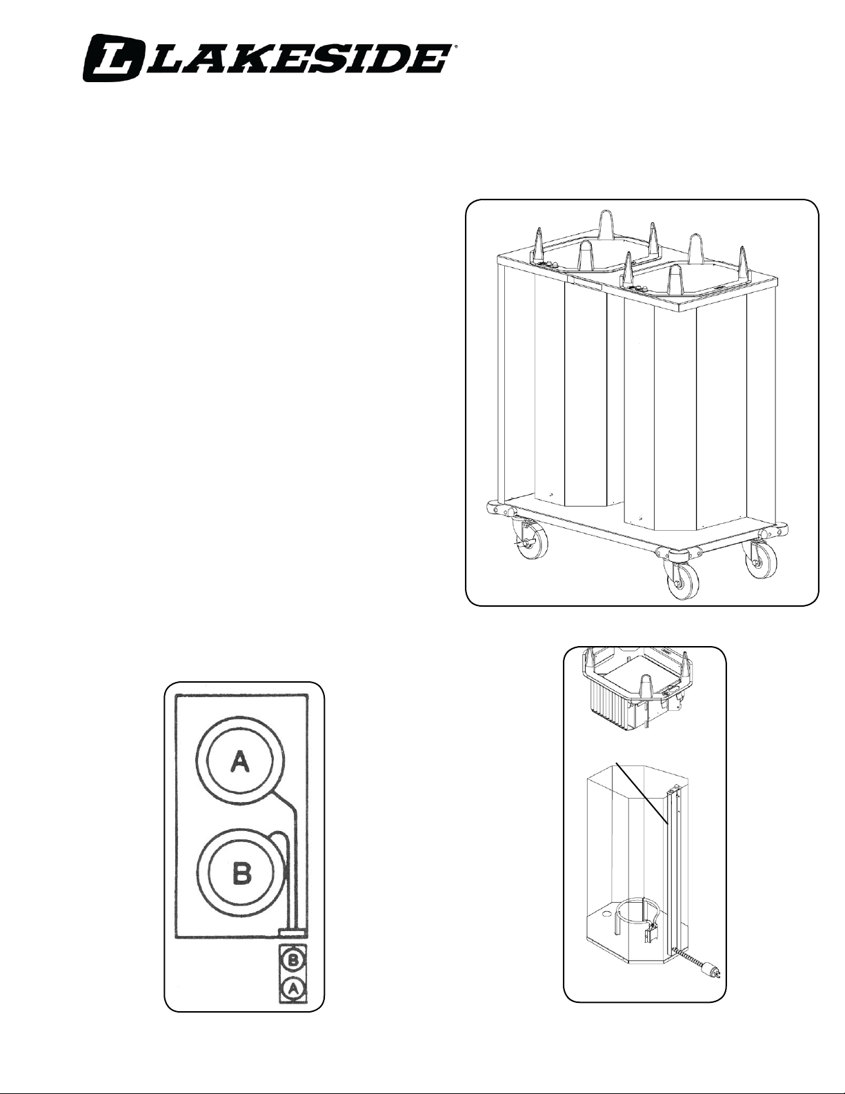
REMOVAL OF HEATED TUBES FROM CABINET
a. Unplug cart from electrical source.
NOTE: Always start by removing the heated tube which is the
closest to the electrlcal source cord.
b. Lift self-leveling mechanism (with springs) out of tube and place
on floor.
c. Lift heated octagonal tube out of the cabinet and rest on top
of cabinet.
d. Reach inside cabinet following flexible conduit to twist-lock plug.
Twist plug counterclockwise and remove from receptacle. Heated
tube may now be placed on floor.
e. Repeat above steps for other octagonal tube.
To reinstall octagonal tubes, reverse above procedure:
a. Always install the heated tube that is the further from the electrical
source cord first.
b. Place heated tube on top of cart, connect twist-lock plug to
appropiate receptacle inside cart with a clockwise motion (see
plug- in sequence diagram below), and lower tube into the cabinet.
c. Install the other tube following the insructions above.
d. After both octagonal tubes are installed, lower the seIf-leveling
mechanisms into tubes.
TM
MOBILE HEATED
self-leveling
DISPENSER
CLEANING OF UNIT
a. Unplug unit from electrical source.
b. Lift self-leveling mechanism from square tube and clean as desired.
c. Remove octagonal tube with heating mechanism from mobile
cabinet.
d. Wash inside and outside of outside of tube with a damp cloth. Do
not submerge tube, which contains the heating rod, in liquid or run
through dishwasher.
e. Wash inside and outside of cabinet with a mild soap and water.
Dry thorougly.
JUNCTION
PLUG-IN
SEQUENCE
Thermostat
Dial
For more information, call Lakeside Customer Service at 800.558.8565
Email: info@eLakeside.com www.eLakeside.com
 Loading...