

Lakeside Foodservice 757 Installation Manual
Installation, Maintenance, & Repair
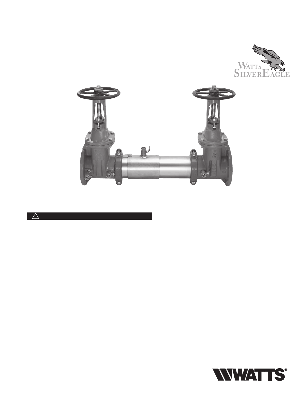
Series 757, 757DCDA & LF757DCDA
Double Check Valve Assemblies
Double Check Detector Assemblies
Sizes: 21⁄2" – 10" (65 – 250mm)
RP/IS-757/757DCDA
®
757 OSY
WARNING
!
You are required to thoroughly read all installation instructions
and product safety information before beginning the installation of this product. FAILURE TO COMPLY WITH PROPER
INSTALLATION AND MAINTENANCE INSTRUCTIONS
COULD RESULT IN PRODUCT FAILURE WHICH CAN
CAUSE PROPERTY DAMAGE, PERSONAL INJURY AND/
OR DEATH. Watts is not responsible for damages resulting
from improper installation and/or maintenance.
Local building or plumbing codes may require modifications to
the information provided. You are required to consult the local
building and plumbing codes prior to installation. If this information is not consistent with local building or plumbing codes,
the local codes should be followed.
Need for Periodic Inspection/Maintenance: This product
must be tested periodically in compliance with local codes, but
at least once per year or more as service conditions warrant.
Replace internal components every 5 years.
Corrosive water conditions, and/or unauthorized adjustments
or repair could render the product ineffective for the service
intended. Regular checking and cleaning of the product’s
internal components helps assure maximum life and proper
product function.
NOTE: For Australia and New Zealand, line strainers should be
installed between the upstream shutoff valve and the inlet of
the backflow preventer.
Its important that this device be tested periodically in compliance with local codes, but at least once per year or more as
service conditions warrant. If installed on a fire sprinkler system,
all mechanical checks, such as alarm checks and backflow
preventers, should be flow tested and inspected internally in
accordance with NFPA 13 and NFPA 25.
Testing
For field testing procedure, send for IS-TK-DL,
IS-TK-9A, IS-TK-99E AND IS-TK-99D.
For other repair kits and service parts, send for PL-RP-BPD.
For technical assistance, contact your local Watts
representative.

Installation Instructions
Series 757, 757DCDA & LF757DCDA
Guidelines
Most field problems occur because dirt and debris present in
the system at the time of installation become trapped in the #1
check. The system should be flushed before the backflow valve
is installed. If the system is not flushed until after the backflow
valve is installed, remove both check modules from the valve
and open the inlet shutoff to allow water to flow for a sufficient
time to flush debris from the water line. If debris in the water
system continues to cause fouling, a strainer can be installed
upstream of the backflow assembly.
Watts Series 757 and 757DCDA/LF757DCDA may be installed
in either horizontal or vertical position as long as the backflow assembly is installed in accordance with the direction of
the flow arrow on the assembly and the local water authority
approves the installation. The assembly should be installed with
adequate clearance around the valve to allow for inspection,
testing and servicing. 12" should be the minimum clearance
between the lower portion of the assembly and the floor or
grade.
NOTE: Assembly body should not be painted.
Maintenance Instructions
Horizontal Installation
Vertical
Installation
N Pattern
21/2" – 6" (65 – 150mm)
Figure A
Figure D
Prior to servicing any Watts valve, it is mandatory to shut
down the water system by closing both the inlet and outlet
shutoff valves. After shutoff valves are closed, open test
cock #2, #3 and #4 to relieve pressure within the backflow
assembly.
1. After #3 test cock has been opened to relieve pressure,
remove #3 test cock from housing. (Figure A)
2. Insert a #3 screwdriver through the hole on the top of the
cover sleeve and using both hands rotate the cover sleeve
approximately
wise to break the sleeve O-ring seals. Using the screwdriver,
slowly slide the cover sleeve to the downstream side of the
housing. (Figure B)
3. Remove the stainless steel check retainer from the housing.
(Figure B)
4. Remove the #1 check module (Figure C) by inserting two
flat blade screwdrivers into the slots on either side of the
check module and gently pry the check module toward the
open zone.
2
1
/4-turn clockwise and 1/4-turn counterclock-
Figure B
Figure E
5. Remove #2 check module with the same instructions as in
#4 above. For servicing 6" (150mm) checks see 8" – 10"
(200 – 250mm) instructions on p. 3.
6. To clean or inspect either check module, insert a #3 screwdriver through the downstream side of the check module as
shown in Figure D and E. When the screwdriver is in place,
remove the E-clip (Figure F) and pin connecting the structural members and the check clapper will open with no tension.
7. Thoroughly clean the seating area. The sealing disc may be
removed, if necessary, by removing the screws connecting
the keeper plate to the clapper. The sealing disc may be
reversed and reinstalled if the elastomer is cut or damaged.
8. Wash check module and O-ring and inspect for any damage. If damaged, reinstall new parts.
9. After thorough cleaning, lubricate O-ring w/FDA approved
lubricant, replace pin and E-clip in structural members,
remove screw driver and reinstall check modules and
assemble housing in reverse order of these instructions.
Figure C
Figure F
 Loading...