

Page 1
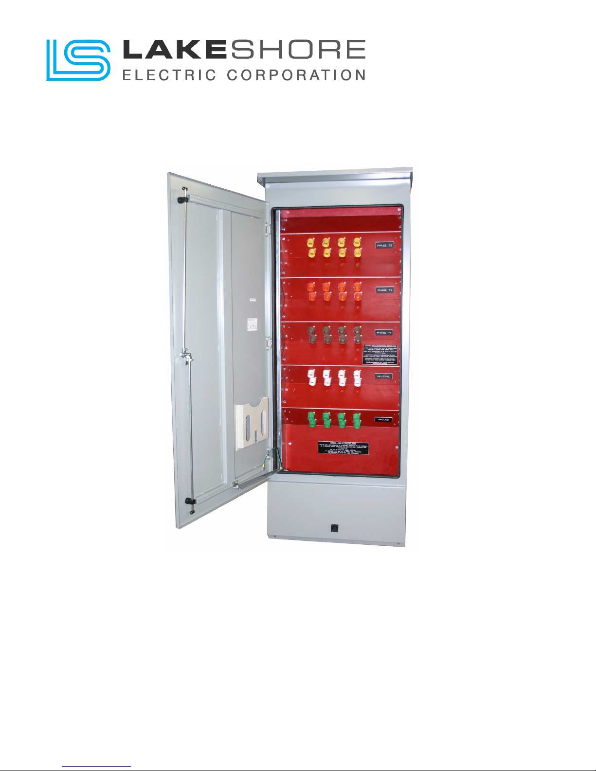
Quick Connection Cabinet (QCC)
Installation / Operation / Maintenance Manual
2000A thru 4000A Ratings, 480Vac Max
Quick Connection Cabinet – Installation/Operation/Maintenance Manual Page 1 of 4
Page 2

Quick Connection Cabinet – Installation/Operation/Maintenance Manual
WARNING!
WHEN WORKING ON EQUIPMENT OF THIS TYPE,
EXTREME DANGER OF ELECTROCUTION EXISTS
THAT MAY RESULT IN INJURY OR DEATH. DO NOT
ATTEMPT ANY REPAIRS OR ADJUSTMENTS TO THIS
EQUIPMENT WITHOUT FIRST TAKING THE
APPROPRIATE PRECAUTIONS TO PREVENT
PERSONAL INJURY AND EQUIPMENT DAMAGE.
DURING INSTALLATION AND USE OF THIS PRODUCT,
COMPLY WITH THE NATIONAL ELECTRICAL CODE
(NEC), FEDERAL, STATE AND LOCAL CODES, AND
ALL OTHER APPLICABLE SAFETY CODES.
MAIN UTILITY POWER MUST BE OFF DURING
INSTALLATION, WHEN PERFORMING EQUIPMENT
MAINTENANCE OUTSIDE THE EQUIPMENTS NORMAL
MAINTENANCE SCOPE AND WHEN PERFORMING
REQUIRED MAINTENANCE ON ANY POWER
CABLE(S) CONNECTED TO THE EQUIPMENT.
WARRANTY
Lake Shore Electric Automatic Transfer Switches are
guaranteed against defective materials and workmanship
for a period of one year from date of shipment. If, within
one year after shipment, it is proved to Lake Shore's
satisfaction that the equipment requires valid warranty
and Lake Shore is promptly notified of same, Lake Shore
will make necessary corrections, free of charge. F.O.B.
works where manufactured.
Such necessary corrections constitute the full extent of
Lake Shore's warranty. There are no warranties, which
extend beyond those described herein. This warranty is
exclusive and is in lieu of all other warranties, whether
written, oral, implied or statutory. No warranty of
merchantability or of fitness for purpose shall apply.
Lake Shore is not responsible for damage to its
equipment through improper installation or use,
unauthorized repair or modifications, or attempts to
operate it above its rated capacities or in abnormal
environments. In no event, whether as a failure to meet
conditions of the warranty or otherwise, shall Lake Shore
be liable for any special, incidental, or consequential
damages, including, but not limited to, loss of profit or
revenues, loss of good will, damages to associated
equipment, cost of capital, cost of substitute products,
facilities, service or replacement power, costs of
downtime or claims of third parties for such damages.
Quick Connection Cabinet – Installation/Operation/Maintenance Manual Page 2 of 4
Notice: The owner of this quick connection cabinet must
perform periodic maintenance as described in this manual
in order to maintain Lake Shore Electric Corporation’s one
year exclusive warranty. Failure to perform this
maintenance shall void this warranty.
NOTE
Engineering changes may have been made after
publication date. Any departure from this manual should
be checked with Lake Shore Electric Corporation.
Lake Shore Electric Corporation reserves the right to
change specifications without prior notice.
Page 3
Quick Connection Cabinet – Installation/Operation/Maintenance Manual
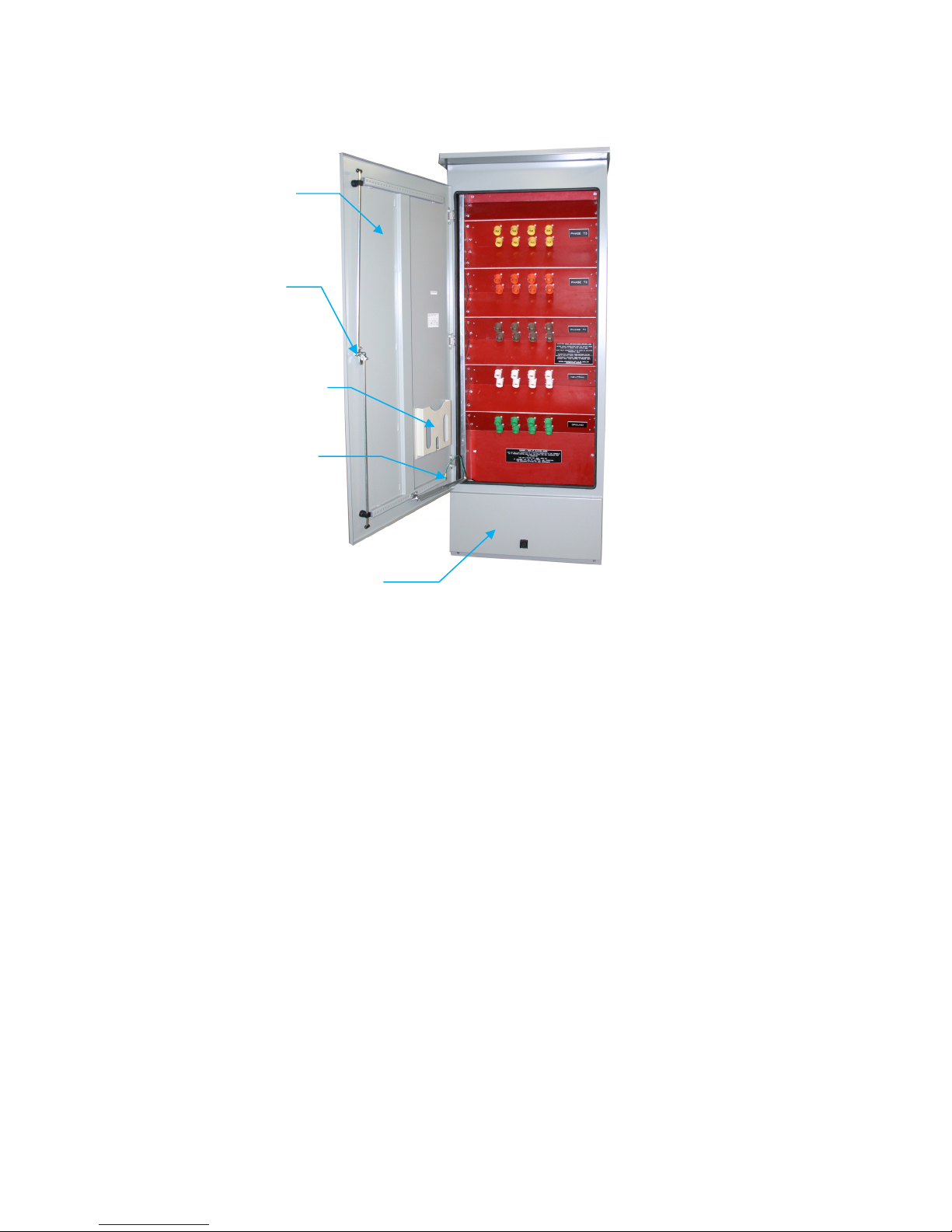
3-Point Door Latch
OVERVIEW
Lake Shore Electric’s Quick Connection Cabinets (QCC)
are intended to provide a temporary connection to an
emergency generator and a permanent connection to a
building load.
QCC INSTALLATION
IMPORTANT! When cables must be connected or
disconnected to the QCC, the generator must be “OFF”!
Once determining the appropriate size cable to connect
the QCC to the building load, conduits must enter from
either the top or rear of the cabinet. If from the rear, they
must be as close to the top as possible to allow for
adequate cable bend area. Additionally, consideration
must be given when rear connected to insure the conduit
hub does not interfere with the mounting of the cabinet.
NEVER enter conduits from the bottom or the sides of
the cabinet. In order to maintain the Nema 3R and
Nema 4 ratings, insure that appropriate gaskets and/or
seals are utilized during installation. The cabinet must
be mounted level to allow for proper drainage through
the integral weep holes located in the bottom of the unit.
Front Door
Print Pocket
Door Stop
Cam-Lok Access Door
THE STANDARD QCC PRODUCT DOES NOT
PROVIDE OVERCURRENT PROTECTION OF ANY
KIND. IT MUST BE PROTECTED BY AN UP-STREAM
CIRCUIT BREAKER TO MAINTAIN REQUIRED SHORT
CIRCUIT RATINGS.
Confirm that the generators voltage and phase sequence
match that as provided with the QCC unit. The CamLoks are color coded with voltages and phase
sequences clearly marked on a label inside the lower
access door as well as included on the Outline drawing
provided in the print pocket located inside the front door.
Minimal periodic maintenance is required other than
visual inspection to insure proper operation. Inspect
sealing of the doors and gaskets and check that the
proper torque is maintained on the compression lugs
(supplied by installer) at the load connection to the bus
bars.
The required torque values are visible on a label located
on the inside of the front door as well as on the Outline
drawing located in the print pocket.
Quick Connection Cabinet – Installation/Operation/Maintenance Manual Page 3 of 4
Page 4
Quick Connection Cabinet – Installation/Operation/Maintenance Manual
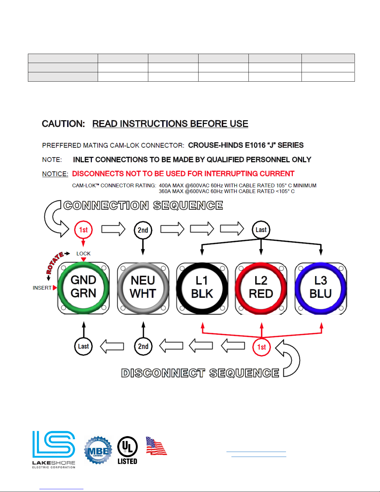
STANDARD CAM-LOK COLOR CODE BY VOLTAGE
Voltage
120/240Vac Black Red Blue White Green
277/480Vac Brown Orange Yellow White Green
L1 (A) L2 (B) L3 (C)
NEU GND
Quick Connection Cabinet – Installation/Operation/Maintenance Manual Page 4 of 4
Contact Information
p:800.225.0141
Made in the
USA
Rev: September 2018
www.lake-shore-electric.com
© 2018 Lake Shore Electric Corporation - All Rights Reserved
f:440.232.5644
Information subject to change without notice.
Location of Factory
Lake Shore Electric
205 Willis Street
Bedford, OH 44146
 Loading...