

Page 1
1 http://www.lakeshore.com/products/Gaussmeters/F71-F41-teslameters/
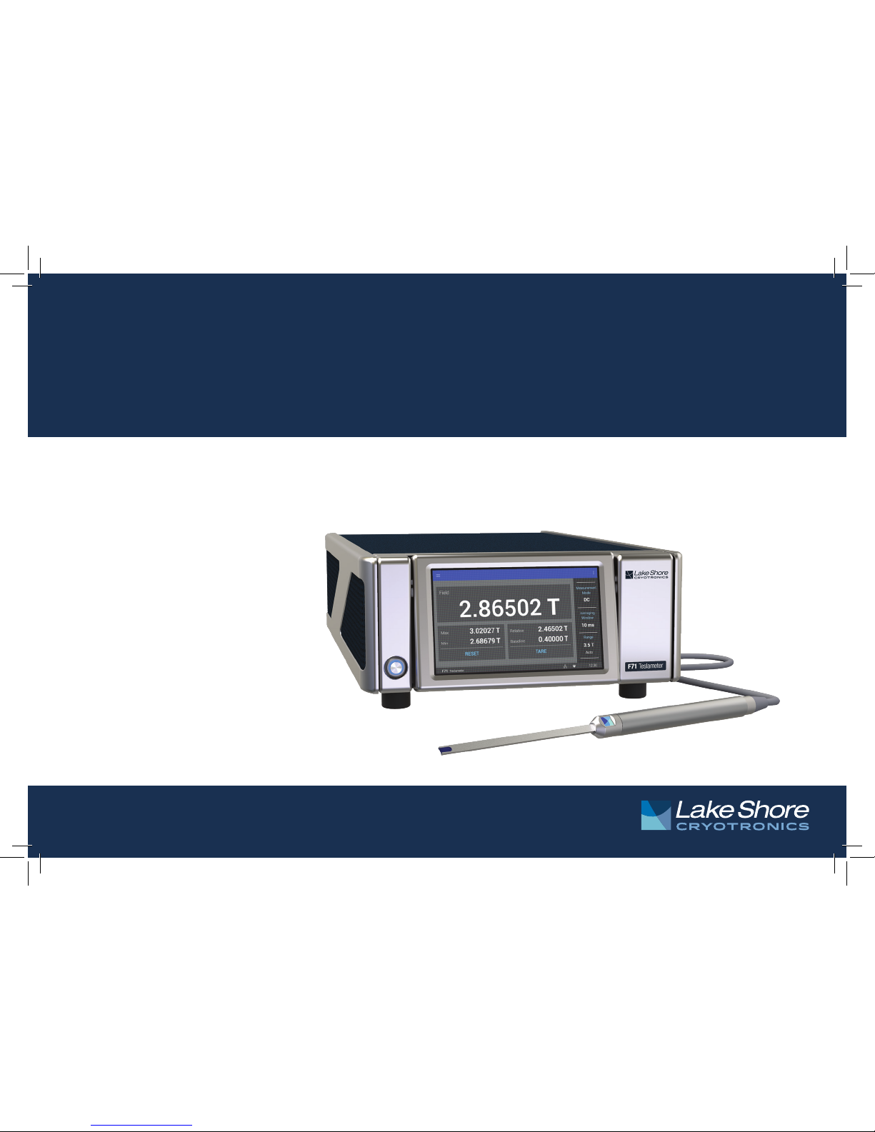
F71/F41 Teslameter Quick Start Guide
Quick Start Guide
F71 Multi-axis teslameter
F41 Single-axis teslameter
Page 2
2
F71/F41 Teslameter Quick Start Guide
Safety Precautions
Observe these general safety precautions during all phases
of instrument operation, service, and repair. Failure to comply
with these precautions or with specific warnings elsewhere in
this manual violates safety standards of design, manufacture,
and intended instrument use. Lake Shore Cryotronics, Inc.
assumes no liability for Customer failure to comply with these
requirements.
The F71/F41 teslamter protects the operator and surrounding
area from electric shock or burn, mechanical hazards,
excessive temperature, and spread of fire from the instrument.
Environmental conditions outside of the conditions below may
pose a hazard to the operator and surrounding area.
Indoor use
Altitude to 2000 m
-20 °C to 70 °C, <90% relative humidity non-condensing
Overvoltage category II
Pollution degree 2
Ground the Instrument
To minimize shock hazard, the instrument is equipped with
a 3-conductor AC power cable. Plug the power cable into an
approved 3-contact electrical outlet or use a 3-contact adapter with
the grounding wire (green) firmly connected to an electrical ground
(safety ground) at the power outlet. The power jack and mating
plug of the power cable meet Underwriters Laboratories (UL) and
International Electrotechnical Commission (IEC) safety standards.
Ventilation
The instrument has ventilation holes in its side covers. Do not block
these holes when the instrument is operating.
Do Not Operate in an Explosive Atmosphere
Do not operate the instrument in the presence of flammable
gases or fumes. Operation of any electrical instrument in such an
environment constitutes a definite safety hazard.
Keep Away from Live Circuits
Operating personnel must not remove instrument covers. Refer
component replacement and internal adjustments to qualified
maintenance personnel. Do not replace components with power
cable connected. To avoid injuries, always disconnect power and
discharge circuits before touching them.
Do Not Substitute Parts or Modify Instrument
Do not install substitute parts or perform any unauthorized
modification to the instrument. Return the instrument to an
authorized Lake Shore Cryotronics, Inc. representative for service
and repair to ensure that safety features are maintained.
Page 3
3 http://www.lakeshore.com/products/Gaussmeters/F71-F41-teslameters/
F71/F41 Teslameter Quick Start Guide
Cleaning
Do not submerge instrument. Clean only with a damp cloth and mild detergent.
Exterior only.
Desktop Installation
When installing the instrument in a desktop environment, ensure it is mounted on a
flat, level surface.
Improper Use
If the instrument is used in a manner that is not specified by Lake Shore, the safety
protections provided by the instrument are no longer guaranteed, and may be
impaired.
Child Safety
This equipment is not suitable for use in locations where children are likely to be
present.
Key specifications
Power requirement
100 V to 240 V (universal input), 50 Hz
to 60 Hz, 30 VA
Size
216 mm wide × 87 mm high ×
369 mm deep (8.5 in × 3.4 in × 14.5 in),
half rack
Weight
3.2 kg (7 lb)
Approval
CE mark, FCC, Giteki mark
Operating conditions
Rated accuracy: 18 °C to 28 °C,
<70% relative humidity non-condensing
Reduced accuracy: -20 °C to 70 °C,
<90% relative humidity non-condensing
NOTE: Not all specifications are listed.
For full specifications, see http://www.
lakeshore.com/products/Gaussmeters/F71F41-teslameters/pages/Specifications.aspx.
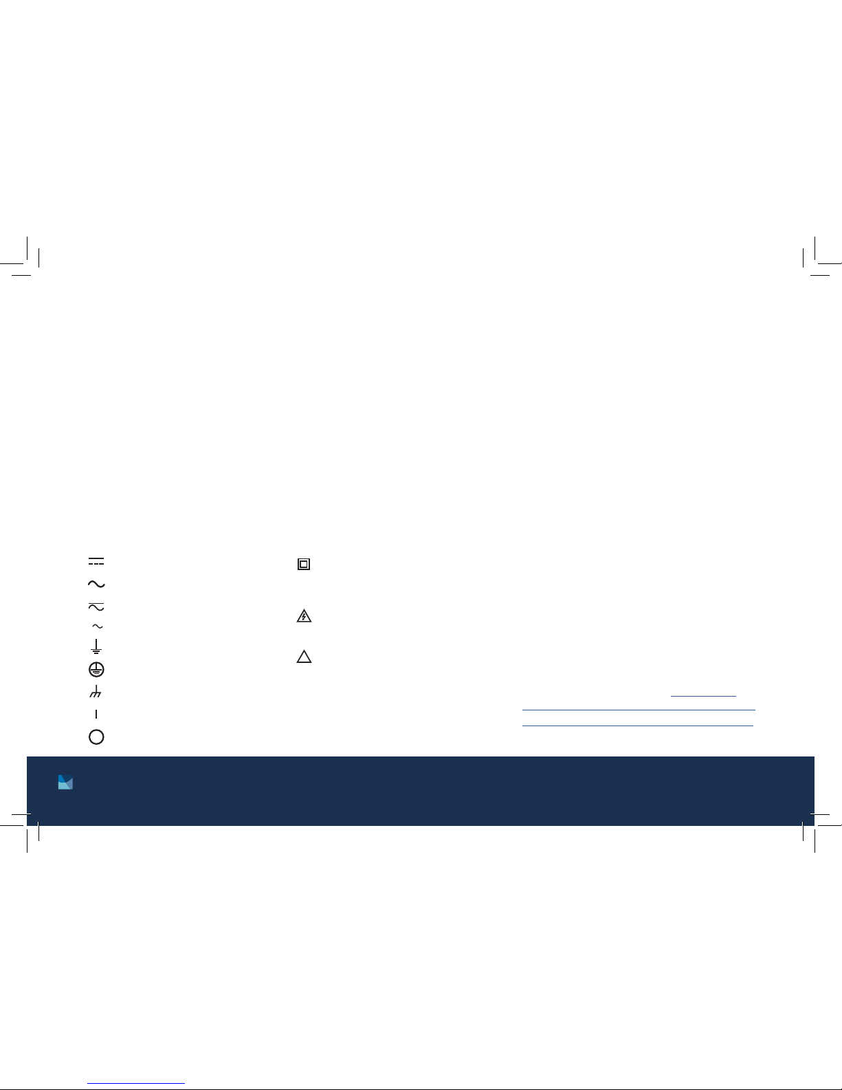
!
Direct current (power line)
Equipment protected throughout
by double insulation or reinforces
insulation (equivalent to Class II of
IEC 536—see Annex H)
CAUTION: High voltages; danger of
electric shock; background color:
yellow; symbol and outline: black
CAUTION or WARNING: See
instrument documentation;
background color: yellow;
symbol and outline: black
Off (supply)
On (supply)
Frame or chassis terminal
Protective conductor terminal
Earth (ground) terminal
3
Three-phase alternating current (power line)
Alternating or direct current (power line)
Alternating current (power line)
Page 4
4
F71/F41 Teslameter Quick Start Guide
Introduction
This guide provides basic information for getting started
with your Lake Shore F71/F41 teslameter. For further
documentation and information, see our website.
Items included with the F71/F41 teslameter:
F71/F41 teslameter
6-pin terminal block, two count
Line power cord
Wi-Fi antenna
USB A to USB-Type C™ adapter
Unpacking
1. Inspect all items for both visible and hidden damage
that occurred during shipment. If there is visible
damage to the contents, contact the shipping
company and Lake Shore immediately.
NOTE: Procedures vary with shipping companies.
Keep all damaged shipping materials and contents
until instructed to either return or discard them.
2. Keep the container and shipping materials until all
contents have been accounted for.
3. Check off each item on the packing list as it is
unpacked.
Features
The F71/F41 teslameter includes features such as:
DC and RMS measurement
Peak to peak measurement
Autoranging
Variable averaging window
Min/Max hold
Relative readings
Temperature compensation
Frequency measurement of field
TruZero™ technology to reduce measurement noise
and offset
TiltView™ touchscreen for improved viewing angles
Smaller, ultra-thin Hall sensor active areas for
improved accuracy
Multiple probe types to suit your application
Fast warm up
Isolated input and output relays
Analog Hall voltage output
3-year standard warranty
High-speed data acquisition
Field control option
USB, Ethernet and Wi-Fi connectivity
Page 5
5 http://www.lakeshore.com/products/Gaussmeters/F71-F41-teslameters/
F71/F41 Teslameter Quick Start Guide
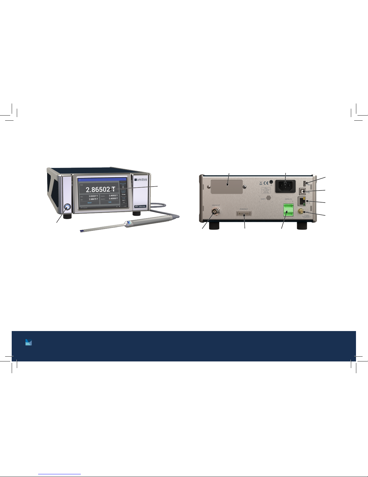
The front panel consists of:
1. Power button
2. TiltView™ touchscreen
Front panel Rear panel
The rear panel consists of:
1. Option card slot
2. Line input assembly
3. USB Type-C™ interface
4. USB serial communications interface
5. RJ-45 Ethernet interface
6. WLAN antenna connector
7. Digital I/O port
8. Probe input connector
9. BNC analog output connector
q
o i
u
y
t
r
e
w
q
w
Page 6
6
F71/F41 Teslameter Quick Start Guide
Placement
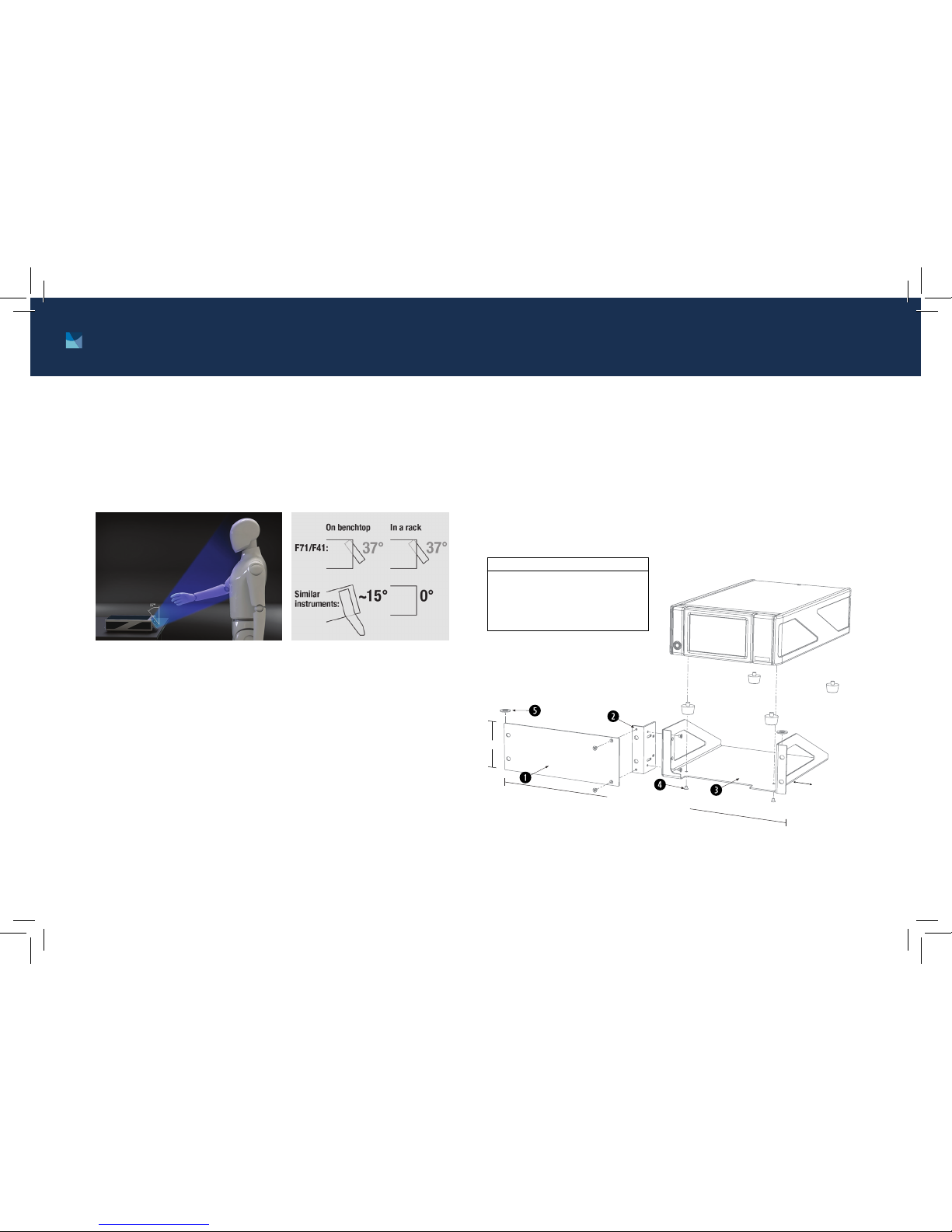
The F71/F41 teslameter is an out-of-the-box benchtop
instrument with an adjustable TiltView™ screen for an
improved viewing angle. The screen adjusts from a
0° to a 37° viewing angle, whether mounted in a rack or
on a bench top.
Rack mounting
The teslameter can be installed into a full rack or half
rack mount using the optional Lake Shore rack mount
kits (half rack mounting is shown below).
NOTE: Ensure that there is 1 in (25 mm) clearance on
both sides of the instrument after rack mounting.
Assemble the blank
panel and tray to the
rack mount ear before
mounting the tray to
the instrument
If a non-XIP full rack
instrument will be installed
above, temporarily install
supplied spacers to allow
screen to tilt freely
*A third-party shelf may be used, though more space may be required above instrument
Expose threads by
removing the feet
using a flat blade
screwdriver
Item Description Qty
1 Rack mount panel 1
2 Rack mount ear 1
3 Half rack mount tray 1
4 Screw, M4 × 5 mm FHM Phillips 6
5 Washer, 1.6 to 1.8 mm THK 2
2U*
1 in (25 mm)
clearance
Standard 19 in (483 mm)
rack width
Page 7
7 http://www.lakeshore.com/products/Gaussmeters/F71-F41-teslameters/
F71/F41 Teslameter Quick Start Guide
Connections and Installation
The teslameter includes a 3-conductor power cord that
mates with the IEC 320-C14 line cord receptacle on the
back of the teslameter.
WARNING: Always plug the power cord into an easily
accessible, properly grounded receptacle to ensure safe
instrument operation.
Startup
Connection
Plug in the teslameter using the supplied power cord.
The instrument will begin its power-up sequence, after
which the Home screen is displayed.
NOTE: The screens you see may differ, depending on
your software version. Some screens are scrollable.
Page 8
8
F71/F41 Teslameter Quick Start Guide
Basic operation
Readings
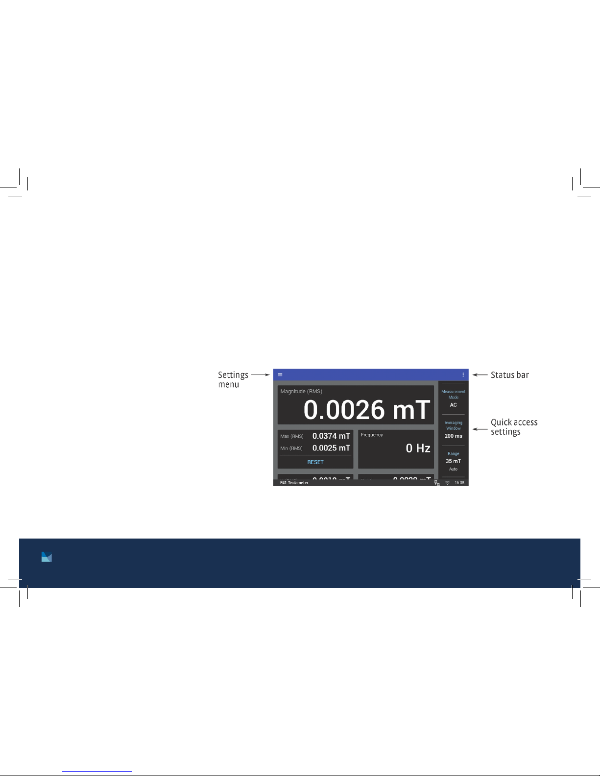
The Home screen displays readings such
as magnitude, max hold, relative, XYZ (F71),
and frequency. Touch a value to navigate to
a detail page containing more information.
The Magnitude detail screen for a single
axis probe measuring an AC field is shown
below.
From the quick access sidebar, you may change parameters such as:
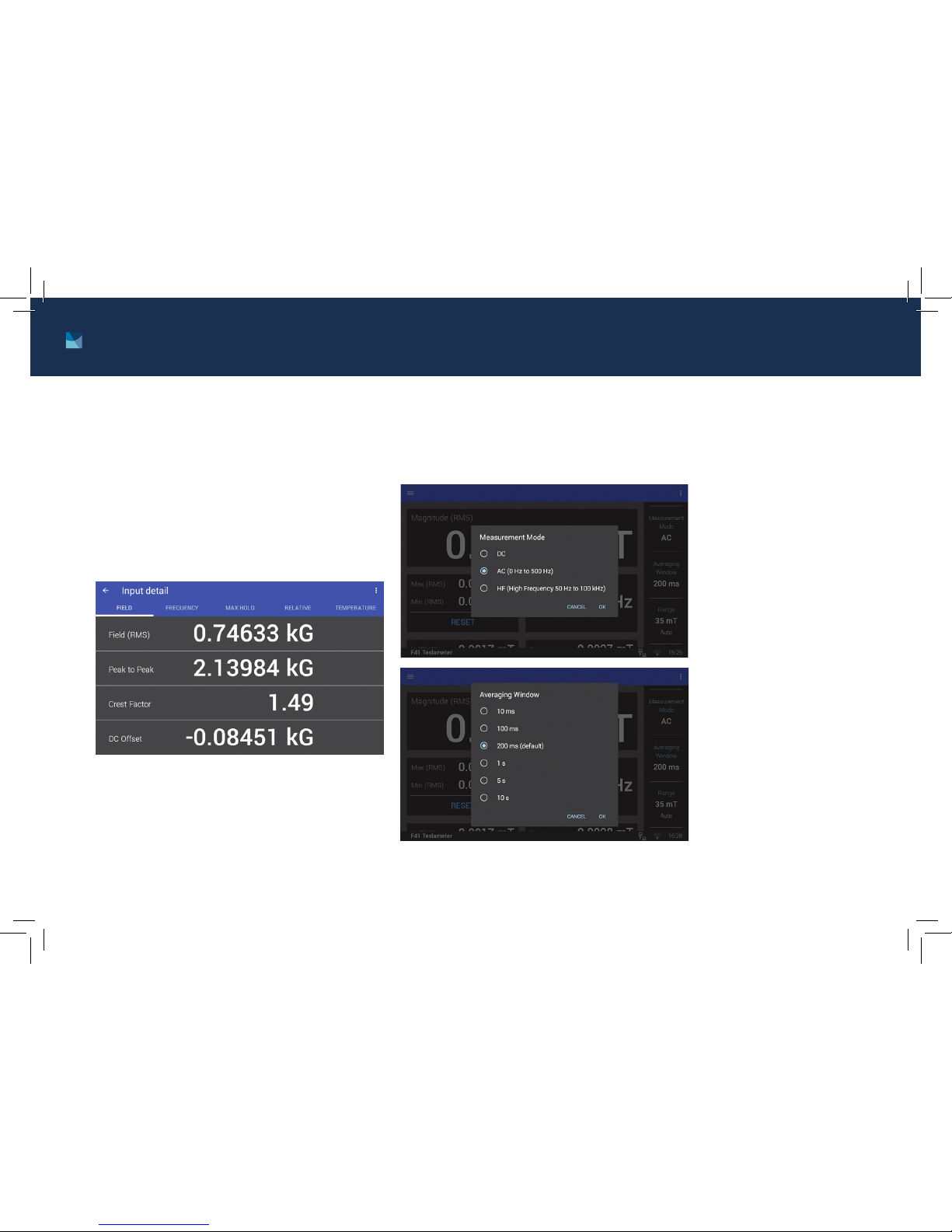
Measurement
Mode: On this
screen, choose the
mode you wish to
use, then click OK.
Averaging Window:
Select a time
interval setting,
then click OK. A
longer averaging
window will result
in more stable
readings, but will
respond more
slowly to field
changes.
Page 9
9 http://www.lakeshore.com/products/Gaussmeters/F71-F41-teslameters/
F71/F41 Teslameter Quick Start Guide
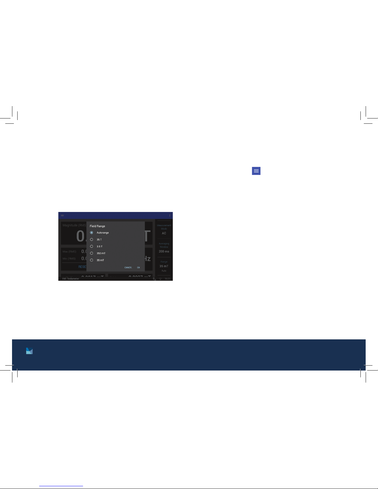
Range: Sets the maximum readable field and
display resolution. The F71/F41 teslameter is
equipped with an autoranging feature that will
automatically select the appropriate range for
the measured field. Select the range you wish to
use, then click OK.
NOTE: Autorange is the default setting.
Navigation drawer
Tap the Settings menu to go to the navigation
drawer to adjust settings.
Measurement setup: Includes settings for
Measurement mode, Averaging window, Range,
Units, and Temperature compensation.
Sensor Information: Provides general
information about the probe.
Analog output: Selects which channel’s analog
signal is routed to the output.
Digital I/O: Use this screen to configure the
functionality of the inputs and outputs.
System settings: Use this screen to adjust
settings, including Wi-Fi, display and sound,
firmware updates, and privacy
Page 10
10
F71/F41 Teslameter Quick Start Guide
Measurement modes
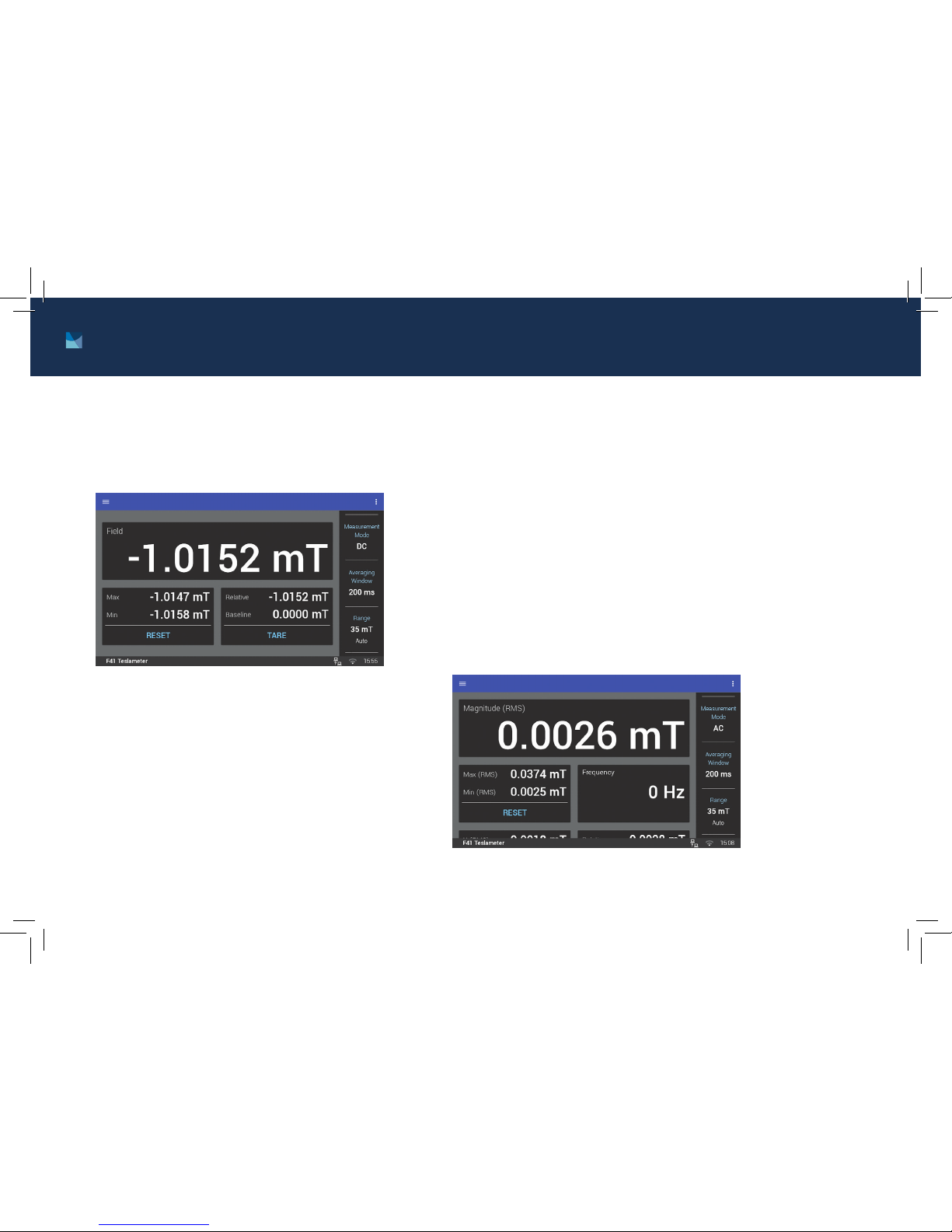
DC measurement mode
In DC measurement mode, the display
shows the measured DC field, the DC max
hold, the DC relative measurement.
AC measurement modes
In this mode, the display shows the RMS reading as well as the
frequency, RMS max hold, and the RMS relative measurement.
The F71/F41 teslameter offers two AC measurement bands to improve
overall AC measurement performance:
AC mode: has an operating range from DC to 500 Hz, but
should be limited to frequencies less than 60 Hz for rated
accuracies (reports both AC and DC components, and has
improved measurement performance)
High frequency mode: 50 Hz to 100 kHz (does not display DC
component, but can connect an oscilloscope to the analog
output to view higher frequency signals, allowing high speed
pulse capture)
Page 11
11 http://www.lakeshore.com/products/Gaussmeters/F71-F41-teslameters/
F71/F41 Teslameter Quick Start Guide
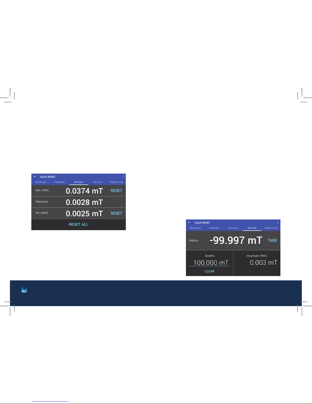
Max Hold
The maximum and minimum values are
displayed on the Home screen. Reset
these values by tapping the Reset button.
Tap the box to see a detail page where
the maximum and minimum can be reset
independently.
Relative Measurement
The relative measurement allows you to take field measurements
relative to a baseline field. The relative reading is equal to the present field value minus the baseline. The relative mode applies to the
DC reading in DC mode, and to the RMS reading in the AC and high
frequency modes.
Touch the Tare button to capture the present reading as a new baseline. Tap the box to see a detail page where the baseline can be set
manually.
TIP: This feature can be used to remove the small amount of
TruZero™ residual offset if a 0 reading is desired when the probe is
placed in a zero gauss chamber. Measure the residual offset with the
probe in a zero gauss chamber and set the relative baseline to the
average offset value.
Page 12
12
F71/F41 Teslameter Quick Start Guide
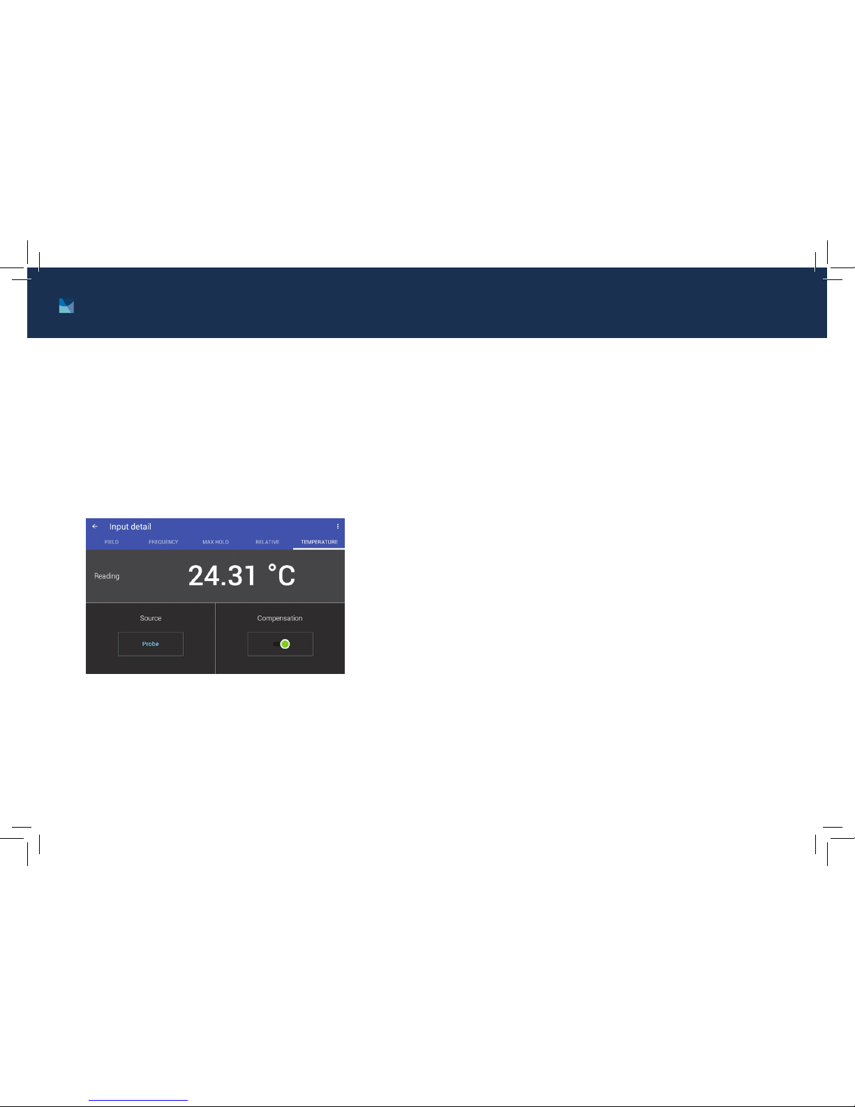
Temperature Measurement
The temperature compensation detail
screen displays the current temperature
reading for the probe tip temperature
sensor. Temperature compensation is on by
default but can be turned off for troubleshooting, or set to manual to allow temperature inputs that are outside the standard operating range of the probe
temperature sensor (0° to 90° C).
Screen Lock
The screen lock feature prevents accidental changes to parameter
values. When the screen is locked, some parameter values may be
viewed, but not changed, from the front panel.
To lock the screen:
1. Tap the Action icon (three dots in the top right corner of the
screen). A drop-down menu appears.
2. Tap Lock. A message indicating that the screen is locked appears
in the status bar.
To unlock the screen:
1. Tap the lock icon in the upper right corner of the screen.
2. Tap UNLOCK in the status bar. The screen unlocks.
Page 13
13 http://www.lakeshore.com/products/Gaussmeters/F71-F41-teslameters/
F71/F41 Teslameter Quick Start Guide
Probe accuracy considerations
The user must consider all the possible
contributors to the accuracy of the reading.
Both the probe and teslameter have
accuracy specifications that may impact
the actual reading.
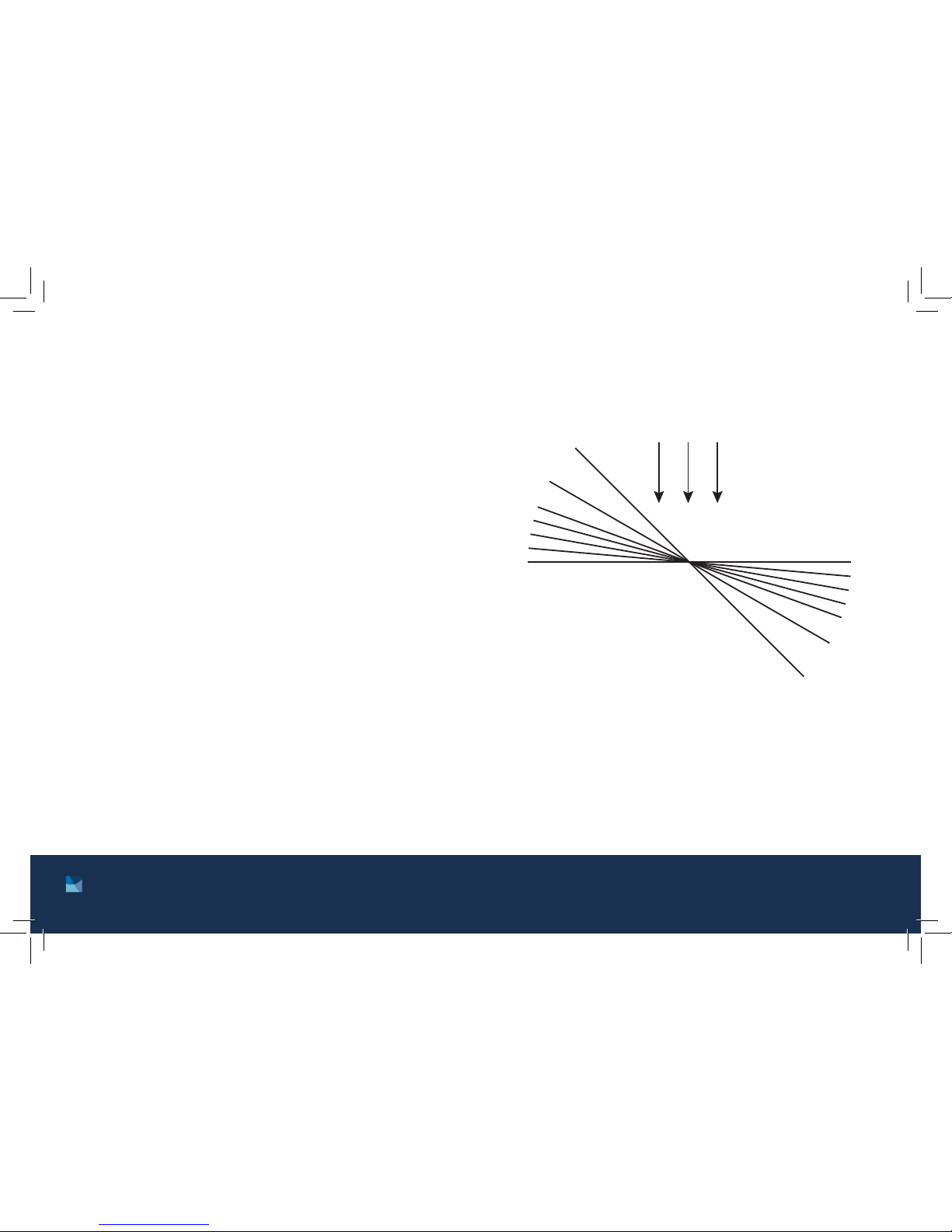
Probe readings are dependent on the angle
of the sensor (Hall sensor) in relation to the
magnetic field. Maximum output occurs
when the flux vector is perpendicular to the
plane of the sensor. This is the condition
that exists during factory calibration. The
greater the deviation from orthogonality
(from right angles in either of three axes),
the larger the error of the reading. For
example, a 5° variance on any one axis
causes a 0.4% error, a 10° misalignment
induces a 1.5% error, etc.
Effect of angular variations on
percentage of reading error where
percent error = (1 – cos α) 100
Deviation from
perpendicular (α)
Error
+B
0% 0°
0.4%
5°
1.5%
10°
3.4%
15°
20°
30°
6.0%
13.4%
29.3%
45°
Page 14
14
F71/F41 Teslameter Quick Start Guide
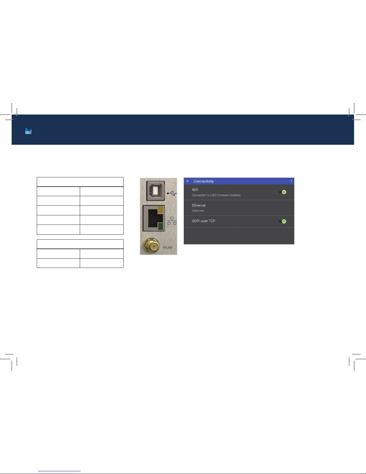
Computer interface connections
If desired, attach the teslameter to your PC using
Ethernet, USB, or Wi-Fi.
USB Serial port settings
Baud rate 115,200
Data bits 8
Parity None
Stop bits 1
Flow control RTS/CTS
Ethernet/Wi-Fi
IP address DHCP or Manual
Port 8888
Page 15
15 http://www.lakeshore.com/products/Gaussmeters/F71-F41-teslameters/
F71/F41 Teslameter Quick Start Guide
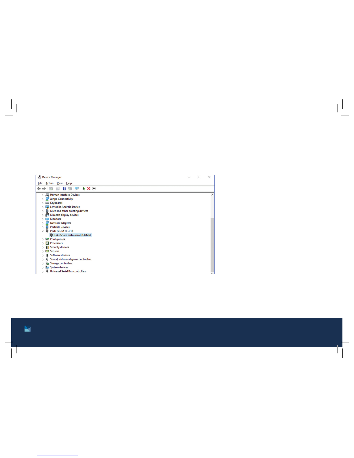
If you are unable to see the teslameter in this view, you may need to install the USB driver that can be found on the
Lake Shore Software web page: http://www.lakeshore.com/software/.
Use the SCPI command list (see the user’s manual) and your favorite serial terminal program (such as PuTTY or
Termite) to communicate with the teslameter via the remote interface. The USB connection will be listed as a virtual
COM port on your PC. If you are not able to connect, make sure you have the correct COM port selected. You can do
this by checking DeviceManager:
Page 16
16
F71/F41 Teslameter Quick Start Guide
Rev. 1.2 P/N 119-491 12 November 2018
Contacting Lake Shore
The Lake Shore Service Department is staffed Monday through Friday
between the hours of 8:00 a.m. and 5:00 p.m. EST, excluding holidays and
company shut down days: http://www.lakeshore.com/Service/
The Lake Shore Forum is also a great place to look for solutions, to post
issues, and to share successes:
http://forums.lakeshore.com/
For further documentation and information, please see
https://www.lakeshore.com/products/Gaussmeters/F71-F41-teslameters
Lake Shore Service
Lake Shore Cryotronics
Instrument Service Department
575 McCorkle Blvd.
Westerville, Ohio USA 43082-8888
Phone: 614-891-2244
Email: [email protected]
Web: www.lakeshore.com
 Loading...