

Lakeshore DRC-93C User Manual
USER’S MANUAL
Model
DRC-93C
Tem peratu re Controller
Obsolete
This manual describes an obsolete Lake Shore product. This manual is a copy from our archives
and may not exactly match your instrument. Lake Shore assumes no responsibility for this manual
matching your exact hardware revision or operational procedures. Lake Shore is not responsible
for any repairs made
to
the instrument based on information from this manual.
Notice:
Lakeshore.
Lake Shore Cryotronics, Inc.
575
McCorkle Blvd.
Westerville, Ohio 43082-8888 USA
E-Mail Addresses:
sales@lakeshore.com
service@Iakeshore.com
Visit Our Website:
www.
lakeshore.com
Fax: (614) 891-1392
Telephone: (614) 891-2243
Methods and apparatus disclosed and described herein have been developed solely on company funds of Lake Shore Cryotronics, Inc.
No
government
rights of Lake Shore Cryotronics, Inc. in these developments. Methods and apparatus disclosed herein may be subject to
existing or applied for. Lake Shore Cryotronics,
modifications, or products at any time without notice. Lake Shore shall not be liable
consequential damages in connection with furnishing, performance, or use of this material.
Obsolete
or
other contractual support
Manual
or
relationship whatsoever has existed which in any way affects or mitigates proprietary
Inc. reserves the right to add, improve, modify, or withdraw functions, design
for
errors
contained herein or for incidental or
U.S.
March
Patents
1988
SERIAL
MB
DB
I
N
S
T
R U C
MODEL DRC-93C
TEMPERATURE CONTROLLER
T
I
O
N
M
A N U A
NUMBER
SOFTWARE
SOFTWARE
L
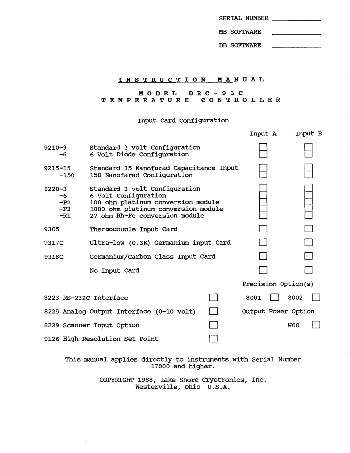
Input Card Configuration
9210-3
-6 6
9215-15
-150 150
9220-3
-6
-P2
-P3
-R1
93
05
9317C
9318C
8223 RS-232C
Standard 3 volt Configuration
Volt Diode Configuration
Standard
15
Nanofarad Capacitance Input
Nanofarad Configuration
Standard 3 volt Configuration
6
Volt Configuration
100
ohm
platinum conversion module
1000
27
ohm
platinum conversion module
ohm
Rh-Fe conversion module
Thermocouple Input Card
Ultra-low
(0.3K)
Germanium input Card
Germanium/Carbon Glass Input Card
No Input Card
Interface
Input
A
Input
Precision Option
8001 8002
B
(s)
8225
8229
9126
Analog Output Interface
Scanner Input Option
(0-10
volt) Output Power Option
W6
High Resolution Set Point
This manual applies directly to instruments with Serial Number
COPYRIGHT
17000
1988,
and higher.
Lake Shore Cryotronics, Inc.
Westerville, Ohio U.S.A.
0
WARRANTY
Lake Shore Cryotronics, Inc., the manufacturer, warrants this product to
the owner for a period of
12
months from the date of shipment.
During the
warranty period, under authorized return of instruments or component
parts to Lake Shore freight prepaid, the company will repair, or at its
be
option replace, any part found to
defective in material or
workmanship, without charge to the Owner for parts, service labor or
associated customary shipping cost.
Replacement or repaired parts will
be warranted for only the unexpired portion of the original warranty.
All products are thoroughly tested and calibrated to published
specifications prior to shipment. Calibration Certifications are offered
for six month periods only.
re-certification service is offered by Lake Shore Cryotronics,
Where such documentation must be updated, a
Inc. at a
reasonable cost.
LIMITATION
OF
WARRANTY
This warranty does not apply to defects resulting from improper or
inadequate maintenance, unauthorized modification or misuse, operation
outside of the environmental specifications for any product or part or
buyer-supplied software or interfacing.
THIS WARRANTY IS
INCLUDING MERCHANTABILITY OR FITNESS FOR A PARTICULAR PURPOSE, WHICH
EXPRESSLY EXCLUDED.
TO
RESPECT
THIS PRODUCT
INCIDENTAL OR CONSEQUENTIAL DAMAGES
IN
LIEU OF
ANY
THE
OWNER AGREES
SHALL
OTHER WARRANTIES, EXPRESSED OR IMPLIED,
THAT
BE
SET
ARE
EXPRESSLY EXCLUDED.
CERTIFICATION
LAKE
FORTH
SHORE'S LIABILITY WITH
IN THIS WARRANTY,
ARE
AND
Lake Shore Cryotronics, Inc. certifies that this product has been
inspected and tested in accordance with its published specifications and
that this product met its published specifications at the time of
shipment.
The accuracy and calibration of this product at the time of shipment are
traceable to the United States National Bureau of Standards.
COPYRIGHT
3/88
LSCI
TABLE
Model DRC-93C Temperature Controller
OF
CONTENTS
SECTION
1.1
1.2
1.3
1.4
2.1
2.2
2.3
2.4
2.5
2.6
2.7
2.8
INTRODUCTION
DESCRIPTION.
SPECIFICATIONS
OPTIONS..
SECTION
INTRODUCTION
INITIAL INSPECTION
PREPARATION FOR USE
2.3.1
2.3.2
2.3.3
2.3.4
2.3.5
2.3.6
2.3.7 J3
2.3.8
2.3.9
REMOTE SENSOR ID Connector
IEEE-488 INTERFACE Connector
OPTIONS..
ENVIRONMENTAL REQUIREMENTS
2.7.1
2.7.2
REPACKAGING FOR SHIPMENT
I
-
GENERAL INFORMATION
........................
........................
.......................
.........................
II
-
INSTALLATION
........................
.....................
.....................
Power Requirements
Power Cord.
Grounding Requirements
Bench Use
Rack Mounting
Sensor Input Connections
Sensor Output Monitors
SENSOR ID Switches
Heater Power
2.3.9.1
2.3.9.2
.........................
Operating Temperature
Humidity/Altitude
.....................
......................
....................
.....................
MAX
HEATER POWER Limit
Current or Power Output Display
..................
................
...............
..............
..................
...........
.......
.................
................
.................
................
..................
..................
1-1
1-1
1-3
1-3
2-1
2-1
2-1
2-1
2-1
2-1
2-2
2-2
2-2
2-3
2-3
2-4
2-4
2-4
2-4
2-5
2-5
2-5
2-5
2 -5
2-5
SECTION
3.1
3.2
3.3
3.4
COPYRIGHT
INTRODUCTION
INSTRUMENT CONFIGURATION
3.2.1
3.2.2
3.2.3
3.2.4
CURVE ENTRY..
PRECISION OPTIONS
3.4.1
3.4.2
3.4.3
III - OPERATING INSTRUCTIONS
.........................
...................
Input Card Configurations
Single Input Card
Dual Input Cards
Old Version Input Cards
...................
....................
........................
.......................
The Model
The Model
The Model
3/88
LSCI
8000
8001
8002-05
Precision Option
Precision Option
Precision option
...............
................
............
............
...........
3-1
3-1
3-1
3-1
3-1
3-1
3-1
3-2
3-2
3-2
3-2
i
TABLE OF CONTENTS. CONT'D
3.5
3.6
3.7
3.8
CONTROL FUNDAMENTALS
CONTROLS AND INDICATORS
FRONT
POWER ON
3.7.1
3.7.2
3.7.3
3.7.2
TEMPERATURE BLOCK
3.8.1
3.8.2
3.8.3 8229
3.8.4
3.8.5
3.8.6
3.8.7
3.8.8
3.8.9
...........................
Power Up Sequence
Power-up Status
Blue Legend Keys
Black Legend Keys
Sample and Control Sensor Inputs
Upper and Lower SENSOR Number
Scanner Input Option
SCAN
The SCAN Dwell Time
Upper and Lower Display Units
3.8.6.1
3.8.6.2
Display Resolution
3.8.7.1
Filtering the A and B Inputs
Math Functions
Function
Units Select
Sensor Units Mode
3.8.6.2.1Voltage
3.8.6.2.2
3.8.6.2.3
Temperature Display Resolution Set
.....................
.......................
.....................
.....................
....................
PANEL DESCRIPTION
...................
....................
....................
...................
............
.............
...............
..................
.............
.................
...............
Units
Resistance Units
Capacitance Units
............
..........
..........
...................
......
..............
3-2
3-2
3-2
3-2
3-3
3-3
3-5
3-5
3-5
3-5
3-6
3-6
3-6
3-6
3-6
3-7
3-7
3-7
3-7
3-7
3-8
3-9
3-9
3.9
ii COPYRIGHT
SENSOR
3.9.1
3.9.2
3.9.3
CURVE
Standard and Precision Option Curves
3.9.1.1
3.9.1.2
3.9.1.3
3.9.1.4
External Scanners Models
3.9.2.1
3.9.2.2
3.9.2.3
Programming Curves from the Front Panel
3.9.3.1
3.9.3.2
3.9.3.3
3.9.3.4
SELECTION
....................
..........
The Precision Option
Display of Accessed Curve Number
Addition
Changing the Curve used by a Sensor
Selection of the
The Correlation Table
Modifying the Correlation Table from
the Front Panel
Accessing Stored Curve Data
Entering New Curves
Editing Existing Curve Data
Summary of Curve Programming from the
Front Panel
of
8229
Scanner Option
8085
REMOTE
................
..................
.............
.............
POSITION DATA
.............
..........
..............
..........
.......
........
......
.....
........
3/88
3-10
3-10
3-10
3-10
3-11
3-11
3-11
3-11
3-12
3-12
3-13
3-13
3-14
3-15
3-15
LSCI

TABLE OF CONTENTS, CONT'D
3.10
3.11 HEATER POWER
3.12 LOCAL/REMOTE
3.13 REMOTE SENSOR ID
3.14 HEATER
4-1. IEEE-488 INTERFACE
SET
POINT
3.10.1 SETPOINT
3.11.2 GAIN
3.11.3 RATE.
3.11.4 RESET
3.11.5
AND
..........................
MANUAL
CONTROL
BLOCK
........................
.........................
.........................
HEATER POWER
.........................
%
3.11.1 HEATER
3.11.2 The HEATER
3.12.1
3.12.2 REMOTE
SECTION IV - REMOTE OPERATION
LOCAL
CURRENT
........................
POWER
BLOCK
RANGE
......................
.........................
.........................
REAR
LIMIT
PANEL DESCRIPTION
.......................
.....................
.....................
..................
..................
.................
3-16
3-16
3-16
3-16
3-17
3-17
3-17
3-17
3-17
3-19
3-19
3-19
3-19
3-19
4-1
4.2 GENERAL IEEE SPECIFICATIONS
4.3 INTERFACE CAPABILITIES
4.4 DRC-93C IEEE-488 ADDRESS SWITCH
4.4.1 Terminating Characters (delimiters) 4-3
4.4.2 Talker and/or Listener Configuration 4-3
4.4.3 The IEEE-488 INTERFACE bus address 4-5
4.5 IEEE-488
4.5.1 The Uniline Commands
4.5.2 The Universal Commands
4.5.3 The Addressed Commands
4.5.4 The Unaddress Commands
4.5.5 Device-Dependent Commands
4.5.6 Talker and Listener Status
4.6 PROGRAMMING INSTRUCTIONS
4.6.1 Commands and Requests
4.7 INSTRUMENT SETUP
4.7.1
4.7.2
BUS
COMMANDS
COMMANDS
EOI Status
Interface Mode - The MN1 Command
4.7.2.1 Local
....................
-
The ZN1 Command
....................
AND
...................
................
..................
................
AND
REQUESTS 4-7
OPERATION 4-1
...............
..........
4-2
4-3
.........
.........
..........
4-5
4-5
...............
...............
...............
..............
..............
4-5
4-5
4-6
4-6
4-6
4-7
4-7
...........
.............
...........
4
-7
4 -7
4-7
COPYRIGHT 3/88 LSCI
iii
TABLE OF CONTENTS, CONT'D
4.7.2.2 Remote 4-7
4.7.2.3 Local Lockout 4-9
4.7.3 Terminating Characters - The
4.7.4 Clear
4.7.5 The “W2” Data String
4.7.6 The
4.8 SECTION OF QUANTITIES FOR
-
UNITS.
4.8.1
4.8.2 Units for Sample Display
4.8.3 Control Sensor Selection
4.8.4 Sample Sensor Selection
4.8.5 Resolution for The Control and Sample
4.8.6 Selection of Deviation for Control and Sample
4.8.7 Selection
4.8.8 4-12
4.8.9 The A and B ID Information
4.8.10 The
SENSORS.
Units for Control Display and Set Point
The F4CON, F4COFF, F4SON and F4SOFF Commands
The F50N, F5OFF and F5CLR Commands
Sensor Curve # Selection - The NC1N1N2N3 Command
........................
“WI”
“WD”
Data String
The FOC1 Command
The F3CN1 and F3SN1 Commands
of
The AC1C2 and BC1C2 Commands
Data String
....................
RESOLUTIONS
MATH
Functions
................
TN,
Command
.......
.................
.................
THE
CONTROL
AND
DEVIATION (Table 4-7)
AND
SAMPLE
-
DISPLAYS
...
..............
-
The FlC1 Command
-
The F2CC1N1 Command
-
The F2SC1N1 Command
.....
....
....
-
........
-
.....
ON.
OFF and CLEAR
-
..........
...
-
........
.................
4-9
4-9
4-11
4-11
4-11
4-11
4-11
4-11
4-11
4-11
4-12
4-12
4-12
4-12
4.9
4.10
4.11
THE
CONTROL COMMANDS
4.9.1 The Set Point Value
4.9.2 The
4.9.3 Setting the GAIN (Proportional) - The P Command
4.9.4 Setting the RESET (Integral) - The I Command
4.9.5 Setting the
4.9.6 Heater Range
4.9.7
4.9.8 The “W3” Data String
THE
SCANNER
4.10.1
4.10.2 Setting the Dwell Time
4.10.3 Enabling the Scan Function
4.10.4 Holding the Scan Function
4.10.5 The
THE
SERVICE REQUEST. STATUS REGISTER. STATUS REPORTS
AND
THE
4.11.1 The Service Request
4.11.2 The Status Register and Status Reports
“WP”
%
Manual Heater Power - The H Command
SCAN
The YAN1N2N3 and YBON2N3 Commands
WY"
STATUS REGISTER
4.11.2.1 Status Reports
4.11.2.2 Status Report 2
Request Data String
INPUT
Programming Instructions
Data String
Display and Control Data Ready
....................
-
The S Command
.........
.............
RATE
(Derivative) - The D Command
-
The R Command
.............
.................
CARD
...................
.............
-
..........
-
The
YS
Command
-
The
YH
Command
.................
MASK
................
.................
0
and
1
-
-
The Control Channel Limit
.....
........
.....
......
........
.......
...
....
.
4-12
4-12
4-16
4-16
4-16
4-16
4-16
4-16
4-16
4-16
4-16
4-16
4-17
4-18
4-18
4-18
4-19
4-19
4-19
4-19
iv
COPYRIGHT 3/88 LSCI
TABLE
4.11.2.3 Status Report 3-Display Sensor Channel Change 4-19
4.11.2.4 Status Report 5
4.11.2.5 When operating without the Service Request
4.11.3 The Status Register Mask - The QC1C2 Command
4.11.3.1 Status Register Mask Bits 0 and 1
Display and Control Data Ready Enables
4.11.3.2 Status Register Mask Bit 2
The Control Channel Limit Enable
4.11.3.3 Status Register Mask Bit
Display Sensor Channel Change Enable
4.11.3.4 Status Register Mask Bit
Overload/Error Indicator Enable
4.11.3.5 Examples for setting Mask
4.11.3.6 Status Register Mask at Power Up
4.11.3.7 The “WQ” Data String
OF
CONTENTS. CONT'D
-
Overload/Error Indicator
-
-
......
3
-
5
-
.......
..........
......
............
.
.
.....
...
....
4-20
4-20
4-20
4-21
4-21
4-21
4-21
4-21
4-23
4-23
4.12 SAVING AND RESTORING EXECUTABLE (INTERNAL)
4.12.1 Requesting a Program Step for Saving - WEN1N2 Command
4.12.2 Transmitting a Program Step to the 93C
The EN N2
4.12.3 Examples
4.12.3.1 Program to Request and Store Program
4.12.3.2 Program to Restore Program Step
4.12.3.3 National Instruments GWBASIC and BASICA IBM
4.12.3.4 National Instruments GWBASIC and
4.12.3.5 National Instruments QUICK BASIC IBM
4.12.3.6 National Instruments QUICK BASIC IBM
4.13 COMMAND OPERATIONS
4.14
OUTPUT
4.14.1 The “WS”
4.14.2 The “WO” Data String
DATA STATEMENTS
of
Executable (Internal) Program Steps
Step
10 using the HP86B
Example
Example
Example
Example
,
“WC” and
Saving and Restoring
......................
C1
#
-C60 Command
1
thru
10 using the HP86B
...........
.............
of
WEN1N2 Request
of
E Command
of
WEN1N2 Request
of
E Command
.............
.............
...................
“WP”
Data Strings
.................
PROGRAMS
.....
-
.....
......
#
1 thru
..........
BASICA
..........
.........
IBM
4-23
4-23
4-23
4-24
4-24
4-25
4-25
4-26
4-26
4-27
4-28
4-28
4-28
4-28
4.15 SAMPLE PROGRAMMING
4.15.1HP86B Keyboard Interactive Program
4.15.2 National Instruments GWBASICA or BASICA IBM Example
4.15.3 National Instruments QUICK BASIC IBM Example
Bus
4.15.4 HP86B
4.16 SENSOR
4.16.1
4.16.2 The XDN1N2 Command
COPYRIGHT 3/88 LSCI
CURVE
The
XDT Comand
Commands Program
PROGRAMMING INSTRUCTIONS
.....................
..........
.....
..............
............
...................
..................
.
4-30
4-30
4-30
4-31
4-31
4-32
4-32
4-33
V
TABLE
OF
CONTENTS, CONT'D
4.16.3
4.16.4
4.16.5
4.16.6
4.16.7
SECTION
5.1
5.2
5.3
5.4
5.5
5.6
INTRODUCTION
GENERAL
FUSE REPLACEMENT
LINE VOLTAGE SELECTION
PERFORMANCE VERIFICATION
5.5.1
5.5.2
CALIBRATION.
5.6.1
5.6.2
5.6.3
5.6.4
The XDA Command
The
XCN1N2
The
XEN1N2
The
XKN1N2*
The
XAC1C2=N1N2*
V
-
MAINTENANCE
Command
Command
Command
...................
..................
..................
.................
and
XBC1C2=N1N2*
........................
MAINTENANCE..
...................
......................
...................
..................
Performance Verification Connector
Performance Verification Procedure
.........................
Input Card Calibration
Set Point Voltage Calibration
Calibration
Calibration
of
GAIN, RATE and RESET
of
Power Output
................
Commands
......
..........
..........
............
.........
.............
4-36
4-36
4-37
4-37
4-37
5-1
5-1
5-1
5-1
5-2
5-2
5-2
5-2
5-2
5-2
5-3
5-3
5.7
SECTION
6.1
6.2
6.3
6.4
6.5
vi COPYRIGHT
TROUBLESHOOTING.
VI
-
PROGRAMMING
INSTRODUCTION
PROGRAM STEPS
PROGRAM
SUMMARY
INTERNAL
6.5.1
6.5.2
6.5.3
6.5.4
6.5.5
6.5.6
6.5.7
6.5.8
STEP FORMAT
OF
PROGRAM
Starting the Program Edit Mode
Program Step Selection
Entering the Program Command and
REPEAT COUNT or
Entering the Setpoint, Gain, Rate and Reset
Entering Other Parameters
Entering the Timer Value
Entering
Ending or Aborting the Programming Mode
........................
AND
COMMANDS
.......................
INSTRUCTIONS
SIZE
...................
.....................
.....................
ENTRY
...................
............
................
RAMP
COUNT
JUMP
..............
VECTOR,
..............
...............
the
Program
Step
into
Memory
........
.......
.....
3/88
5-4
6-1
6-1
6-1
6-1
6-3
6-3
6-3
6-4
6-4
6-4
6-4
6-4
6-4
LSCI
TABLE
OF
CONTENTS, CONT'D
6.6
6.7 CLEARING
6.8
SECTION
APPENDIX
APPENDIX
APPENDIX
RUNNING
EXAMPLES
6.8.1 Example
6.8.2 Example #2 - Ramp and
6.8.3 Example
6.8.4
Example #4 - Repeat
VII
-
A
-
B
-
C
-
THE
PROGRAM.
ALL
INTERNAL PROGRAM MEMORY
....................
............
..........................
#1
-
#3
ACCESSORIES,
Standard
Sensor
Error
Curve
Curve
Code
Ramp and
-
Repeated Setpoint Ramp Up, Soak,
and Ramp
Limit
INPUT
Data
Information
Summary
of
of
CARDS
Soak
Soak
Down
10
..............
..............
with Gain Ramping
Example
Cycles
AND
#3
with a
...........
OPTIONS
.....
6-4
6-5
6-5
6-5
6-6
6-7
6-8
COPYRIGHT
3/88
LSCI vii
LIST
OF
TABLES AND ILLUSTRATIONS
SECTION
Table
SECTION
Table
Figure 2-1.
Table 2-2.
Figure 2-2.
Table 2-3. J3 MONITORS Connections.
Table 2-4.
SECTION
Figure
Table
Table
Table
Table 3-4. Correlation Table for Curve
Figure
Table 3-6. Pin Assignments for the J5 REMOTE SENSOR ID Connector
1-1.
2-1.
3-1.
3-1.
3-2.
3-3.
3-2.
I
-
GENERAL INFORMATION
Specifications, Model DRC-91C Temperature Controller
II
-
INSTALLATION
Line Voltage Selection
Typical Rack Configuration
INPUT Connections for J1 INPUT A and J2 INPUT
Sensor Connections
................
..............
B
..................
...............
REMOTE SENSOR ID Connector Assignments
III
-
OPERATING INSTRUCTIONS
DRC-93C Temperature Controller - Front Panel
System Resolution Versus Sensor Sensitivity
Standard Curve Information
Sensor Curve Table Information
Precision Option Table
from REMOTE POSITION DATA
DRC-93C Temperature Controller - Rear Panel
..............
-
................
#
..............
........
.....
.....
.....
...
.
.
3-10
3-10
3-13
3-18
3-19
1-4
2-1
2-2
2-2
2-2
2-3
2-4
3-4
3-8
SECTION IV - REMOTE OPERATION
Table 4-1. Interface Functions.
Figure 4-1. IEEE-488 Address Switch for the DRC-93C
Table 4-2. Allowable Address Codes for the DRC-93C
Table 4-3. IEEE-488
Table 4-4. DRC-93C Command Summary of Instrument Setup
Table 4-5. DRC-93C Summary of Output Requests
Table 4-6. DRC-93C Interface Setup Commands and Request Status
Table 4-7. DRC-93C Command Summary for Instrument Setup
Table 4-7. DRC-93C Request Summary for Instrument Setup
Table 4-8. C1 and C2 in A ID and
Table 4-9. DRC-93C Command Summary for Setpoint Setup
Table 4-10 DRC-93C Command/Request Summary for Control Setup
Table 4-11 DRC-93C Command/Request Summary for Scanner Setup
Figure 4-2. 93C Status Register
Table 4-12 Commands to Fix the Status Register Mask
Table 4-13 93C Command/Request Summary for Status Register Mask
Table 4-14 DRC-93C Command/Request Summary for Program Step
Table
viii COPYRIGHT
4-15
DRC-93C Output Data Requests
Bus
Commands
.................
.......
.......
................
.....
..........
.....
.....
B
ID, the SENSOR ID's.
.....
......
MASK
and Status Register Format
.......
...
.............
. .
.
.
.
.
.
3/88
4-2
4-3
4-4
4-6
4-8
4-9
4-10
4-13
4-14
4-14
4-15
4-17
4-18
4-22
4-22
4-23
4-24
4-29
LSCI
TABLES OF TABLES
AND
ILLUSTRATIONS,
CONT'D
Table
Table
Table
Table
SECTION VI - PROGRAMMING INSTRUCTIONS
Table
Table
4-16
4-17
4-18
4-19
6-1.
6-2.
Sensor
Sensor
XDN1N2
Conversion
Programmer
PROGRAMMING COMMANDS..
Curve
Curve
Sensor
of
Summary.
Commands
Information
Curve
Raw
output
Units
.................
and
Description
Table
Format
Data
...............
Output
for
the
........
Format
..........
XC Command
.....
...
4-34
4-35
4-35
4-38
6-1
6-2
COPYRIGHT
3/88
LSCI
ix
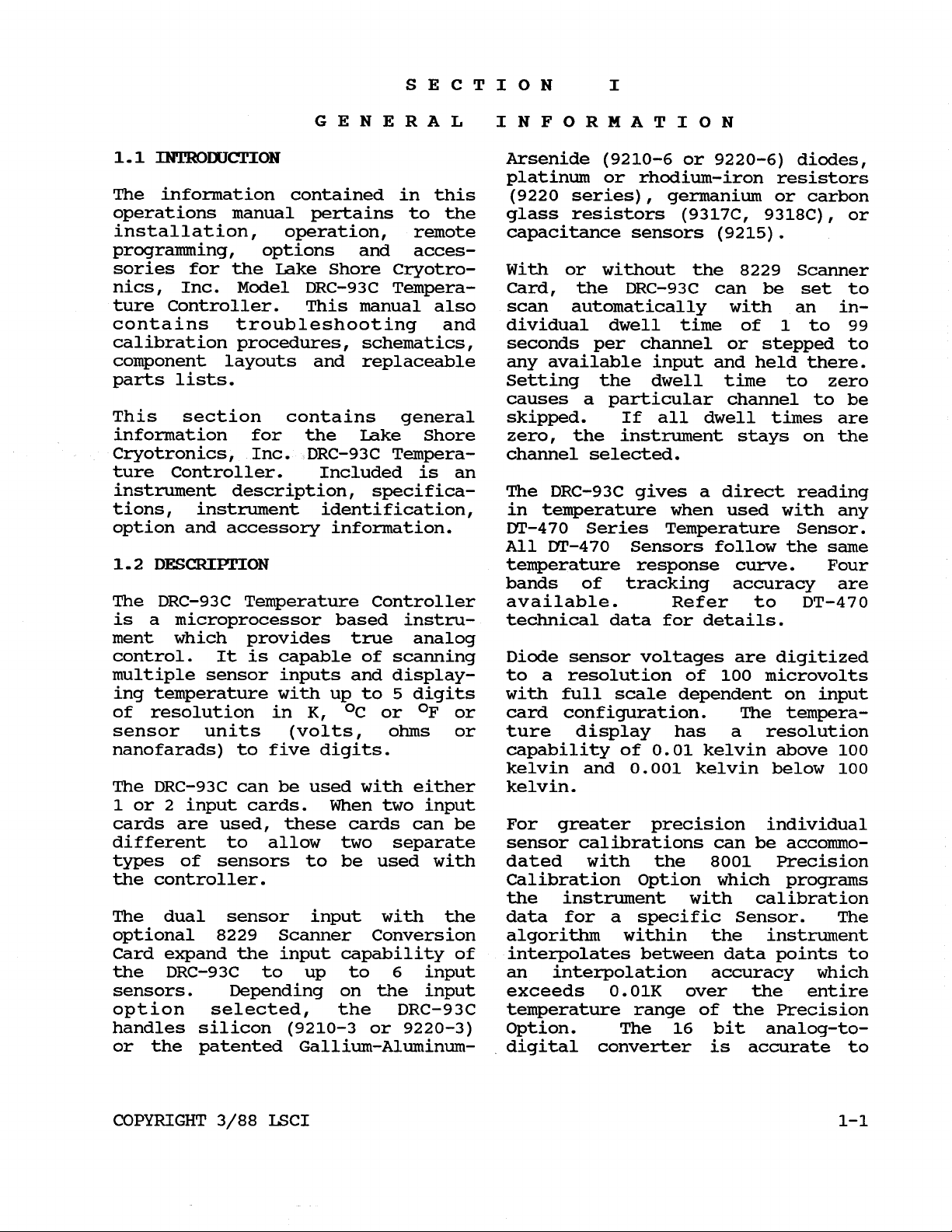
1.1
INTRODUCTION
SECTION
GENERAL INFORMATION
Arsenide
I
(9210-6
or 9220-6) diodes,
platinum or rhodium-iron resistors
The information contained in this
(9220
series), germanium or carbon
operations manual pertains to the glass resistors (9317C, 9318C), or
installation, operation, remote capacitance sensors (9215).
programming, options and acces-
sories for the Lake Shore Cryotro- With or without the 8229 Scanner
nics, Inc. Model DRC-93C Tempera- Card, the DRC-93C can be set to
ture Controller. This manual also scan automatically with an incontains troubleshooting and dividual dwell time of
calibration procedures, schematics, seconds per channel
or
1
to
99
stepped to
component layouts and replaceable any available input and held there.
parts lists. Setting the dwell time to zero
causes a particular channel to be
This section contains general skipped. If all dwell times are
information for the Lake Shore zero, the instrument stays on the
Cryotronics, Inc. DRC-93C Tempera- channel selected.
ture Controller. Included is an
instrument description, specifica- The DRC-93C gives a direct reading
tions, instrument identification, in temperature when used with any
option and accessory information. DT-470 Series Temperature Sensor.
All DT-470 Sensors follow the same
1.2
DESCRIPTION
temperature response curve. Four
bands of tracking accuracy are
The DRC-93C Temperature Controller available. Refer to DT-470
is a microprocessor based instru- technical data for details.
ment which provides true analog
control. It is capable of scanning Diode sensor voltages are digitized
multiple sensor inputs and display- to a resolution
ing temperature with up to
of resolution in K, OC or
sensor units (volts,
5
digits with full scale dependent on input
OF
or card configuration. The tempera-
ohms
or
ture display has a resolution
nanofarads) to five digits. capability of
kelvin and
0.001
of
100
0.01
kelvin above
kelvin below
microvolts
100
100
The DRC-93C can be used with either kelvin.
1
or 2 input cards. When two input
cards are used, these cards can be For greater precision individual
different to allow two separate sensor calibrations can be accommotypes of sensors to be used with dated with the
8001
Precision
the controller. Calibration Option which programs
the instrument with calibration
The dual sensor input with the data for a specific Sensor. The
optional
8229
Scanner Conversion algorithm within the instrument
Card expand the input capability of interpolates between data points to
the DRC-93C to up to
6
input an interpolation accuracy which
sensors. Depending on the input exceeds 0.01K over the entire
option selected, the DRC-93C temperature range of the Precision
handles silicon
(9210-3
or
9220-3)
option. The
16
bit analog-to-
or the patented Gallium-Aluminum- digital converter is accurate to
COPYRIGHT
3/88
LSCI 1-1
Section
1
Model
DRC-93C
plus or minus the least significant tion accuracy, the software
bit, which for the
470
series interpolation accuracy and the
sensor results in an uncertainty of calculation of the resistance
lmK
below 28K and
with a transitional region between the order of
45mK
above
40K
results in an overall accuracy on
10mK.
these two temperatures. Therefore,
at temperatures below
overall system accuracy, the
the instrument accuracy (1lmK) and can
28K,
sum
the These input option cards are easily
of installed by the user; thus, units
be
changed or upgraded to
that of the calibration itself satisfy changing requirements.
(Lake Shore calibrations are
typically better than 20mK within The ample memory space provided in
this region) is
system accuracy gradually moderates curves to
to a typical value of
40K.
See the Lake Shore
&
30mK. Above
+75mK
28K,
the DRC-93C allows several response
be
stored in the instru-
above ment. Depending on the complexity
IDW
of the curves, up to 25 can be
Temperature Calibration Service programmed into the unit. The
brochure for additional discussion active curve is selected either
of calibration accuracy. from the front panel or over the
remote interface.
The Model DRC-93C can also be used
with the
9220
input card which The data for calibrated sensors can
handles both diodes and positive be stored in the instrument as an
temperature coefficient metallic
8001
Precision Option or by the
resistors., i.e., platinum or customer via the front panel or
rhodium-iron resistors. The DIN remote interfaces. These curves
curve is standard within the can contain up to
99
sensor
instrument and is called up temperature data points. With the
automatically unless a positive standard precision option format of
temperature coefficient precision
31
data points and an
18
character
option curve is selected for that information line, up to twenty
input. The accuracy of the reading curves can be stored.
is dictated by the sensor and its
conformity to the DIN curve. The Although data points are stored as
tolerance on these devices
is
given a table, the interpolation
on the technical data sheet for the algorithm used results in the
Lake Shore
PLATINUM
RTD's. The equivalent of a high order
combined accuracy of the instrument Chebychev polynomial calculation in
and a calibrated resistor with a the converting of the input
precision option is on the order of voltage (or resistance) to tempera-
40mK
sensor (above
inum)
option
over the useful range of the ture. This is done by means of a
.
40K
Note that a precision Lake Shore Cryotronics.
is
required for a rhodium-
for the plat- proprietary algorithm developed at
iron to read correctly in tempera- An averaging algorithm can be
ture
.
selected to average up to ten
temperature readings. This mode
The Model DRC-93C with the 9318C eliminates noise within the system
germanium/carbon-glass input card analogous to averaging with a
results in the most accurate system digital voltmeter. This averaging
below
50K
in temperature.
For both
mode can be disabled from the front
sensors, a precision option is panel or over the remote interface
required to read in temperature. for a given input if the customer
Near
4K,
the overall accuracy of prefers not to average readings.
the system, including the calibra-
1-2
COPYRIGHT
3/88
LSCI
Model
DRC-93C
Section
I
The control set point is also changing the setting.
displayed on the front panel and
can be set from the front panel. The maximum power can also be
The set point automatically takes limited by using the rheostat on
on the units selected for the the rear panel. Power can be
control sensor. In the units mode reduced on the
the set point can
digits with the range of defined by
be
set to five value between
of a factor of ten in power.
MAX
MAX
scale to any
and a reduction
the control sensor input card. The
standard set point temperature can When greater output power is
be set to
temperature is converted to an stage can provide
equivalent voltage with a resolution of
100
0.1
degree. This required, the optional W60 output
microvolts out of
3
25
ohm
load.
60
watts into a
volts full scale. The optional An IEEE-488 interface is standard
High Resolution Set point expands in the DRC-93C. This interface can
the set point resolution to
degrees
100.
expanded to
100
and
0.001
degrees below front-panel functions. When two
The equivalent voltage is input cards are used, data from
25
microvolts out of
0.01
be
3
both inputs
used to remotely control all
is
available via the
volts full scale. This results in interface.
a settability of approximately
kelvin above
40K
and
0.001
0.01
kelvin
1.3
SPECIFICATIONS
below 28K for the DT-470 series
sensors. Instrument specifications are
listed in Table
1.1.
These
The control section of the DRC-93C specifications are the performance
provides three-term temperature standards or limits against which
control. Proportional
integral
(RATE)
range from
990
to 1 range. The options for the DRC-93C
(RESET)
and derivative
are individually set with a
0.1
to
99
resulting in a
(GAIN),
the instrument is tested.
1.4
OPTIONS
Controller are listed in Section
Heater power output
of
the DRC-93C
VII.
Temperature Controller is a maximum
of
50
used.
watts when a
A
digital bar graph on the into the DRC-93C. The options are
50
ohm
heater is Three option ports are designed
front panel displays the output as field installable by the user.
a percentage of output range
selected. Thus, the user can con- 822x-series options can be factory
veniently monitor power applied to installed in the DRC-93C or fieldhis system.
which require lower heater power,
To
accommodate systems installed at a later the. The
8223
RS-232C Interface Option
the maximum output can be at- operates similar to the IEEE-488
tenuated in four steps of a decade interface. With the display in
each. Three resistance ranges are temperature units, the Model 8225
available; 0-25, 25-35 and
Ohms.
35-50
Analog Output option is available
to provide a linearized analog
output of 10mV/K independent of the
The desired range is selected by a display temperature units chosen.
slide switch on the rear panel. If the display
is
in sensor units,
The power must be off for this the output for diodes is lV/V; for
selection, since the transformer
output is shorted momentarily by
100
1000
ohm
ohm
platinum, 10mV/ohm; for
platinum, lmV/ohm; for
COPYRIGHT
3/88
LSCI 1-3
Section
I
Model
DRC-93C
rhodium-iron,
capacitance units, 100mV/nF and channels of sensor input to the
100mv/ohm;
and for Option provides four additional
“A”
10mV/nF. Since the 9317C and 9318C input. The A input is channel A
vary over such a large range of with the additional inputs desigresistance, use of the
8225
with nated
1-4
with the selection
these two input cads is limited to indicated on the display.
10mV/K. The Model
Table
Input characteristics: Resolution:
Inputs:
B.
The
1.1.
Two
8229
Sensor Inputs, A and
8229
Specifications,
Scanner
Model
DRC-93C Temperature Controller
Display resolution is
0.001K
(0.0001K
below
below
100K, 0.01K
10K
above
100K
for 9317C
Scanner Conversion Resistance Sensor Input Card).
Option provides for four additional Resolution can be user-limited to
channels of Sensor Input. Display
sensor can be selected from front considerations apply for
1K,
0.1K
or
0.01K.
Same resolution
°C
and °F.
panel or interface, or display can Changes made by front panel keys or
be set to scan between sensor over interface.
inputs. Dwell the per channel can
0
be set independently from
to
99
seconds. Input characteris- Sensor Input Card and Sensor. See
(skip)
tics are a function of Sensor Input
Temperature
Accuracy:
Input Options available.
Dependent on
Option Installed. The DRC-93C can
accomodate two input options which
allows the
A
input and the B input Sensor Input Card and Sensor.
Temperature Range:
Dependent of
to each be assigned their own input
card. This allows concurrent use
Temperature Control:
of different sensor types, dependent on the user's application.
Set Point:
Keypad selection as a
numeric value, as a step change
Sensors:
Ordered Separately. DRC- from prior value, or incrementally
93C will handle all types of via up/down counter. All keypad
diodes; germanium, carbon glass, operations can be duplicated with
carbon, etc. negative temperature optional interfaces.
coefficient resistors; thermistors;
platinum, rhodium-iron, etc.
Set Point Resolution:
Selection in
metallic resistors as well as kelvin, Celsius, fahrenheit or
capacitance thermometers with Sensor Units. Temperature to
0.1
proper choice of input option in corresponding units; in Sensor
cards. See the Lake Shore Units, 0.1mV in voltage,
0.01
ohms
Cryotronics, Inc. Sensor catalog but limited to five digits in
for details on the above Sensors. resistance and
of
15
nanofarads
Display Readout:
out of
scale) in capacitance. May also be
150
nanofarads for second
0.001
nanofarads out
(0.01
nanofarads
set over the interface.
Display:
Sensor reading in Sensor Units
(Volts,
temperature in
5-digit LED Display
Ohms
or Nanofarads) or on Sensor, its temperature and the
K,
°C, or OF shown resultant Sensor “gain”, i.e.,
of
Typical Controllability:
Dependent
with annunciators. sensitivity. Typically better than
1mK
in a properly designed system
below 30K and 5mK above 30K using a
1-4
COPYRIGHT
3/88
LSCI
Model
DRC-93C
Section
1
Diode
thermistor, due to
sensitivity, may result in
controllability approaching
above
ture range in certain systems and
germanium below
0.1mK
Sensor. But, for example,
200K
over
its
a
narrow
10K
may control to temperature coefficient conf ig-
large Option
0.5mK
tempera-
in another system.
a
diode sensor voltage. For
a
give buffered output of
sensor; for
buffer
a
voltage; for
urations
sensor voltage output
Control
(GAIN),
derivative
(0.0
tablished
to
Modes:
integral
(RATE).
99.
of internally
Proportional For
(RESET)
Set
numerically
range) or incremented via
and capacitance value; for
9318C,
es-
Response
front-panel keypad. Continuous than
two-digit display of each
Manual
available
selected
Manual modes can
rently.
be
Heater
(1A,
ranges can
Mode
via keypad. Auto
All
duplicated
output:
50V)
standard. Five output
allows
heater
0
to
power to
be
used concur- range change to
keypad. operations can accuracy.
thru
be
interfaces.
Up
selected
to
either
front-panel or interface
provide approximate
reductions
Optional
of
60
maximum power output. on/off). Allows input of curve
watt
output available.
decade
Rear panel maximum current
for
MAX
scale.
Heater
continuously shows
or power output
range
output
with
Monitor:
heater
as
a
a
resolution of
BAR
percentage of package.
100%
50
mode.
of Lagrangian curves result in update
be
and
watts
non-Lagrangian calculations.
times
Three
IEEE-488
control of set-point, gain, rate,
reset,
from range. Provides output of display
and
in units chosen, units and
step front panel functions (except power
data
limit
display
internal ramping programs.
Dimensions,
102mm
current 4in. x 13in.) Style
1%.
Power:
Control
Input
remote interfaces)
Sensor:
(selected
Either
Sensor
VAC
from front panel or instrument off),
.
watts.
diode
configurations
-6
is
0.458
9220
(-P2,
-P3,
(-3,-6)
diode
configuration,
times
sensor
Option positive
-R1)
,
buffer
times
9215,
signal
is
proportional to
9317C
monitor not of use.
time
1
second to rated accuracy for
(electronics):
between one and two seconds.
readings on channel change or
Interface:
units and
reach
Allows remote
heater
rated
power
for calibrated sensors and
high x
Net
90-110,
(selected
Weight:
330mm
weight 8kg
105-125,
via
432m
deep (17in.
L,
or
rear
50
panel
or
wide
full-rack
(17
1b.).
210-250
60
Hz,
9220
is
-10.
or
Less
all
x
x
with
75
General:
Sensor
Voltage
Monitor: For
Option, buffered output of
COPYRIGHT
3/88
LSCI
each
9210
Accessories
Supplied: Mating
connector for sensor/monitor
connector, instruction manual.
1-5
repackaging instructions.
2.2
INITIAL
INSPECTION
This instrument was electrically,
mechanically and functionally in-
spected prior to shipment. It
should be free from mechanical
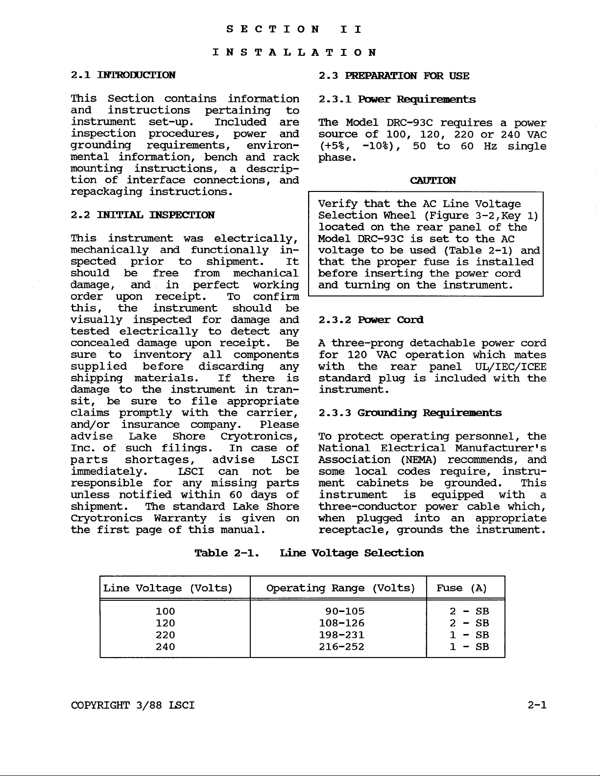
damage, and in perfect working
Verify that the AC Line Voltage
Selection Wheel (Figure 3-2,Key
located on the rear panel
Model DRC-93C is set to the
voltage to be used (Table
that the proper fuse
is
of
the
AC
2-1)
installed
before inserting the power cord
and turning on the instrument.
1)
and
Line Voltage (Volts)
COPYRIGHT
100
220
240
3/88
120
Operating Range (Volts)
90-105
108-126
198-231
216-252
Fuse (A)
2
-
SB
2
-
SB
1
-
SB
1
-
SB
LSCI 2-1
Section
II
Model
DRC-93C
2.3.4
Bench
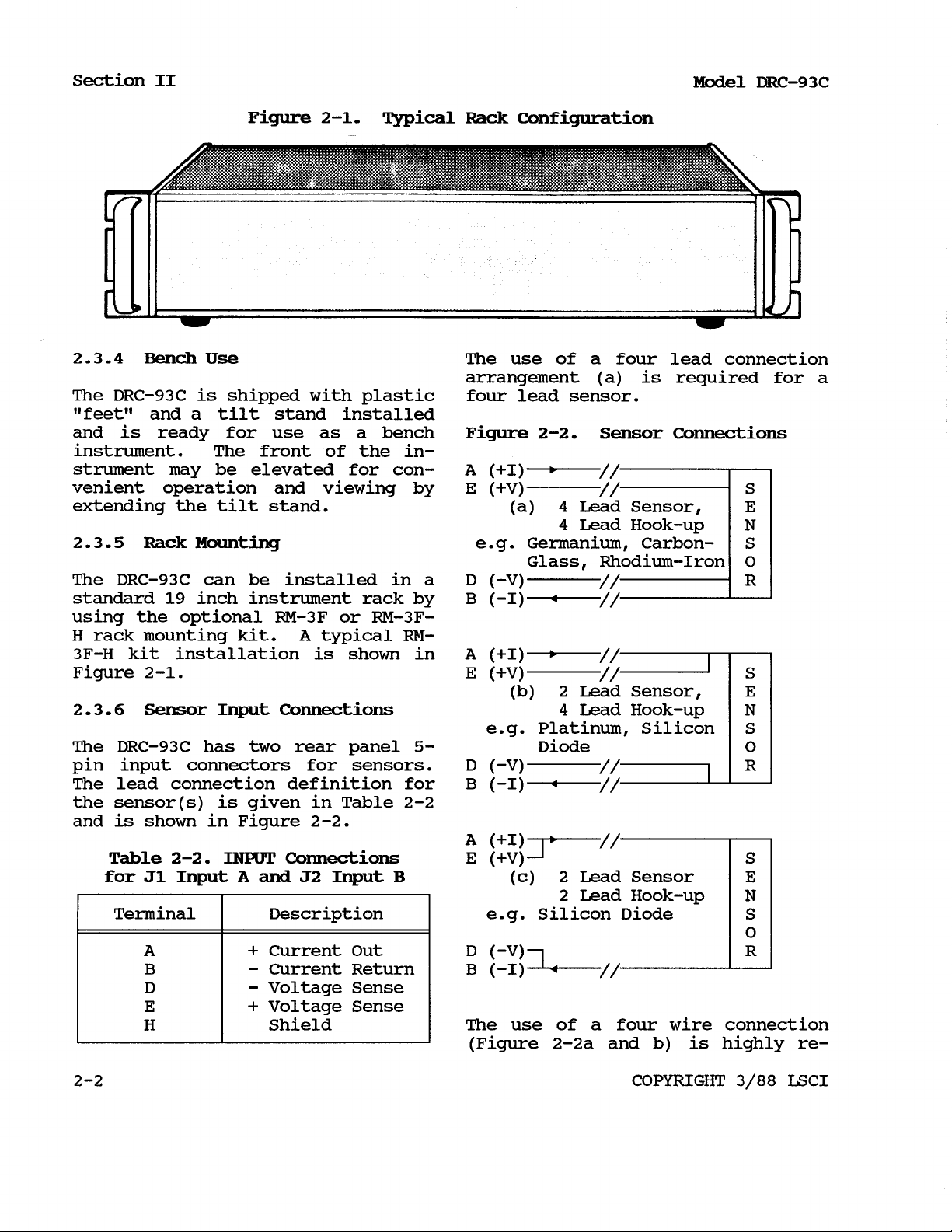
Figure
Use
2-1.
Typical
The DRC-93C is shipped with plastic
“feet” and a tilt stand installed
and is ready for use as a bench
instrument. The front of the instrument may be elevated for convenient operation and viewing by
extending the tilt stand.
2.3.5
Rack Mounting
The DRC-93C can be installed in a
standard
19
inch instrument rack by
using the optional RM-3F or RM-3FH rack mounting kit.
A
typical
RM-
3F-H kit installation is shown in
Figure
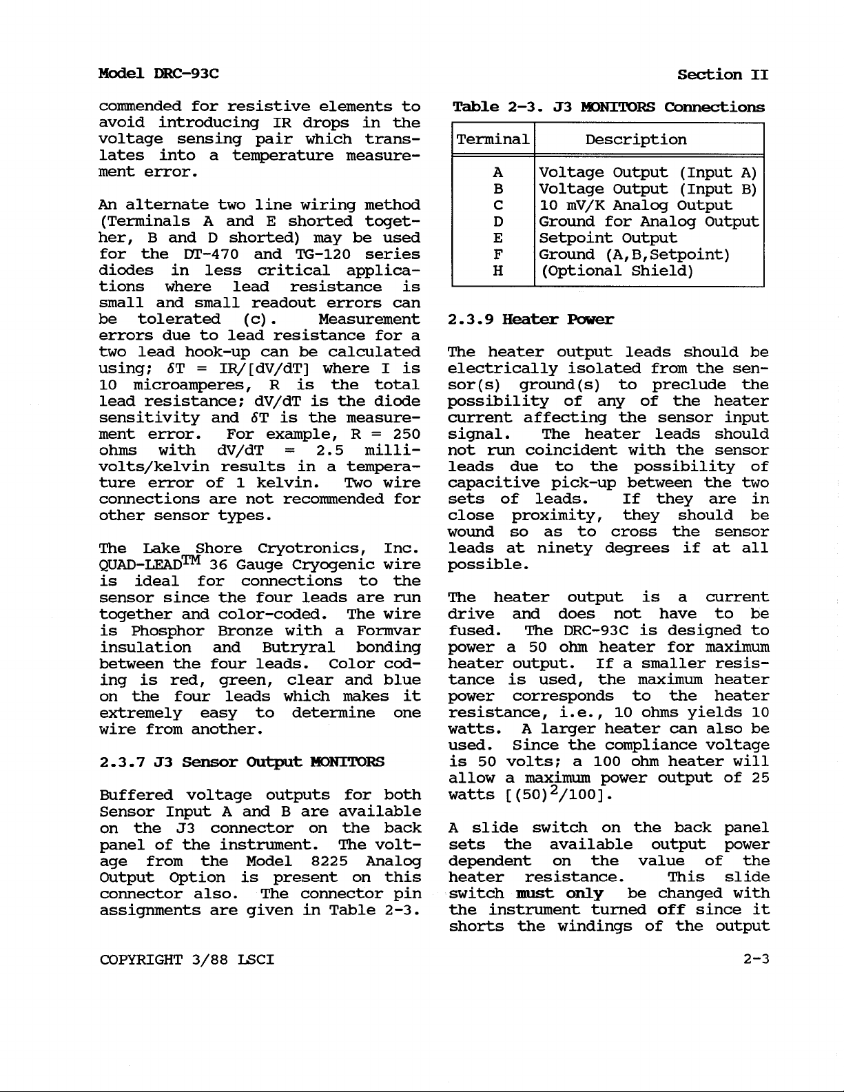
2.3.6
The DRC-93C has
2-1.
Sensor
Input
Connections
two
rear panel
5-
pin input connectors for sensors.
The lead connection definition for
the sensor(s) is given in Table
and
is shown in Figure
Table
for
J1
2-2.
Input
INPUT
A
and
Terminal
A
B
D
E
+
-
-
+
H
2-2.
Connections
J2
Input
Description
Current Out
Current Return
Voltage Sense
Voltage Sense
Shield
2-2
B
Rack
Configuration
The use of a four lead connectio
arrangement (a) is required for
four lead sensor.
Figure
A
(+I)
E
(+V)
e.g. Germanium, Carbon-
D (-V)
B
(-I)
A
(+I)
E
(+V)
e.g. Platinum, Silicon
D (-V)
B
(-I)
A
(+I)
E
(+V)
e.g. Silicon Diode
D
(-V)
B
(-I)
2-2.
(a)
Sensor
4
Lead Sensor,
4
Lead Hook-up
Connections
Glass, Rhodium-Iron
(b) 2 Lead Sensor,
4
Lead Hook-up
Diode
(c)
2
Lead Sensor
2
Lead Hook-up
S
E
N
S
O
R
S
E
N
S
O
R
S
E
N
S
O
R
The use of a four wire connection
(Figure
2-2a
and b) is highly re-
2
-2
COPYRIGHT
3/88
LSCI
Model
DRC-93C
Section
II
commended for resistive elements to
Table
2-3. J3
MONITORS
Connections
avoid introducing IR drops in the
voltage sensing pair which trans-
Terminal
Description
lates into a temperature measure-
ment error.
An alternate two line wiring method
(Terminals
her,
B
for the
A
and
E
shorted toget-
and D shorted) may be used
DT-470
and
TG-120
series
diodes in less critical applica-
A
B
C
D
E
F
H
Voltage Output (Input
A)
Voltage Output (Input B)
10
mV/K Analog Output
Ground for Analog Output
Setpoint Output
Ground
(A,
B,
Setpoint)
(Optional Shield)
tions where lead resistance is
small and small readout errors can
be
tolerated (c). Measurement
2.3.9
Heater
Power
errors due to lead resistance for a
two lead hook-up can
using; §T
10
microamperes, R is the total sor(s) ground(s) to preclude the
=
IR/[dV/dT] where I is electrically isolated from the sen-
be
calculated The heater output leads should be
lead resistance; dV/dT is the diode possibility of any of the heater
sensitivity and §T is the measure- current affecting the sensor input
ment error. For example, R
ohms with dV/dT
=
2.5
=
250
signal. The heater leads should
milli- not
run
coincident with the sensor
volts/kelvin results in a tempera- leads due to the possibility of
ture error of
1
kelvin.
Two
wire capacitive pick-up between the two
connections are not recommended for sets of leads. If they are in
other sensor types. close proximity, they should be
wound
so
as to cross the sensor
The Lake Shore Cryotronics, Inc. leads at ninety degrees if at all
QUAD-LEAD™
36
Gauge Cryogenic wire possible.
is ideal for connections to the
sensor since the four leads are run The heater output is a current
together and color-coded. The wire drive and does not have to be
is
Phosphor Bronze with a Formvar fused. The DRC-93C is designed to
insulation and Butryral bonding power a
between the
four
leads. Color cod- heater output. If a smaller resis-
50
ohm
heater for maximum
ing is red, green, clear and blue tance is used, the maximum heater
on the four leads which makes it power corresponds to the heater
extremely easy to determine one resistance, i.e.,
wire from another. watts.
A
larger heater can also be
10
ohms
yields
10
used. Since the compliance voltage
2-3.7 J3
Buffered voltage outputs for both watts
Sensor
Output
MONITORS
is
50
volts; a
100
ohm
heater will
allow a maximum power output of
[
(50)
2/100].
25
Sensor Input A and B are available
A
on the J3 connector on the back
slide switch on the back panel
panel of the instrument. The volt- sets the available output power
age from the Model
8225
Output Option is present
connector also. The connector pin switch
assignments are given in Table
Analog dependent on the value
on
this heater resistance. This slide
2-3.
must
the instrument turned
only
be changed with
off
since it
of
the
shorts the windings of the output
COPYRIGHT
3/88
LSCI
2-3

Section
II
Model
DRC-93C
transformer between positions.
The setting range of the switch
should coincide with the heater
resistance to minimize power dissipated within the DRC-93C. Three
setting ranges are available:
25,
25-35
An
optional output power stage
(W60) of
and
35
to 50
60
watts is available for
ohms.
10-
the DRC-93C. The W60 is rated at
1.5
volts
A
amperes at approximately
50
(into
ohm,
50
25
ohm
watt
load).
(1/4"
dia.
x
43
1"
long) cartridge heater is available
as well as a
dia.
A
x
1”
30
gauge stranded copper lead
25
ohm,
25 watt
(3/8"
long) cartridge heater.
wire (ND-30) is recommended for
connecting to the heater.
2.3.9.1
Make sure that the
MAX
HEATER
POWER
MAX
Limit
HEATER POWER
limit potentiometer is turned fully
clockwise during the setup of the
instrument
available on the
if
desired.
2.3.9.2
so
Current
that full power
MAX
power scale,
or
Power
Output
is
Display
The HEATER
read either
%
meter can be set to
%
of output power or
%
of output current. The internal
DIP switch setting (switch
trols whether the meter reads in
1)
con-
%
current (closed) or % power (open).
The DRC-93C is shipped to read in
%
power.
2.4
REMOTE
SENSOR
ID
Connector
The REMOTE SENSOR ID connector, J5,
on the rear panel receives POSITION
DATA from a Model
8084
or
8085
Sensor Scanner or a Model SW-10A
Ten-Sensor Selector Switch. The
REMOTE SENSOR ID Interconnecting
Cable and REMOTE SENSOR ID connector assignments are given in Table
2-4.
Table
2-4.
REMOTE
Connector
SENSOR
Assignments
ID
REMOTE SENSOR ID
Connector Pin
10
8
6
4
14
12
Function
Bit 0 (BO-LSB)
Bit
1
(B1)
Bit
2
(B2)
Bit
3
(B3)
4
Bit
(B4-MSB)
Digital Ground
The POSITION DATA is the binary
representation of the remote posi-
2-4
tion. Table
gives the POSITION
DATA binary combinations and
equivalent hexadecimal remote position. The remote position input
can be used to select specific
sensor curve tables stored in the
DRC-93C. The correlation between
remote position and sensor curve is
given in Section
2.5
IEEE-488
III.
INTERFACE
Connector
The IEEE-488 Connector on the back
in
of the DRC-93C is
full compli-
ance with the IEEE Standard
488-1978.
The connector has metric
threaded mounting studs, visually
indicated by the color black.
Metric threaded cable lockscrews
(also black) must
an
IEEE-488 interface cable to the
instrument. Model
be
used to secure
8072
IEEE-488
Interconnect Cables (one meter
long) are available from Lake
Shore.
2-4
COPYRIGHT
3/88
LSCI
Model
2.6
Options
DRC-93c
2.7
ENVIRONMENTAL
Section
REQUIREMENTS
II
2 . 6.1 8223 Rs-232C
Interface.
WARNING
Provides remote operation of the
same parameters as the
The
RS-232C
interface option is
described in Section
manual including connections.
2.6.2 8225
Analog
Output.
analog output proportional to kel-
IEEE-488.
VII
Provides
of this
To
prevent
shock
the instrument
excess
2.7.1
hazards,
moisture.
Operating Temperature
electrical
do
to
not
rain
fire
expose
or
or
vin temperature f display sensor
(10mV/K)
tance. The
described in Section
manual.
2.6.3 8229
at
<10
ohms
8225
Scanner
output resis- In order to meet and maintain the
Analog Output is specifications in Table
VII
of this
DRC-93C
should be operated at an
1-1,
ambient temperature range of
Input Option.
5°C.
outside the range of
The unit may be operated
15-35°C
the
23°C
with
±
Adds four additional channels to less accuracy.
the “A” input. Scans up to six
sensors with programmable dwell
times. The
described in Section
Section
VII
8229
Scanner Option is
III
and The
of this manual. and no humidity or altitude speci-
2.7. 2
Humidity/Altitude
DRC-93C
is for laboratory use
f ications have been determined for
2.6.4
The
High
Resolution
Set
Point
this unit.
expands the set point resolution to
0.01
kelvin below
voltage is expanded
volts out of
kelvin above
100K.
3
volts full scale.
100K
and
0.001
The equivalent
to
25
micro-
2.8
REPACKAGING
If
the Model
FOR
DRC-93C
SHIPMENT
appears to be
This results is a setability of operating incorrectly, refer to the
approximately
and
0.001
DT-470
series sensors. there is a fault with the instru-
0.01
kelvin above
kelvin below
28K
40K
for the
Troubleshooting Guide in Section
5.7.
If
the tests indicate that
ment, contact Lake Shore or a fac-
2.6.5 8001
tom programming of specific Sensor
calibration curve
Precision Option.
(s)
at factory. before returning the instrument.
Cus-
tory representative for a returned
Goods
Authorization
(RGA)
number
Provides highest degree of readout
accuracy. when returning an instrument for
service, photocopy and complete the
2.6.6
deliver
approximately
ohm
installed option.
The
W60
60
watts at
Output Option
1.5
43
volts into a
will Service
Form
found at the beginning
amperes at of Appendix A. The form must be
25
filled in to ensure efficient solu-
load. This is a factory tion of the problem. The following
information must be provided before
Lake Shore will attempt any repair.
COPYRIGHT
3/88 LSCI 2-5
Section
1.
Instrument Model and Serial
2.
User
II
‘
s
Name, Company, Address,
#s
and Phone Number
3.
Malfunction Symptoms
4.
Description
5.
Returned
If
the
original carton is avail-
of
Goods
system
Authorization No.
able, repack the instrument in a
plastic bag, place it in the carton
using original spacers to protect
protruding controls. Seal the
carton with strong paper or nylon
tape. Affix shipping labels and
“FRAGILE”
If
the original carton is not
warnings.
available, pack the instrument
similar to the above,, procedure,
being careful to use spacers or
suitable packing material on all
sides
of
the instrument.
Model
DRC-93C
2-6
COPYRIGHT
3/88
LSCI
3.1
INTRODUCTION
SECTION
OPERATING INSTRUCTIONS
III
e.g., both a diode thermometer and a
resistance thermometer can be used
This section contains information on the two inputs. Another possibil-
and instructions concerning the ity with the 9318C and
9220
Options
operation of the Model DRC-93C Temp- would be the presence of a GR-200A
erature Controller. Included is a Series Germanium Sensor as well as a
description of the front and rear
PT-100
Series Platinum Resistance
panel controls and indicators. Sensor. Both inputs are updated
independently, which allows them
both to be displayed or queried
3.2
INSTRUMENT
CONFIGURATION
under
IEEE-488
or RS-232C control.
The addition of an optional 8229
3.2.1
Input
Card
Configurations
Sensor Scanner Card adds capability
4
for
additional inputs to the
A
The Model DRC-93C can be used with channel resulting in up to 5 sensors
either one or two input cards. The of the same type being allowed using
input cards available for use with the A input card.
the DRC-93C are summarized in Section
I.
The input cards available
3.2.4
Old
Version
Input
Cards
allow the 93C to be used with almost
any type of cryogenic sensor. Input The
8210,
8211 diode input cards can
cards can be mixed, allowing two be used in the 93C as well as the
different sensor types to be used
8219
series resistance input card.
with the DRC-93C. The installation of these cards is
3.2.2
Single
Input
Card
covered in Section
manual. Note that there are Dip
7-3
of
this
Switch settings on the main board
When only one input card is present which must be set in order for these
within the unit, it occupies the older cards to work properly.
INPUT
CARD
#1
slot of the DRC-93C
mainframe and is connected to the
Sensor
A
input of the controller.
3.3
CURVE
ENTRY
Only one sensor can be used with the
controller under these conditions.
3.2.3
Dual
Input
Cards
When two input cards are present in curve entry via the
the unit, the input card that oc- Section
cupies the INPUT CARD
routed to the Sensor
#1
slot is
A
input and the The curve is stored in a battery
input card that occupies the INPUT back-up non-volatile
CARD
B
#2
slot is routed to the Sensor which can be read and written an
input. Consequently, both sensors unlimited number
are energized at all times.
The DRC-93C allows the user to enter
his
own
front panel
terface. Section
sensor calibration via the
or
over the remote in-
3.9.3
discusses
front panel and
IV
covers entry over the
IEEE-488
or RS-232C interfaces.
RAM
of
times. The num-
(NOVRAM)
ber of data points stored per curve
can be between
2
and 97; two being
The second input card allows the the lower limit which defines a
instrument to mix sensor types, straight line.
COPYRIGHT
3/88
3-1
Section
3.4
III
PRECISION OPTIONS
Model
DRC-93C
and with which input the sensor will
be associated if remote operation is
3.4.1
option
The
Model
8000
Precision
used.
3.5
CONTROL
FUNDAMENTALS
There are three types of Precision
Options available for the DRC-93C. An application note entitled
The Model
generates the data table
8000
Precision Option “Fundamentals for Usage of Cryogenic
from a Lake Temperature Controllers" is included
Shore calibrated sensor. The upper as an appendix in this manual and
limit of data points is again 97, should
be
read in detail if you are
with a typical calibration ranging not familiar with cryogenic temperabetween
30
and
40
points, depending ture controllers.
on sensor type and temperature range
for the calibration. The data and
accuracy of the fit is supplied to
3.6
CONTROLS
AND
INDICATORS
the user as a separate document.
This information can then be entered Figures
3-1
and
3-2
identify the
by the user via the front panel or DRC-93C displays, annunciators, conover the computer interface. trols, and connectors. The iden-
tification of each item is keyed to
3.4.2
option
The
Model
8001
Precision
the appropriate figure.
Lake Shore can also generate custom
FRONT
PANEL
DESCRIPTION
sensor response curves from the individual sensor calibrations as
3.7
POWER
ON
indicated above and store them in
the DRC-93C via the
8001
Precision Before connecting AC power to the
Option prior to shipment. The data DRC-93C, make sure the rear panel
and accuracy of the fit is then voltage selector is set
to
corre-
supplied to the user in an Appendix spond to the available power line
of this manual. voltage. Be certain the correct
fuse is installed in the instrument.
3.4.3 The Model 8002-05
option
The
8002
Precision Option is used Immediately on
when the customer already
DRC-93C and wants new sensor cali- follows
Precision
owns
a
3.7.1
runs
Power
Up
Sequence
POWER
ON the DRC-93C
through a power up sequence as
:
bration data stored in the instru-
1.
ment. LSCI stores the calibration
data in a PROM chip
and
sends the
programmed chip to the customer.
The PROM is then installed in the bar graph turn on to test
Light Test
All
digits, annunciators, and the
the
DRC-93C by the customer. lights.
Note that additional calibrations The TEMPERATURE Block indicates
can be added to the instrument at a +8.8.8.8.8. in both the upper,
later time by specifying with the
sensor calibration at time of order, CONTROL Block indicates
the serial number of the instrument GAIN, RATE, and
lower and setpoint windows. The
RESET
8.8.
windows. The
in the
3
-2
COPYRIGHT
3/88
Model
DRC-93C
Section
III
HEATER
100%.
SENSORS
POWER
Bar Graph indicates (switch
The UPPER and
have
8.
The indicators for dating is enabled (switch 2 on) at
LOWER
2)
controls whether or not
DISPLAY the settings are updated. The up-
the six sets of UNITS for both the the factory prior to shipment.
Upper and Lower displays are displayed to the far left of the front
panel. The control
(CTRL)
annun-
3.7.3
Blue
Legend
Keys
ciators are between the SENSOR an-
OFF
nunciators. The RANGE from
MAX
annunciators are below the Bar one of the grey keys of the keypad
graph and the
(programming) and
LOCAL,
REMOTE, PROG with Blue Legends (also labelled
INT
(internal
program) to the far right of the described by the blue legend is
to At the beginning of an operation, if
0-
9,
and
.)
is pressed, the function
im-
front panel. mediately displayed or carried out.
These functions are SENSOR, UNITS,
2.
Instrument Name and IEEE Address
CURVE#,
MATH,
RSLTN, FILTER, CONTROL,
MAX, MIN, MAXDEV.
DEV,
Next the unit displays LSCI in the
Upper Display, -93C- in the Setpoint The
Display and the IEEE-488 interface
address in the Lower Display.
factory set IEEE address of
For a
12
the quantity continuously.
MATH,
be held down
CURVE#,
MAX,
display would indicate Add12. This ample, if the
address can obviously be changed by is pressed, the display will
MIN,
in
RSLTN
RSLTN,
FILTER,
DEV,
and MAXDEV keys must
order to observe the
For ex-
(resolution) key
im-
the user and verification of that mediately show the resolution aschange is always given on power-up. signed to the Upper and Lower Dis-
Note that this address is only read plays. When the key is let up,
by the instrument on power-up operation will return to normal
operation with the displays showing
3.
Input Card Configuration temperature, voltage, etc.
The unit then displays the input
cards associated with the inputs on
the upper and the lower displays.
The CONTROL, SENSOR,
UNITS,
RSLTN, FILTER, DEV, and
provide operations that can be
CURVE#,
MATH
keys
changed by the user. The (up)
4.
Normal
Operation and (down) keys are used in con-
junction with these Blue Legend keys
The unit then goes into normal to alter the quantity with the
operation. key referring to the Upper Display
and the key referring to the
3.7.2
Power-up
Status
Lower Displays. In order to change
one of these quantities it is neces-
A
provision has been made to store sary to hold the Blue Legend key
parameter changes in the DRC-93C down while hitting the (up) key
memory (NOVRAM)
.
The sample and or (down) key. The key will
control units, as well as the curve change the entry of the Upper disnumbers and scan dwell times can be play and the key will change the
stored as power-up settings. When Lower display.
enabled, any time the parameter is
changed, either in the LOCAL or
REMOTE mode, the NOVRAM is updated.
The internal DIP switch setting
COPYRIGHT
3/88
3-3
Section
III
Model
DRC-93C
Figure
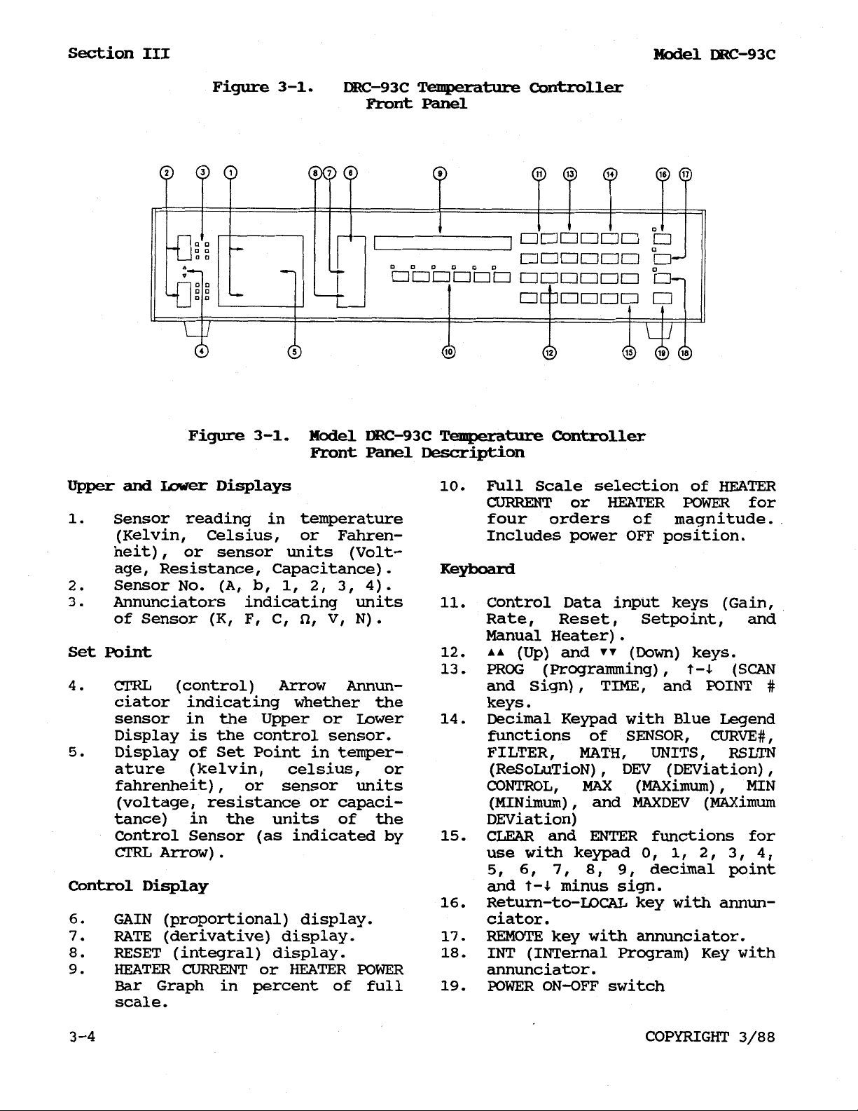
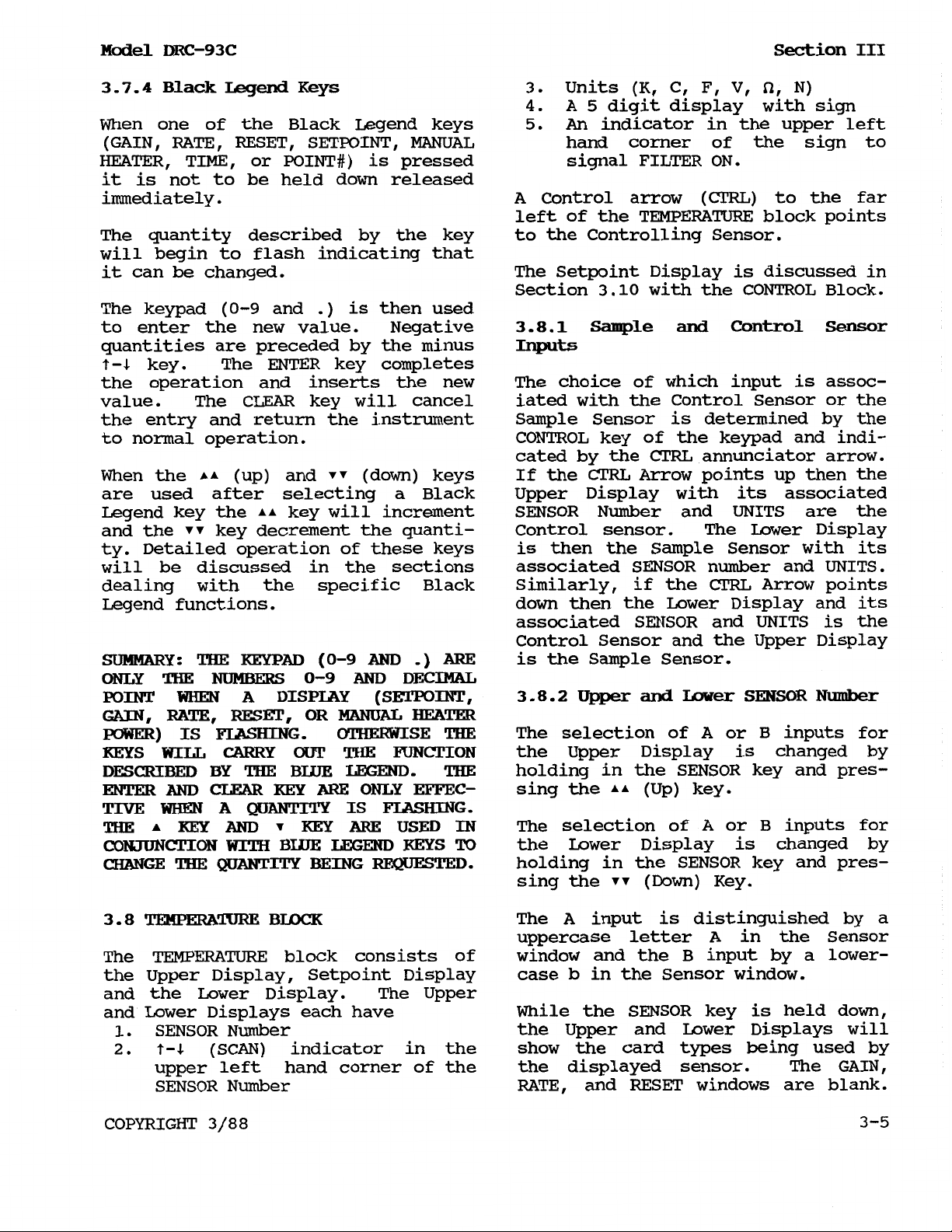
Upper
1.
and
laver Displays
Sensor reading in temperature four orders of magnitude.
(Kelvin, Celsius, or Fahren- Includes power OFF position.
heit), or sensor units (Voltage, Resistance, Capacitance)
2.
3.
Sensor No.
Annunciators indicating units
of Sensor (K,
Set
Point
4.
CTRL
(control) Arrow
ciator indicating whether the keys.
sensor in the Upper or Lower
Display is the control sensor. functions of SENSOR,
5.
Display of Set Point in temper- FILTER, MATH,
ature (kelvin, celsius, or (ReSoLuTioN) , DEV (DEViation)
fahrenheit), or sensor units
(voltage, resistance or capaci- (MINinum), and MAXDEV (MAXimum
tance) in the units
Control Sensor (as indicated by
CTRL
Arrow). use with keypad
Control Display
6.
7.
8.
9.
GAIN (proportional) display. ciator.
RATE
RESET
HEATER
(derivative) display.
(integral) display.
CURRENT
Bar Graph in percent of full
scale.
Figure
3-1-
(A,
b,
F,
or HEATER POWER annunciator.
3-1. DRC-93C
Front Panel
1,
C,
Model
Front
2,
DRC-93C
Panel Description
3,
4).
V,
N). Rate, Reset, Setpoint, and
Annun-
of
the DEViat ion)
Temperature
Temperature
10.
.
Keyboard
11.
12.
13.
14.
15.
16.
17.
18.
19.
Controller
controller
Full Scale selection of HEATER
CURRENT
or
HEATER
POWER
for
Control Data input keys (Gain,
Manual Heater).
(Up) and
PROG
and
(Programming),
Sign), TIME,
(Down)
and
keys.
(SCAN
POINT
#
Decimal Keypad with Blue Legend
CURVE#,
UNITS,
RSLTN
,
CONTROL,
CLEAR and ENTER functions for
5,
6,
and minus sign.
Return-to-LOCAL key with annun-
REMOTE
INT (INTernal Program) Key with
POWER ON-OFF switch
7,
MAX
8,
(MAXimum),
0,
1,
2,
9,
decimal point
3, 4,
key with annunciator.
MIN
3
-4
COPYRIGHT
3/88
Model
DRC-93C
Section
III
3.7.4
When one of the Black Legend keys
(GAIN, RATE, RESET, SETPOINT,
Black
Legend
Keys
MANUAL
3.
Units (K, C, F,
4.
A
5
digit display with sign
5.
An
indicator in the upper left
V,
N)
hand corner of the sign to
HEATER, TIME, or POINT#) is pressed signal FILTER ON.
it is not to be held down released
immediately. A Control arrow
(CTRL)
to the far
left of the TEMPERATURE block points
The quantity described by the key to the Controlling Sensor.
will begin to flash indicating that
it can
The keypad
be
changed.
(0-9
and
.)
is then used
to enter the new value. Negative
quantities are preceded by the minus
key. The
ENTER
key completes
the operation and inserts the new The choice
value. The
CLEAR
key will cancel iated with the Control Sensor or the
The Setpoint Display is discussed in
Section
3.8.1
Inputs
3.10
Sample
of
with the CONTROL Block.
and
Control
Sensor
which input is assoc-
the entry and return the instrument Sample Sensor is determined by the
to normal operation.
CONTROL key
cated by the
When the (up) and (down) keys If the
CTRL
of
the keypad and indi-
CTRL
annunciator arrow.
Arrow points up then the
are used after selecting a Black Upper Display with its associated
Legend key the key will increment SENSOR Number and UNITS are the
and the key decrement the quanti- Control sensor. The Lower Display
ty. Detailed operation
will be discussed in the sections associated
dealing with the specific Black Similarly, if the
Legend functions.
of
these keys is then the Sample Sensor with its
SENSOR
down then the
number and UNITS.
CTRL
Arrow points
Lower Display and its
associated SENSOR and UNITS is the
Control Sensor and the Upper Display
SUMMARY:
ONLY
POINT
GAIN,
POWER)
KEYS
DESCRIBED
ENTER
TIVE
THE
CONJUNCTION
CHANGE
THE
THE
WHEN
RATE,
IS
WILL
AND
WHEN
KEY
THE
KEYPAD
NUMBERS
A
DISPLAY
RESET,
FLASHING
CARRY
BY
THE
CLEAR
A
KEY
QUANTITY
AND
WITH
QUANTITY
BLUE
(0-9
0-9
OR MANUAL HEATER
OUT
BLUE
ARE
KEY
BEING
AND
.)
AND
DECIMAL
(SETPOINT,
OTHERWISE
THE
FUNCTION
LEGEND.
ONLY
IS
ARE
LEGEND
EFFEC-
FLASHING.
USED
KEYS
REQUESTED.
ARE,
THE
THE
IN
To
is the Sample Sensor.
3.8.2
The selection
the Upper Display is changed
Upper
and
of
Lower
SENSOR
A
or B inputs for
Number
by
holding in the SENSOR key and pres-
sing the (Up) key.
The selection of A or B inputs for
the Lower Display is changed by
holding
in the SENSOR key and pres-
sing the (Down) Key.
3.8
TEMPERATURE
The
TEMPERATURE
the Upper Display, Setpoint Display
BLOCK
The
A
input is distinguished by a
uppercase letter
A
in the Sensor
block consists of window and the B input by a lower-
case
b
in the Sensor window.
and the Lower Display. The Upper
and Lower Displays each have While the SENSOR key is held down,
1.
SENSOR Number
2.
(SCAN) indicator in the show the card types being used
the Upper and Lower Displays will
by
upper left hand corner of the the displayed sensor. The GAIN,
SENSOR Number
COPYRIGHT
RATE, and
3/88 3-5
RESET
windows are blank.
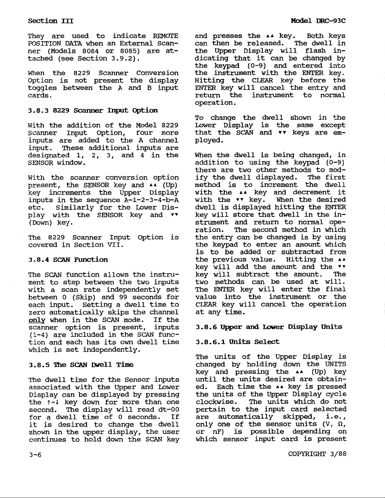
Section
III
Model
DRC-93C
They are used to indicate REMOTE and presses the key. Both keys
be
POSITION DATA when an External Scan- can then
ner (Models
tached (see Section
8084
or
3.9.2).
8085)
are at- the Upper Display will flash in-
dicating that it can be changed by
the keypad
When the
8229
Scanner Conversion the instrument with the ENTER key.
Option is not present the display Hitting the
toggles between the
A
and
B
input ENTER key will cancel the entry and
released. The dwell in
(0-9)
CLEAR
and entered into
key before the
cards. return the instrument to normal
operation.
3.8.3 8229
Scanner
Input
Option
To change the dwell shown in the
With the addition of the Model
8229
Scanner Input Option, four more that the
inputs are added
to
the A channel ployed.
Lower Display is the same except
SCAN
and keys are em-
input. These additional inputs are
1,
2,
3,
designated
and
SENSOR window. addition to using the keypad
4
in the When the dwell is being changed, in
(0-9)
there are two other methods to mod-
With the scanner conversion option ify the dwell displayed. The first
present, the SENSOR key and (Up) method is to increment the dwell
key increments the Upper Display with the key and decrement it
inputs in the sequence
etc. Similarly for the Lower Dis- dwell is displayed hitting the
A-1-2-3-4-b-A
with the key. When the desired
ENTER
play with the SENSOR key and key will store that dwell in the in-
(Down)
key. strument and return to normal ope-
ration. The second method in which
The
8229
covered in Section VII.
Scanner Input option is the entry can be changed is by using
the keypad to enter an amount which
is to be added or subtracted from
3.8.4
SCAN
Function
the previous value. Hitting the
key will add the amount and the
The
SCAN
ment to step between the two inputs two methods can
function allows the instru- key will subtract the amount. The
be
used at will.
with a scan rate independently set The ENTER key will enter the final
between
each input.
zero automatically skips the channel
only
scanner option is present, inputs
(1-4)
tion
0
(Skip) and
99
seconds for value into the instrument or the
Setting a dwell time to CLEAR key will cancel the operation
when in the SCAN mode. If the
are included in the
and
each has its
SCAN
own
dwell time
func-
at any time.
3.8.6
3.8.6.1Units
Upper
and
Select
Lower
Display
Units
which is set independently.
The units of the Upper Display is
3.8.5
The
SCAN
Dwell
Time
changed by holding down the UNITS
key and pressing the (Up) key
The dwell time for the Sensor inputs until the units desired are obtainassociated with the Upper and Lower ed.
Display can be displayed by pressing
the units of the Upper Display cycle
Each time the key is pressed
the key down for more than one clockwise. The units which do not
second. The display will read dt-00 pertain to the input card selected
for a dwell time of
it is desired to change the dwell only one of the sensor units
0
seconds. If are automatically skipped, i . e.
,
(V,
shown in the upper display, the user or nF) is possible depending on
continues to hold down the SCAN key which sensor input card
is
present
3-6
COPYRIGHT
3/88
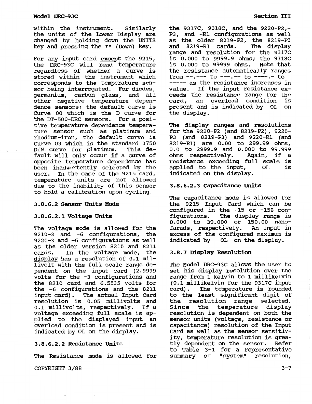
Model
DRC-93C
Section
III
within the instrument. Similarly the 9317C, 9318C, and the 9220-P2,the units of the Lower Display are P3, and -R1 configurations as well
changed by holding down the UNITS as the older 8219-P2, the 8219-P3
key and pressing the
(Down)
key. and 8219-R1 cards. The display
range and resolution for the 9317C
For any input card
except
the DRC-93C will read temperature is
the
9215,
is
0.000
0.000
to
to
9999.9
99999
ohms; the 9318C
ohms.
Note that
regardless of whether a curve is the resistance automatically ranges
stored within the instrument which from
corresponds to the temperature sen-
-----
--.---
to
---
--
----
as the resistance increases in
.
-
to
to
sor being interrogated. For diodes, value. If the input resistance ex-
germanium, carbon glass, and all ceeds the resistance range for the
other negative temperature depen- card, an overload condition is
dence sensors; the default curve is present and is indicated by
Curve
the DT-500-DRC sensors.
00
which is the D curve for the display.
For a posi-
OL
on
tive temperature dependence tempera- The display ranges and resolutions
ture sensor such as platinum and for the 9220-P2 (and 8219-P2),
rhodium-iron, the default curve
Curve
03
which is the standard
DIN curve for platinum. This de-
fault will only occur
if
a curve of
is
3750
P3 (and
8219-P3)
8219-R1) are
0.0
to
2999.9
ohms
respectively. Again, if a
and 9220-R1 (and
0.00
and
to
0.000
299.99
to
9220-
ohms,
99.999
opposite temperature dependence has resistance exceeding full scale is
been inadvertently selected by the applied to the input,
user. In the case of the
9215
card,
indicated on the display.
OL
is
temperature units are not allowed
due to the inability of this sensor
3.8.6.2.3
Capacitance
Units
to hold a calibration upon cycling.
The capacitance mode is allowed for
3.8.6.2
3.8.6.2.1Voltage
The voltage mode is allowed for the farads, respectively.
9210-3
9220-3
as the older version
cards. In the voltage mode, the
display has a resolution of
livolt with the full scale range dependent on the input card
volts for the
the
the
Sensor
Units
Mode
Units figurations. The display range is
and
and
8210
-6
configurations and the
-6
configurations, the excess of the configured maximum is
-6
configurations as well indicated by
8210
-3
configurations and range from 1 kelvin to 1 millikelvin
card and 6.5535 volts for (0.1
and
0.1
(2.9999
8211
mil-
8211
the
configured in the -15 or
0.000
3.8.7
9215
Input Card which can be
to
30.000
or
OL
on the display.
Display Resolution
-150
150.00
An
con-
nano-
input in
The Model DRC-93C allows the user to
set his display resolution over the
millikelvin
for the 9317C input
card). The temperature is rounded
input card). The actual Input Card to the least significant digit of
resolution is
0.1
millivolts, respectively. If a Since the temperature display
0.05
millivolts and the resolution range selected.
voltage exceeding full scale is ap- resolution is dependent on both the
plied to the displayed input an sensor units (voltage, resistance or
overload condition is present and is capacitance) resolution of the Input
OL
indicated by
on the display. Card as well as the sensor sensitiv-
ity, temperature resolution is grea-
3.8.6.2.2
The Resistance mode
Resistance
Units
is
allowed for summary of “system” resolution,
tly dependent on the sensor. Refer
to
Table 3-1 for a representative
COPYRIGHT
3/88
3
-7
 Loading...