

Lakeshore DRC-91 C User Manual
USER’S MANUAL
Model
Tem
per
DRC-91
at
u
re
Con
t
ro I ler
C
Obsolete Notice:
This manual describes an obsolete Lake Shore product This manual is a copy from our archives
and may not exactly match your instrument Lake Shore assumes no responsibility for this
manual matching your exact hardware revision or operational procedures. Lake Shore is not
responsible for any repairs made to the instrument based on information from this manual.
Methods
and apparatus disclosed
relationship whatsoever has existed
herein may
be
subject
to U S
poducts
of
this
material
Manual
at any
time
No
Patents existing
without notice
MAN-DRC-91
and
described herein have been developed
which
in
Lake
any way affects
or
Shore
shall
applied
not
or
mitigates proprietary rights
lor
Lake
be
liable
C
Lakeshore.
Lake Shore Cryotronics, Inc.
575
McCorkle Blvd.
Westerville, Ohio 43082-8888
Internet Addresses.
sales@ lakeshore com
service@ lakeshore com
Fax (614) 891-1392
Telephone (614) 891-2243
solely
on
company
funds
of
Lake
Shore
Cryotronics
lor
errors contained herein
Inc reserves
Shore Cryotronlcs
the
or
lor
incidental
of
right
Lake
Shore
to
add
or
consequential
USA
Cryotronlcs
Inc
improve
Inc
No
in
these
modify
damages in connection wth furnishing performance
government
developments
or
withdraw functions deslgn modifications or
or
Methods
other
contractual support
and apparatus
December,
disclosed
1987
Or
Or
use
SERIAL
SOFTWARE
NUMBER
INSTRUCTIO
MODEL
TEMPERATUR
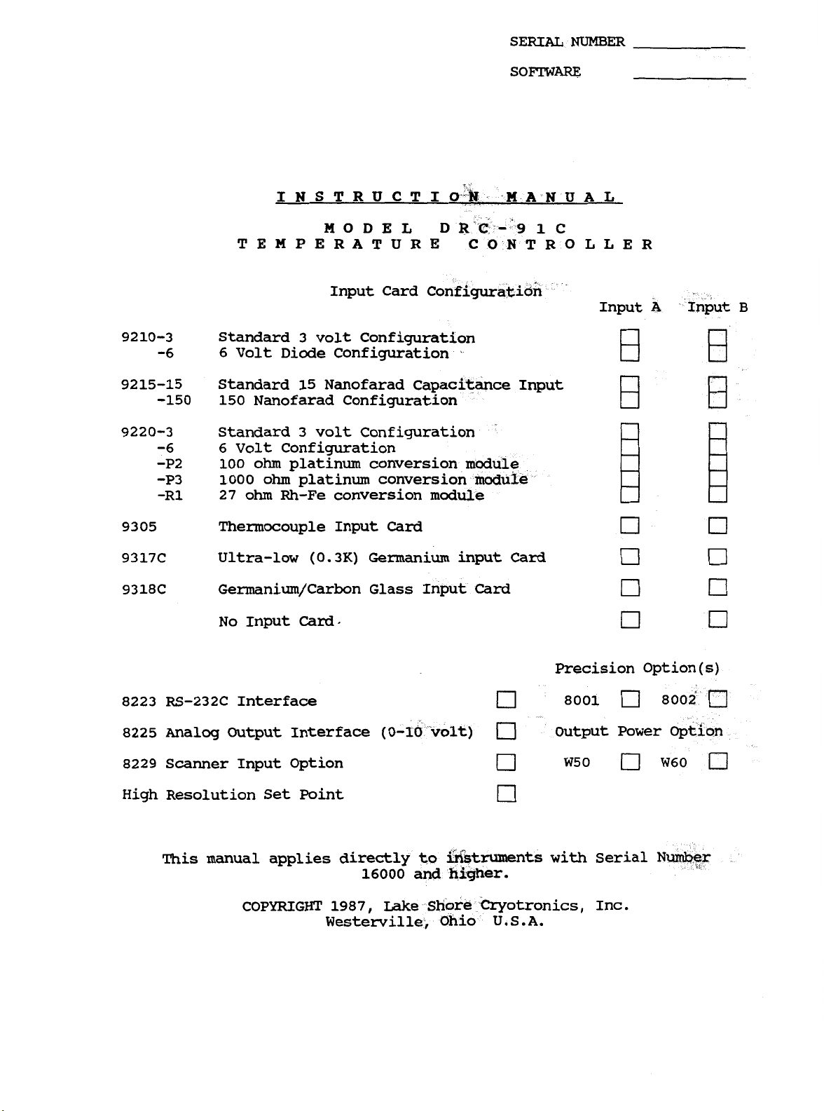
Input Card
92
10-3
-6 6
Standard 3 volt Configuration
Volt Diode Configuration
9215-15 Standard 15 Nanofarad Capac
-150 150 Nanofarad Configuration
9220-3 Standard 3 volt Configuration
-6 6
-P2
-P3
-R1
9305 Thermocouple Input
Volt
100
1000
27
ohm
Configuration
ohm
platinum conversion modul
ohm
platinum conversion modu
Rh-Fe conversion module
Card
9317C Ultra-low (0.3K) Germanium input
9318C Germanium/Carbon Glass I
MANUA
Card
L
ut
B
No
Input
Card
Precision Option(s)
8223 RS-232C Interface 8001 8002
8225 Analog Output Interface
8229 Scanner Input Option
(0-
Output
W50
Power
W60
High Resolution Set Point
This manual applies directly to
16000
and
with Serial
N
nts
COPYRIGHT 1987, Lake Shore Cryotronics, Inc.
Westerville,
Ohio
U.S.A.
WARRANTY
Lake Shore Cryotronics, Inc., the manufacturer, warrants this product
to the owner for a period of
12
months from the date of shipment.
During the warranty period, under authorized return of instruments or
component
or at its option replace,
workmanship without charge to the
parts
to
Lake Shore freight prepaid, the company will repair,
any
part
found to
Owner
for parts, service
be
defective in material or
labor
or
associated customary shipping cost. Replacement or repaired parts will
be
warranted for only the unexpired portion of the original warranty.
All products are thoroughly tested and calibrated to published
specifications prior to shipment. Calibration Certifications are
offered for six month periods only.
updated, a re-certification service
Where such documentation must be
is
offered by
Lake
Shore
Cryotronics, Inc. at a reasonable cost.
LIMITATION
OF
WARRANTY
This warranty does not apply to defects resulting from improper or
inadequate maintenance, unauthorized modification or misuse, operation
outside of the environmental specifications for any product or part
or
buyer-supplied software or interfacing.
THIS
INCLUDING MERCHANTABILITY
ARE
WITH
INCIDENTAL
WARRANTY
IS IN LIEU
EXPRESSLY EXCLUDED.
RESPECT
TO
THIS
OR
CONSEQUENTIAL DAMAGES
PRODUCT
OF
ANY
OTHER
OR
FITNESS
THE
OWNER
SHALL
CERTIFICATION
WARRANTIES, EXPRESSED
FOR
A
PARTICULAR PURPOSE, WHICH
AGREES
BE
ARE
SET
THAT
FORTH
LAKE
IN
SHORE’S
THIS
EXPRESSLY EXCLUDED.
OR
IMPLIED,
LIABILITY
WARRANTY,
AND
Lake Shore Cryotronics, Inc. certifies that this product has been
inspected and tested
and that this product met
in
accordance with its published specifications
its published specifications at the time of
shipment.
The accuracy and calibration of this product at the the of shipment
are traceable to the United States National Bureau of Standards.
Copyright
12/87
TABLE OF CONTENTS
SECTION
1.1
1.2 DESCRIPTION
1.3 SPECIFICATIONS
1.4
SECTION
2.1 INTRODUCTION
2.2 INITIAL INSPECTION
2.3 PREPARATION
2.4
2.5 IEEE-488
2.6 OPTIONS
2.7
2.8
I
-
GENERAL INFORMATION
INTRODUCTION
.
.
OPTIONS
II
...
-
INSTALLATION
....
FOR
USE
2.3.1
2.3.2
2.3.3
2.3.4
2.3.5
2.3.6
2.3.7
2.3.8
2.3.9
REMOTE
Power
Power
Grounding
Bench
Rack
Sensor
J3
SENSOR
Heater
2.3.9.1
2.3.9.2
SENSOR
Mounting
Sensor
Requirements 2-1
Cord
Use
Input
ID
Power
MAX
Current or
ID
Connector
INTERFACE
..........
2.6.1
2.6.2
2.6.3
2.6.4 High Resolution
2.6.5
2.6.6
ENVIRONMENTAL
2.7.1 Operating
2.7.2 Humidity/Altitude
REPACKAGING
The
RS-232C Option
The
The
The
The
8229
8225
8001
W50
FOR
Scanner
Linear
and
and
REQUIREMENTS
SHIPMENT
.
....
Requirements
.......
......
Connections
Output MONITORS
Switches
.
,
...
......
HEATER
POWER
Power
Limit
Output
....
Display 2-5
.
Connector 2-5
.
8002
W60
Option
Analog
Set
Point .
Precision
Power
.
.
Option
Options
Output
Options
.
Temperature
.
,
.
1- 1
1-1
1-3
1-3
2-1
2-1
2-1
2-2
2-2
2-2
2-2
2-2
2-3
2-3
2-4
2-5
2-5
2-6
2-6
2-6
2-6
2-6
2-6
2-6
2-6
2-6
2-6
2-6
SECTION
3.1
3.2
3.3
3.4
3.5
3.6
INTRODUCTION.
INSTRUMENT
3.2.1
3.2.2
3.2.3
3.2.4
CURVE
PRECISION OPTIONS
3.4.1
3.4.2
3.4.3
CONTROL
CONTROLS
III
ENTRY
-
OPERATING INSTRUCTIONS
.........
CONFIGURATION
Input
Single
Dual
Old
Card
Input
Input
Version
Configurations 3-1
Card
Cards
Input
....
...
....
Cards
..........
.......
The
Model
The
Model
The
Model
FUNDAMENTALS.
AND
INDICATORS
8000
8001
6002-05
Precision
Precision
Precision
Option
Option
Option 3-2
.
.
3-1
3-1
3-1
3-1
3-1
3-1
3-2
3-2
3-2
3-2
3
-2
12/87
TABLE
OF
CONTENTS (Cont'd)
3.7
3.8
3.9
3.10
3.11
3.12
POWER ON..
3.7.1
3.7.2
DISPLAY SENSOR
3.8.1
3.8.2 8229
3.8.3
3.8.4
3.8.5
3.8.6
3.8.7
SENSOR
3.9.1
3.9.2
SENSOR
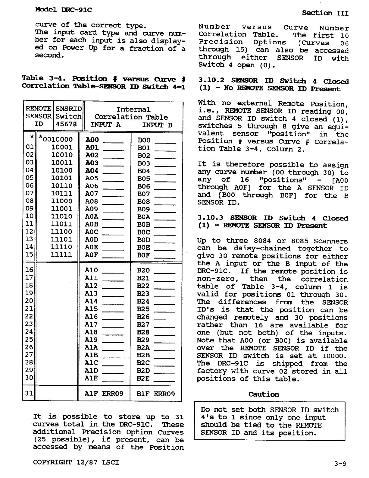
3.10.1
3.10.2
3.10.3
3.10.4
3.10.5
3.10.6
CONTROL
3.11.1
3.11.2
3.11.3
3.11.4
3.11.5
3.11.6
LOCAL/REMOTE
3.12.1
3.12.2
POWER UP
POWER-UP
DISPLAY SENSOR
SCAN
The
DISPLAY
3.8.5.1
3.8.5.2
3.8.5.3
3.8.5.4
3.8.5.5
Display
3.8.6.1
Filtering
CURVES
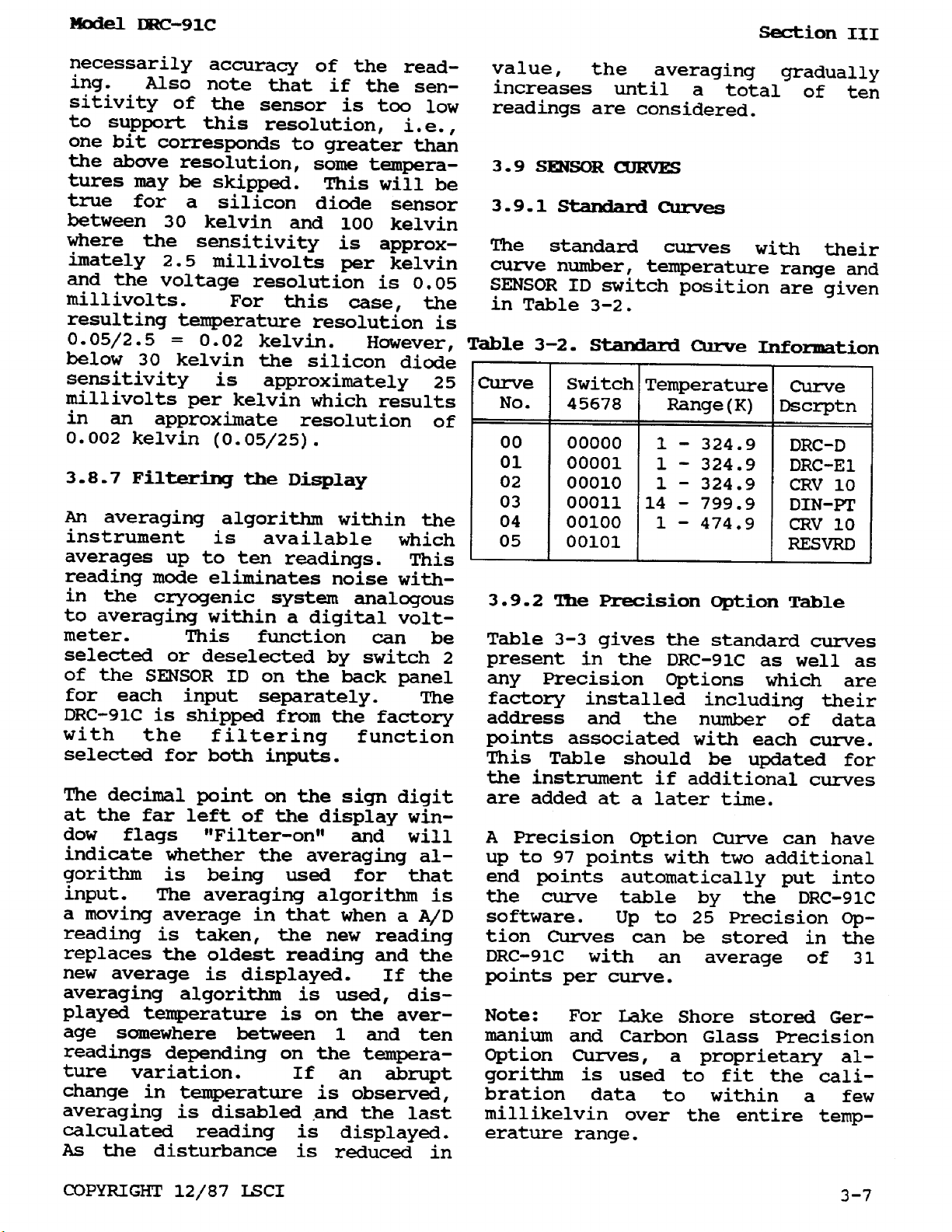
Standard
The
CURVE
SENSOR
3.10.1.1
SENSOR
SENSOR
Addition
Display
Sensor
BLOCK
SET
GAIN
RATE
RESET
HEATER
The
LOCAL
REMOTE
........
Scanner
Function
SCAN
Resolution
Precision
SELECTION
POINT
.
. .
HEATER
BLOCK
FRONT
Sequence
Status
Block
PANEL
.
....
Input
Conversion
.........
Dwell
AND
units
Sensor
Voltage
Resistance
Capacitance
Time
DISPLAY SENSOR
Select
Units
Units
........
Temperature
the
Display
......
Curves
.
Option
......
ID
Switch
Display
ID
Switch
No
ID
Switch
REMOTE
of
of
Curve
REMOTE
8229
Accessed
4
of
4
4
SENSOR
Scanner
assignment
.
.
.
%
.
-
POWER
.
.
RANGE
DESCRIPTION
.
.
option
......
Units
.....
Mode
...
.....
Units
Units
Display
Table
Open
Accessed
Closed
SENSOR
Closed
Position
...
...
Resolution
(0)
curve
(1)
ID
Present
(1)
ID
Present
Option
and
to
Sensor Position
.
Set
....
.........
-
........
-
.........
..........
Assigned
Curve
.....
.
3-10
.
3-10
3-10
3-10
3-10
3-10
3-10
3-11
3-11
3-11
3-11
3-11
3-11
3-2
3-2
3-4
3-4
3-4
3-4
3-4
3-4
3-5
3-5
3-5
3-5
3-5
3-6
3-6
3-6
3-7
3-7
3-7
3-7
3-8
3-8
3-8
3-9
3-9
3.13
3.14
SECTION
4-1. IEEE-488
4.2
4.3
REMOTE
HEATER
GENERAL
INTERFACE CAPABILITIES
SENSOR
CURRENT
IV
-
ID
LIMIT
REMOTE
INTERFACE
IEEE
OPERATION
SPECTFICATIONS
REAR
.
.
.
PANEL DESCRIPTION
.
.
.
.
-
*
.
-
-
AND
OPERATION
.........
.
3-13
3-13
4-1
4-1
4-2
TABLE
OF
CONTENTS (COnt'd)
4.4
4.5 IEEE-488
4.6
4.7
4.8 SELECTION
4.9
4.10
DRC-91C
4.4.1 Terminating Characters (delimiters) 4-3
4.4.2
4.4.3
4.5.1 Uniline Commands 4-5
4.5.2
4.5.3
4.5.4 Unaddress Commands 4-6
4.5.5
4.5.6 Talker and Listener Status
PROGRAMMING
4.6.1 Commands and Requests
INSTRUMENT
4.7.1
4.7.2 Interface Mode
4.7.3 Terminating Characters
4.7.4 Clear
4.7.5 The “W2” Data String
4.7.6
DISPLAY SENSOR, RESOLUTION (Table 4-7)
4.8.1
4.8.2 Units for
4.8.3 Display Sensor Selection
4.8.4 Resolution for
4.8.5
4.8.6
4.8.7
THE
4.9.1
4.9.2
4.9.3
4.9.4
4.9.5
4.9.6
4.9.7
4.9.8 The “W3” Data String
THE
4.10.1
4.10.2 Setting the Dwell
4.10.3 Selecting the Scanner channel
4.10.4
4.10.5
4.10.6
IEEE-488
Talker and/or Listener Configuratior 4-3
The
BUS
Universal Commands 4-5
Addressed Commands
Device-Dependent Commands
EO1 Status - The ZN1 Command
4.7.2.1
4.7.2.2 Remote
4.7.2.3
The
Units
The
The F3AN1 and
The A and
The
The
The
CONTROL
The
The
Setting
Setting the RESET (Integral) - The
Setting the
Heater Range - The R
NOTE: The Return to
SCANNER
SCAN
The
The
Enabling
Holding the
The
ADDRESS
IEEE-488
COMMANDS
SWITCH
INTERFACE
.
.
bus
......
address
.....
.....
INSTRUCTIONS
SETUP
COMMANDS
Local
Local
..........
.......
AND
REQUESTS
....
-
The
MN1
Command .
...........
...........
Lockout
.......
-
The TN1 command
......................
...............
“WI”
OF
SET
F1AC1
AC1C2
Sensor
“W1”
COMMANDS
Set Point Value - The S Command
“WP”
INPUT
YAN1N2N3
YCAC1
“WY”
Data String
POINT
for
Set point - The FOC1 Command
A
and B Inputs
and
and BC1C2 Commands
Data String
F1BC1 Commands
F3BN1
B
SENSOR
ID on Return to Local . .
............
Request
the
Programming
GAIN
RATE
CARD
and
Command
the
Scan
Scan
Data String
...............
UNITS,
INPUT
UNITS,
-
...........
-
The F2C1N1 Command
A
and
B
Inputs
Comands
ID Information
........
Data
(Proportional) - The P Command
(Derivative) - The
........
Instructions. 4-16
Time
YBON2N3 Commands
Function - The
string
Command
Local
.....
-
................
Function
...............
-
....
....
...........
.
. . 4-16
-
-
The
.
...
.
...
.....
..........
......
.
.
.
-
.
.
.
.
.
.
I
Command . .
D
Command . . 4-16
........
YS
Command ... 4-16
YH
Command
.
.
,
.
.
4-3
4-5
4-5
4-5
4-6
4-6
4-7
4-8
4-8
4-8
4-8
4-8
4-10
4-10
4-10
4-10
4-10
4-10
4-10
4-10
4-11
4-11
4-11
4-11
4-11
4-13
4-13
4-13
4-14
4-15
4-16
4-16
4-16
4-16
4-16
4-16
4-17
4-17
12/87
TABLE
OF
CONTENTS
(Cont'd)
4.11
4.12 Command
4.13
4.14
THE
SERVICE
AND
THE
4.11.1
4.11.2
4.11.3
4.11.4
4.12.1 Output
4.12.2
Sample
4.13.1
4.13.2
4.13.3
4.13.4
SENSOR
4.14.1
4.14.2
4.14.3
4.14.4
4.14.5
4.14.6
4.14.7
REQUEST,
STATUS
The
The
4.11.2.1
4.11.2.2
4.11.2.3
4.11.2.4
4.11.2.5
The
4.11.3.1
4.11.3.2
4.11.3.3
4.11.3.4
4.11.3.5 Examples
4.11.3.6
The
Operations
The
Programming
HP860
National
National
HP86B
CURVE
The
The
The
The
The
The
The
REGISTER
Service
Status
The
Status
“WQ”
Data
"WO"
Keyboard
Bus
PROGRAMMING
XDT
Command
XDN1N2
WA
Command
XCN1N2 Command
XEN1N2
XKN1N2*
XAC1C2=N1N2*
STATUS
Request
Register
Status
Display
Status
Control Channel Limit
Status
Display
Status
When
Status
Display
Status
The
Status
Display
Status
Overload/Error
Status
Data
operating
Register
Control Channel
String
......
Statemants
Data
String
......
Instruments
Instruments
Comands
Command
Command
Command
REGISTER,
MASK
...............
...............
and
Reports
and
Report
Report
Sensor
Report
Mask
Register
and
Register
Register
Sensor
Register
for
Register
Status
0
Control
2
3
Channel
5
without
Control
Channel Change Enable
Indicator
setting
.
.
Interactive
IBM
QUICK
Program
INSTRUCTIONS
.
.
am
XBC1C2=N1N2* Commands
and
Data
STATUS
Reports
1
-
REPORTS,
Ready
......
.....
-
........
-
Change
-Overload
-
The
Mask
Mask
Mask
Mask
Mask
Example
QC1C2 Command
Bits
Data
Bit 2
Limit
Bit
Bit
Mask
at
Program
BASIC
Error
the
0
Ready Enables
Enable
3
5
Enable
Power
.........
IBM
............
..........
......
Indicator
Service
Request
...
and
1
-
-
....
-
-
.....
........
up
........
Example
....
...
....
.
. .
4-17
4-18
4-18
4-18
4-18
4-19
4-19
4-19
4-19
4-20
4-20
4-20
4-20
4-21
4-21
4-23
4-23
4-23
4-23
4-24
4-24
4-25
4-25
4-26
4-27
4-27
4-27
4-30
4-30
4-31
4-31
4-31
SECTION
5.1
5.2
5.3
5.4
5.5
5.6
12/87
INTRODUCTION
GENERAL MAINTENANCE
FUSE
LINE
PERFORMANCE VERIFICATION
5.5.1
5.5.2
CALIBRATION
5.6.1
5.6.2
V
-
MAINTENANCE
REPLACEMENT
VOLTAGE
Performance
Performance
Input
Set
Point
...............
...........
.............
SELECTION
..........
.........
Verification
Verification
...............
Card
Calibration
Voltage
Calibration
connector
procedure
......
.
.
5-1
5-1
5-
5-1
5-2
5-2
5-2
5-2
5-2
5-2
1
TABLE
OF
CONTENTS
(Cont'd)
5.6.3
5.6.4
5.7
SECTION
APPENDIX
APPENDIX
APPENDIX
TROUBLESHOOTING
VI
A
B
C
Calibration
Calibration
. . .
-
ACCESSORIES,
-
Standard
-
Sensor
-
Error
Curve
Code
of
GAIN,
of
Power
.
INPUT
Curve
Character
Summary
RATE
Output
.
.
. . . .
Data
and
CARDS
RESET
.
.
,
.
.
. . .
AND
Information
OPTIONS
.
.
.
.
.
.
-
-
. . .
. . .
. . .
. . .
.
.
5-3
5-3
5-4
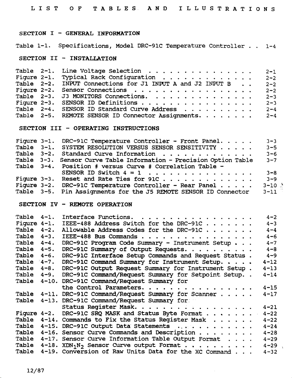
LIST
OF
TABLES AND ILLUSTRATIONS
SECTION
Table
SECTION
Table 2-1.
Figure 2-1.
Table
Figure
Table
Figure
Table 2-4,
Table 2-5.
SECTION
Figure
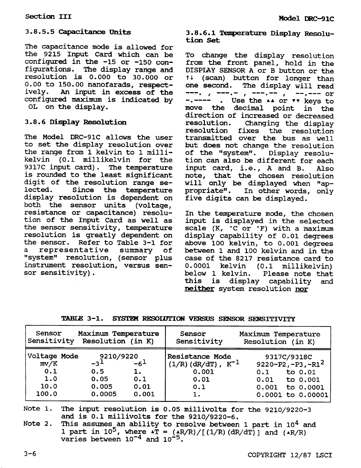
Table 3-1,
Table 3-2.
Table
Table
Figure
Figure
Table
1-1.
2-2,
2-2.
2-3.
2-3.
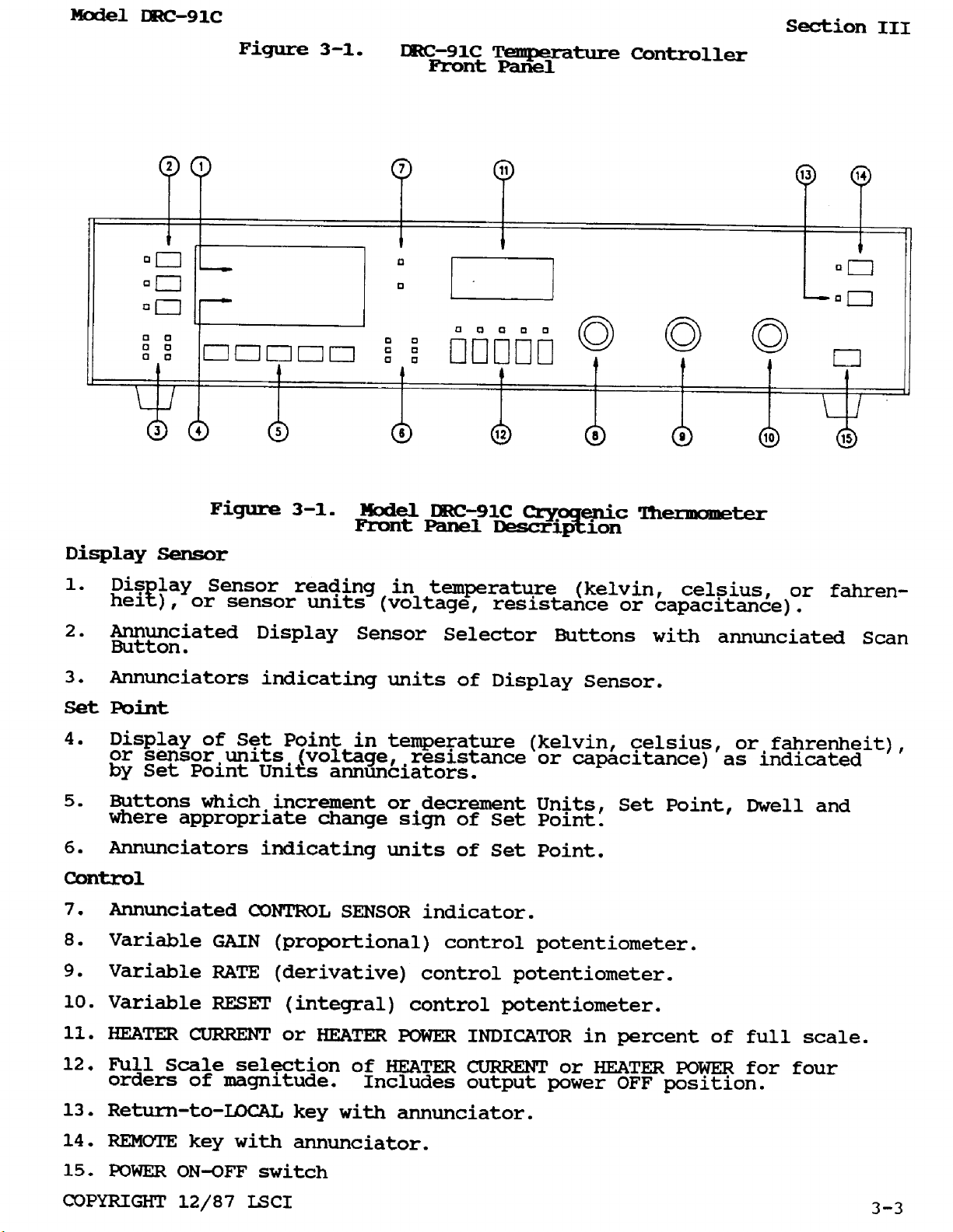
3-1.
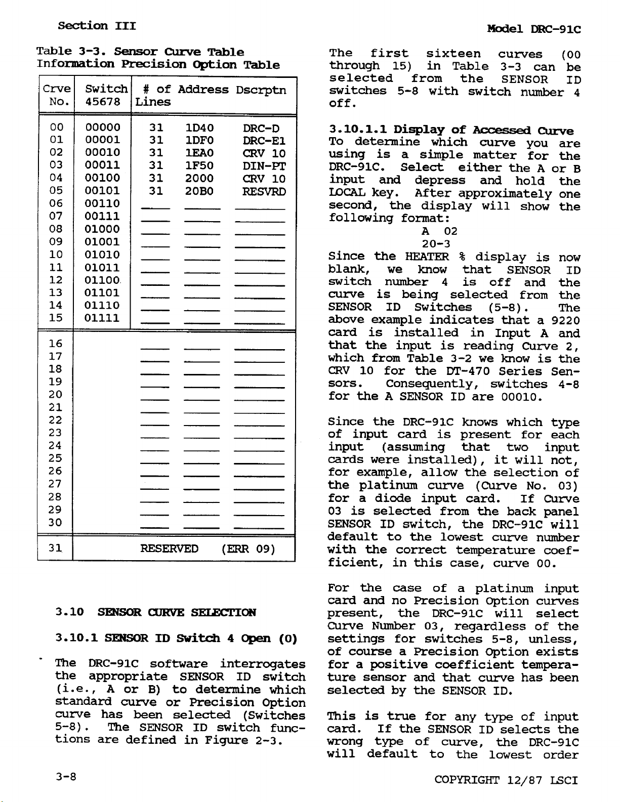
3-3.
3-4-
3-3.
3-2. DRC-91C
3-5.
I
-
GENERAL INFORMATION
Specifications,
II
-
INST-TION
Line
Typical
INPUT
Sensor
J3
SENSOR
SENSOR
REEMOTE
111
DRC-91C
SYSTEM
Standard
Sensor
Position
SENSOR
Reset
Pin
Voltage
Connections
Connections
MONITORS
ID
SENSOR
-
OPERATING
RESOLUTION
Curve
ID
and
Assignments
Model
Selection
Rack Configuration
DRC-91C Temperature
for
J1
.................
Connections.
Definitions
ID
Standard
ID
INSTRUCTIONS
Temperature
Curve
#
versus
Switch
Rate
Temperature
Information
Table
Ties
for
Connector
VERSUS
Information
Curve
4
................
Curve
Controller
#
=
1
for
91C
Controller - Rear
the
55
Controller
. .
...............
.............
INPUT A and
J2
INPUT
B
.
.
..............
Address
Assignments.
SENSOR SENSITIVITY
..........
.......
-
Front
Panel.
....
.....
.............
-
Precision
Correlation
Option
Table
Table
-
...............
.............
REMOTE
Panel
SENSOR
ID
.....
Connector
1-4
2-1
2-2
2-2
2-2
2-3
2-3
2-4
2-4
3-3
3-5
3-6
3-7
3-8
3
-9
3-10
3-11
SECTION
Table 4-1.
Figure
Table
Table
Table 4-4. DRC-91C
Table 4-5. DRC-9lC
Table
Table
Table 4-8. DRC-91C Output Request
Table
Table 4-10, DRC-91C Command/Request
Table 4-11, DRC-9lC Command/Request
Table 4-13, DRC-91C Command/Request
Figure
Table 4-14, Commands
Table 4-15. DRC-91C Output
Table 4-16,
Table 4-17.
Table 4-18.
Table
IV
-
REMOTE OPERATION
Interface
4-1. ZEEE-488
4-2,
4-3.
4-6.
4-7.
4-9.
4-2. DRC-91C
4-19.
Allowable Address
IEEE-488
DRC-91C
DRC-91C Comand
DRC-91C Command/Request
the
Status
Conversion
Control
Sensor
Sensor
XDN1N2
Functions.
Address
BUS
Program
Summary
Interface
Register
SRQ
to
Curve
Curve
Sensor
Commands
Parameters.
MASK
Fix
Commands
Information
Curve
of
Raw
................
Switch
Codes
................
Code Summary
of
Output Requests.
Setup
Summary
Mask.
and
the
Data
Units
................
Status
Status
Statements
and
output
for
for
the
the
DRC-91C
DRC-9lC
-
Instrument
.
. . . , .
.......
Setup
.
.........
Commands
for
Instrument
Sumnary
Summary
Summary
and
for
for
for
Request
Setup.
Instrument
Setpoint
Status
.
Setup
Setup.
. 4-12
...............
Summary
Sumnary
Register
Byte
for
for
Format
Scanner
.
Mask
.....
.
.
.
.
......
............
Description
Table Output
Data
Format
for
.
the
.
.
Format
.
.
XC
Command
.
. . .
.
. . .
.
.)
. .
.
.
.
.
4-2
. 4-3
4-4
4-6
.
.
.
.
4-7
4-8
4-9
4-13
4-14
4-15
4-17
4-21
. 4-22
4-22
4-24
.
4-28
4-29
.
4-29
. 4-32
.
12/87
Model
DRc-91c
Section
I
SECTION
I
GENERAL INFORMATION
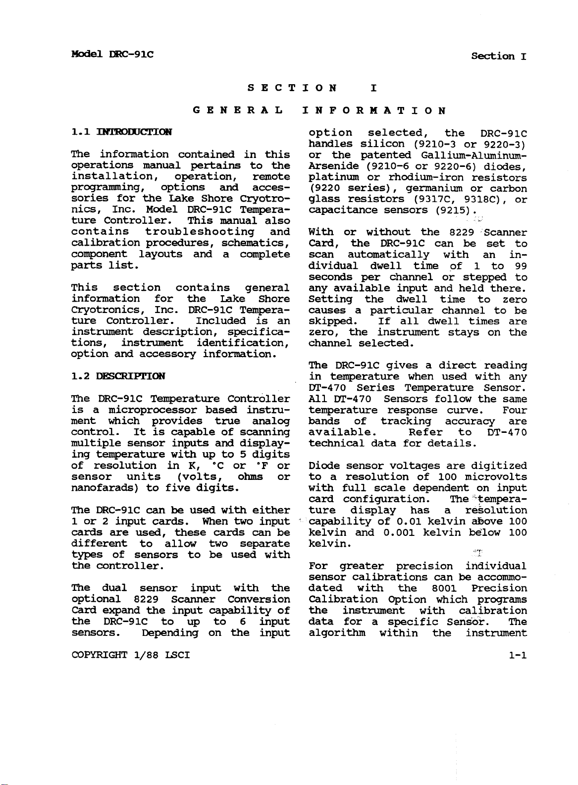
1.1
INTRODUCTION
option selected, the DRC-91C
handles silicon (9210-3 or
9220-3)
The information contained in this or the patented Gallium-Aluminumoperations manual pertains to the Arsenide
(9210-6
or
9220-6)
diodes,
installation, operation, remote platinum or rhodium-iron resistors
programming, options and acces- (9220 series), germanium or carbon
sories for the Lake Shore Cryotro- glass resistors (9317C, 9318c),
or
nics, Inc. Model DRC-91C Tempera- capacitance sensors (9215).
ture Controller. This manual also
contains troubleshooting and With or without the
calibration procedures, schematics, Card, the DRC-91C can
8229
be
Scanner
set to
component layouts and a complete scan automatically with an in-
1
to
parts list. dividual dwell time of
99
seconds per channel or stepped to
This section contains general any available input and held there.
information for the Lake Shore Setting the dwell time to zero
Cryotronics, Inc. DRC-91C Tempera- causes a particular channel to be
ture Controller. Included is an skipped. If all dwell times are
instrument description, specifica- zero, the instrument stays on the
tions, instrument identification, channel selected.
option and accessory information.
The DRC-91C gives a direct reading
1.2
DESCRIPTION
The DRC-91C Temperature Controller All
in temperature when used with any
DT-470
Series Temperature Sensor.
MI-470
Sensors follow the same
is a microprocessor based instru- temperature response curve. Four
ment which provides true analog bands
control. It
multiple sensor inputs
ing temperature with up to
of resolution
sensor units (volts,
is
capable
in
K,
of scanning available. Refer to DT-470
and
°C
or
display-
5
digits
°F or Diode sensor voltages are digitized
ohms
or to a resolution of 100 microvolts
technical data for details.
of
tracking accuracy are
nanofarads) to five digits. with full scale dependent on input
card configuration. The tempera-
The DRC-91C
1
or 2 input cards. When
cards are
different to allow
can
used,
be
used with either ture display has a resolution
two
input capability of
these cards can be kelvin and
two
separate kelvin.
0.01
0.001
kelvin above
kelvin below
100
100
types of sensors to be used with
the controller. For greater precision individual
sensor calibrations can
The dual sensor input with the dated with the
8001
be
accommo-
Precision
optional 8229 Scanner Conversion Calibration Option which programs
Card
the DRC-91C to up to
sensors.
expand the input capability of the instrument with calibration
6
input data for a specific Sensor. The
Depending
on the input algorithm within the instrument
COPYRIGHT
1/88
LSCI
1-1
Section
I
Model
DRC-91c
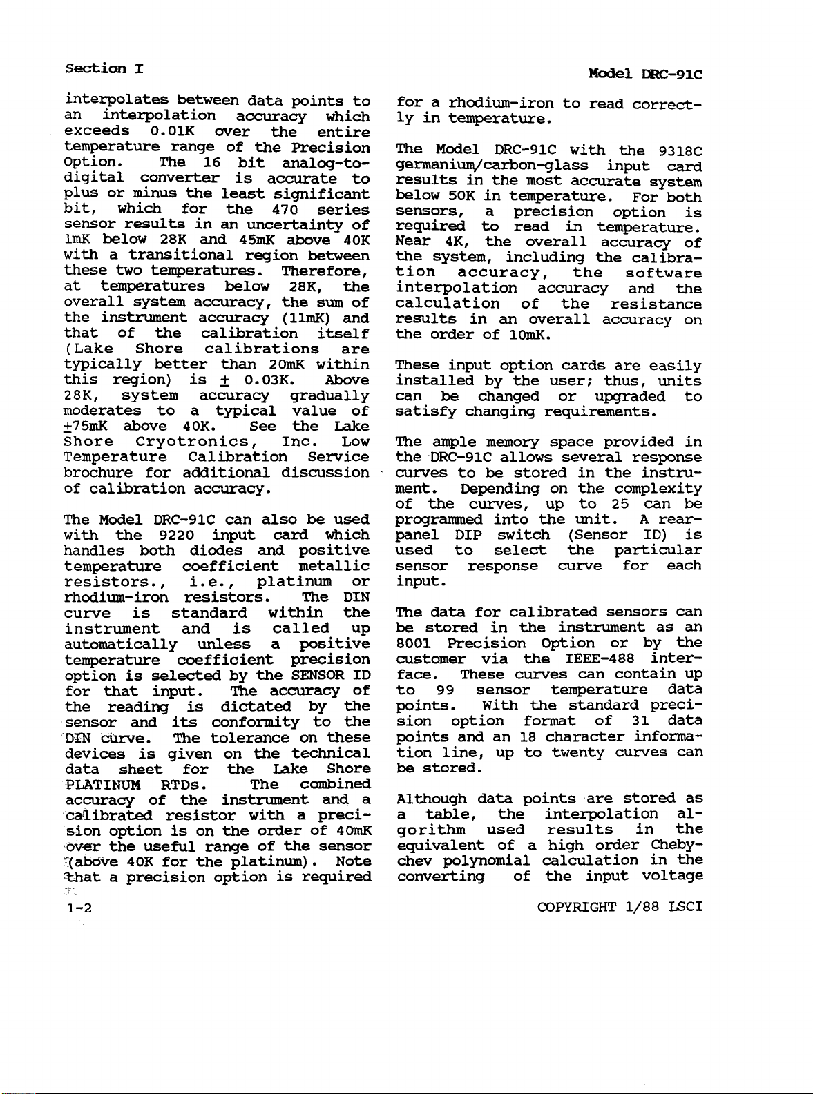
interpolates between data points to for a rhodium-iron to read correct-
an interpolation accuracy which ly in temperature.
exceeds
0.01K
over the entire
temperature range of the Precision The Model DRC-91C with the 9318C
option- The 16 bit analOg-tO- germanium/carbon-glass input card
digital converter is accurate to results
the
plus or minus
bit, which for the
least significant
470
series sensors, a precision option is
below
in
the most accurate system
50K
in temperature.
For both
sensor results in an uncertainty of required to read in temperature.
1mK
below
28K
and
45mK
above
40K
Near
4K,
the overall accuracy of
with a transitional region between the system, including the calibrathese
at temperatures below
overall system accuracy, the
the instrument accuracy (11mK)
that of the calibration itself the order of
two
temperatures. Therefore, tion accuracy, the software
28K,
the interpolation accuracy and the
sum
of calculation of the resistance
and
results in
an
overall accuracy on
10mK.
(Lake Shore calibrations are
typically better than
is
±
this region)
28K,
system accuracy gradually can be changed or upgraded
0.03K.
20mK
within These input option cards are easily
Above installed by the user: thus, units
to
moderates to a typical value of satisfy changing requirements.
-
+75mK above
Shore Cryotronics, Inc. Low The ample
40K.
See the Lake
memory
space provided in
Temperature Calibration Service the DRC-91C allows several response
brochure for additional discussion curves to be stored in the instru-
of
calibration accuracy. ment. Depending on the complexity
of the
The Model DRC-91C can also be used programmed into the unit.
with the
handles both diodes
9220
input
card
and
which panel DIP switch (Sensor ID) is
positive used to select the particular
curves,
up to 25 can be
A
rear-
temperature coefficient metallic sensor response curve for each
resistors.
,
i.
e.
,
platinum or input.
rhodium-iron resistors. The DIN
is
curve
instrument and
automatically unless a positive
standard within the The data for calibrated sensors can
is
called up be stored in the instrument as an
8001
Precision Option or by the
temperature coefficient precision customer via the IEEE-488 inter-
option is selected by the SENSOR ID face. These curves can contain up
for
that input. The accuracy of to
the reading
is
dictated by the points. With the standard preci-
sensor and its conformity to the sion option format of
DIN
curve. The tolerance
is
devices
given on the technical tion line, up to twenty curves can
on
these points and an
data sheet for the Lake Shore
be
stored.
99
sensor temperature data
18
character informa-
31
data
PLATINUM RTDs. The combined
accuracy of the instrument and a Although data points are stored as
calibrated resistor with a preci- a table, the interpolation alsion option is on the order of
over
‘(above
the useful range of the sensor equivalent of a high order Cheby-
40K
for the platinum). Note chev polynomial calculation in the
40mK
gorithm used results in the
that a precision option is required converting of the input voltage
1-2
COPYRIGHT
1/88
LSCI
Model
DRC-91c
Section
I
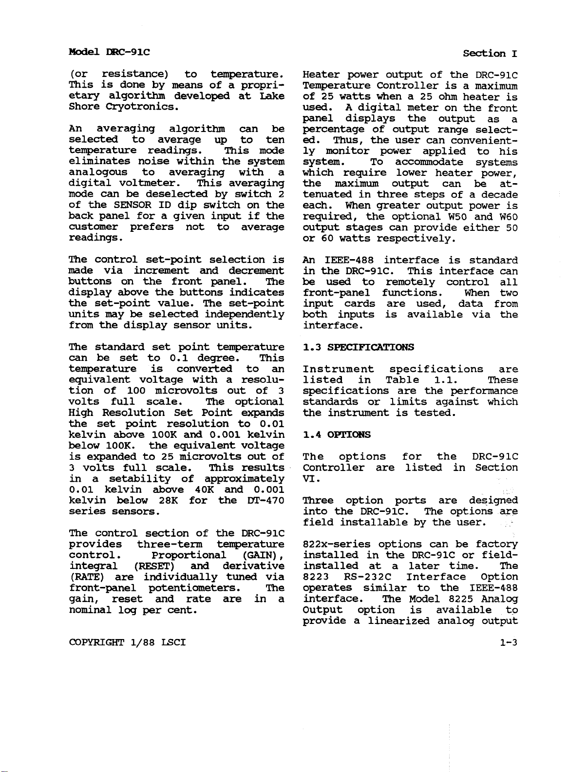
(or resistance) to temperature. Heater power output of the DRC-91c
This
etary algorithm developed at Lake of 25 watts when a 25
Shore Cryotronics. used.
An averaging algorithm can be percentage
is
done by means of a propri- Temperature Controller is a maximum
ohm
heater is
A
digital meter on the front
panel displays the output as
of
output range select-
a
selected to average up to ten ed. Thus, the user can convenienttemperature readings. This mode ly monitor power applied to his
eliminates noise within the system system.
To
accommodate systems
analogous to averaging with a which require lower heater power,
digital voltmeter. This averaging the
mode can be deselected by switch
2
tenuated in three steps of a decade
maximum
output can
be
at-
of the SENSOR ID dip switch on the each. When greater output power is
back panel for a given input if the required, the optional W50 and
customer prefers not to average output stages can provide either
readings. or
60
watts respectively.
W60
50
The control set-point selection is
An
IEEE-488 interface is standard
made via increment and decrement in the DRC-91C. This interface can
buttons on the front panel. The be used to remotely control
all
display above the buttons indicates front-panel functions. When two
the set-point value. The set-point input cards are used, data from
units may be selected independently both inputs is available via the
from the display sensor units.
The standard set point temperature
interface.
1.3
SPECIFICATIONS
can be set to 0.1 degree. This
temperature is converted to an Instrument specifications are
equivalent voltage with a resolu- listed in Table
of
tion
volts full
100 microvolts out of
scale.
The optional standards
High Resolution Set Point
expands
3
specifications are the performance
or
limits against which
the instrument
is
tested.
1.1.
These
the set point resolution to 0.01
kelvin
above
100K and 0.001 kelvin
1.4
OPTIONS
below 100K. the equivalent voltage
is expanded to 25 microvolts out of The options for the DRC-91C
3
volts full scale. This results Controller are listed in Section
in a setability of approximately
VI.
0.01 kelvin above 40K and 0.001
kelvin below 28K for the
DT-470
Three option
ports
are designed
series sensors. into the DRC-91C. The options are
field installable by the user.
The control section of the DRC-91C
provides three-term temperature 822x-series options can be factory
control. Proportional
integral
(RATE)
(RESET)
and
are individually tuned via 8223 RS-232C Interface Option
front-panel potentiometers. The operates similar to the
gain, reset and rate are
(GAIN),
installed in the DRC-91C
or
field-
derivative installed at a later time. The
IEEE-488
in
a interface. The Model 8225
Analog
nominal log per cent. Output option is available to
provide a linearized analog output
COPYRIGHT
1/88
LSCI 1-3
Section
of
I
10mV/K independent of the The Model
8229
Model DRC-91c
Scanner Option
display temperature units. If the provides four additional channels
display is in sensor units, the of
output for diodes is lV/V; for 100 The A input
ohm
platinum, 10mV/ohm; for 1000 additional inputs designated
ohm
platinum, 1mV/ohm; for rhodium- with the selection indicated on the
sensor
input to the
is
channel
“A”
A0
with the
input.
A1-A4
iron, 100m/ohm; and for capaci- display.
tance units, 100mV/nF and 10mV/nF.
Table 1.1.
Input Characteristics: temperature in
Specifications, Model
DRC-91C
Temperature
K,
Controller
°C, or
°F
shown
with annunciators.
Inputs:
8229
provides for four additional 0.001K below 100K,
channels of Sensor Input. Display
Two
Sensor Inputs. The
Scanner Conversion Option Resolution: Display resolution
(0.0001K
below
0.01K
10K
above 100K
for 9317C
is
sensor can be selected from front Resistance Sensor Input Card).
panel or interface, or display can Resolution can be user-limited to
be set to scan between sensor 1K, 0.1K or 0.01K. Same resolution
inputs. Dwell the per channel can considerations apply for °C,
be set independently from 0 (skip) Sensor Units. Changes made
to
99
seconds. Input character- front
panel
keys or over interface.
°F
and
by
istics are a function of Sensor
Input Option Installed. The DRC-
Temperature
Accuracy:
Dependent on
91C can accommodate two input Sensor Input Card and Sensor. See
options which allows the
and the
their
B
input to each be assigned
own
input
card.
concurrent use of different sensors
A
input Input Options available.
This allows
Temperature
Range:
Dependent of
Sensor Input Card and Sensor.
dependent on the application.
Sensors:
Temperature
Ordered Separately. DRC-
Control:
91C will handle all types of Set Point: Button increment
diodes; germanium, carbon glass, (either fast or
slow)
of set-point
carbon, etc. negative temperature in set-point units.
coefficient resistors, thermistors;
platinum, rhodium-iron, etc.
Set
Point
Resolution: Selection in
metallic resistors and ther- kelvin, Celsius, fahrenheit or
mocouples as well as capacitance Sensor Units. Temperature to 0.1
thermometers with proper choice of in corresponding units; in Sensor
input option cards. See the Lake Units, 0.1mV in voltage, 0.01
ohms
Shore Cryotronics, Inc. Sensor but limited to five digits in
catalog for details on the above resistance and
15
Sensors. of
nanofarads
0.001
nanofarads out
(0.01
nanofarads
out of 150 nanofarads for second
Display
Readout:
scale) in capacitance. May also be
set over the interface.
Display: 5-digit
LED
Display of
Sensor reading in Sensor Units
(Volts,
Ohms
or Nanofarads) or
1-4
COPYRIGHT
1/88 LSCI
Model
DRC-91c
Section
I
Typical Controllability: Dependent is 0.457771 for
on Sensor,
resultant Sensor “gain”,
sensitivity. Typically better than (-P2, -P3,
its
temperature and the For 9220 Option positive tempera-
i.
e.
,
ture coefficient configurations
-R1),
0.001K in a properly designed voltage output times
system below 30K and
10mK
above 30K outputs for 9210-6 and
-6
configurations.
buffer is sensor
-10.
Buffered
9220-6
are
using a Diode Sensor. But, for multiplied by 0.457771. For 9215,
example, a thermistor, due to its signal is proportional to capaci-
large sensitivity,
may
result in
a
tance value: for 9317C or 9318C,
controllability approaching 0.5mK monitor not of use.
above 200K over a narrow tempera-
ture range in certain systems and a
germanium below
0.
1mK
in another system. non-Lagrangian calculations.
10K
may control to than 1 second to rated accuracy for
Response
time
(electronics):
Less
Lagrangian curves result in update
Control
(GAIN),
derivative
Modes:
integral
(RATE).
panel knobs or with interface.
Heater
(1A,
output:
25V) standard. Four output control of set-point, gain, rate,
Proportional times between one and two seconds.
(RESET)
and Three readings
on
channel change or
Set via front- range change to reach rated
accuracy.
Up to 25 watts
IEEE-488
Interface: Allows remote
ranges can be selected either from reset, units and heater power
front-panel or interface and range. Provides output of display
provide approximate decade step
reductions of
Optional
maximum
50
or
power output. front panel functions (except power
60
watt outputs on/off and Display Sensor Selecavailable. Rear panel maximum tion). Allows input
current limit for
MAX
scale. for calibrated sensors.
in
units chosen, units and all
of
curve data
Heater
continuously shows heater current 102mm high
or power output as a percentage of 4in.
range with a resolution of
control
output
Sensor:
Monitor:
LED display Dimensions, Weight:
x
x
13in.) Style
1%.
Either Sensor
package. Net weight 8kg (17 1b.)
Rwer:
90-110, 105-125, or 210-250
330mm
432mm
wide x
deep (17in. x
L,
full-rack
.
Input (designated from rear panel). VAC (selected via rear panel with
General:
Sensor
Voltage
Monitor:
instrument off), 50 or
watts.
For 9210 Accessories Supplied: Mating
60
Hz,
75
and 9220 diode Option configura- connector for sensor/monitor
tions (-3,
-6),
buffered output of connector, instruction manual.
diode sensor voltage. Multiplier
COPYRIGHT
1/88
LSCI
1-5
Model
DRC-91c
section
II
SECTION
II
INSTALLATION
2.1
INTRODUCTION
Inc. of such filings. In case
parts shortages, advise LSCI
of
im-
This Section contains information mediately. LSCI can not be responand instructions pertaining to sible for any missing parts unless
instrument set-up. Included are notified within
inspection procedures, power and ment. The standard Lake Shore
grounding requirements, environ- Cryotronics Warranty
mental information, bench and rack
the first page of this manual.
60
days of
is
ship-
given
on
mounting instructions, a description of interface connections, and
2.3
PREPARATION
FOR
USE
repackaging instructions.
ts
2.2
INITIAL
INSPECTION
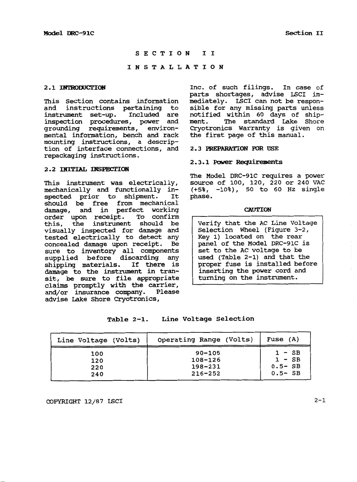
2.3.1
Power
Requiremen
The Model DRC-91C requires a power
This instrument was electrically, source of
mechanically and functionally in-
(+5%,
100,
-10%),
120, 220
50
to
60
or
Hz
240
VAC
single
spected prior to shipment. It phase.
should be free from mechanical
damage, and in perfect working CAUTION
order upon receipt. To confirm
this, the instrument should be
visually inspected for damage and
tested electrically to detect any
concealed damage upon receipt.
Be
sure to inventory all components
supplied before discarding any
If
shipping materials.
there is
damage to the instrument in tran-
sit,
be
sure to file appropriate
Verify that the AC Line Voltage
Selection Wheel (Figure
Key
1)
located on the rear
3-2,
panel of the Model DRC-91C is
to
set
used (Table
the AC voltage to be
2-1)
and that the
proper fuse is installed before
inserting the power cord and
turning on the instrument.
claims promptly with the carrier,
and/or insurance company. Please
advise Lake Shore Cryotronics,
COPYRIGHT
12/87
Table
LSCI
2-1.
Line Voltage Selection
2-1
section
II
Model
DRC-91C
Figure
2.3.2
A
for
Power
Cord
three-prong detachable power cord The
120
VAC
operation which mates pin input connectors for diode and
2-1.
Typical
Rack
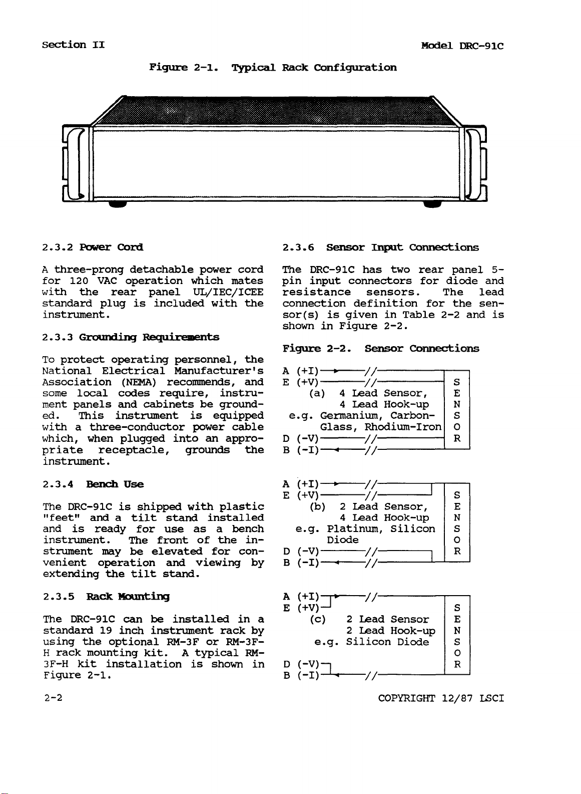
2.3.6
Configuration
Sensor
DRC-91C
Input
has two rear panel
Connections
5-
with the rear panel UL/IEC/ICEE resistance sensors. The lead
standard plug is included with the connection definition for the sen-
instrument. sor(s) is given in Table
2.3.3
To
Grounding
Requirements
protect operating personnel, the
shown in Figure
Figure
2-2.
2-2.
Sensor
Connections
2-2
and is
National Electrical Manufacturer's
Association
(NEMA)
recommends, and
some local codes require, instrument panels and cabinets be grounded. This instrument is equipped
with a three-conductor power cable
which, when plugged into
an
appro-
priate receptacle, grounds the
instrument.
2.3.4
The
Bench
DRC-91C
Use
is shipped with plastic
“feet” and a tilt stand installed
and is ready for use as a bench
instrument. The front of the in-
strument may
be
elevated for con-
venient operation and viewing by
extending the tilt stand.
2.3.5
The
standard
Rack Mounting
DRC-91C
19
can
inch
be
installed in a
instrument rack by
using the optional RM-3F or RM-3F-
H
rack mounting kit.
3F-H
Figure
2-2
kit installation is shown in
2-1.
A
typical
RM-
COPYRIGHT
12/87
LSCI
Model
DRC-91C
Section
II
Connections for capacitance sensors is Phosphor Bronze with a Fomvar
and thermocouples are made through insulation and Butryral bonding
alternate connectors. Refer to the between the four leads. Color codappropriate input card section for ing is red, green, clear and blue
sensor connections.
on the four leads which makes it
extremely easy to determine one
The four lead connection (a) is wire from another.
required for a four lead sensor.
The use
of
a four wire connection
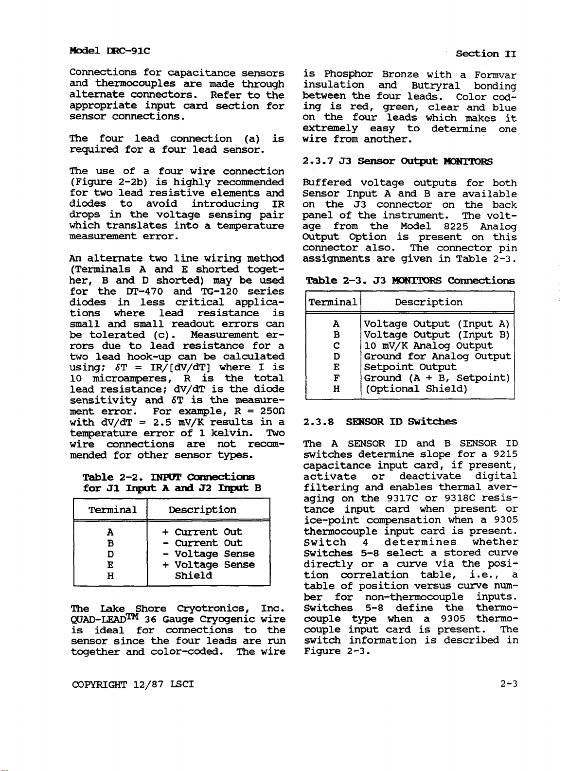
2.3.7
J3
Sensor
Output
MONITORS
(Figure 2-2b) is highly recommended Buffered voltage outputs for both
for two lead resistive elements and Sensor Input
diodes to avoid introducing
IR
on the J3 connector on the back
A
and B are available
drops in the voltage sensing pair panel of the instrument. The volt-
which translates into a temperature age from the Model
measurement error. Output Option
is
connector also. The connector
An
alternate two line wiring method assignments are given in Table
(Terminals
her, B and
A
and
E
shorted toget-
D
shorted) may be used
Table
2-3. 53
MONITORS
8225
Analog
present on this
pin
2-3.
Connections
for the MI-470 and TG-120 series
diodes in less critical applications where lead resistance is
small
be
and
small readout errors can
tolerated (c) . Measurement errors due to lead resistance for a
two lead hook-up can
=
using; §T
IR/[dV/dT] where I is
10 microamperes,
R
be
calculated
is
the total
lead resistance; dV/dT is the diode
is
sensitivity and §T
ment error. For example, R
=
with dV/dT
2.5 mV/K results in a
temperature error
wire connections are not recom- The
mended for other sensor types.
Table
for
J1
2-2.
Input
INPUT
A
and
the measure-
of
1 kelvin.
connections
J2
Input
=
250
B
Two
2.3.8
switches determine slope
capacitance input card,
SENSOR
A
SENSOR
ID
Switches
ID
and
B
SENSOR
for
if
present,
ID
a 9215
activate or deactivate digital
filtering and enables thermal averaging on the 9317C or 9318C resistance input card when present or
ice-point compensation when a
9305
thermocouple input card is present.
Switch
Switches
4
determines whether
5-8
select a stored curve
directly or a curve via the psition correlation table, i.e.,
a
table of position versus curve number for non-thermocouple inputs.
The Lake Shore Cryotronics, Inc. Switches 5-8 define the thermo-
QUAD-LEAD™
36
Gauge cryogenic wire couple type when a 9305 thermois ideal for connections to the couple input card is present. The
sensor since the four leads are
together and color-coded. The wire Figure
run
switch information is described
2-3.
in
COPYRIGHT
12/87
LSCI
2-3
section
II
Model
DRC-91c
Table
the
2-4
address
indicates the position of
switches to
select
standard curves stored within
instrument. Information on
cision Option
Appendix
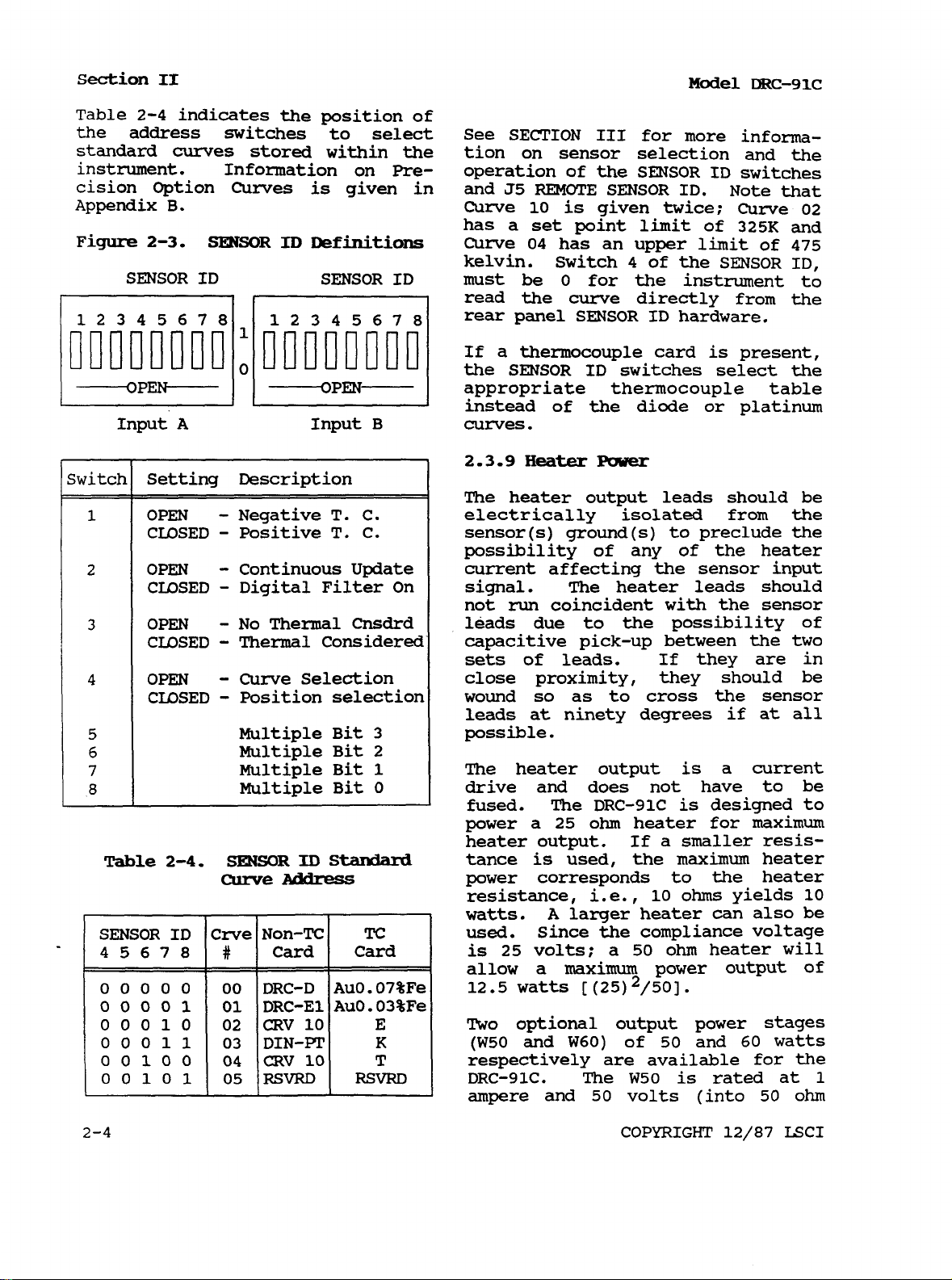
Figure
B.
2-3.
Curves
SENSOR
is
given in and
ID
Definitions
the
Pre-
See
SECTION
tion
on
operation of
J5
REMOTE
Curve
has
Curve
kelvin.
must
read
rear
If
the
10
a
set
04
be
the
panel
a thermocouple
SENSOR
III
for more infoma-
sensor selection and
the
SENSOR
SENSOR
is
given
point
limit
has an upper
Switch
0
4
Or
for the instrument to
ID
ID.
twice;
of 325K
limit
me
SENSOR
switches
Note that
Curve
curve directly from
SENSOR
ID
ID
hardware.
card
switches
is
select
present,
the
02
and
of 475
ID,
the
the
appropriate thermocouple table
instead
the
diode
or platinum
of
curves.
2.3.9
The
electrically isolated
sensor(s) ground(s) to preclude
Heater
heater
Power
output leads should
from
be
the
the
possibility of any of the heater
current affecting
the
sensor input
signal. The heater leads should
not
run
coincident
leads due to
capacitive pick-up between
sets
of leads.
close proximity, they should
wound
leads
so
as to cross
at
ninety
the
degrees
with
the
sensor
possibility of
the
If
they are
the
sensor
if at all
two
in
be
possible.
Table
2-4.
SENSOR
curve
ID
stardard
Address
The heater output
is
a current
drive and does not have to
fused. The
power a
heater output.
tance
is
power corresponds to
resistance,
watts.
used.
is
allow
12.5
TWO
(W50
Since the compliance voltage
25
volts;
a
watts
optional output power stages
and
respectively
DRC-91C.
ampere
and
DRC-91C
25
ohm
used, the
i.e.,
A
larger
a
maxim
[
(25) 2/50].
W60)
are
The
50
is
designed
heater
If
a
for maximum
smaller
maximum
the
10
ohms
heater can
50
ohm
heater
power output
of
50
and
available for
W50
is
rated at
volts (into
COPYRIGHT
resisheater
heater
yields
also
60
50
12/87
watts
be
to
10
be
will
of
the
1
ohm
LSCI
Model
DRC-91c
Section
11
load) while the
amperes at approximately
25
(into
A
50
ohm
ohm,
50
W60
is rated at 1.5
43
volts
load).
watt (1/4" dia. x 1"
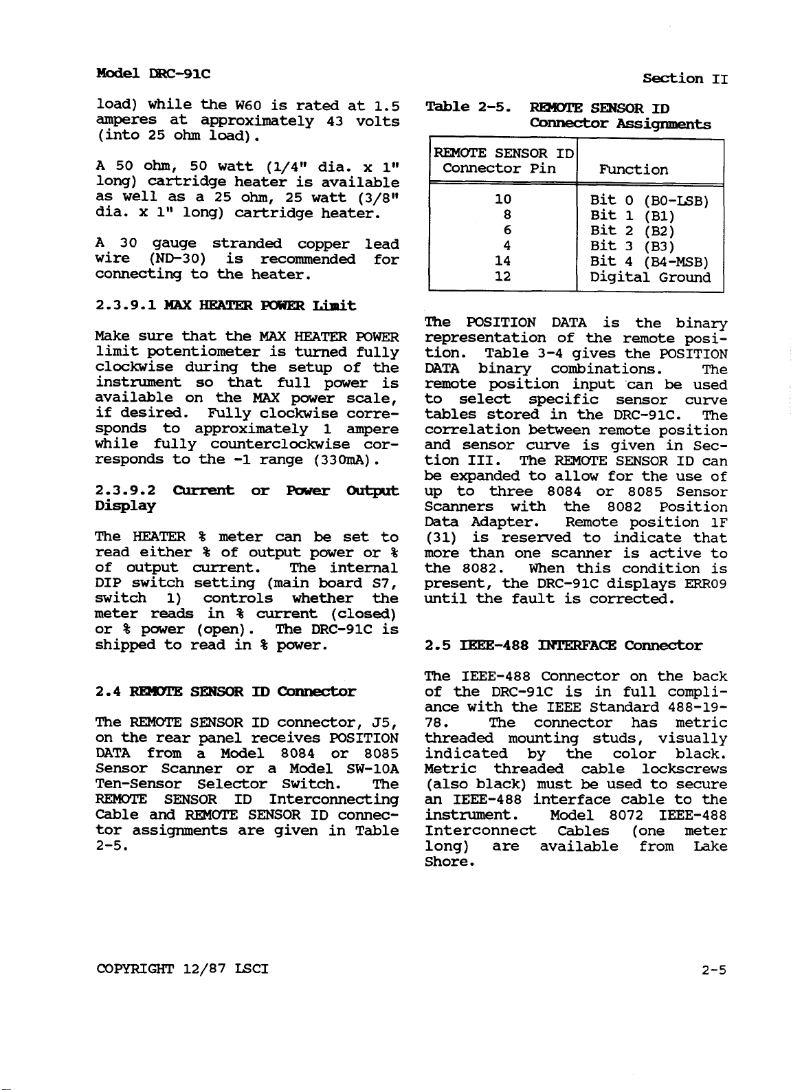
Table
2-5.
REMOTE
connector
SENSOR
ID
Assignments,
long) cartridge heater is available
as well as a
dia.
A
wire
x
1"
long) cartridge heater.
30
gauge stranded copper lead
(ND-30)
ohm,
is recommended for
25
watt
(3/8”
25
connecting to the heater.
2.3.9.1
MAX
HEATER
POWER
Limit
The POSITION DATA is the binary
Make sure that the
limit potentiometer is turned fully
clockwise during the setup of the DATA binary combinations.
instrument
so
available on the
if
desired. Fully clockwise corre- tables stored in the DRC-91C.
MAX
HEATER
POWER
that full power
MAX
power scale, to select specific sensor
is
representation of the remote posi-
3-4
tion. Table
gives the POSITION
The
remote position input can be used
curve
The
sponds to approximately 1 ampere correlation between remote position
while fully counterclockwise cor- and sensor curve is given in Sec-
responds to the -1 range
2.3.9.2
Current
or
(330mA)
Power
Display
The
HEATER
read either
%
meter can
%
of output power or
be
of output current. The internal the
DIP switch setting (main board
.
Output
tion III. The
be
expanded to allow for the use
up to three
Scanners with the
REMOTE
8084
SENSOR ID can
or
8085
8082
Sensor
Position
Data Adapter. Remote position
of
1F
set to (31) is reserved to indicate that
%
S7,
more than one scanner is active
8082.
When this condition is
present, the DRC-91C displays
to
ERR09
switch 1) controls whether the until the fault is corrected.
meter reads
or
%
power
shipped to read in
in
%
(open).
current (closed)
The DRC-91C is
%
power. 2.5 IEEE-488
INTERFACE
Connector
The
2.4
The
REMOTE
REMOTE
SENSOR
ID
Connector
SENSOR ID connector,
of the DRC-91C is in full compliance with the IEEE Standard
J5, 78.
IEEE-488
The connector has metric
Connector on the back
488-19-
on the rear panel receives POSITION threaded mounting studs, visually
DATA from a Model
8084
or
8085
indicated by the color black.
Sensor Scanner or a Model SW-10A Metric threaded cable lockscrews
Ten-Sensor Selector Switch. The (also black) must be used to secure
REMOTE
Cable
SENSOR
and
ID Interconnecting an
REMOTE
SENSOR
IEEE-488
ID
connec- inStrUment. Model
interface cable to the
8072 IEEE-488
tor assignments are given in Table Interconnect Cables (one meter
2-5.
long) are available from Lake
Shore.
COPYRIGHT
12/87
LSCI
2-5
Section
2.6
2.6.1
The
Section
II
OPTIONS
The
RS-232C
VI
DRC-91C
should be operated at an
ambient temperature range of
8223 RS-232C
Interface.
5°C.
The unit may be operated
option is described in within the range
of this manual including less accuracy.
of
Model
15-35°c
DRC-91c
23°c
with
±
connections.
2
.
7.2
Hummidity/Altitude
2.6.2
is
manual.
The
described in Section
8225
Linear
Analog
output
VI
of this The
DRC-91C
is
for laboratory use
and no humidity or altitude speci-
fications have been determined for
2.6.3
is described in Section
Section
2.6.4
expands the set point resolution to If the Model
0.01
kelvin below
voltage
volts out
This results in
approximately
and
DT-470 series semors.
The
VI
The
8229
High
Scanner
of this manual.
Resolution
kelvin above
100K.
is
expanded to
of
3
0.01
0.001
kelvin below
Input
100K
Option this unit.
III
and
2.8
set
point
and
0.001
operating incorrectly, refer to the
REPACKAGING
DRC-91C
FOR
SHIPMENT
appears
to
The equivalent Technical Service Guide for
25
micro- troubleshooting advice. If these
volts full scale. tests indicate that there is
a
setability of fault with the instrument, contact
kelvin above 40K
28K
for the for a Return
LSCI
(RGA)
or a factory representative
Goods
Authorization
number before returning the
be
a
instrument to our service depart-
2.6.5
tom
calibration
8001
precision
option.
Cus-
programing of specific Sensor
curve(s)
at factory.
ment.
When
returning an instrument for
Provides highest degree of readout service, the following information
accuracy. must
can attempt
2.6.6
tions will deliver
respectively. The
1
load with the
The
ampere
and
W50
50
and
W60
Output
50
or
60
W50
is rated at
volts into a
W60
rated at
Op
watts
50
ohm
1.5
1.
2.
3.
amperes at approximately 43 volts 4. Description
into a
25
ohm
load. These are
5.
be
provided before Lake Shore
any
repair.
Instrument Model and Serial
#s
User's Name, Company, Address,
and Phone Number
Malfunction Symptoms
of
system
Returned
Goods
Authorization
#
factory options only.
If the original carton is avail-
2.7
ENVIRONMENTAL
REQUIREMENTS
able, repack the instrument
in
a
plastic bag, place it in the carton
WARNING using original spacers to protect
protruding controls. Seal the
To
prevent electrical fire
or
shock hazards, do not expose
the instrument to rain or excess
carton with strong paper or nylon
tape. Affix shipping labels
and
“FRAGILE” warnings.
moisture.
If the original carton is not
available, pack the instrument
2.7.1
Operating
Temperature
similar to the above procedure,
being careful to use spacers
or
In order to meet and maintain the suitable packing material on all
specifications in Table
1-1,
the sides
Of
the instrument.
2-6
COPYRIGHT
12/87
LSCI
 Loading...