

Lakeshore DRC-84C User Manual
User’s Manual
Model
DRC-84C
Digital Cryogenic
ThermometerlControlIer
Obsolete Notice:
This manual describes an obsolete Lake Shore product. This manual is a copy from our
archives and may not exactly match your instrument. Lake Shore assumes no responsibility for
this manual matching your exact hardware revision or operational procedures. Lake Shore is
not responsible for any repairs made to the instrument based on information from this manual.
Lake Shore Cryotronics, Inc.
575
McCorkle Blvd.
Westerville, Ohio 43082-8888 USA
E-Mail Addresses:
sales@lakeshore.com
service@lakeshore.com
Visit Our Website:
www.Iakeshore.com
Fax: (61 4) 891-1392
Telephone: (614) 891-2243
Methods and apparatus disclosed and described herein have been developed solely on company funds of Lake Shore Cryotronics, Inc.
No
government or other contractual support or relationship whatsoever has existed which in any way affects or mitigates proprietary
rights of Lake Shore Cryotronics, Inc. in these developments. Methods and apparatus disclosed herein may be subject
existing or applied for. Lake Shore Cryotronics, Inc. reserves the right
modifications,
consequential damages in connection with furnishing, performance, or use
Obsolete
or
products at any time without notice. Lake Shore shall not be liable for errors contained herein or for incidental or
Manual
to
add, improve, modify, or withdraw functions, design
of
this material.
to
U.S.
April
Patents
1982
Table
of
Contents
Section
I.
General Information
1.1
1.2 Description
1.3 Major Assemblies Supplied
1.4 Ordering of Replacement or Additional Sensors
II.
Ins tallation
2.1 Introduction
2.2
2.3 Power Requirements
2.4 Grounding Requirements
2.5 Installation
2.6 Repackaging for Shipment
III.
Operating Instructions
3.1
3.2 Controls, Indicators, Connectors
3.3 Temperature Readout
3.4 Analog Control
3.5 Analog Output of Temperature
3.6 Standard DT-500-DRC and DT-500CU-DRC-36 Curves
3.7
3.8
3.9
3.9.1 General
3.9.2 Specific Operation
3.9.3 Sample Programming
3.10
3.11
3.12 Rack Mounting the DRC-84C
3.13 Error Conditions
Introduction
Initial Inspection
Introduction
The 10-Sensor Selector Switch
Remote Parallel
IEEE
Installation of
Installation
Interface Option
IEEE
BCD
Input/Output Option
Specifications and Operation
of
the DRC8-IEEE Interface
DRC
of
DRC
BCD/L-A
IEEE
Option Board
Option Board
Page
1
1
3
3
5
5
5
5
5
6
9
9
12
12
13
13
13
14
26
26
27
32
34
35
36
36
-ii-
IV.
Theory
4.1 Introduction
4.2 General Description
4.3 Detailed Description
4.3.1 Power Supplies
4.3.2
4.3.3
4.3.4 Software
4.3.5
4.3.6 Digital Display Board
of
Operation
Precision Current Sources and Input Switching
A/D
Converter and Microprocessor Hardware
Analog Control and Set Point
37
37
39
39
40
40
41
44
45
Table
of
Contents (cont'd.)
Section
V.
VI.
Calibration and Troubleshooting
5.1
5.2
5.3 General Remarks
5.4 Instrument Calibration
5.4.1 Current Sources
5.4.2
5.4.3
5.4.4 Output Buffer
5.4.5
5.5
Replaceable Parts
6.1
6.2 DRC-84C
Introduction
Test
Equipment
A/D
Converter
D/A
Converter
DRC
L/A
Instrument
Main
Board Components
Option
Tests
List
BCD-L/A
(if
and
present)
IEEE
Components
List
Page
47
47
47
47
47
48
48
51
51
55
55
63
-iii-

Table of Illustrations
Reference
Figure
Figure 2.1
Table 3.1
Figure
Figure 3.2
Table 3.2
Table 3.3
Figure
Table 3.4
Figure 3.4
Table 3.5
Table 3.6
Table 3.7
Figure 4.1
Figure 4.2
Table 5.1
Table 5.2
Table 5.3
Table 5.4
1.1
3.1
3.3
Description
Model DRC-84C Digital Cryogenic
Thermometer/Controller
Sensor, Cable, and Monitor Connections
Entry Number Correlation
DRC-84C Front Panel
DRC-84C Back Panel
BCD
Relative Gain for
Reset
DRC-84C-IEEE Panel Layout
DT-500-DRC Voltage-Temperature Characteristic
Model DRC-84C showing Rack Mount
SW-1OA Connector
BCD
DIN
DRC-84C Block Diagram
Software Flow Diagram
Decimal-hex Table
Data
DRC-84C Troubleshooting Notes
DRC-84C Troubleshooting Notes
Time
Constants for
Detail
Temperature Output - Model DRC-Series
Remote
Standard Curve for Platinum Sensors
1/0
for Standard Curves (D
Option
BCD
Option
&
E)
Kit
Page
7
9
11
11
15
16
28
17
35
20
21
22
38
43
49
49
52
53
Figure 6.1
Figure 6.2
Figure 6.3
Figure 6.4
Figure 6.5
Figure 6.6
Figure 6.7
Figure 6.8
Figure 6.9
Figure
Figure 6.11
6.10
DRC-84C Power Supply
DRC-84C Current Source, Input Connections,
Switching
DRC-84C
DRC-84C Analog Output Section
DRC-84C Component Layout
DRC-84C Display Board
DRC-84C Display Board Component Layout
DRC-84C
DRC-84C
DRC-84C
DRC-84C
Microprocessor Section
BCD/L-A
BCD/L-A
IEEE
IEEE
Option
Option Component Layout
Option
Option Component Layout
67
69
71
73
75
77
77
79
79
81
81
-iv-

Specifications, DRC-84C Temperature Controller
Input: General:
Temperature Range:
diode DRC Sensor
30
to
800K with platinum sensor. Silicon diodes cannot Additional outputs listed below as options.
be exposed
Sensors (order separately):
DT-500CU-DRC-36 or any calibrated DT-500 Series package. Net weight 8.4 kg (18.5 Ibs).
Diode (with DRC-Precision Option). See below for
proper response curve. Platinum RTD: PT-101. PT-102, 75 watts,
PT-103'
See response curve details below.
Sensor Input:
platinum RTD). Front-panel switch selects either section.
Each section accommodates two sensors with 4-terminal
input for each sensor. Front-panel switches enable
independent selection of either sensor within each patible. Allows remote control of set-point, gain,
section as display and/or control sensor. Display/control reset, and provides BCD
sensors cannot be mixed between silicon and platinum and Sensor selected (either from front-panel or optional
sections. SW-10A)
Sensor Excitation:
for each sensor in silicon-diode section,
(±0.005%) for each sensor in platinum RTD section. temperature in Kelvin and Sensor selected (either from
Sensor Response Curves:
tic US units require Sensor Curve "D". Export units
require Sensor Curve
change, refer
ing Sensors. Curves
on special request. See also DRC-Precision Option. except for use when unit is also equipped with
Platinum RTD Section: Standard response curve is
based on 0.1% interchangeability at 0°C and temperature coefficient (0-100°C)
to
Lake Shore PT-100 Technical Data for details.
Special calibrations are available and may be incorporated into the 84C via the DRC-Precision Option.
Input Resistance:
mum Sensor Power Dissipation: Silicon-diode: 25µW
at 4.2K. Platinum: 25µW below 80K increasing
at 273K.
Temperature Readout:
Display:
directly in Kelvin or Celsius as selected by front-panel
switch. Display Sensor can be selected independent of
Control Sensor within each section.
Resolution:
resolution to 0.01 K for temperatures below 30K and
0.05K for 30-100K (no increase in accuracy).
Accuracy (20-25°C ambient):
4K and 77K. ±1.0K at 300K with standard sensor. calibration range. Any DT-500 Series Silicon Diode
Accuracy with Lake Shore calibrated Sensor and DRC- Sensor or PT-100 Series Platinum RTD can be utilized.
Precision ±0.1 K or better depending on calibration Requires that an appropriate calibration be purchased
range. Platinum RTD: Conforms
±0.1K. See Lake Shore PT-100 Technical Data for 1-10 on SW-10A)
details. Calibrated Sensor and DRC-Precision improves within PROM.
accuracy to ±0.01K depending on range. First calibration stored
Temperature Control: Model DT-500-DRC.
Set-Point:
Kelvin,
Panel switch. Remotely settable in Kelvin with BCD
or IEEE-488 Option. Sensor (8mm diameter
Set-Point Resolution:
Typical Controllability:
designed system. long).
Control Mode:
Set via front panel or remotely with BCD or IEEE-488 long).
option.
Heater Output:
LO: 0-10 watts nominal (1A max or 12V rnax). Isolated
Output. 25-ohm heater is recommended.
Control Sensor:
independent of Display Sensor within either section.
to
Or
any
4 digit, 1.1 cm (0.43") LED shows temperature
0.1K or 0.1°C. "Scale Expand" increases 3½" rack
Digital thumbwheel selection directly in (1.5mm diameter X 4.1mm long). Specify response
(+)
Celsius, or
1.4
to
(to
temperatures above their useful
Other
Two section input (silicon-diode and
330K with standard silicon
380K with other silicon Sensors). voltage (silicon) and5X Display Sensorvoltage (platinum).
range.
Silicon Diode: DT-500-DRC.
100-ohm, 0.00385/°c
Sensor'
Monltor Output:
Dimensions,
330mm deep
power:
90-110, 105-125, or 210-250VAC.
Accessories Supplied:
inputs and monitors, instruction manual.
Options and Accessories Available:
Model DRC8-BCD.
Buffered output of 1X Display Sensor
Weight:
432mm wide x 102mm high x
(17 in
x
4 in x 13 in). Style L. full-rack
Mating connectors for sensor
Parallel BCD interface, TTL com-
output
.
Current source. 10, microamperes
Silicon Diode Section: Domes-
"E".
to
manual for proper curve when reorder- 10mV/K at<10 ohm output resistance.
Greater than 1000 megohms. Maxi-
Proportional (gain) and integral (reset).
HI:
Selected by front-panel pushbutton
Sensor curves subject
to
match existing Sensors available
Silicon-diode: ±0.5K at specified accuracy
to
(-)
Celsius as determined by front-
0.1K or 0.1°C.
0.1K or better in a properly
0-25 watts (1A max. 25V max). long).
0.5
milliampere of set-point, gain, reset and provides digital output of
of
O.O0385/"C. Refer
to
100µW
DIN 43760 tolerances for the Sensor. Specify Sensor input position (A or B or
Model DRC8-IEEE.
front-panel or optional SW-10A)
Model DRC8-L/A.
to
temperature for use with recorders, or other readouts.
Model KT-LA.
488 interface. Allows remote control
Analog output proportional
Analog output identical
BCD,
Model KT-BCD.
DRC8-BCD
with
DRC8-L/A,
Model SW-10A.
DRC Thermometer or Controller. Pushbutton selection
of
any
one
position. Sensor selected
interfaces.
x
330mm deep (8% in x 4 in x 13 in). Style L half-
rack package.
Model RM-3F.
L
full-rack instrument package in standard 3%" rack
space
Model
RM-3H.
either one of two Style L half-rack unit(s) in standard
DRC-Precision Option:
only-memory for DRC instruments which improves
space,
Parallel
except
10-Sensor Selector Switch for use with
of
up
to
Dimensions: 216mm
Rack ears with handles
Rack
to
BCD
for
use
when
10
sensors,
is
mounting
Custom-programmed
to
±0.1K or better over a given
assure proper location
.
Subsequent Calibrations stored in same PROM.
Silicon Diode Temperature Sensor
curve
.
Model DT-500CU-DRC-36.
hole). Specify response curve
Model PT-101.
Model
Model PT-103.
Platinum RTD (3.lrnm diameter x 30.5
PT-102.
PIatinurn
Platinum RTD
Specifications subject
Silicon Diode Temperature
x
3.3mm thick with mounting
RTD
(2.0mm diameter x 20.3rnrn
(1.8mm
50
or 60Hz.
of temperature in Kelvin
.
to
Kelvin
to
DRC8-L/A
DRC8-
interface
unit
Connects
also identified via digital
wide
hardware
.
to
change.
identical
is
also
equipped
to
Sensor
"B"
x
102mm
high
to
mount style
to
mount
read-
of
calibration
rnrn
diameter x 12.1mm
to
-V-
-vi-
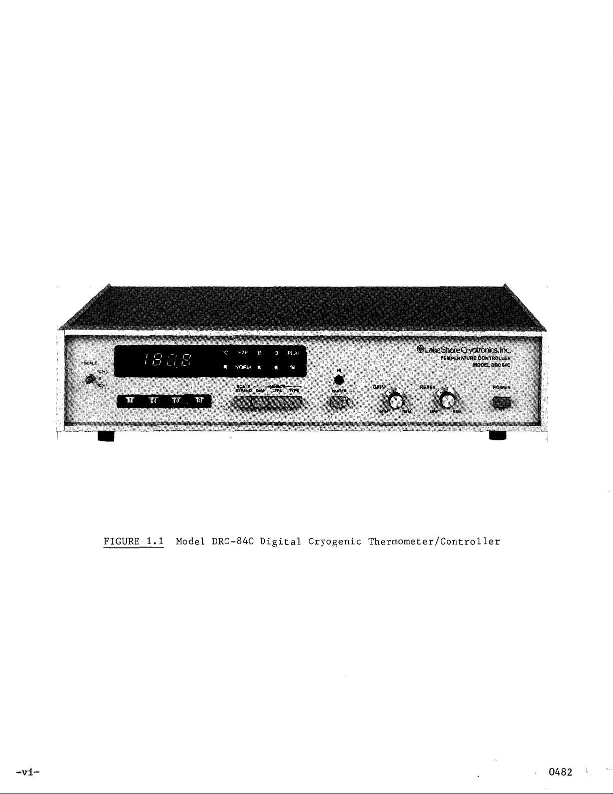
FIGURE
1.1
Model DRC-84C Digital Cryogenic Thermometer/Controller
SECTION
I
General Information
1.1
Introduction
The following is a description of the DRC-84C Cryogenic Digital
Thermometer/Controller. The DRC-80 Series of instruments is designed to be
used with the Model DT-500-DRC and DT-500CU-DRC-36 silicon diode sensors
manufactured by Lake Shore Cryotronics, Inc.
Several different diode sensor curves are designed for use with this
instrument. When ordering replacement sensors, care must be taken to assure
that the correct sensor curve is specified. Multiple curves are needed
that Lake Shore can assure the customer that replacement sensors
will
so
be
available at any time in the future. For details, please see Section 1.4.
This controller
will
also use the PT-101,
102,
103 Series of platinum
resistance thermometers which are available from Lake Shore Cryotronics,
Inc. The data sheet for these sensors is included in the back of this manual.
1.2 Description
The DRC-80 Series is comprised of completely self-contained units
providing direct digital readout in Kelvin temperature units and, for the
controllers, temperature control by direct analog comparison between the
sensor voltage and an analog equivalent of the digital temperature set point.
The Lake Shore DRC-84C utilizes two temperature sensor technologies to
achieve its wide range: Silicon diodes for the low range (1.4-330K), and
platinum RTD's for higher temperatures (30-800K). Each sensor type has its
own input section which contains appropriate sensor excitation sources,
signal conditioning, and switching.
A
microprocessor
in
the 84C determines
the temperature based on the input section activated, the sensor signal, and
the sensor-response curve stored in internal memory. Additionally, the micro-
processor generates a voltage equivalent to the control set-point temperature
for the sensor in use. Comparison of that voltage with the actual sensor
voltage produces the error signal which is the basis
of
the 84C's analog
control.
Each input section of the DRC-84C features dual-sensor input which
enables two sensors to be used concurrently. Either sensor can be selected
to be the control sensor and/or the temperature display sensor (both sensors
must be of the same type
can be centered at one point
-
silicon diodes or platinum RTD's). Thus control
in
a system and temperature monitored elsewhere.
This permits, for instance, maintenance of temperature at a particular cold
stage and simultaneous measurement of sample temperature. Selection of input
section as well as display and control sensor is made via front-panel push-
but tons.
-1-
A 4-digit display clearly and unambiguously shows the temperature
directly in Kelvin or Celsius with 0.1 degree resolution. At low temperatures
(under 30K) a SCALE EXPAND mode increases resolution to 0.01K for monitoring
trends and other relative temperature measurements. Absolute accuracy at
low temperatures is ±0.5K in either mode.
The silicon-diode input section of the DRC-84C is designed to use proven
Lake Shore DT-500 Series DRC-curve silicon-diode Sensors, which provide
measurement accuracy to ±0.5K at low temperatures. Accuracy can be increased
to better than ±0.1K through use of an individually calibrated sensor and
the DRC-Precision option to store the calibration. Any DT-500 Sensor can
be utilized in the latter case.
Lake Shore PT-100 Series 100-ohm Platinum RTD's are the ideal Sensors
for the platinum section. The standard response curve is based on 0.1%
interchangeability at
0.00835/°C.
The curve conforms to DIN standard 43760 and is published in
°
0
C and a temperature coefficient
(0
to 100°C) of
the Lake Shore PT-100 Technical Data sheet. Custom calibrations are available and can be incorporated into the 84C via the DRC-Precision option.
Since silicon-diode sensors can be damaged by exposure to temperatures
above 380K (DT-500DRC Sensors should not be used above 330K to prevent deterioration of their epoxy seals), precautions are recommended in designing
systems for operation at higher temperatures. The preferred approach is to
have diode sensors installed only when the system is operated below room
temperature. Special software limits and error codes are generated if the
instrument is set to control a point above or below the silicon diode or
platinum sensor temperature limits (see Section 3.13
-
Table of Error Condi-
tions).
Control temperature is easily selected and read directly in Kelvin
or Celsius on front-panel digital thumbwheel switches and an adjoining scaleselect switch. The switches provide quick and constant display of the set
point with a resolution of 0.1K or C. Temperature controllability is a
function of system design; and performance is often better than
°
0.1
degree.
Both the gain and reset are variable, and can be set from the front
panel to enable the Controller to be precisely tuned to match the system
response over any temperature region. Ample gain and reset have been
designed in to assure fast response, low offset error, and high stability.
Two heater output levels are selectable on the DRC-84C.
Th
HI
mode
provides up to 25 watts of heater power while the LO mode limits output power
to a nominal 10 watts.
Five options are available with the DRC-80 Series of instruments. One
option
is
an analog signal which is proportional to temperature (DRC8-L/A).
This option has a sensitivity of 10 mV/K.
A second option is a ten-position switch (SW-10A) for multiple sensor
readout. This switch is a separate half-rack box which plugs into the Sensor
"B" position of the DRC-84C. The sensor selected is also identified via
digital interface of the DRC-84C, if present.
-2-
Another option
corresponds to the calibration curve of the customer's DT-500 Series sensor.
A
combination of a calibration and custom cut PROM
accuracy to nearly
any sensor may be used with this option,
stricted to the
DRC
is
a
custom cut PROM (DRC-Precision Option) which
will
±.1
Kelvin over the calibrated range. Please note that
i.e.,
Series sensors.
the customer
increase display
is
not
re-
There
set-point, the gain and
and sensor selected from the
format while the
The DRC-80 Series
ciated support circuits. The
up to 32 break points per curve. The data consists of
and voltage associated with each break point.
can generate the
entire temperature range
±0.5K
1.3
thermometer-controller, the following:
at
Major Assemblies Supplied
The DRC-84C includes
A.
B.
C.
are
two programming options available; each
reset
DRC8-IEEE
is
DRC
curve to an accuracy of better than
Helium and Nitrogen temperatures and to
Operating and Servicing Manual
Four five Pin Plugs for Temperature Sensor Cables
One seven Pin Plug for Monitor of Sensor Output Voltage
and the
DRC8-L/A
as
well
SW-10A.
is
in the popular IEEE-488 format.
designed around a 3870 microprocessor and asso-
DRC
(4.0
-
400K). The
as
The
curve
output the displayed temperature
DRC8-BCD-I/O
is
stored in a PROM which can handle
These straight line segments
DRC
diodes match this curve to
±1.0K
as
standard equipment, in addition to the digital
option
will
is
a
at
control the
in a parallel
table of temperature
0.1
Kelvin over the
room temperature.
BCD
Model DT-500 Series silicon diodes or platinum thermometers
as
supplied
Complete Specifications, Accessory Equipment and Customs Options
listed in the front of the Manual.
1.4 Ordering of Replacement or Additional Sensors
Two
Model
DRC-36 sensors. Their description
sensor configurations
PROM
Series instruments.
instrument, you must be certain to order the correct curve
DRC-80
is
More than one
part of the
different sensor configurations
Series instruments. These
cut.
DRC-84C
are
available if the diode
curve presently
If
additional sensors
instrument.
are
available for use with the
are
the DT-500-DRC and the DT-500CU-
is
included elsewhere in this manual.
is
calibrated and a special
exists
which can be used with the DRC-80
are
ordered for use with your
so
that your
are
not
are
All
-3-
instrument will have its stated accuracy. The proper curve may be determined
in one of the following ways:
A.
Specify the sensor serial number that is currently being used
with the instrument (serial number is found on the end of the
plastic box in which the sensor was received).
B.
Specify the serial number of your instrument. Our records
will
indicate with which sensor the instrument is compatible.
C.
Remove the top of your instrument and observe the indicator
on
the
curve PROM.
D. The fourth way is to measure the diode voltage at
give this value to Lake Shore Cryotronics, Inc. when re-
ordering sensors.
Lake Shore PT-100-ohm Platinum RTD’s are available for the platinum
section. These thermometers have a
temperature coefficient
(0
to 100°C) of
0.1%
interchangeability at 0 C and a
0.00385/°C.
4.2K
and
°
-4-
SECTION II
Installation
2.1 Introduction
This section contains information and instructions necessary for the
installation and shipping of the model DRC-84C Cryogenic Temperature Indicator
and Controller. Included are initial inspection instructions, power and
grounding requirements, installation information and instructions for repackaging for shipment.
2.2 Initial Inspection
This instrument was electrically and mechanically inspected prior to
shipment. It should be free from mechanical damages, and in perfect working
order upon receipt. To confirm this, the instrument should be inspected visual-
ly for obvious damage upon receipt and tested electrically by use to detect any
concealed damage. Be sure to inventory all components supplied before discarding any shipping materials. If there is damage to the instrument in tran-
sit, be sure to file appropriate claims with the carrier, and/or insurance
company. Please advise the company
ages, please advise the company. The standard Lake Shore Cryotronics warranty
is given on the title page.
of
such filings. In case of parts' short-
2.3
ment is of the proper line voltage and fused accordingly. The line voltage and
fuse are shown on the rear panel of the instrument.
(S2
board of the unit.
2.4 Grounding Requirements
Association
and cabinets to be grounded. This instrument is equipped with a threeconductor power cable which, when plugged into an appropriate receptacle,
grounds the instrument.
2.5 Installation
generate significant heat. It may therefore be rack mounted in close proximity
to other equipment in dead air spaces. The heat from such adjacent equipment
should not subject the controller to an ambient temperature in excess of
Power Requirements
Before connecting the power cable to line voltage, insure that the instru-
The line voltage can be changed by switching line voltage selector switch
-
Figure
Nominal permissible line voltage fluctuation is
To protect operating personnel, the National Electrical Manufacturer's
The DRC-84C Thermometer/Controller is all solid state and does not
6.5
DRC-84C Component Layout) located on the main printed circuit
±10%
(NEMA)
at 50 to
recommends, and some local codes require, instrument panels
60
Hz.
-5-
50°C (122°F).
As
with any precision instrument,
it
should not be subjected
to the shock and vibrations which usually accompany high vacuum pumping
systems.
The recommended cable diagrams for the sensor diode and heater element
(in the case of the DRC-84C controllers) are shown in Figure 2.1 (a) and
(b).
The use of a four wire diode or resistor connections is highly recommended to
avoid introducing lead IR drops which
sensor cable connection is used. For example, for
diodes, every 25 ohms of cable resistance corresponds to a
Kelvin.
the diode
The alternate wiring scheme shown in Figure 2.1
in
less critical applications where lead resistance can be kept
will
occur if the alternate two lead
a
two lead connection with
.1K
error above
(c) may be used for
30
small. Because of the low resistance of platinum resistance thermometers, the
four lead cable connections must be used to obtain system accuracy. The indi-
cated shielding connections are the recommended standard practice to avoid
ground loops. Figure 2.1
output of sensor voltage (0-2.5V for diodes,
optional linear analog output of temperature
(d)
shows the monitor connections for the analog
0-3.0V
(0-BV,
for platinum, Pin
Pin C). In the case of
A)
and
the platinum resistor, the buffered output voltage is -20 times the actual
sensor voltage. For example, if the input voltage from the platinum sensor
is 0.0100V, then the buffered output voltage would be -0.2000V.
2.6 Repackaging for Shipment
Before returning an instrument to the factory, should repair be neces-
sary, please discuss the malfunction with a factory representative. He may be
able to suggest several field tests which will preclude returning a satisfactory instrument to the factory when the malfunction is elsewhere.
If
it
is
indicated that the fault is in the instrument after these tests, the represen-
tative will provide shipping and labeling instructions for returning
it.
When returning an instrument, please attach a tag securely to the
instrument itself (not on the shipping carton) clearly stating:
A. Owner and Address
B. Instrument Model and Serial Number
C. Malfunction Symptoms
D. Description of External Connections and Cryostats
If the original carton is available, repack the instrument in a
plastic bag, place in carton using original spacers to protect protruding
controls, and close carton. Seal lid with paper or nylon tape. Affix
mailing labels and "FRAGILE" warnings.
-6-
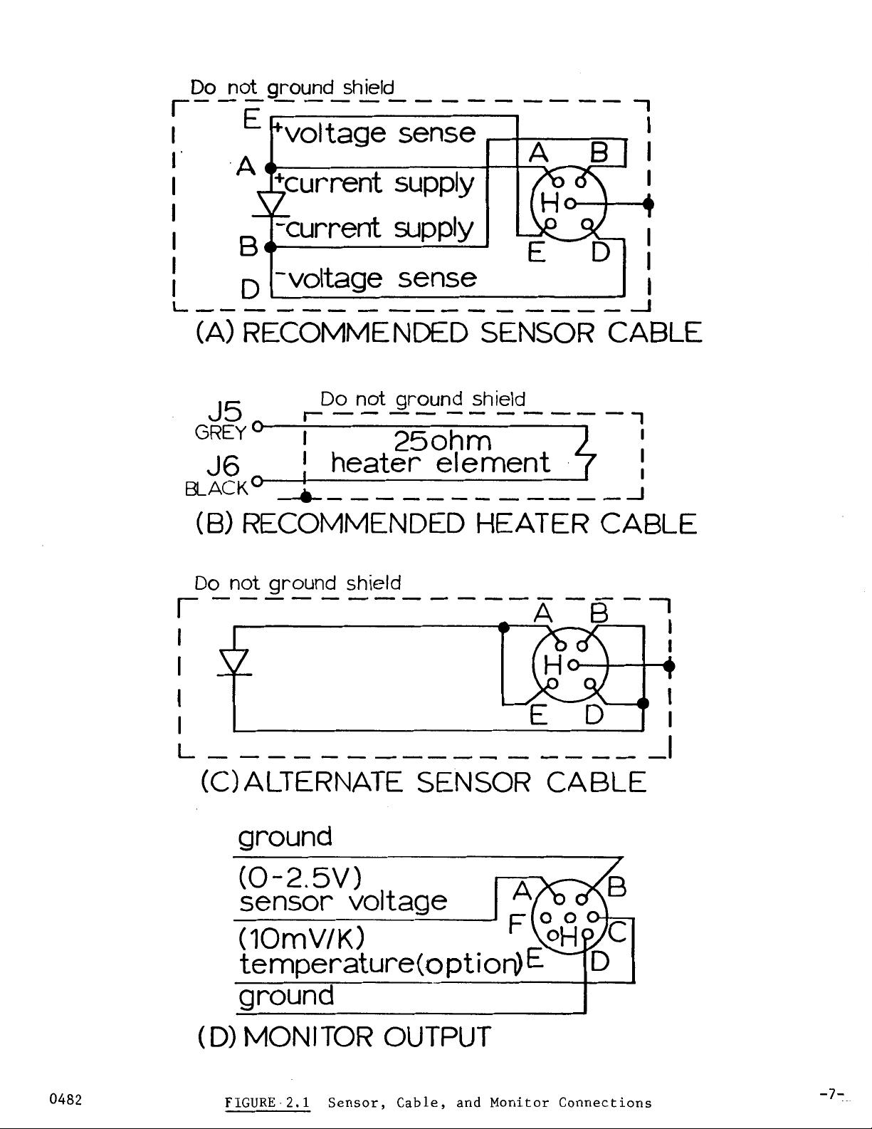
FIGURE.2.1
Sensor, Cable, and Monitor Connections
-7-
3.1 Introduction
SECTION III
Operating Instructions
This section contains a description
their adjustment under normal operating conditions, and typical controller
applications. These instructions are based upon the instrument having been
installed as outlined
2.1
(a),
in particular, must be correct. For the DRC-84C instrument, a 25
ohm heating element is assumed attached to the "Heater" terminals as shown
in Figure
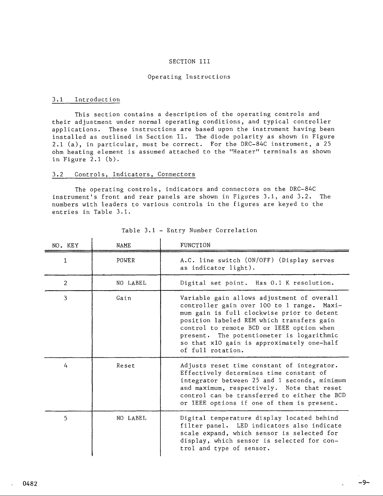
3.2 Controls, Indicators, Connectors
instrument's front and rear panels are shown in Figures 3.1, and 3.2. The
numbers
entries in Table 3.1.
NO. KEY
1
2
2.1
(b).
The operating controls, indicators and connectors on the DRC-84C
with
leaders to various controls in the figures are keyed to the
NAME
POWER
NO LABEL
in
Section
Table 3.1
II.
-
Entry Number Correlation
FUNCTION
A.C. line switch (ON/OFF) (Display serves
as indicator light).
Digital set point. Has 0.1 K resolution.
of
the operating controls and
The diode polarity as shown in Figure
3
4
5
Gain
Reset
NO LABEL
Variable gain allows adjustment of overall
controller gain over
mum gain is full clockwise prior to detent
position labeled REM which transfers gain
control to remote BCD or IEEE option when
present. The potentiometer is logarithmic
so
that x10 gain is approximately one-half
of full rotation.
Adjusts reset time constant of integrator.
Effectively determines time constant of
integrator between 25 and
and maximum, respectively. Note that reset
control can be transferred to either the BCD
or IEEE options if one of them is present.
Digital temperature display located behind
filter panel. LED indicators also indicate
scale expand, which sensor is selected for
display, which sensor is selected for control and type of sensor.
100
to 1 range. Maxi-
1
seconds, minimum
-9-

This
Page Intentionally Left Blank
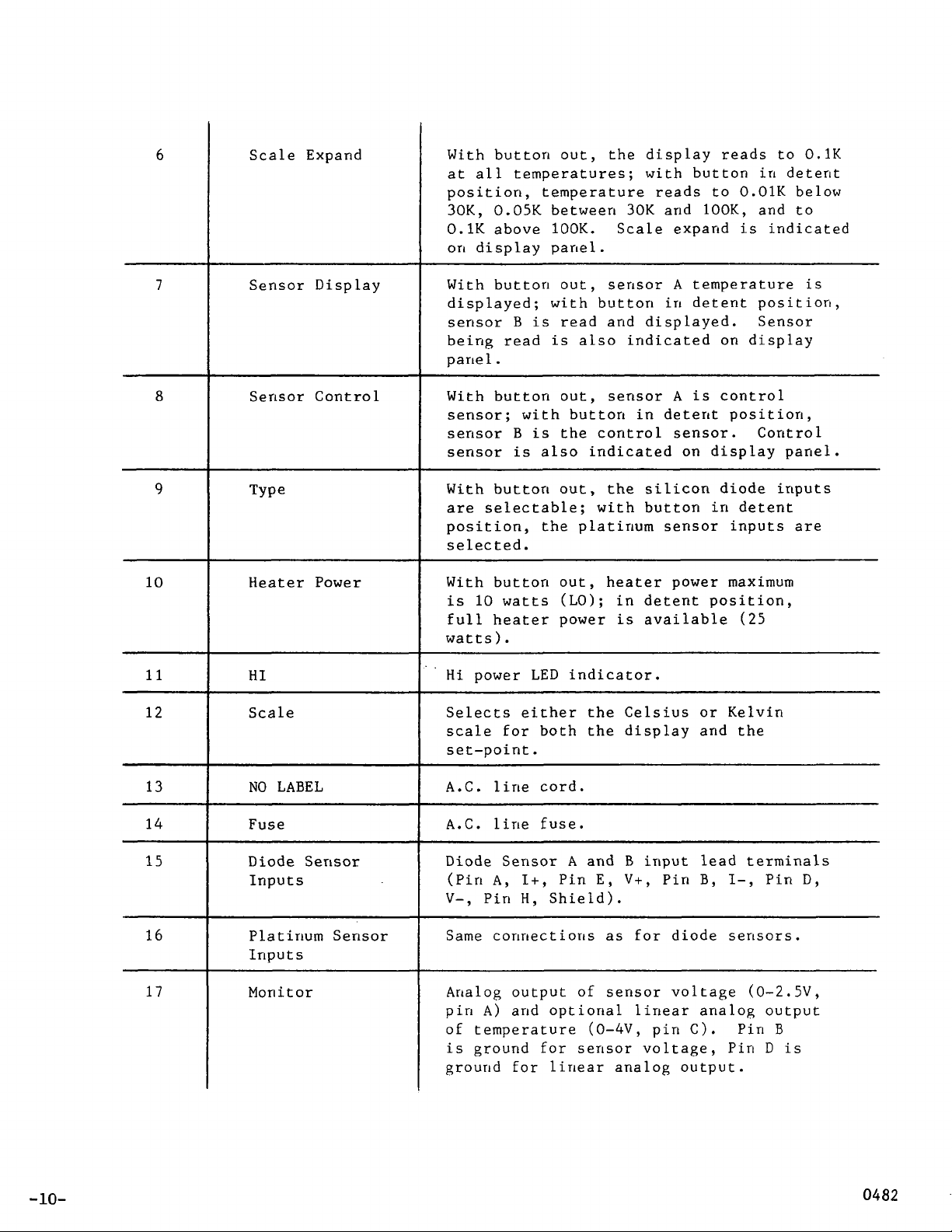
6
Scale Expand
With button out, the display reads to
at all temperatures; with button in detent
position, temperature reads to
30K,
0.1K
on
0.05K between
above
display panel.
100K.
30K
and
Scale expand
0.01K
100K,
is
0.1K
below
and to
indicated
7
8
9
10
11
12
Sensor Display
Sensor Control
Type
Heater
HI
Scale
Power
With buttori out, sensor
displayed; with button in detent position,
sensor
being read
panel.
With button out, sensor
sensor; with button in detent position,
sensor
sensor
With button out, the silicon diode inputs
are
position, the platinum sensor inputs are
selected
With button out, heater power maximum
is
full heater power
watts).
Hi
Selects either the Celsius or Kelvin
scale for both the display and the
set-point.
B
is
read and displayed. Sensor
is
also indicated on display
B
is
the control sensor. Control
is
also indicated on display panel.
selectable; with button in detent
.
10
watts (LO); in detent position,
is
power
LED
indicator.
A
temperature
A
is
control
available
is
(25
-10-
13
14
15
16
17
NO
LABEL
Fuse
Diode Sensor
Inputs
Platinum Sensor
Inputs
Monitor
A.C.
A.C.
Diode
V-,
Same connections
Analog output of sensor voltage (0-2.5V,
pin
of
is
ground for linear analog output.
line cord.
line fuse.
Sensor A and B input lead terminals
(Pin
A,
I+,
Pin
E,
V+,
Pin
B,
Pin
H,
Shield).
as
for diode sensors.
A)
and optional linear analog output
temperature (0-4V, pin C). Pin
ground
for
sensor voltage, Pin
I-,
Pin
B
D
is
D,
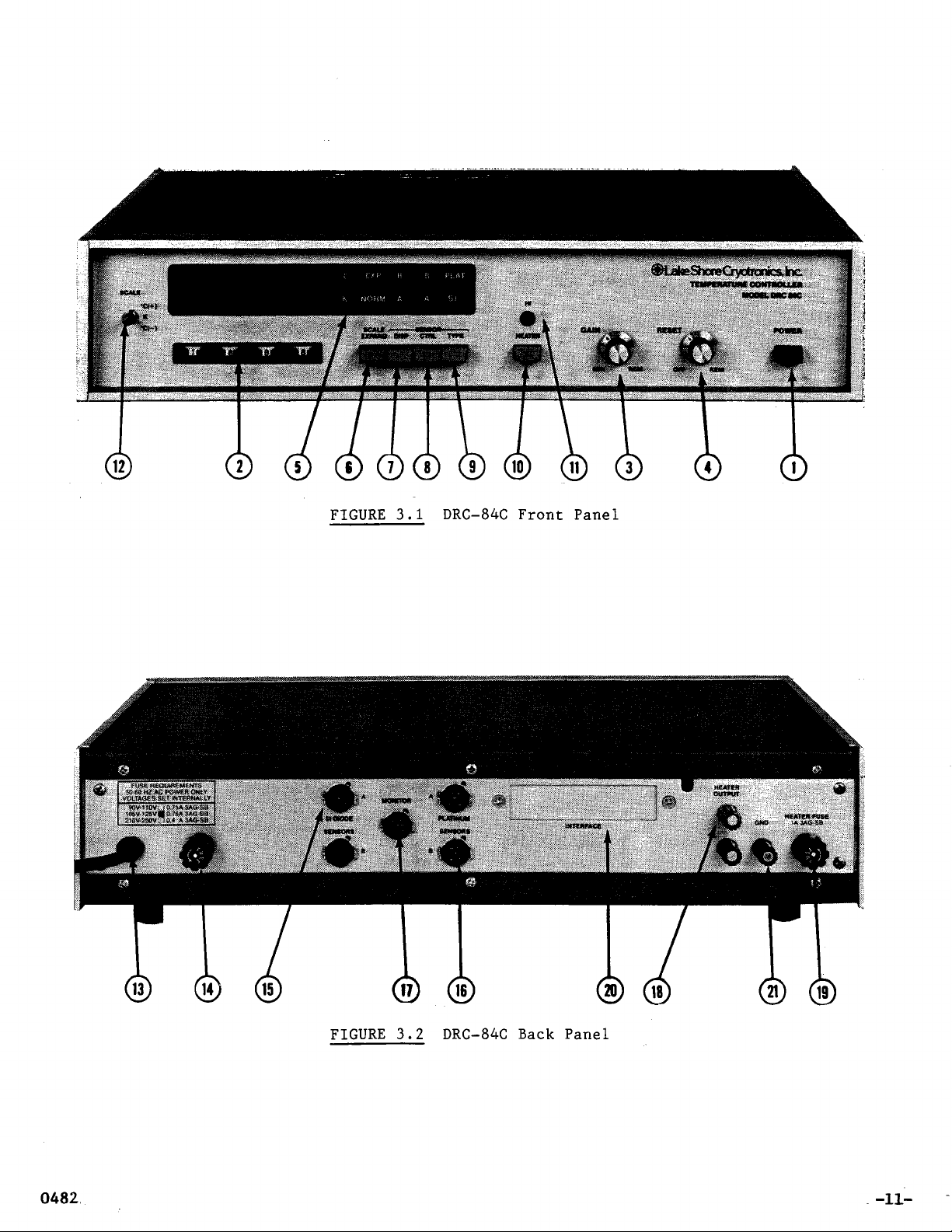
FIGURE
3.1
DRC-84C Front Panel
FIGURE
3.2
DRC-84C
Back
Panel
-11-

18
Heater
Heater element terminals (25 ohm heater
25
required for
watts of power).
19
20
Fuse
Interface
Output power fuse
(1.0
ASB specified).
BCD input of set point, gain and reset
output of temperature. Also IEEE
interface port.
21
GND
Instrument or case ground
3.3 Temperature Readout
The sensor(s) and heater should be installed following the
suggestions listed
in
the "Installation and Application Notes for
Cryogenic Sensors" brochure in Section VIII.
Connect the sensor(s) to the instrument following the diagram in
Figure 2.1.
Depress the power switch and observe that the display shows the
proper temperature relative to the sample temperature.
If the diode or lead wires are shorted or if the diode is connected
backwards, the display
an open current or voltage lead, the display
will
read
(----)
and flash 428.0.
will
slowly drift higher in
In
the case of
temperature from the last voltage reading taken by the A/D converter.
The sensor and readout display for diodes should follow Table 3.4
which illustrates typical values expected of the standard DT-500-DRC or
DT-500CU-DRC-36sensors for your appropriate curve.
The DIN standard curve for the platinum sensors is given in Table 3.7.
If the instrument or sensor does not agree with values listed in the
table, within the accuracy of the system, consult sections on installation
and/or section on troubleshooting to determine the cause and cure of the
malfunction. If an error code is displayed, refer to Section 3.13 for
possible corrections.
3.4 Analog Control
The digital set point of temperature is converted to an analog set
point of voltage which is then compared to the sensor voltage by summing
two respective currents of opposite sign.
To familiarize yourself with the DRC-84C control section, set the
instrument
so
that you are reading and controlling with the same sensor.
Turn the reset (integral) control section off. Establish a set point
temperature several degrees above the display temperature. Gradually
turn the gain clockwise from a minimum position. Note that as the gain
is increased, the offset between the display temperature and the set point
-12-
will
be decreased. The gain potentiometer is logarithmic with rotation and
covers a
100
to 1 range
minimum gain.
so
that the gain at mid-rotation is ten times the
With most systems, an oscillation in temperature
clockwise rotation. Further clockwise rotation
will
will
occur at some
cause a wild oscillation in temperature. The gain should then be backed off until a stable
control temperature occurs. Note that an offset between display temperature and set point will still be present.
Finally, turn on the reset control. With the addition of reset, the
temperature error between setpoint and control temperature should reduce to
zero. The rate at which this reduces to zero is determined again by a
clockwise rotation with the shortest time constant occurring at full clockwise rotation.
Note that the system can become unstable again with too much reset
added.
Slight variations in the gain and/or reset should give stable
temperature control.
The
HI-LO
tion increasing the gain by a factor of approximately two.
necessary when changing from
power switch also changes the loop gain with the
It
may be
LO
to
HI
power setting to reduce the gain
HI
posi-
slightly to compensate for the increased overall loop gain.
3.5 Analog Output of Temperature
The analog output of temperature takes the display temperature and
converts
it
to an analog signal which has a sensitivity
of
10 mV/K under
normal operation. The analog output voltage is located on the monitor
connector (Key
17
of
Figure 3.2). See Section 3.10 for installation notes
on DRC-8-L/A.
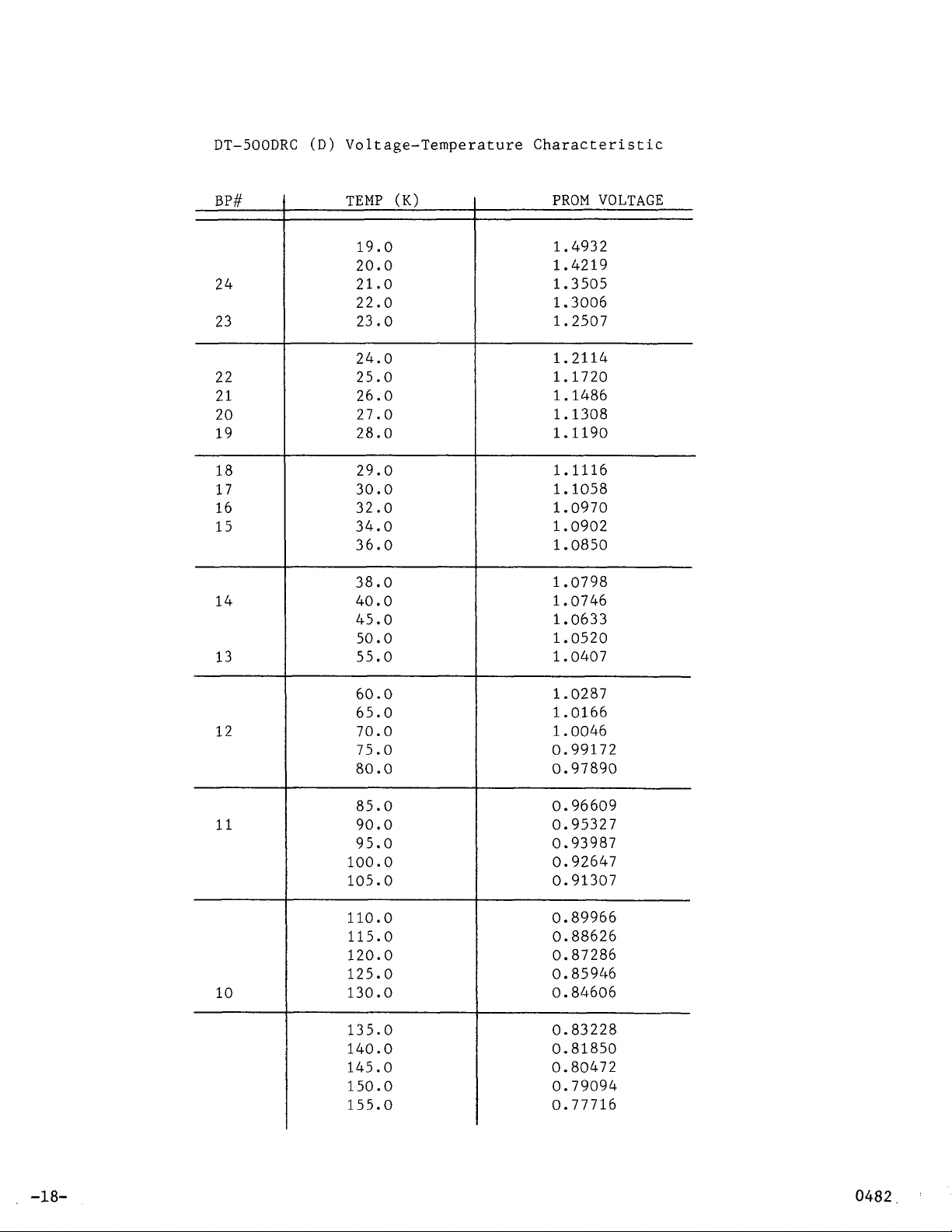
3.6 Standard DT-500-DRC and DT-500CU-DRC-36 Curves
The standard DT-500-DRC and DT-500CU-DRC-36 curve is explained in
Section 3.3. The Tables include a list of PROM sensor voltages and breakpoints used in the linearization
of
the DRC curve to arrive at the correct
temperature readout.
3.7 The 10-Sensor Selector Switch
The 10-Sensor Selector Switch includes an umbilical which ties to the
DRC-84C main printed circuit board (via a 16-pin ribbon cable header which
plugs into internal socket JC (see Figure 6.5, DRC-84C Component Layout)
and a cable to connect the selected sensor leads to the DRC-84C (Sensor
Plug
B
is either Key 15 or Key
16
of
Figure 3.2).
The SW-10A is supplied with an 18" cable which is shielded and has
male 5-pin amphenol connectors at each end. This cable connects between
-13-
J11 of the SW-10A and one of the B sensor plugs of the DRC-84C. Sensors
are connected to the SW-10A via printed circuit edge J10.
A
36-pin edge
card connector and hood has been supplied with the SW-10A. Connectors to
this edge J10 are given in Table 3.5.
3.8 Remote Parallel BCD Input/Output Option
The BCD option consists of a
along with a scale expand
bit
to indicate decimal point, a 15 bit parallel
16
bit
parallel output of temperature
input of set point in Kelvin degrees or Celsius (depending on switch position), a
reset setting, and a
4
bit parallel input of gain setting, a 4 bit parallel input of
4
bit output
of
switch position from the SW-10A.
Table 3.6 can be used for input and output line coding.
The BCD in and out is handled through connector
panel as INTERFACE), a
50
pin connector on the rear panel of the instrument.
Two internal jumper wires are placed on the printed circuit board
J4
(denoted on back
in
front
of internal connector JE. Cutting these jumpers allows the user to enable
the remote set point by setting Pin 38,
J4
high (see Table 3.6). If the
option was installed prior to shipment, these jumpers have already been cut.
Options that are field installed need to have their jumpers cut by the user.
Data latches internal to the instrument provide a 1-2-4-8 code using
positive logic with standard TTL levels of
0)
and 2.4 volts or higher for the high (or 1) state under full load con-
0.4
volts or less for low (logic
ditions. The drivers are sufficient to drive two standard loads, 3.2mA,
in
the low state.
Set point is input to the instrument via a remote set point enable
pin (externally generated,
pin
38). With no connection made to the external
enable pin, the option selects the internal (front panel) set point. When
the unit is receiving a set point externally, the front panel set
point switches are disabled.
-14-
The sensor temperature output
is
externally gated through the use of
an internally generated data valid pulse.
Input of gain value and reset can be seen
(highs are denoted as
"1"
and lows are denoted as
in
the following tables
"0").
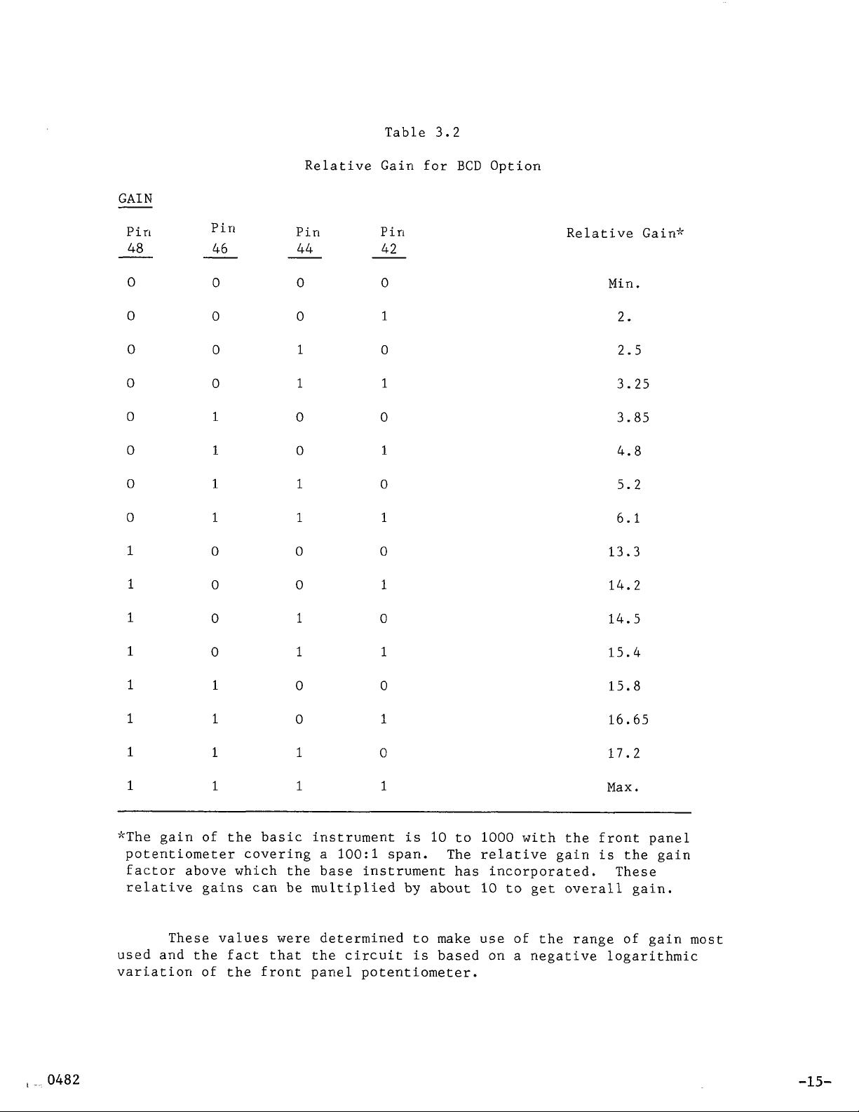
Table
3.2
Relative Gain for
GAIN
Pin Pin Pin Pin
48 46
0
0
0
0
0
0
0
0
1
0
0
0
0
1
1
1 1
1
0
44 42
0
0
1
1 1
0
0
1
0
0
1
0
0
1
0
1
0
BCD
Option
Relative Gain"
Min.
2.
2.5
3.25
3.85
4.8
5.2
6.1
13.3
1
1
1
1
1
1
1
0
0
0
1
1
1 1
1 1
0
1
1
0
0
1
0
1
0
1
0
1
"The gain of the basic instrument is
potentiometer covering a
100:1
span. The relative gain is the gain
10
to
1000
with the front panel
14.2
14.5
15.4
15.8
16.65
17.2
Max.
factor above which the base instrument has incorporated. These
relative gains can be multiplied by about
These values were determined to make use
10
to get overall gain.
of
the range of gain most
used and the fact that the circuit is based on a negative logarithmic
variation
of
the front panel potentiometer.
-15-
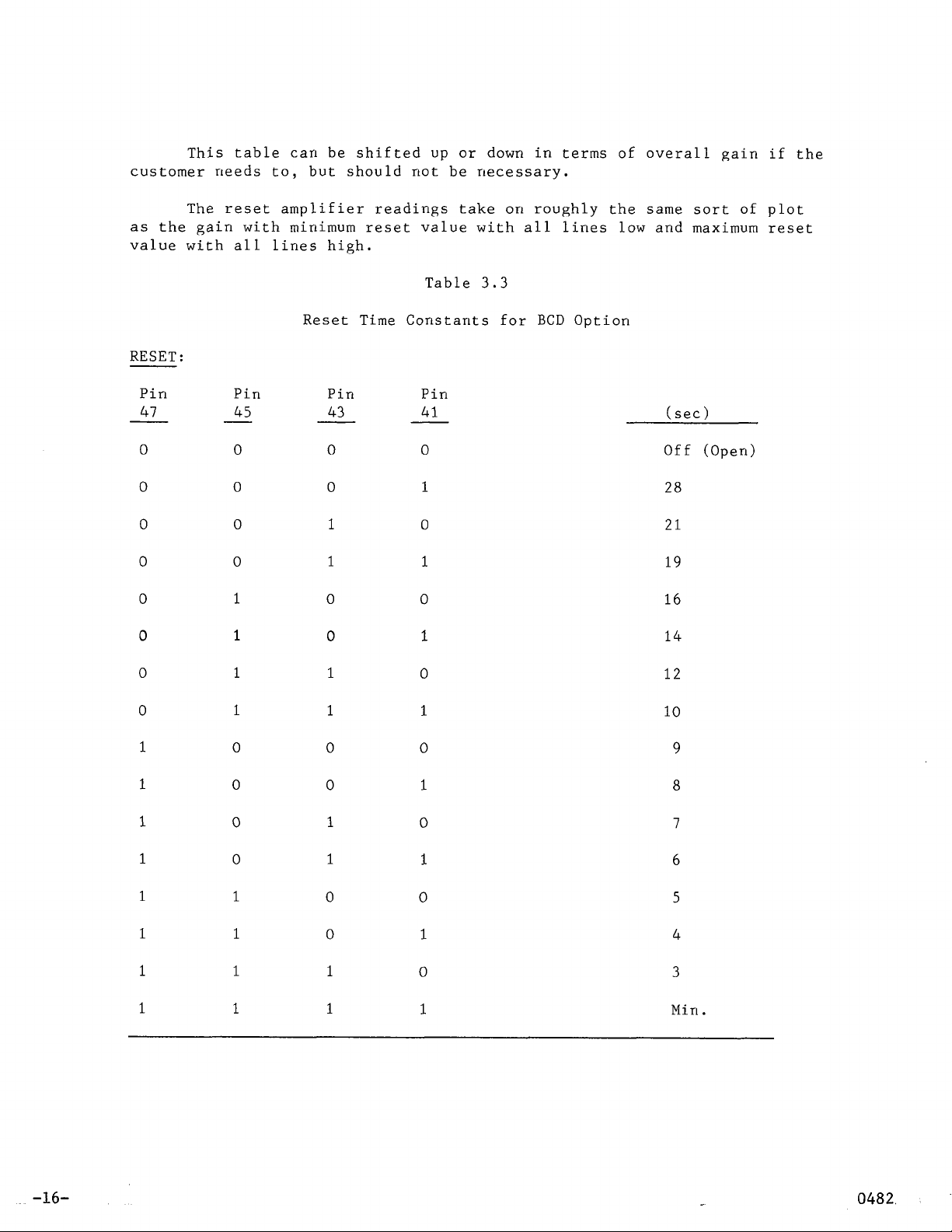
This table can be shifted
up
or down in terms
customer needs to, but should not be necessary.
of
overall gain
if
the
The reset amplifier readings take on roughly the same sort
of
plot
as the gain with minimum reset value with all lines low and maximum reset
value with all lines high.
Table
3.3
Reset Time Constants for BCD Option
RESET:
Pin Pin Pin Pin
41
0
0
0
0
0
0
45
0
0
0
0
1
1
43
0
0
1
1
0
0
41
0
1
0
1
0
1
(sec)
Off (Open)
28
21
19
16
14
0
0
1
1
1
1
1
1
1
1
1
0
0 0
0
0
1
1
1
1 1
1
1
0
1
1
0 0
0
1
1
0
1
0
1
0
1
1
0
1
12
10
9
8
7
6
5
4
3
Min.
-16-
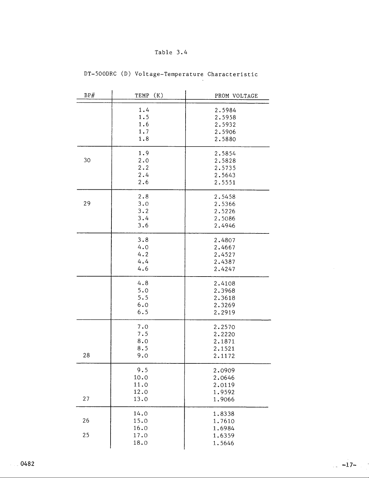
Table 3.4
DT-500DRC (D) Voltage-Temperature Characteristic
30
29
1.4
1.5
1.6
1.7
1.8
1.9
2.0
2.2
2.4
2.6
2.8
3.0
3.2
3.4
3.6
3.8
4.0
4.2
4.4
4.6
4.8
5.0
5.5
6.0
6.5
2.5984
2.5958
2.5932
2.5906
2.5880
2.5854
2.5828
2.5735
2.5643
2.5551
2.5458
2.5366
2.5226
2.5086
2.4946
2.4807
2.4667
2.4527
2.4387
2.4247
2.4108
2.3968
2.3618
2.3269
2.2919
28
27
26
25
7.0
7.5
8.0
8.5
9.0
9.5
10.0
11.0
12.0
13.0
14.0
15.0
16.0
17.0
18.0
2.2570
2.2220
2.1871
2.1521
2.1172
2.0909
2.0646
2.0119
1.9592
1.9066
1.8338
1.7610
1.6984
1.6359
1.5646
-17-
DT-500DRC (D) Voltage-Temperature Characteristic
24
23
22
21
20
19
18
17
16
15
14
13
12
19.0
20.0
21.0
22.0
23.0
24.0
25.0
26.0
27.0
28.0
29.0
30.0
32.0
34.0
36.0
38.0
40.0
45.0
50.0
55.0
60.0
65.0
70.0
75.0
80.0
1.4932
1.4219
1.3505
1.3006
1.2507
1.2114
1.1720
1.1486
1.1308
1.1190
1.1116
1.1058
1.0970
1.0902
1.0850
1.0798
1.0746
1.0633
1.0520
1.0407
1.0287
1.0166
1.0046
0.99172
0.97890
-18-
11
10
85.0
90.0
95.0
100.0
105.0
110.0
115.0
120.0
125.0
130.0
135.0
140.0
145.0
150.0
155.0
0.96609
0.95327
0.93987
0.92647
0.91307
0.89966
0.88626
0.87286
0.85946
0.84606
0.83228
0.81850
0.80472
0.79094
0.77716
 Loading...