

Lakeshore DRC-70, DRC-70C, DRC-7C User Manual
User’s Manual
Model
DRC-70
Digital Cryogenic Thermometer
Model
DRC-7C/-70C
Digital Cryogenic Controller
Obsolete Notice:
This manual describes an obsolete Lake Shore product. This manual is a copy from our
archives and may not exactly match your instrument. Lake Shore assumes no responsibility for
this manual matching your exact hardware revision or operational procedures. Lake Shore
not responsible for any repairs made to the instrument based
on
information from this manual.
is
Lake Shore Cryotronics, Inc.
575
McCorkle Blvd.
Westerville, Ohio
E-Mail Addresses:
sales@lakeshore.com
service@lakeshore.com
Visit Our Website:
www.lakeshore.com
Fax:
(61 4) 891 -1 392
Telephone:
Methods and apparatus disclosed and described herein have been developed solely on company funds of Lake Shore Cryotronics, Inc.
No
government or other contractual support or relationship whatsoever has existed which in any way affects or mitigates proprietary
rights
of
existing or applied for. Lake Shore Cryotronics, Inc. reserves the right to add, improve, modify,
modifications, or products at any time without notice. Lake Shore shall not be liable for errors contained herein or for incidental or
consequential damages
Obsolete
Lake Shore Cryotronics, Inc. in these developments. Methods and apparatus disclosed herein may be subject to US. Patents
in
connection with furnishing, performance,
Manual
43082-8888
(614) 891-2243
or
use
of
this
material.
USA
or
withdraw functions, design
October
1979
WA
LAKE SHORE CRYOTRONICS, INC. warrants each instrument of
its own manufacture to
and workmanship. Obligations under this Warranty shall
be limited to replacing, repairing
the purchase price, at
urned, shipment prepaid,
within ONE year of delivery to the original purchaser,
provided prior authorization for such return has been
given by an authorized representative of Lake Shore Cryotronics, Inc.
This
Warranty shall not apply to any instrument, which
inspection shall disclose to
become defective or unworkable due to abuse, mishandling,
misuse, accident, alteration, negligence, improper installation,
likewise shall not apply to any instrument or component
not manufactured by others and included in Lake Shore Cryo-
tronics, Inc. equipment; the original manufacturer's warran-
ty
Lake Shore Cryotronics reserves the right to make changes
in design at any time without incurring any obligation
to install same on units previously purchased.
or
is
extended
other causes beyond our control. This Warranty
to
be
our
Lake Shore Cryotronics, Inc. customers.
R
R
A
NTY
free from defects in material
or
giving credit for
option,
to
our
our
of
any instrument ret-
factory for that purpose
satisfaction, to have
our
THERE ARE NO WARRANTIES WHICH EXTEND BEYOND THE DESCRIPTION
ON THE FACE HEREOF. THIS WARRANTY IS IN LIEU OF, AND
EXCLUDES ANY AND ALL OTHER WARRANTIES OR REPRESENTATIONS,
EXPRESSED, IMPLIED OR STATUTORY, INCLUDING MERCHANTABILITY
AND
FITNESS,
LIABILITIES OF LAKE SHORE CRYOTRONICS, INC., INCLUDING
BUT NOT LIMITED
PERSON,
SHORE CRYOTRONICS, INC. ANY ADDITIONAL OBLIGATION OR LIABIL-
ITY NOT EXPRESSLY PROVIDED FOR HEREIN EXCEPT IN WRITING DULY
EXECUTED BY
AS WELL AS ANY AND ALL OTHER OBLIGATIONS,
TO,
SPECIAL OR CONSEQUENTIAL DAMAGES. NO
OR
FIRM
CORPORATION
AN
OFFICER OF LAKE SHORE CRYOTRONICS, INC.
IS
AUTHORIZED TO ASSUME FOR LAKE
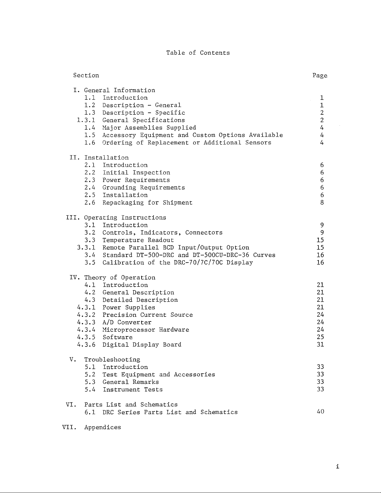
Table of Contents
Section Page
I.
General Information
1.1
Introduction
1.2 Description - General
1.3
Description - Specific
1.3.1
II.
III.
3.3.1
General Specifications
1.4
Major Assemblies Supplied
1.5 Accessory Equipment and Custom Options Available
1.6 Ordering
Installation
2.1 Introduction 6
2.2
Initial Inspection
2.3
Power Requirements 6
2.4 Grounding Requirements 6
2.5 Installation 6
2.6 Repackaging for Shipment
Operating Instructions
3.1
Introduction
3.2
Controls, Indicators, Connectors
3.3
Temperature Readout
Remote Parallel
3.4
Standard DT-500-DRC and DT-500CU-DRC-36 Curves
3.5
Calibration of the DRC-70/7C/70C Display 16
of
Replacement or Additional Sensors
BCD
Input/Output Option
1
1
2
2
4
4
4
6
8
9
9
15
15
16
IV.
V.
VI.
VII.
Theory
4.1
4.2
4.3
4.3.1
4.3.2
4.3.3
4.3.4
4.3.5
4.3.6
Troubleshooting
5.1
5.2
5.3
5.4
Parts
6.1
Appendices
of
Introduction
General Description
Detailed Description
Power Supplies
Precision Current Source
A/D
Converter
Microprocessor Hardware
Software
Digital Display Board
Introduction
Test
General Remarks
Instrument
List
DRC
Series
Operation
Equipment and
Tests
and Schematics
Parts
List
Accessories
and Schematics
21
21
21
21
24
24
24
25
31
33
33
33
33
40
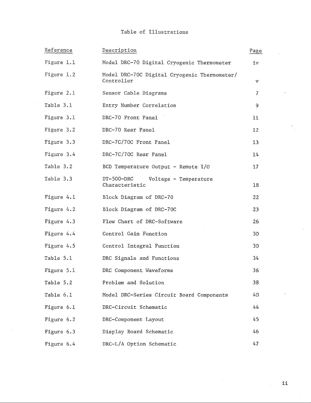
Table
Reference Description Page
of Illustrations
Figure
Figure 1.2 Model DRC-70C Digital Cryogenic Thermometer/
Figure 2.1 Sensor Cable Diagrams
Table
Figure
Figure 3.2 DRC-70
Figure 3.3 DRC-7C/70C Front Panel
Figure
Table 3.2
Table
Figure
Figure
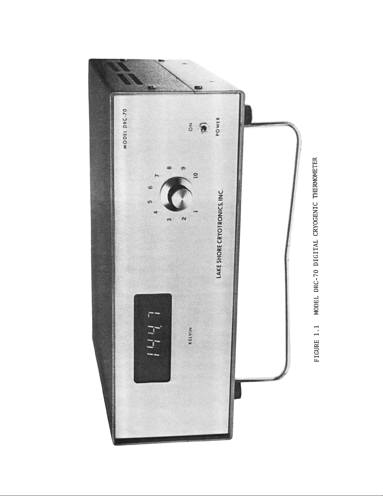
1.1
3.1
3.1
3.4
3.3
4.1
4.2
Model DRC-70 Digital Cryogenic Thermometer
Controller
Entry Number Correlation
DRC-70 Front Panel
Rear
DRC-7C/70C
BCD
Temperature Output - Remote
DT-
5
00-DRC Voltage - Temperature
Characteristic
Block Diagram
Block Diagram
Panel
Rear
of
of
Panel
I/0
DRC-70 22
DRC-70C 23
iv
V
7
9
11
12
13
14
17
18
Figure 4.3 Flow
Figure
Figure
Table
Figure
Table 5.2
Table
Figure
Figure 6.2
Figure 6.3 Display Board
Figure
4.4
4.5
5.1
5.1
6.1
6.1
6.4
Control Gain Function 30
Control Integral Function 30
DRC
DRC
Problem
Model
DRC-Circuit Schematic
DRC-Component Layout
DRC-L/A
Chart
Signals and Functions
Component Waveforms 36
DRC-Series
of
and Solution
Option Schematic
DRC-Software 26
34
38
Circuit Board Components
40
44
45
Schematic
46
47

SECTION
General Information
I
1.1
thermometer and
The DRC-7/70 series of instruments
DT-500-DRC and DT-500CU-DRC-36 silicon diode sensors manufactured by Lake
Shore Cryotronics, Inc.
this instrument. When ordering replacement sensors,
assure that the correct sensor curve
so
available
1.2
providing direct digital readout in kelvin temperature units and, for the
controllers, temperature control by direct digital comparison between the
displayed temperature, and a digital setpoint. The DRC-70 and DRC-70C display
temperature to
to
DRC
istics
Table
however, are useful to
Pre-selection allows the DRC-7/70
DT-500CU-DRC-36 sensors without adjustments of any kind. Since the standard
sensors
number of sensors with equal accuracy when selected
switch or multiplexer.
Introduction
is
a
The following
DRC-7C,
Several different diode sensor curves
that Lake Shore can assure the customer that replacement sensors
at
any
time
Description-General
The DRC-7/70
0.1
1
kelvin resolution.
The specified range
series
sensors which have been pre-selected to provide uniform character-
over this range. These sensors conform to the standard table (see
3.3)
to
0.5
are
interchangeable, the instruments may be used to read out any
series
kelvin resolution while the
R
or better over this temperature range. The instruments,
description of the DRC-70 cryogenic digital
DRC-70C cryogenic digital
are
designed to be used with the Model
is
specified. Multiple curves
in the future. For details, please
are
comprised of completely self-contained units
of
operation
1
K
although the accuracy
series
is
4.0
to be used with the DT-500-DRC and
thermometer/controllers.
are
designed for use with
care
must be taken to
see
DRC-7C
to
displays temperature
400
K*
utilizing standard
is
not
guaranteed below
through an appropriate
Section
are
needed
will
1.6.
be
4
K.
All
instruments contain a constant current source, for sensor excita-
is
tion, which
As
the sensor voltage. This allows the instrument user the ability to record the
sensor voltage versus
voltage directly. Since this output
recorder or voltmeter must be used to avoid loading
sensor
temperature may be determined to better than
One option
This
needs. Another option
for DRC-70 or
*
If possible, temperatures above
sensors since some
20
is
Four options
is
set
kelvin if heated above
preset
a
standard feature,
calibrated by the user or by
is
an analog signal which
to have
up
DRC-BCD-I/0
at
the factory
all
time
or to use a digital voltmeter to measure the sensor
at
units
is
Lake
10
microamps.
are
equipped with an analog output of
not buffered, a high input impedance
of
the sensor. If the
Shore Cryotronics, Inc.,
10mK.
are
available with the DRC-7/70
is
proportional to temperature (DRC-L/A).
a
sensitivity of
is
a
BCD
output of the displayed temperature (DRC-BCD-0
for the DRC-7C/70C). Included with the
330
of
these sensors may shift their values slightly below
330
kelvin.
10
mV/K
K
should be avoided with
but may be changed to the user's
series
of instruments.
BCD
DRC
series
output

option for the DRC-7C/70C instruments
the temperature
digital function generator. The third option
position, or ten position switch (DRC-SWreadouts. The DRC-70 has the switch mounted internally while the DRC-7C/70C
has the switch mounted in an external box. The fourth option
cut PROM (Programmable Read Only Memory) which corresponds to the calibration
curve of the customers DT-500
custom cut PROM
that any sensor may be used with this option,
restricted to the
set
point via
will
DRC
a
BCD
series
increase instrument accuracy to 0.1 kelvin. Please note
series
sensors.
is
the capability to remote program
signal from sources such
is
either a two position, five
2,
sensor.
5, or
A
10)
for multiple sensor
combination of calibration and
i.e.,
the customer
as
a
computer or
is
a
custom
is
not
1.3
instruments.
degrees with
designed system to
to 1 kelvin. Conformity to a standard
over the temperature range from 4.0 to 380
3850/3853 configuration and associated support circuits. The
stored in a PROM which can handle up to 32 break points. The data consists
of
straight line segments generate the
0.1
selected to conform to this curve to an accuracy
entire range.
1.3.1 General Specifications
when used with the standard DT-500-DRC or DT-500CU-DRC-36 temperature sensors.
Description-Specif
The following provides a description for the DRC-70 and DRC-7C/70C
The DRC-70 and DRC-70C provide direct temperature readout in kelvin
0.1
degree resolution. The DRC-70C controls in a properly
0.1
ic
kelvin. The DRC-7C has 1 degree resolution and controls
DRC
curve
is
better than 0.5 kelvin
K.
The DRC-7/70
a
table of temperature, voltage and slope between each break point. These
kelvin over the entire temperature range
The following specifications for the DRC-7/70
series
is
designed around an
DRC
curve to an accuracy
(4.0
F8
microprocessor using
DRC
of
better than
-
400
K).
of
better than
series
Sensors
0.5
are
curve
are
K
over the
applicable
a
is
General
Temperature Range:
Sensor: Silicon Diode (Model DT-500-DRC or DT-500CU-DRC-36)
Sensor Input:
Sensor Excitation:
Current Regulation: ±0.01%
Input Line Voltage:
Operating Environment:
Circuit Design: Integrated circuits, microprocessor controlled
:
1
to
400K
4
terminal connection, constant current excitation
Constant current 10 microamperes
115
V
10
-
45°C
(Accuracy not guaranteed below 4.0
or 230
V,
50
-
60
Hz,
switch selectable
K)
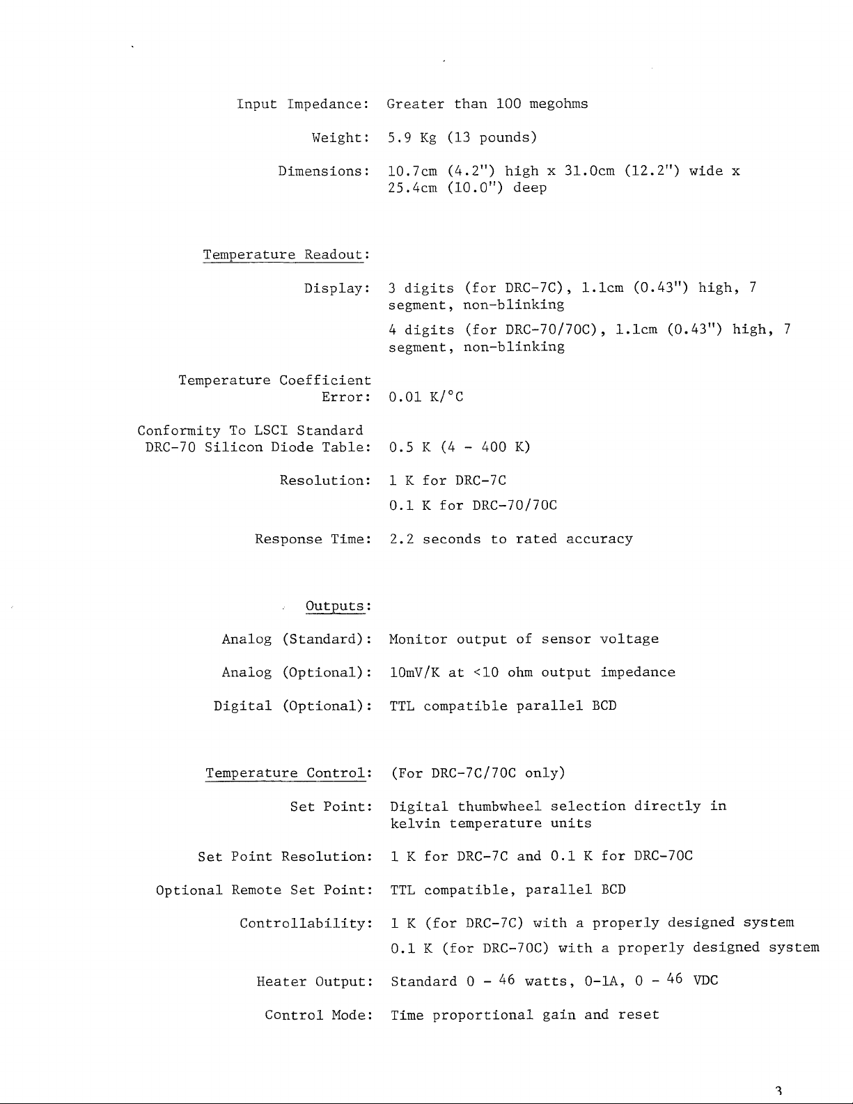
Input Impedance:
Weight:
Greater
5.9
Kg
than
(13
100
pounds)
megohms
Dimensions: 10.7cm
Temperature Readout:
Display:
Temperature Coefficient
Error:
Conformity To
DRC-70 Silicon Diode Table:
LSCI
Response
Standard
Resolution:
Time:
(4.2")
25.4cm
3
digits (for DRC-7C),
segment, non-blinking
4
digits (for DRC-70/70C),
segment, non-blinking
0.01
0.5
1
K
0.1
2.2
(10.01”)
K/°C
K
(4
for
DRC-7C
K
for DRC-70/70C
seconds to rated accuracy
high x 31.0cm
deep
-
400
K)
1.1cm
(12.2")
(0.43") high, 7
1.1cm
wide
(0.43") high,
x
7
outputs
Analog (Standard): Monitor output of sensor voltage
Analog (Optional): 10mV/K
Digital (Optional):
Temperature Control: (For DRC-7C/70C only)
Set
Point: Digital thumbwheel selection directly in
Set
Point Resolution:
Optional Remote Set Point:
Controllability:
Heater
Output:
:
at
<10
ohm output impedance
TTL
compatible parallel
kelvin temperature units
1
K
for DRC-7C and
TTL
compatible, parallel
1
K
(for DRC-7C) with a properly designed system
0.1
K
(for DRC-70C) with a properly designed system
Standard
0
-
46
watts,
0.1
BCD
K
for DRC-70C
BCD
0-1A,
0
-
46
VDC
Control Mode:
Time
proportional gain and
reset
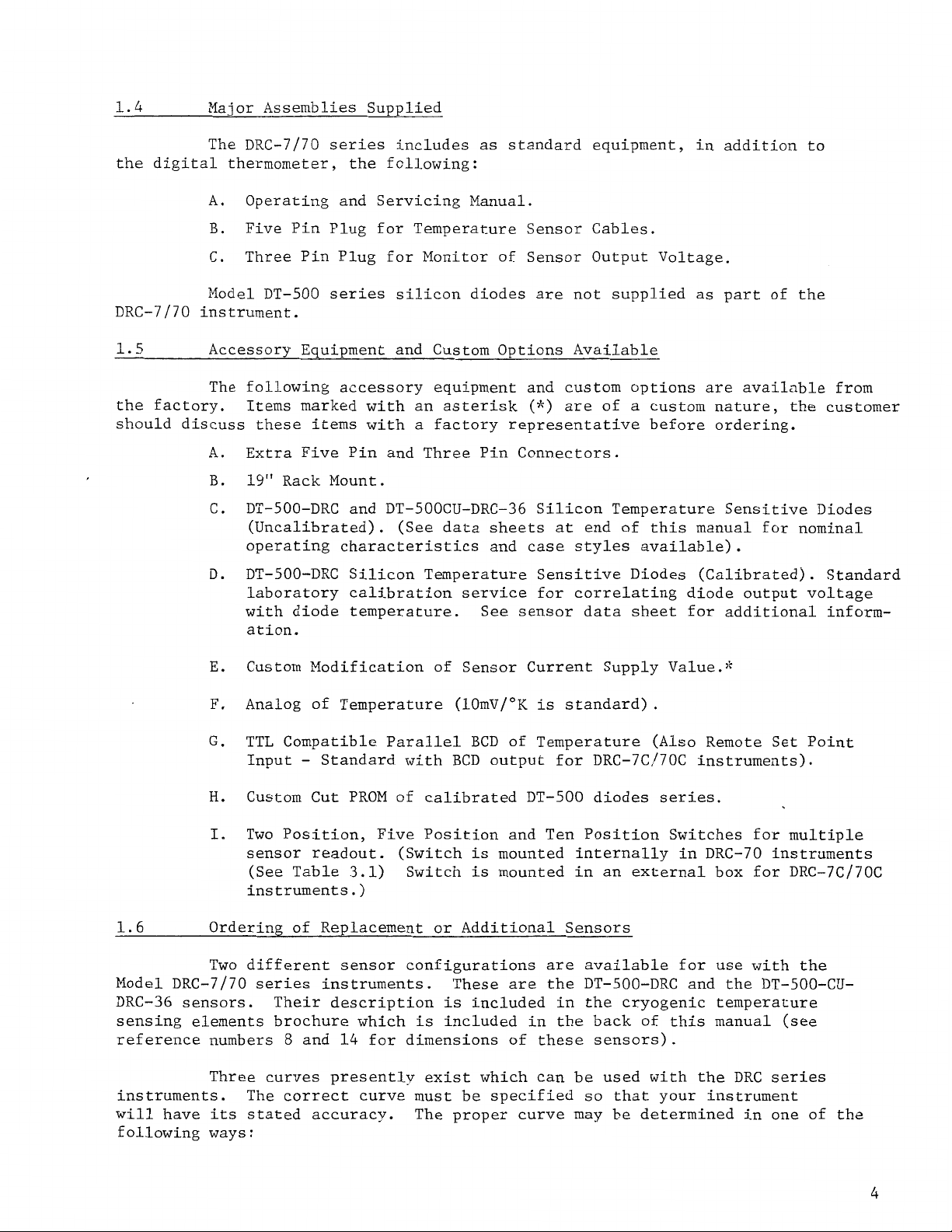
1.4
the digital thermometer, the following:
DRC-7/70 instrument.
Major Assemblies Supplied
The DRC-7/70 series includes as standard equipment, in addition to
A. Operating and Servicing Manual.
B.
Five Pin Plug for Temperature Sensor Cables.
C. Three Pin Plug for Monitor of Sensor Output Voltage.
Model DT-500 series silicon diodes are not supplied as part of the
1.5
the factory. Items marked with an asterisk
should discuss these items with a factory representative before ordering.
Accessory Equipment and Custom Options Available
The following accessory equipment and custom options are available from
(*)
are of a custom nature, the customer
A. Extra Five Pin and Three Pin Connectors.
B.
19"
Rack Mount.
C. DT-500-DRC and DT-500CU-DRC-36 Silicon Temperature Sensitive Diodes
(Uncalibrated). (See data sheets at end of this manual for nominal
operating characteristics and case styles available).
D. DT-500-DRC Silicon Temperature Sensitive Diodes (Calibrated). Standard
laboratory calibration service for correlating diode output voltage
with diode temperature.
ation.
E.
Custom Modification
F.
Analog of Temperature (10mV/°K is standard).
G.
TTL Compatible Parallel BCD
Input
H.
Custom Cut PROM of calibrated DT-500 diodes series.
-
Standard with BCD output for DRC-7C/70C instruments).
of
See sensor data sheet for additional inform-
Sensor Current Supply Value.*
of
Temperature
(Also Remote Set Point
I.
Two Position, Five Position and Ten Position Switches for multiple
sensor readout. (Switch is mounted internally in DRC-70 instruments
(See Table
instruments
1.6
Model DRC-7/70 series instruments. These are the DT-500-DRC and the DT-500-CUDRC-36 sensors. Their description is included in the cryogenic temperature
sensing elements brochure which is included in the back
reference numbers
instruments. The correct curve must be specified
will have its stated accuracy.
following ways
Ordering of Replacement or Additional Sensors
Two different sensor configurations are available for use with the
8
Three curves presently exist which can be used with the DRC series
:
and
3.1)
.
)
14
Switch is mounted in an external box for DRC-7C/70C
for dimensions of these sensors).
so
that your instrument
The proper curve may be determined in one of the
of
this manual (see
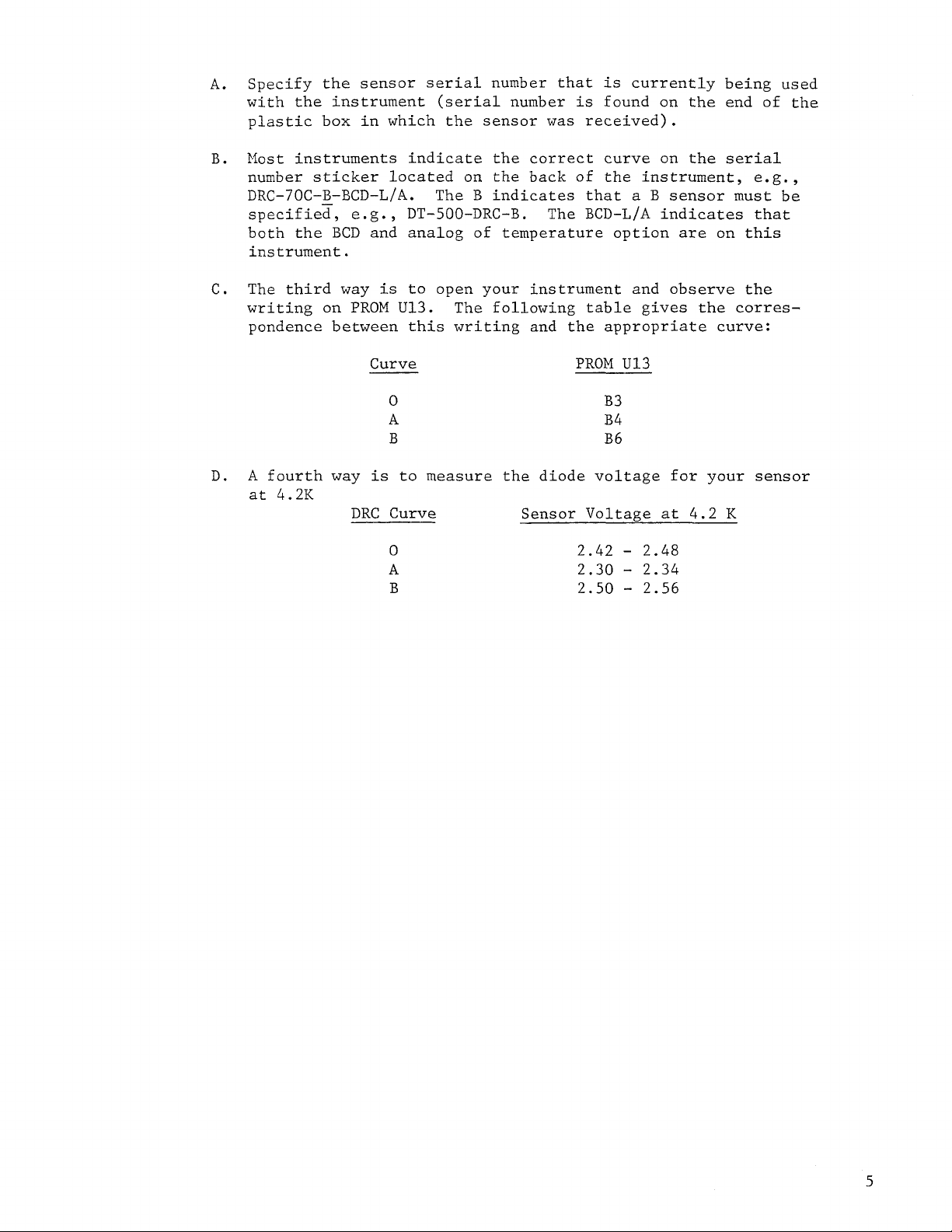
Specify the sensor
A.
with the instrument (serial number
plastic box in which the sensor
B.
Most instruments indicate the correct curve on the
number sticker located
DRC-70C-B-BCD-L/A.
specified,
both the
instrument.
C.
The third way
writing on
pondence between this writing and the appropriate curve:
e.
g
BCD
and analog of temperature option
PROM
Curve
serial
The B indicates that
.
,
DT-500-DRC-B.
is
to open your instrument and observe the
U13.
number that
was
on
the back
The
The following table gives the corres-
is
currently being used
is
found on the end of the
received).
of
the instrument, e.g.,
a
B
sensor must be
BCD-L/A
PROM
indicates that
are
U13
serial
on this
D. A
at
fourth way
4.2K
0
A B4
B B6
is
to measure the diode voltage for your sensor
DRC
Curve Sensor Voltage
0
A
B
B3
2.42
2.30
2.50
-
-
-
at
2.48
2.34
2.56
4.2
K
SECTION
II
Installation
2.1
Introduction
This section contains information and instructions necessary for the
installation and shipping of the model DRC-70/7C/70C Cryogenic Temperature
Indicators and Controllers. Included are initial inspection instructions,
power and grounding requirements, installation information and instructions
for repackaging for shipment.
2.2
Initial Inspection
This instrument was electrically and mechanically inspected prior
to
shipment.
It
should be free from mechanical damages, and in perfect working
order upon receipt. To confirm this, the instrument should be inspected
visually for obvious damage upon receipt and tested electrically by use
detect any concealed damage. Be sure
before discarding any shipping materials.
in transit, be sure
to
file appropriate claims with the carrier, and/or
to
inventory all components supplied
If
there is damage to the instrument
to
insurance company. Please advise the company of such filings. In case of
parts shortages, please advise the company. The standard Lake Shore Cryotronics
warranty is given on page iv.
2.3
Power Requirements
Before connecting the power cable to the line, ensure that the line
voltage selector switch
the line voltage to be used. Examine the power line fuse
is appropriate for the line voltage.
permissible line voltage fluctuation is
(115
V
or
230
V)
is in the appropriate position for
to
ensure that it
(115
V,
230
V
=
0.4
Amp) Nominal
±10%
at
50
to
60
Hz.
Caution: Disconnect line cord before inspecting or changing line fuse.
2.4
Grounding Requirements
To protect operating personnel, the National Electrical Manufacturer's
Association
and cabinets
(NEMA)
to
recommends, and some local codes require instrument panels
be grounded. This instrument is equipped with a three-conductor
power cable which, when plugged into an appropriate receptacle, grounds the
instrument.
2.5
Installation
The DRC-70 Thermometer and DRC-7C/70C Thermometer/Controller are all
solid state and do not generate significant heat.
It
may therefore be rack
mounted in close proximity to other equipment in dead air spaces. The heat
from such adjacent equipment should not subject the thermometer to an ambient
temperature in excess of 50°C
(122°F).
As
with any precision instrument, it
should not be subjected to the shock and vibrations which usually accompany
high vacuum pumping systems.
The recommended cable diagrams for the sensor diode and heater element
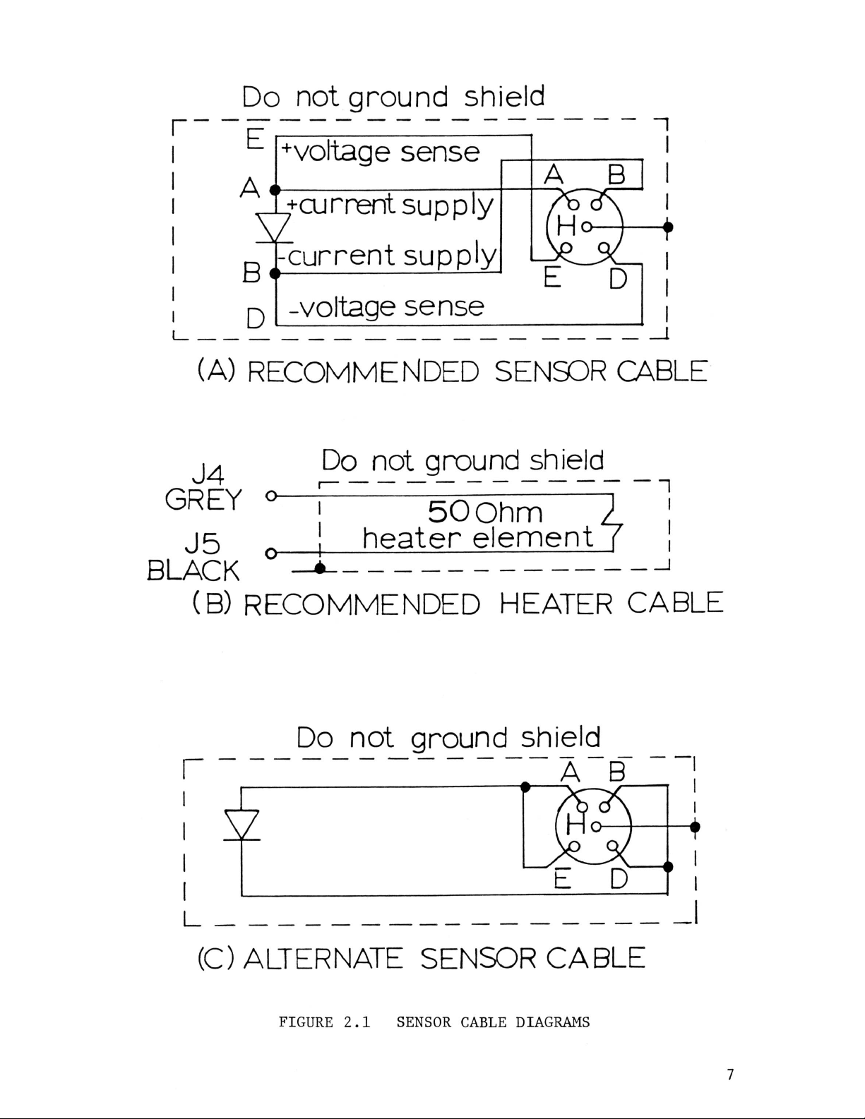
(in the case of the DRC-7C/70C controllers) are shown in Figure 2.1(a) and
(b).
introducing lead
The use of a four wire diode connection is highly recommended
IR
drops which will occur if the alternate two lead sensor
to
avoid
cable connection is used. For example, for a two lead connection, every 25
ohms of cable resistance corresponds to a
.1
K
error above
30
kelvin. The
alternate wiring scheme shown in Figure 2.1(c) may be used for the diode in
less critical applications where lead resistance can be kept small. The
indicated shielding connections are the recommended standard practice to
avoid ground loops.
2.6 Repackaging €or Shipment
Before returning an instrument to the factory for repair, please
discuss the malfunction with a factory representative.
He may be able to
suggest several field tests which will preclude returning a satisfactory
instrument to the factory when the malfunction is elsewhere. If it is
indicated that the fault is in the instrument after these tests, the repre-
sentative will send shipping instructions and labels for returning it.
When returning an instrument, please attach a tag securely to the
instrument itself (not on the shipping carton) clearly stating:
A.
Owner and Address
B. Instrument Model and Serial Number
C.
Malfunction Symptoms
D.
Description of External Connections and Cryostats,
If the original carton is available, repack the instrument in
plastic bag, place in carton using original spacers to protect protruding
controls, and close carton. Seal lid with paper or nylon tape. Affix
mailing labels and "FRAGILE" warnings.
If
the original carton is not available, wrap the instrument in
protective plastic wrapping material before placing in an inner container.
Place shock absorbing material around all sides
damage to protruding controls.
carton and seal with tape.
Place the inner container in a second heavy
Affix mailing labels and "FRAGILE" warnings.
of
the instrument to prevent
SECTION
Operating Instructions
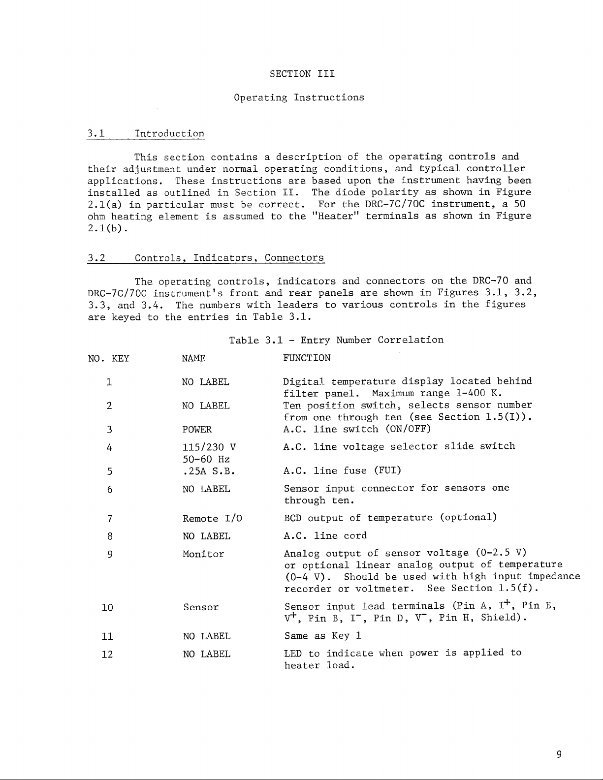
3.1 Introduction
a
This section contains
their adjustment under normal operating conditions, and typical controller
applications. These instructions
installed as outlined in Section
2.1(a) in particular must be correct.
ohm heating element
2.1(b).
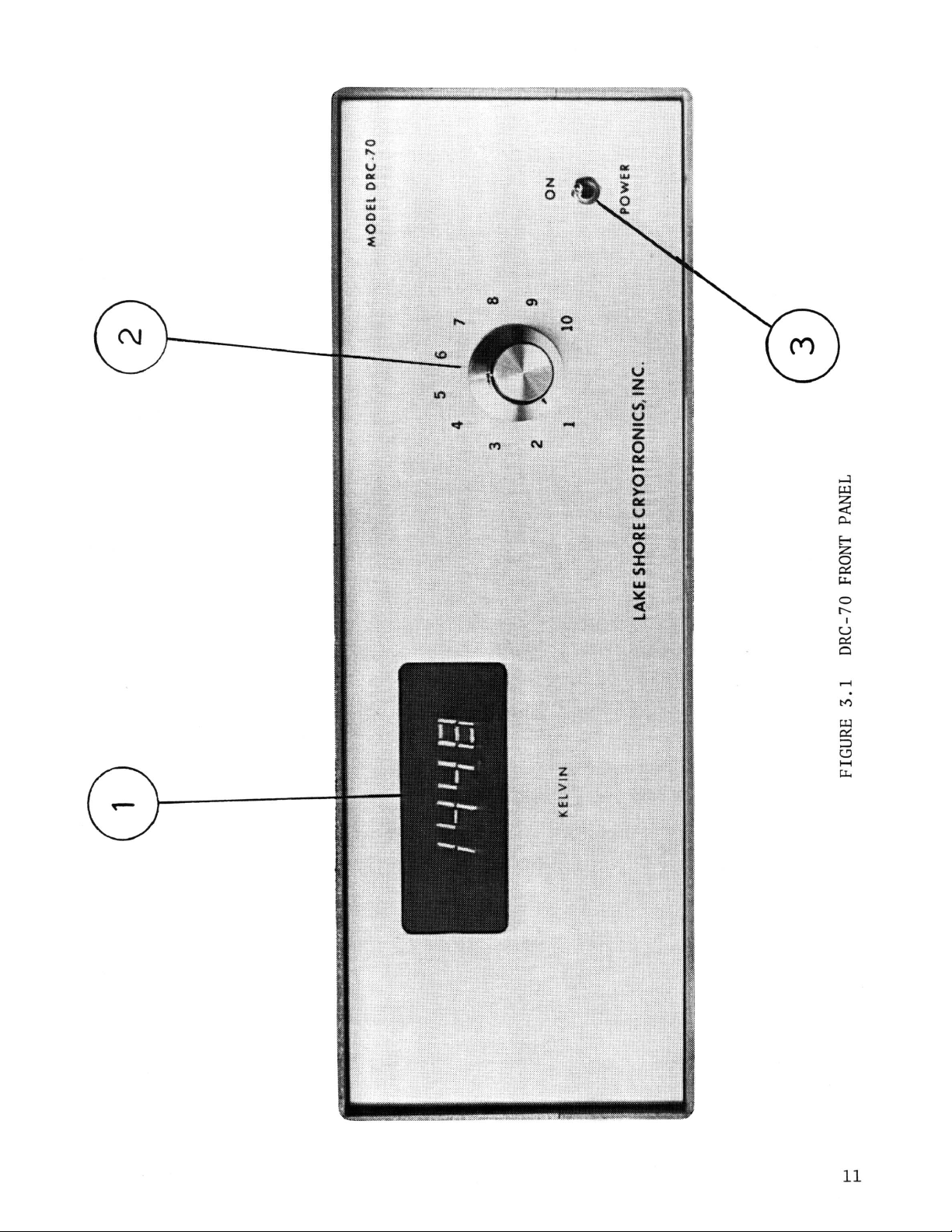
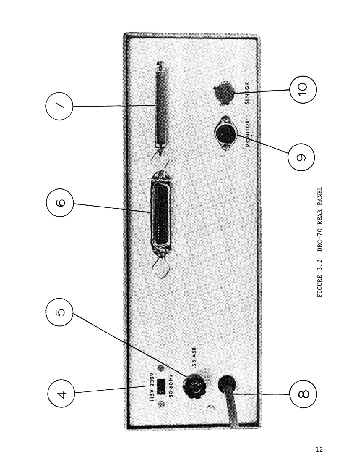
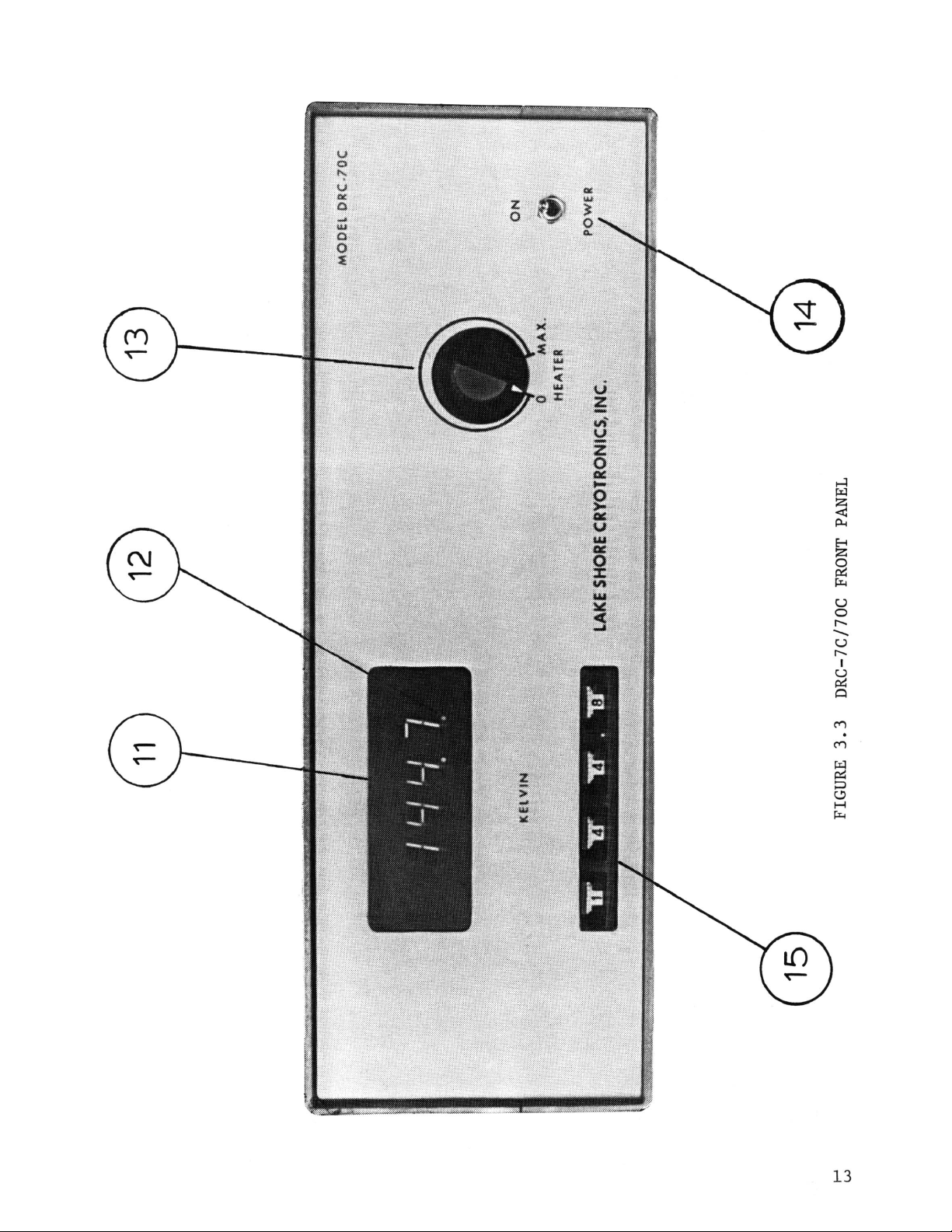
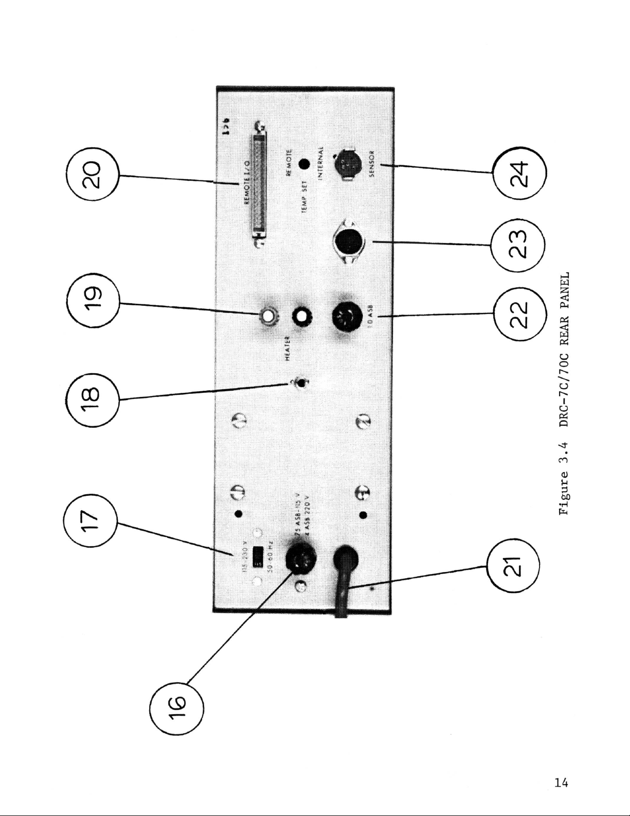
3.2 Controls, Indicators, Connectors
The operating controls, indicators and connectors on the DRC-70 and
DRC-7C/70C instrument's front and
3.3, and 3.4. The numbers with leaders
are
keyed to the entries in Table 3.1.
is
assumed to the
description of the operating controls and
are
II.
rear
III
based upon the instrument having been
The diode polarity
For the DRC-7C/70C instrument,
"Heater"
panels
to
terminals
are
shown in Figures 3.1, 3.2,
various controls in the figures
as
shown in Figure
as
shown in Figure
a
50
NO.
KEY
1
2
3
4
5 .25A
6
7
8
9
10
Table 3.1
NAME
NO
LABEL
NO
LABEL
POWER
115/230
50-60
NO
Remote
NO
Monitor Analog output of sensor voltage (0-2.5
Sensor
V
Hz
S.B.
LABEL
I/O
LABEL
-
Entry Number Correlation
FUNCTION
Digital. temperature display located behind
filter panel.
Ten position switch,
from one through ten (see Section 1.5(I)).
A.C.
A.C.
A.C.
Sensor input connector for sensors one
through ten.
BCD
A.C.
or optional linear analog output of temperature
recorder or voltmeter.
V+,
line switch (ON/OFF)
line voltage selector slide switch
line fuse
output of temperature (optional)
line cord
(0-4
V).
Sensor input lead terminals (Pin
Pin
B,
Maximum range
selects
(FUI)
Should be used with high input impedance
I-,
Pin
D,
V-,
1-400
sensor number
See
Section 1.5(f).
A,
Pin
H,
Shield).
K.
I+,
V)
Pin
E,
11
12
NO
NO
LABEL
LABEL
Same
as
Key
1
LED
to indicate when power
heater load.
is
applied to
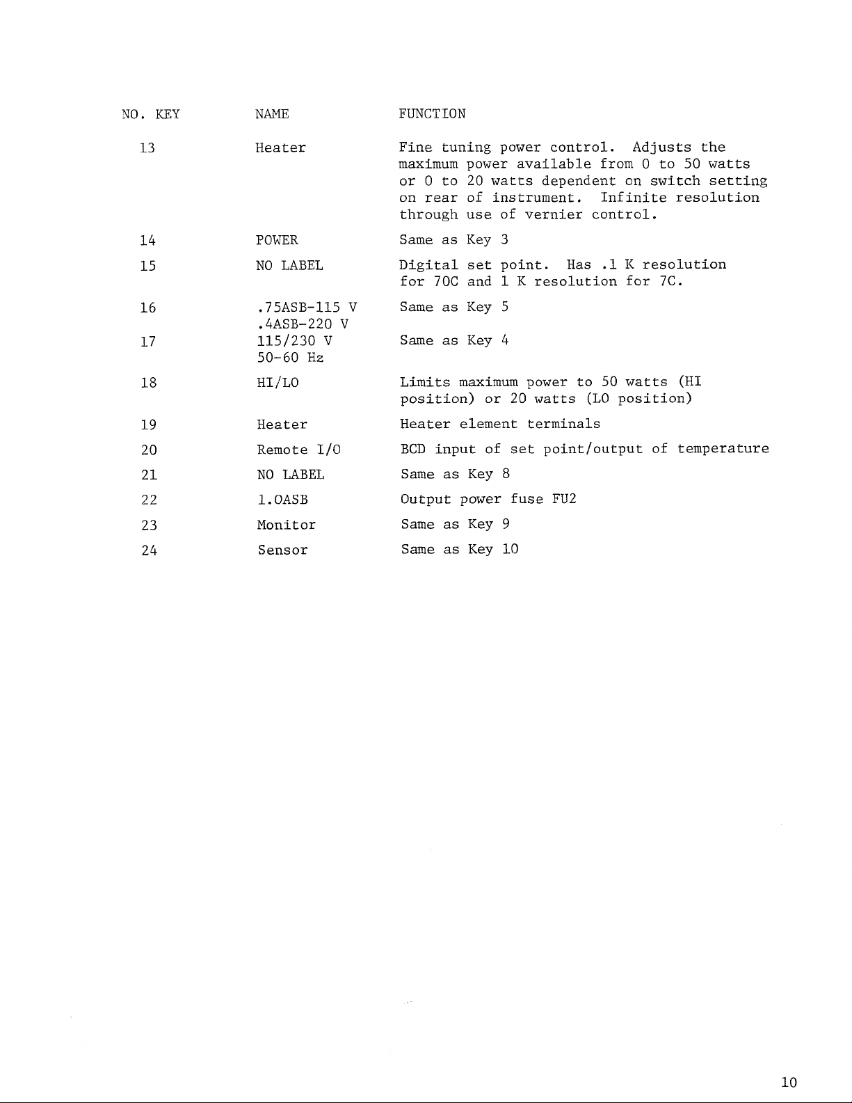
NO.
KEY
NAME
FUNCTION
13
14
15
16
17
18
19
20
21
22
23
24
Heater
POWER
NO
LABEL
.75ASB-115
.4ASB-220
115/230
50-60
HI
/LO
Heater
Remote
NO
1.
OASB
Monitor
Sensor
V
HZ
I/O
LABEL
V
V
Fine tuning power control. Adjusts the
maximum power available from
or 0 to
on
rear
through use of vernier control.
Same
Digital
for
Same
Same
Limits
position) or
Heater
BCD
Same
Output power
Same
Same
20
watts
of instrument. Infinite resolution
as
Key
set
70C
and
as
Key
as
Key
maximum
element terminals
input of
as
Key
as
Key
as
Key
dependent on switch setting
3
point.
1
K
Has
resolution for
5
4
power to
20
watts
set
point/output of temperature
8
fuse
(LO
FU2
9
10
0
.1
K
resolution
50
watts
position)
to
7C.
50
(HI
watts
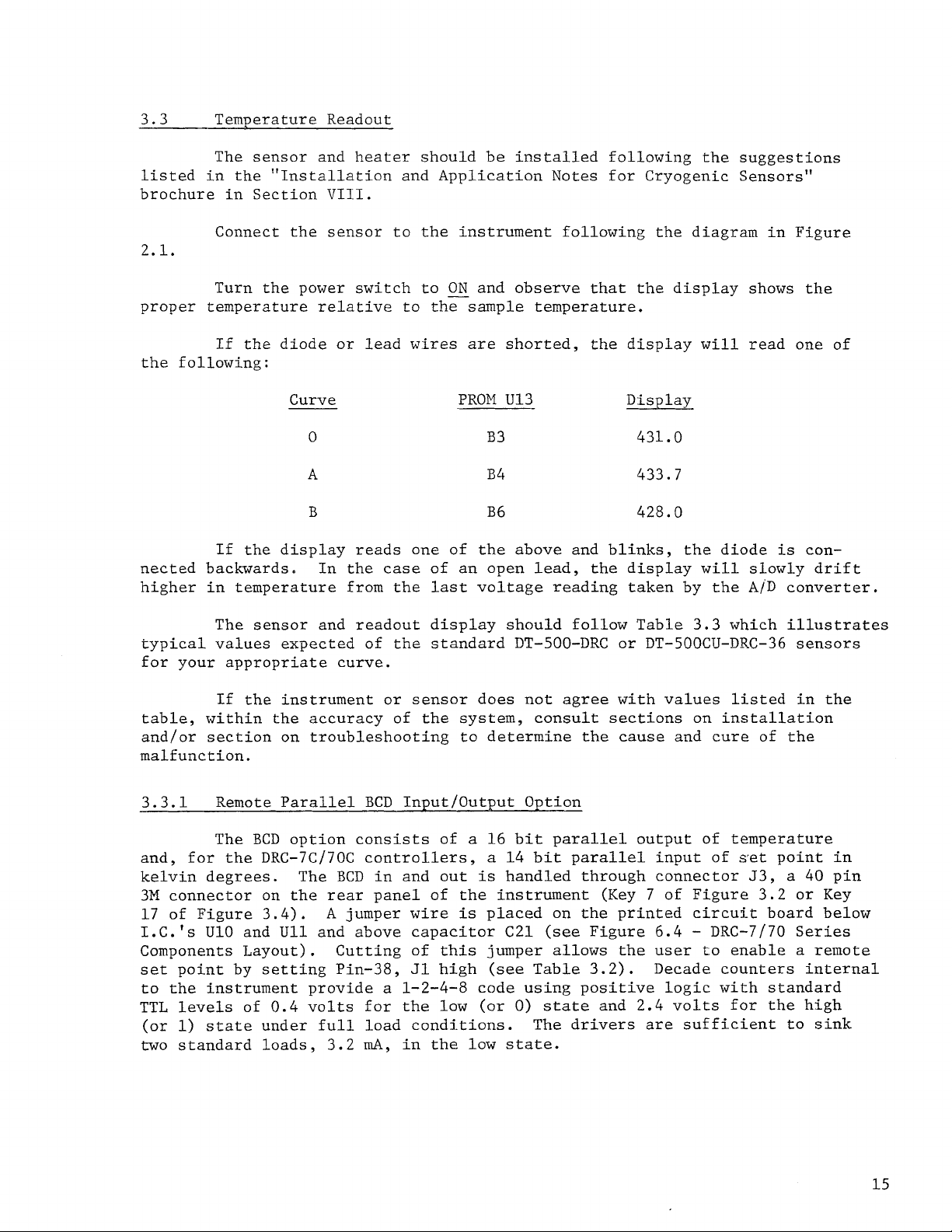
3.3 Temperature Readout
The sensor and heater should be installed following the suggestions
listed in the "Installation and Application Notes for Cryogenic Sensors"
brochure in Section
Connect the sensor to the instrument following the diagram in Figure
VIII.
2.1.
Turn the power switch to
proper temper
If
the following:
at
ur e re
the diode
Curve
0
la
t
ive to t he s amp
or
lead wires
A
B
If
the display reads one of the above and blinks, the diode
nected backwards.
higher in temperature from the
The sensor and readout display should follow Table 3.3 which illustrates
typical values expected of the standard DT-500-DRC
for your appropriate curve.
If the instrument or sensor does not agree with values listed in the
table, within the accuracy of the system, consult sections
and/or section
malfunction.
In
the case of an open lead, the display
on
troubleshooting to determine the cause and cure of the
ON
and observe that
1
e
temper a tur
are
shorted, the display
PROM
U13 Display
B3
B4
B6
last
voltage reading taken by the
the display shows the
e.
431.0
433.7
428.0
or
DT-500CU-DRC-36 sensors
will
will
on
read one
slowly drift
A/D
installation
of
is
con-
converter.
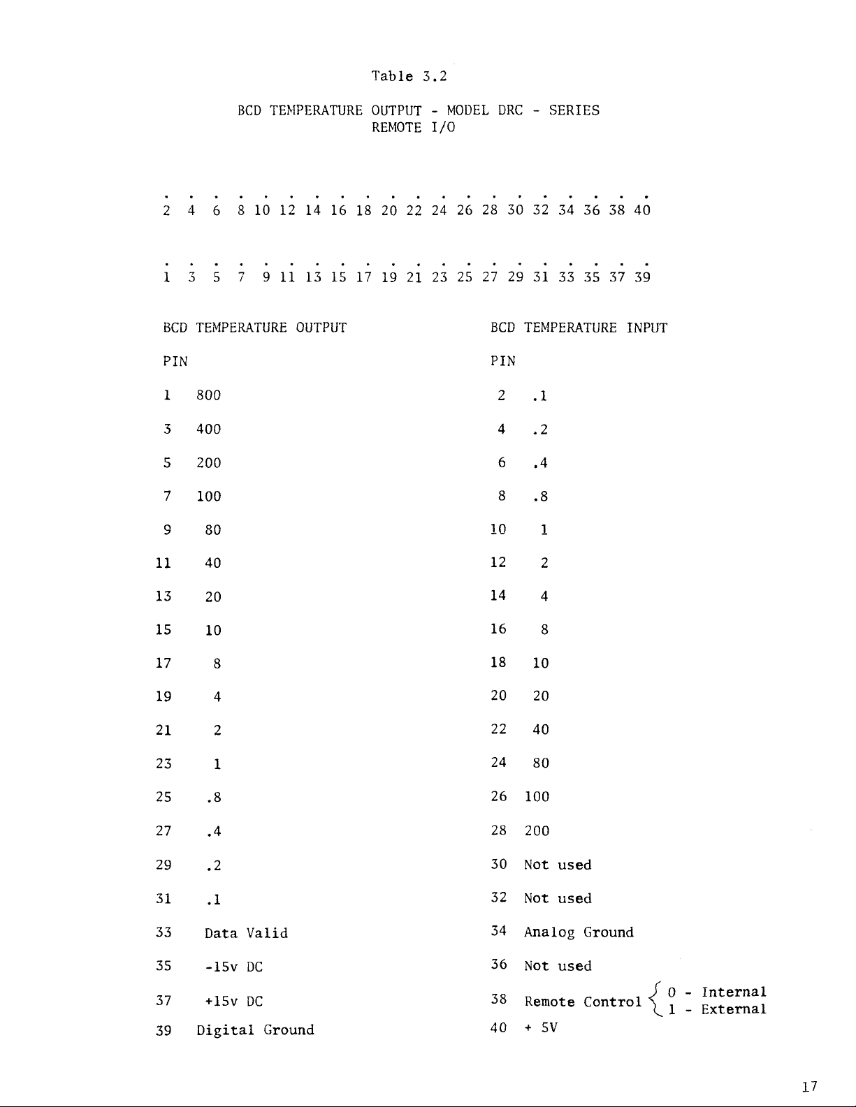
3.3.1 Remote Parallel
The
BCD
option consists of
and, for the DRC-7C/70C controllers,
kelvin degrees. The
3M connector on the
17
of Figure 3.4).
I.C.'s
Components Layout). Cutting of this jumper allows the user to enable
set
to the instrument provide
TTL
(or
two
U10 and
point by setting Pin-38,
levels of
1)
state
standard loads,
U11
and above capacitor C21 (see Figure
0.4
volts for the
under full load conditions.
BCD
rear
A
jumper
3.2
BCD
Input/Output Option
a
16
bit parallel output of temperature
a
14
bit
parallel
in and out
panel of the instrument (Key 7 of Figure 3.2 or Key
wire
J1
a
1-2-4-8 code using positive logic with standard
mA,
in the
is
handled through connector 53,
is
placed
high (see Table 3.2). Decade counters internal
low
(or
low
state.
on
the printed circuit board below
0)
state
The drivers are sufficient to sink
and 2.4 volts for the high
input of
6.4
-
DRC-7/70 Series
set
point in
a
40
a
pin
remote
3.4
Standard
DT-500-DRC
and
DT-500CU-DRC-36
Curves
The standard
Table
illustrates typical values expected of
The table also includes
in the linearization of the
readout.
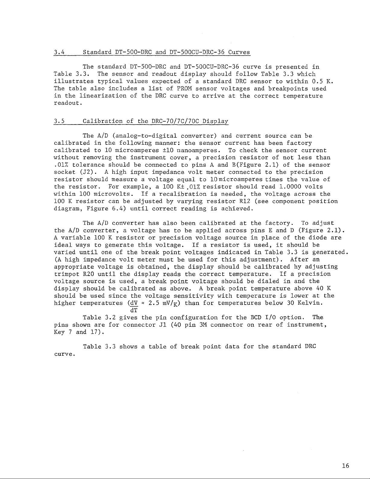
3.5 Calibration of the DRC-70/7C/70C Display
3.5
calibrated in the following manner: the sensor current has been factory
calibrated to
without removing the instrument cover,
.01%
socket
resistor should measure a voltage equal to 10microamperes
the resistor. For example,
within
100
diagram, Figure
the
A
ideal ways to generate this voltage. If a resistor
varied until one
(A high impedance volt
appropriate voltage
trimpot
voltage source
display should be calibrated
should be used since the voltage sensitivity with temperature
higher temperatures (dV
pins shown
Key
3.3.
tolerance should be connected to pins A and B(Figure
K
resistor can be adjusted by varying resistor
A/D
variable
7
and
The sensor and readout display should follow Table
The
A/D
10
(J2). A
100
microvolts. If a recalibration
The
converter,
R20
Table
high input impedance volt
A/D
100
K
until the display reads the correct temperature. If a precision
is
3.2
are
for connector
17).
DT-500-DRC
a
list
(analog-to-digital converter) and current source can be
microamperes
6.4)
until correct reading
converter has also been calibrated
a
voltage has to be applied across pins E and D (Figure
resistor or precision voltage source in place of the diode
of
the break point voltages indicated in Table
meter
is
obtained, the display should be calibrated hy adjusting
used, a break point voltage should be dialed in and the
=
2.5
dT
gives the pin configuration for the
and
of
DRC
±10
DT-500CU-DRC-36
a
standard
PROM
curve to
nanoamperes. To check the sensor current
sensor voltages and breakpoints used
arrive
a
precision resistor of not less than
curve
DRC
at
the correct temperature
is
sensor to within
2.1)
meter
a
100
K±,01%
must be used for this adjustment).
as
above.
mV/K)
J1
(40
pin
resistor should read
A
break point temperature above
than for temperatures below
3M
connected to the precision
times
is
needed, the voltage across the
R12
(see component position
is
achieved.
at
the factory.
is
used,
BCD
I/O
connector on
rear
presented in
3.3
which
of the sensor
the value of
1.0000
it
is
option.
of
volts
To adjust
should be
3.3
is
After
lower
30
Kelvin.
instrument,
0.5
K.
2.1).
are
generated.
an
40
K
at
the
The
curve.
Table
3.3
shows a table of break point data for the standard
DRC
2
4
6
1
3
5
BCD
TEMPERATURE
BCD
TEMPERATURE
8
10
12
14
7
9
11
13
OUTPUT
Table 3.2
OUTPUT
REMOTE
16 18 20 22
15
17 19
21
-
MODEL
DRC
-
SERIES
I/O
24
26 28 30 32 34 36 38 40
23 25 27 29 31 33 35 37 39
BCD
TEMPERATURE INPUT
PIN
1
800
3
400
5
200
7 100
9
80
11
13 20
15 10
17
19 4
21
23
40
8
2
1
PIN
2
.1
4
.2
6 .4
8
.8
10
12
14 4
16
18
20 20
22 40
24
1
2
8
10
80
25 .8
27 .4
29
31
33
35 -15V
37
39 Digital Ground
.2
.1
Data
+15v
Valid
DC
DC
26 100
28 200
30 Not used
32 Not used
34 Analog Ground
36
Not used
38 Remote Control
40
+
5V
0 - Internal
l
-
External
 Loading...