

Lakeshore 805 User Manual

User’s Manual
Model 805
Temperature Controller
This manual applies to instruments with Serial Numbers from 18000 and subsequent.
Obsolete Notice:
This manual describes an obsolete Lake Shore product. This manual is a copy from our archives
and may not exactly match your instrument. Lake Shore assumes no responsibility for this
manual matching your exact hardware revision or operational procedures. Lake Shore is not
responsible for any repairs made to the instrument based on information from this manual.
Methods and apparatus disclosed and described herein have been developed solely on company funds of Lake Shore Cryotronics, Inc.
No government or other contractual support or relationship whatsoever has existed which in any way affects or mitigates proprietary
rights of Lake Shore Cryotronics, Inc. in these developments. Methods and apparatus disclosed herein may be subject to U.S. Patents
existing or applied for. Lake Shore Cryotronics, Inc. reserves the right to add, improve, modify, or withdraw functions, design
modifications, or products at any time without notice. Lake Shore shall not be liable for errors contained herein or for incidental or
consequential damages in connection with furnishing, performance, or use of this material.
Obsolete Manual June 1987
Lake Shore Cryotronics, Inc.
575 McCorkle Blvd.
Westerville, Ohio 43082-8888 USA
Internet Addresses:
sales@lakeshore.com
service@lakeshore.com
Visit Our Website:
www.lakeshore.com
Fax: (614) 891-1392
Telephone: (614) 891-2243
TABLE
OF
CONTENTS
SECTION
1.1
1.2 DESCRIPTION
I
-
GENERAL INFORMATION
INTRODUCTION
1-1
1-1
1.3 INPUT OPTION MODULES 1-2
1-4 SPECIFICATIONS 1-4
SECTION
II
-
INSTALLATION
2.1 INTRODUCTION 2-1
2.2
2.3 PREPARATION FOR USE
INITIAL
INSPECTION 2-1
2.3.1 Power Requirements
2-3-2 Power Cord
2-1
2-1
2-1
2.3.3 Grounding Requirements 2-1
2.3.4 Bench Use 2-2
2.3-5 Rack Mounting 2-2
2.3.6 Sensor Input Connections 2-2
2-3-7 Sensor Output Monitors 2-3
2.3.8 SENSOR
ID
Switches 2-3
2.3.9 Heater Power 2-4
2-4 OPTIONS 2-4
2.4.1 Model
2.4.2 Model
8053 RS-232C Option 2-4
8054 IEEE-488 Option 2-4
2.4.3 Model 8055 Linear Analog Output Option 2-4
2.5
ENVIRONMENTAL
REQUIREMENTS 2-4
2.5.1 Operating Temperature 2-4
2.5-2 Humidity/Altitude 2-4
2.6
REPACKAGING FOR SHIPMENT 2-4
SECTION
III
-
3.1 INTRODUCTION
3.2 INSTRUMENT CONFIGURATION 3-1
3.2-1 Input Modules 3-1
3.3 PRECISION OPTIONS 3-1
3.4 CONTROL FUNDAMENTALS
3-5 CONTROLS
OPERATING INSTRUCTIONS
AND
INDICATORS 3-1
3-1
3-1
TABLE
FRONT PANEL DESCRIPTION
OF
CONTENTS. CONT'D
3.6
3.7
3-8
3-9
3.10
3.11
3.12
3.13
3-14
POWER ON/OFF Switch
3.6.1
DISPLAY SENSOR Block
3.7.1
3-7.2
3.7.3
3-7.4
CONTROL BLOCK
3.8.1
3-8.2
3.8-3
3-8-4
3.8-5
3.8-6
LOCAL/REMOTE OPERATION
CONTROL Switch
HEATER Power Output Terminals
SENSORS/MONITORS
SENSOR CURVE SELECTION
3.13.1 Display
3.13.2 The Precision Option Table
SENSOR ID Switches
POWER-UP Sequence
Display SENSOR
Units Select
Display
3.7.3.1
3.7.3.2
3.7.3.3
Filtering
CONTROL SENSOR
SET POINT
GAIN
RESET
HEATER
HEATER POWER Range
SENSOR
Voltage Units
Resistance Units
Temperature Units
the
%
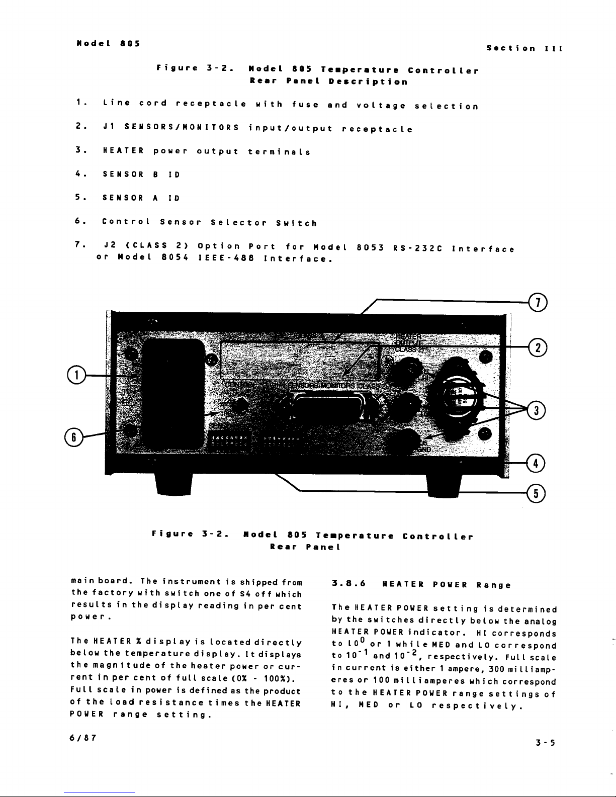
REAR PANEL DESCRIPTION
of
Accessed Curve
Input
Units
Display
3-1
3-1
3-2
3-2
3-2
3-2
3-2
3-2
3-2
3-2
3-4
3-4
3-4
3-4
3-4
3-4
3-5
3-6
3-6
3-6
3-6
3-6
3-7
3-7
3-7
SECTION IV . REMOTE OPERATION
4.1
4.2
4.3 INTERFACE CAPABILITIES
4.4
4.5
4-6
IEEE-488 INTERFACE (OPTION
GENERAL IEEE SPECIFICATIONS AND OPERATION
805
4.4.1
4.4.2
4-4-3
IEEE-488 BUS COMMANDS
4.5.1 Uniline Commands
4.5.2 Universal Commands
4.5.3
4.5.4 Unaddress Commands
4-5.5
4.5.6
PROGRAMMING INSTRUCTIONS
4.6-1
IEEE-488 ADDRESS SWITCH
Terminating Characters (delimiters)
Talker
The IEEE-488 INTERFACE
Addressed Commands
Device-Dependent Commands
Talker
Input
and/or
and
Data Format
8054)
Listener Configuration
Listener
bus
Status 4-5
and
Program Codes
address
4-1
4-1
4-1
4-2
4-2
4-2
4-2
4-2
4-2
4-3
4-3
4-3
4-3
4-5
4-5
TABLE
OF
CONTENTS.
CONT'D
4.7
4-8
4.9
4.10
4.11
4.12
4.13
INSTRUMENT SETUP PROGRAM CODES
4.7.1
4.7.2
4.7.3
4-7-4
SELECTION OFSETPOINTUNITSANDDISPLAYSENSOR (Table 4-4)
4.8.1
4.8-2
The
THE CONTROL COMMANDS (See Table
4.10.1 The Set Point Value
4.10.2
4-10.3 Setting
4.10.4 Heater Range . The R Command
4-10.5
Output Statement
PROGRAM EXAMPLES
4.12.1
Sample Programming 4-11
4.13.1 HP86B Keyboard
4.13.2 National Instruments IBM Example
4-13.3 HP Example
EOI Status . The ZN1 Command
Interface
4-7.2.1
4.7-2.2
4.7-2.3
Terminating
Clear
Units
Display Sensor Selection . The F1C1 Command 4-6
A
and
B
Setting
Note: The Return
Output
4.12.1.1 The
4.12.1.2 The "W1" Data String (Table
4-12.1.3 The
4.12.1.4 The "W3" Data String Table
4.12.1.5 The
4.12-1.6 The "WI" Data String (Table
for
SENSOR ID Information . The AC1C2
Mode
Local 4-6
Remote
Local
Set Point . The FOC1 Command 4-6
the
the
Data Statements
of
.
The
Lockout
characters
GAIN
RESET
Request
"W0"
"W2"
"WS"
.
Data String (Table 4-7) 4-10
Data String (Table
and
Interactive
805 Commands
MN1
.
The S Command
The P Command
(Integral)
to
Local
.
The WC1 Command
"WP"
Command
.
The TN1 Command
Data Strings (Table
(see
4-5)
Program
Table
and
.
The I Command
4-4)
BC1C2 Commands
4-7)
4-7)
4-7)
4-84-11
4-8)
4-6
4-6
4-6
4-6
4-6
4-6
4-6
4-6
4-6
4-9
4-9
4-9
4-9
4-9
4-9
4-9
4-9
4-10
4-10
4-10
4-11
4-11
4-11
4-11
4-13
SECTION V
5.1
5.2
5.3
5.4
5.5
5.6
5.7 TROUBLESHOOTING 5-2
SECTION VI
6.1
6.2
6-3
6-4
6-5 OPTION INTERFACE CARDS
INTRODUCTION 5-1
GENERAL MAINTENANCE 5-1
FUSE REPLACEMENT
LINE VOLTAGE SELECTION 5-1
PERFORMANCE VERIFICATION
5.5.1
5.5.2 Performance Verification Procedure
CALIBRATION
INTRODUCTION
OPTION INPUT MODULES
ACCESSORIES
OUTPUT POWER OPTION
.
MAINTENANCE
Performance Verification Connector
.
OPTION
AND
5-1
5-1
5-2
5-2
5-2
ACCESSORY INFORMATION
6-1
6-1
6-1
6-2
6-2
LIST
OF
TABLES
AND
ILLUSTRATIONS
SECTION
Table
Table 1-2. Specifications, Model 805 Temperature Controller 1-4
SECTION
Table 2-1-Line Voltage Selection 2-1
Figure
Table 2-2-Connector Plug Connections 2-2
Figure
Figure
Table 2-3, SENSOR
SECTION
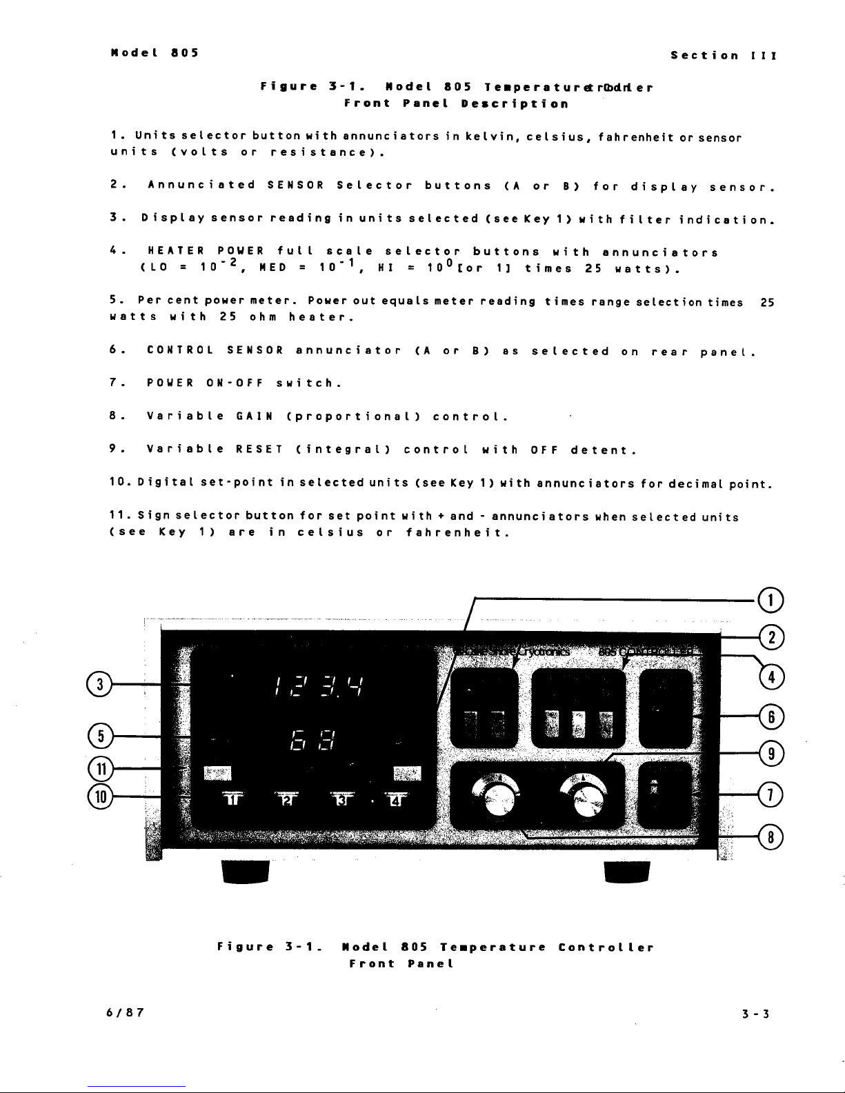
Figure 3-1.
Table 3-1-Reset Settings. 3-4
Figure
Figure 3-3a. Nominal Gain Settings 3-6
Figure 3-3b. Nominal Reset Settings (Beats/Second) 3-6
Table 3-2.
Table 3-3. Sensor Curve Table Information
Figure 3-4, SENSOR
I
-
GENERAL
1-1.
Input
I1 - INSTALLATION
2-1,
Typical Rack Configuration
2-2. Sensor
2-3. Sensor
III
Model
3-2. Model
Standard
Option Modules, Model
Connections 2-3
IO
ID
-
OPERATING
805 Temperature Controller - Front Panel 3-3
805 Temperature Controller - Rear Panel 3-5
Curve Information 3-6
ID
INFORMATION
805
Temperature Controller 1-3
2-2
Definitions 2-3
Curve Address 2-4
INSTRUCTIONS
-
PrecisionOptionTable 3-7
Definitions. 3-8
SECTION
Table 4-1. Interface Functions.. 4-2
Figure 4-1. IEEE-488 Address Switch for the 805. 4-3
Table 4-2.
Table 4-3. IEEE-488 Bus Commands. 4-5
Table 4-4. 805 Listener Program Code Summary
Table 4-5. 805 Program Code Summary, Cont'd.
Table 4-6.
Table 4-7. 805
Table 4-8.805
SECTION
SECTION
Table 6-1. Option and Accesories for Model805 Temperature Controller.. 6-1
IV
-
REMOTE
Allowable
of Set Point Units, Display Sensor and Setting
Control Commands and Output Statement Request. 4-8
Remote
Output
Output
V
-
MAINTENANCE
VI - OPTION
OPERATION
Address Codes for the 805 4-4
-
Instrument Setup, Selection
Interface Input of the A and
Talker Data Statements. 4-12
Talker Data Statements. 4-13
AND
ACCESSORY
INFORMATION
SENSOR
B
SENSOR
ID.
ID.
4-7
4-9
SECTION
I
GENERAL INFORMATION
1-1
The information contained
manual is for the installation, operation,
remote programming and option and accessory information for
Cryotronics, Inc.
Controller.
Guide is available for this instrument which
contains performance and calibration
procedures, schematics, component layouts
and a replaceable parts list.
This section contains general information for
the Lake Shore Cryotronics, Inc.
Temperature Controller. Included is an
instrument description, specifications,
instrument identification, option and
accessory information.
1.2
The 805 Temperature Controller is a
microprocessor based instrument which
providestrueanalog control.
inputs from
the temperature with up to 4 digits of
resolution
voltage for diodes to 1
for resistors to four places.
The dual sensor
monitor temperature at more than one point.
Sensor select pushbuttons on the front panel
enable the user to display either input at
will.
via a rear-panel toggle switch with the
choice indicated on the front panel. This
choice is independent of display status.
The Model 805 is direct reading
ture when used with the Lake Shore DT-470
Series Temperature Sensors.
Sensors follow the same temperature
response curve. Four bands of tracking
accuracy are offered so that sensor selection
may be made with both technical and
economical considerations for any given
application. Low temperature (2 to
INTRODUCTION
in
this operations
the
Lake Shore
Model
A
separate Technical Service
805 Temperature
805
DESCRIPTION
It
accepts
up
to two sensors and displays
in
K,
°C or
input
The system control sensor is selected
°F.
It
displays
millivolt,
allowstheuser to
and ohms
in
tempera-
All
DT-470
100K)
accuracies range from 0.25K for band
1K for band 13. For more demanding
requirements, DT-470 Sensors can be individually calibrated to accuracies of better
50
than
ture range.
Diode sensor voltages are digitized with a
resolution of
full scale. For the display, temperature is
rounded to
to
For greater precision individual sensor
calibrations can be accommodated through
the 8001 Precision Calibration Option which
programs the instrument with a particular
response curve. The algorithm within the
instrument interpolates between data points
to an interpolation accuracy which exceeds
0.01K over the entire temperature range of
the Precision Option. The analog-to-digital
converter is accurate to plus or minus the
least significant bit, which forthe470
series sensor results
1mK
transitional region between the two
temperatures. Therefore, at temperatures
below 28K, the overall system accuracy, the
sum
that of the calibration itself (Lake
calibrations are typically better than 20mK
within this region) is ±0.03K. Above 28K,
system
typical value of ±75mK above 40K. Seethe
Lake Shore Cryotronics, Inc. Low
ture Calibration Service brochure for
additional discussion of calibration accuracy.
The 805 display uses digital filtering which
averages up to ten temperature readings.
This reading mode eliminates noise within
the cryogenic system analogous to averaging
with a digital voltmeter. This algorithm
can be deselected (bypassed) by switch 2
the
panel for a given
not to average readings. A blinking
decimal point at the upper left of the
millikelvin depending on tempera-
100
microvolts out of 3 volts
0.1
kelvin above
0.01
below 28K and 45mK above 40K with a
of
SENSOR
kelvin below
the instrument accuracy
accuracy
gradually moderates to
ID
dip switch on the back
input
100
kelvin, and
100
in
an uncertainty of
if
the user prefers
11
kelvin.
(11mK)
and
Shore
Tempera-
to
a
of
1-1
display indicates that averaging is on.
The Model805 can also be used with the
optional input conversion modules (-6) which
allow either input to be converted to handle
either the TG-120 series diodes
(or any
diode with a 0 to 6 volt output), or positive
temperature coefficient metallic resistors.,
i.e., platinum (-P2 or -P3) or rhodium-iron
(-R1)
within the instrument and is called
resistors. The
DIN
curve isstandard
up
automatically unless a precisionoption is
present for the platinum resistor. The
of
accuracy
sensor and its conformity
the reading is dictated by the
to the
DIN curve.
The tolerance on these devices is given on
the technical data sheet for the Lake Shore
PT-100 series sensors. Thecombined
accuracy of the instrument and a calibrated
resistor with a precision option is on the
order of 40mK over the useful range ofthe
sensor (above 40K for the platinum). Note
that a precision option is required for a
rhodium-iron or a TG-120 to readcorrectly
in
temperature.
These
input
conversionmodules are easily
instal led by the user; thus, units can be
modified to satisfy changing requirements.
in
The ample memory space provided
the805
allows several response curves to be stored
in
one instrument. Depending on the
complexity of the curves, up toten can be
programmed into the unit. The
SENSOR
ID
switches are used to select which particular
sensor response curve is to be used with
input.
each
sensor changes at
Thus, the user is able to make
will
even when different
response curves are required.
The data for calibrated sensors can be
stored within the instrument by means of
the8001 Precision Option. Each curve can
99
contain up to
sensor unit-temperature
data points. With the standard precision
option format, which consists of 31 data
points and a 20 character information line,
in
the
up toten curves can be stored
unit.
See Paragraphs 3-6 through 3-10 for more
description.
A1 though voltage (resistance)-temperature
data points arestored as a table, interpola-
in
tion within the instrument results
the
equivalent of a high order polynomial
in
calculation
the converting ofthe input
voltage (or resistance) to temperature.
This is done by means of a proprietary
algorithm developed at Lake Shore Cryotronics, Inc.
T
h e control temperature set - poi
n
t
selection
is made via thumbwheel switches on the
front panel ofthe instrument. The setpoint switches, which provide a continuous
indication of the set-point value, enable the
user to quickly and easily determine
whether his system is at control temperature. The set-point is in the same units as
is the Display sensor (kelvin, celsius,
fahrenheit, or volts [ohms]).
The control sectionof the805 provides
two- term temperature control. Proportional
(GAIN)
and integral
(RESET)
are individually tuned via front-panel potentiometers.
The gain mode is in a nominal log per cent
with the reset being linear.
the
Analog heater output of
ture Controller is a maximum of
805 Tempera-
25
watts
when a 25 ohmheater is used. A digital
meter on the front panel of the 805
continuously shows the heater power output
as a percentage of output range. Thus, the
user can conveniently monitor power applied
to his system. To accommodate systems
which require lower heater power, the
maximum heater output of the805 can be
of
attenuated in two steps
When greater power output is required,
a decade each.
an
optional 56 watt power output stage is
for
available (W60) which is designed
It
ohm load.
is rated at a nominal
a 25
1.5
amperes and 45 volts.
An optional IEEE-488 (Model
8054)
or
RS-
232C (Model 8053) interface is available for
the 805. Either interfacecan be used to
remotely control all front-panel functions.
1.3
INPUT OPTION
MODULES
1-2
The input option modules forthe805
Controller are listed
in
Table
1.1.
Table
1.1.
Input
Option
Modules,
Model
805
Temperature Controller
Diode or Resistance Sensor
(ordered separately):
DIODE SENSOR CONFIGURATION
Diode Excitation:
microamperes
current source less than 0.01%
DC
(±0.005%).
current Source. 10
AC
noise from
of DC
current.
Diode
Voltage Range:
0
to 3 volts
in
standard configuration.
Diode Temperature Range: Dependent on
Sensor selected. DT-470-SD covers tempera-
1.4
ture range from
to475 kelvin. Refer to
diode specifications for other temperature
limitations.
Diode Response Curve(s): The silicon diode
series DT-470 Curve #10 as well as the
series DT-500
DRC-D
present in the 805. Curves
and DRC-E curves are
to
match other
existing Sensors are available on request.
Diode Sensor Power Dissipation: Dissipation
is the product of Sensor Excitation Current
uA)
10
Accuracy:
accuracy
and Resultant Sensor Voltage.
Unit
reads sensor voltage to
of
better than 0.1mV. Equivalent
an
temperature accuracy is a function of Sensor
type, temperature (sensitivity) and calibration of Sensor. Seethe Technical Data
Sheet for the DT-470 Series Temperature
Sensors and the Model 8001 Precision Option
LSCI
for accuracy with
calibrated sensors.
6-VOLT DIODE SENSOR MODULE
-6
Diode Sensor
standardconfiguration but has 0
input
to accommodate TG-120 Series Sensors.
Converts either Input A or Input
Input
Module, Similar to
to
6 volt
6
(or both
with two modules) to accommodate the 6
volt modification for TG-120 series sensors.
Requires calibrated sensor and 8001 Precision
Option for 805 to be direct reading in
temperature. This modulemay be field
installed.
OHM
100
-P2 100 Ohm
PLATINUM MODULE
Platinum
Sensor Module:
Converts either Input A or
6 (or both with
two modules) to accommodate 100 ohm
Platinum RTD Sensors. This modulemay be
field installed.
t
Tempera
range depends on Sensor. Resistance
one range from
ure/Resistance Range: Temperature
in
000.0
to 300.0 ohms.
Resolution: 0.01 ohm or equivalent
temperature.
Sensor (order separately): Configuration
PT100
optimized for
or any other100 ohm (at
Series Platinum Sensors
0°C)
positive
temperature coefficient Sensor.
Sensor Excitation:
Sensor Response
response curve is based on 0.1
changeability
coefficient
Accuracy
conforms
at
(0-100°C)
1
.0
mA
(±0.005%).
Curve:
0°C
Platinum Sensor
%
inter-
and temperature
of 0.00385/°C.
to DIN 43760 tolerances
plus display (electronics). Special calibrations can be accommodated with 8001
Precision Option.
Sensor Power Dissipation: Dissipation is
the product of sensor excitation current
squared and the Sensor resistance.
OHM
1000
-P3 1000 Ohm
PLATINUM MODULE
Platinum Sensor
Module:
Essentially the same as the -P2 except
1000
accommodates
ohm Platinum Sensor (or
any other 1000 ohmmetallic sensor).
Sensor excitation is 0.1 milliampere.
Unit
reads resistance in ohms. Requires
calibrated sensor and programmed calibration to read temperature. Accuracy is
0.1
ohm or equivalent temperature.
27
OHM
RHODIUM-IRON MODULE
-R1 27-ohm Rhodium-Iron Sensor Module:
Essentially the same as -P2 except accommodates RF-800-4 Rhodium-Ironsensor.
Sensor excitation is 1mA. Unit reads
in
resistance
ohms. Requires calibrated
sensor, etc. to read temperature. Accuracy
and resolution is 0.003 ohms or equivalent
temperature.
1-3
1.4
Instrument specifications are listed in Table
1.2. These specifications are the perfor-
mance standards
instrument is tested.
Option ports aredesigned into the805 to
ease the addition of interfaces and outputs.
The Model 805 has two option ports which
allow
simultaneously (see limitations below). The
options are easily installed by the user; thus,
units can be changed
SPECIFICATIONS
or
limits
up
to two options to be used
against which the
or upgraded to satisfy changing requirements.
Only one computer interface can be
installed in the805 due to space limitations
in
the805 rear-panel. The Model
Analog Output option is available to provide
an analog output of 1mV/K
thedisplay temperature units.
display is in sensor units, theoutput for
diodes is
1mV/ohm; for
0.1mV/ohm; for rhodium-iron, 10mv/ohm.
0.1V/V;
for 100 ohm platinum,
1000
independent of
ohm platinum,
8055
If
the
Table
INPUT CHARACTERISTICS:
Inputs:
(A
or
B)
indicated on the front panel. Display sensor
(A
or
B)
interface, independent of control sensor.
input
The
Sensor Input Module Installed. The805 can
accommodate separate
A
and
B
of different sensor types.
Input
configuration for the805 is
up to use DT-470 series silicon diode sensors
(0-3V). Optional input conversionmodules
allow
diode sensors (0-6V), as well as PT-100
series 100/1000 ohm platinum RTD's, and
800 series rhodium-iron sensors.
Input Conversion Module
the
(one per input)
1.2.
Two Sensor Inputs. Control Sensor
selected via rear panel switchand
can be selected from front panel or
characteristics are a function of
input.
Conversion Modules: Standard
805 to be used with TG-120 series
-6*
-P2
-P3*
-R1* 27 ohm rhodium-iron
Specifications, Model
input
This allows concurrent use
100
1000
modules for
both
inputs set
S
en
s
o
r
6
volt diodes
(e.g. TG-120)
ohm Platinum
ohm Platinum
the
RF-
Type
805
Temperature
rhodium-iron RTD's and other positive
temperature coefficient resistors with
proper choice of input. Seethe Lakeshore
Cryotronics, Inc. Sensor catalog for details
on the above Sensors.
Sensor Response Selection: Rear-panel Dip
switch or Interface permits selection of
appropriate Sensor response curve when
more than one curve is stored (see
Precision Option).
DISPLAY READOUT:
Display:
reading in
temperature
annunciators.
Display Resolution: 0.1K above
below 100K, or 1
tance option)
Temperature Accuracy: Dependent on
Sensor Input and Sensor. See Input
Options available.
Temperature Range: Dependent on Sensor
Input
4-digit
Sensor
in
K,
Module and Sensor.
Controller
LED
Display of Sensor
Units (Volts or Ohms) or
°C,
or
°F
shown with
100K,
0.01K
mV
(0.1 ohm
with
resis-
*To readcorrectly in a
scale,
calibrated sensors and the 8001 Precision
option for the 805.
Sensors: Ordered Separately. 805 with
input
types of diodes as well as platinum and
1-4
these modules
conversionmoduleswill handle
temperature
require the use of
all

Table
1-2.
Specifications, Model
805
-
Continued
TEMPERATURE
Set Point:
CONTROL:
Digital thumbwheel selection
in
kelvin, celsius, fahrenheit, or volts (ohms
with
Set Point Resolution:
resistance option).
Same units and
resolution as display.
Controllability:
Typically better than 0.1K
in
a properly designed system.
Control Modes:
Proportional (gain) and
integral (reset) set via front-panel or with
optional computer interface.
Heater output:
Up to 25 watts (1A, 25V)
available. Three output ranges can be
selected either from
optional computer interface and provide approximate decade step reductions of maximum
power output. Optional 60 watt, 1.5 ampere
25
ohm output (Option W60)
is
available for
the 805.
GENERAL:
Sensor Voltage/Monitor:
Buffered output of
each diode sensor voltage for standard
configuration. For -6 optionmodule,
voltage output times 0.5. For positive
temperature coefficient modules (-P2, -P3,-
R1),
buffer is sensor voltage output times-
10.
Response time (electronics):
Display update
cycle time of less than1 second (650 msec
2
typical).
seconds (3 readings) on channel
change or step change.
IEEE-488 Interfaceoption:
Allows remote
control of setpoint, gain, reset, units,
display sensor and heater power range
(except power on/off). Provides output of
display, display units and all front panel
functions.
RS-232C Interfaceoption:
Controls same
parameters as IEEE-488 Interface.
Heater output
Monitor: LED display
continuously shows heater output as a
percentage of output range with a resolution
1%.
of
Control Sensor:
Either Sensor
Input
(selected from rear panel).
Dimensions, Weight:
x
high
381 mm deep (8.5 in. x 4 in. x 15
216 mm wide x 102 mm
in.),
5.5 kilograms (12 pounds).
Power:
100,
120, 220 or 240
VAC
(selected
via rear panel with instrument off), 50 or
Hz,
60
Accessories Supplied:
75 watts.
Mating connector for
sensor/monitor connector, operations
manual.
1-5

This Page Intentionally
Left
Blank
SECTION
II
INSTALLATION
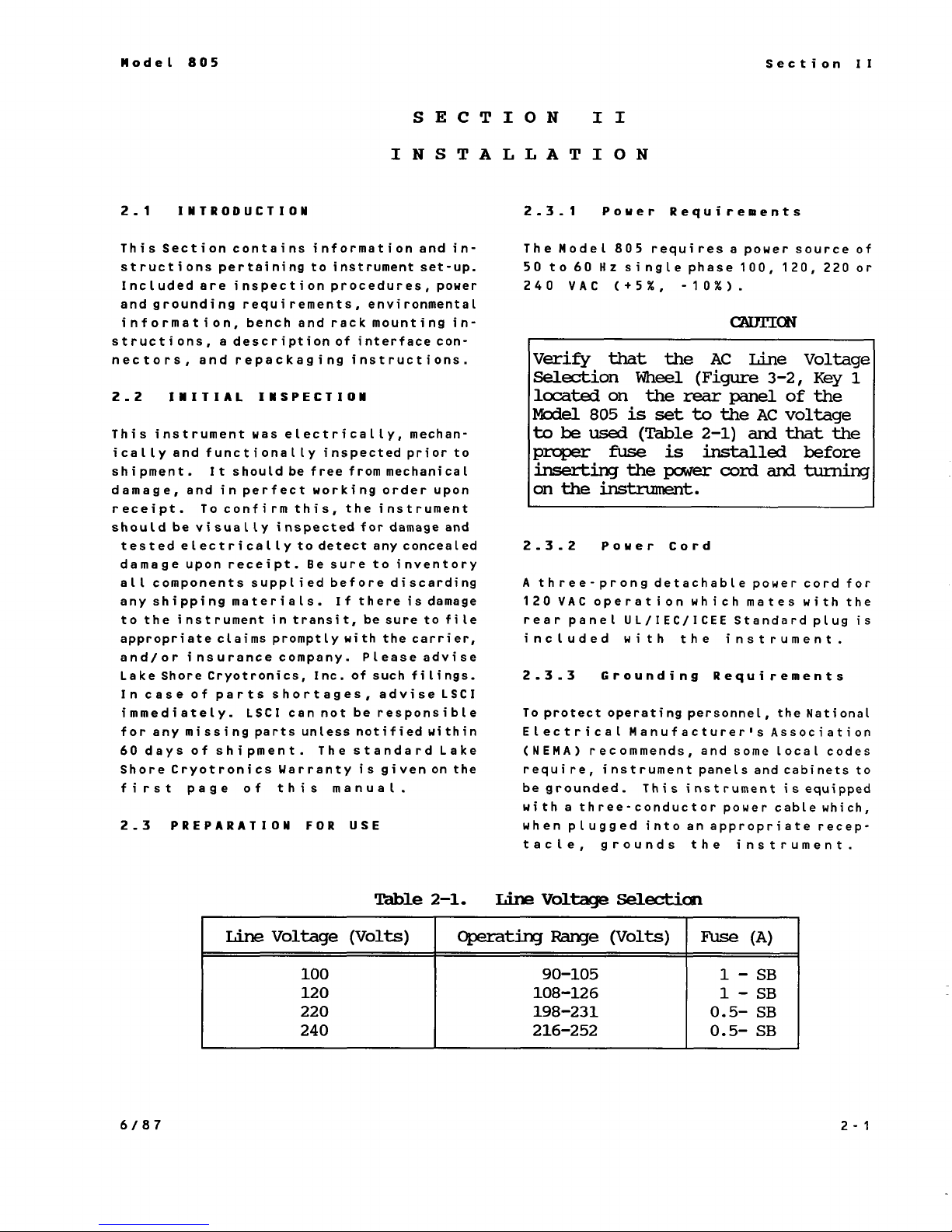
2.1
This Section contains information and
structions pertaining to instrument set-up.
Included are inspection procedures, power
and grounding requirements, environmental
information, bench and rack mounting instructions, a description of interface connectors, and repackaging instructions.
2.2
This instrument was electrically, mechan-
ically and functionally inspected prior to
shipment.
damage, and
receipt. To confirm this, the instrument
should be visually inspected for damage and
tested electrically to detect any concealed
damage upon receipt. Be sure to inventory
all components supplied before discarding
any shipping materials.
to the instrument
appropriate claims promptly with the carrier,
and/or insurance company. Pleaseadvise
Lake Shore Cryotronics, Inc. of such filings.
In case of parts shortages, advise LSCI
immediately.
for any missing parts unless notified within
60
Shore Cryotronics Warranty is given
first page
2.3
INTRODUCTION
in-
INITIAL INSPECTION
It
should be free from mechanical
in
perfect working order upon
If
there is damage
in
transit, be sure to file
LSCI
cannot be responsible
days of shipment. The standard Lake
on
the
of
this manual.
PREPARATION
FOR
USE
2.3.1
The Model
50 to
240
Verify
Selection
located
Model
to
proper
inserting
on
2.3.2
A
three-prong detachable
120
rear panel
included with the instrument.
2.3.3 Grounding Requirements
To protect operating personnel, the National
Electrical Manufacturer's Association
(NEMA)
require, instrument panels and cabinets to
be grounded. This instrument
with a three-conductor power cable which,
when plugged into an appropriate receptacle, grounds the instrument.
Power Requirements
805
requires a power source
60
Hz
single phase 100, 120, 220 or
VAC
be
the
VAC
(+5%,
that
on
805
used
fuse
is
the
-10%).
the
Wheel
the
rear
set
(Table
is
power
CAUTION
AC
Line
(Figure
3-2,
panel
to
the
AC
2-1)
and
installed
cord
and
Voltage
of
voltage
that
before
turning
instrument.
Power Cord
power cord for
operation which mates with the
UL/IEC/ICEE
recommends, and some local codes
Standard plug
is
of
Key
1
the
the
is
equipped
Line
Voltage
100
120
220
240
Table
(Volts)
2-1.
Operating
Line
Voltage
Range
90-105
108-126
198-231
216-252
Selection
(Volts)
Fuse
0.5-
0.5-
1
1
-
-
(A)
SB
SB
SB
SB
2-1
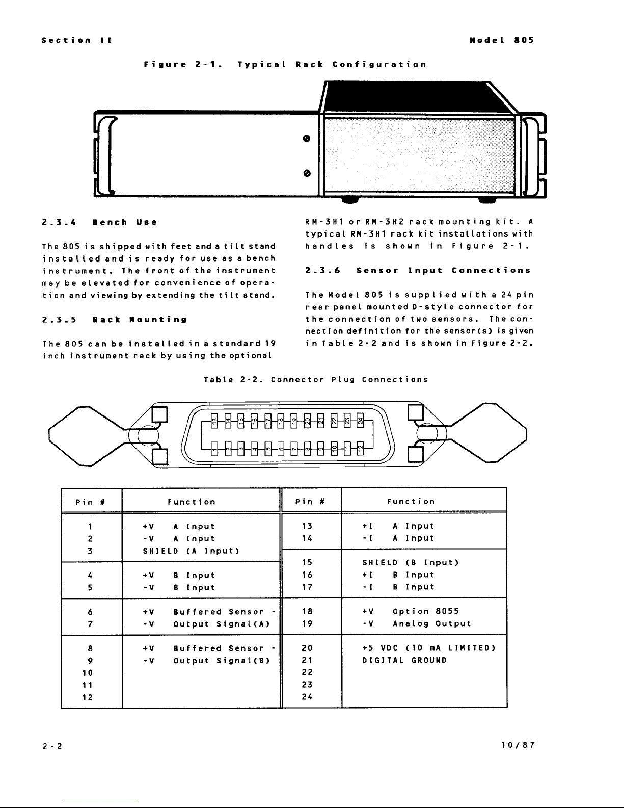
Figure
2-1,
Typical Rack Configuration
2.3.4
Bench Use
The 805 is shipped with feet and a
tilt
stand
installed and is ready for use as a bench
instrument. The front of the instrument
may be elevated for convenienceof opera-
tion and viewing
by
extending the
tilt
stand.
2.3.5
Rack Mounting
The 805 can be installed
in
a standard
19
inch instrument rack
by
using theoptional
RM-3H1 or RM-3H2 rack mounting kit.
A
typical RM-3H1 rack kit installations with
handles is shown
in
Figure 2-1.
2.3-6
Sensor Input Connections
The Model 805 is supplied with a 24 pin
rear panel mounted D-style connector for
the connection of two sensors. The connection definition for the sensor(s) is given
in
Table 2-2 and is shown
in
Figure 2-2.
Table 2-2. Connector Plug Connections
Pin
#
1
2
3
4
5
6
7
8
9
10
11
12
Function
+V
A
Input
-V
A
Input
SHIELD
(A
Input)
+V
B
Input
-V
B
Input
+V Buffered Sensor
-V
Output
Signal(A)
+V
Buffered Sensor
-
-V
Output
Signal(B)
Pin
#
13
14
15
16
17
18
19
20
21
22
23
24
Function
+I
A
Input
-I
A
Input
SHIELD
(B
Input)
+I
B
Input
-I
B
Input
+V
Option
8055
-V
Analog
Output
+5
VDC
(10
mA
LIMITED)
DIGITAL GROUND
2-2
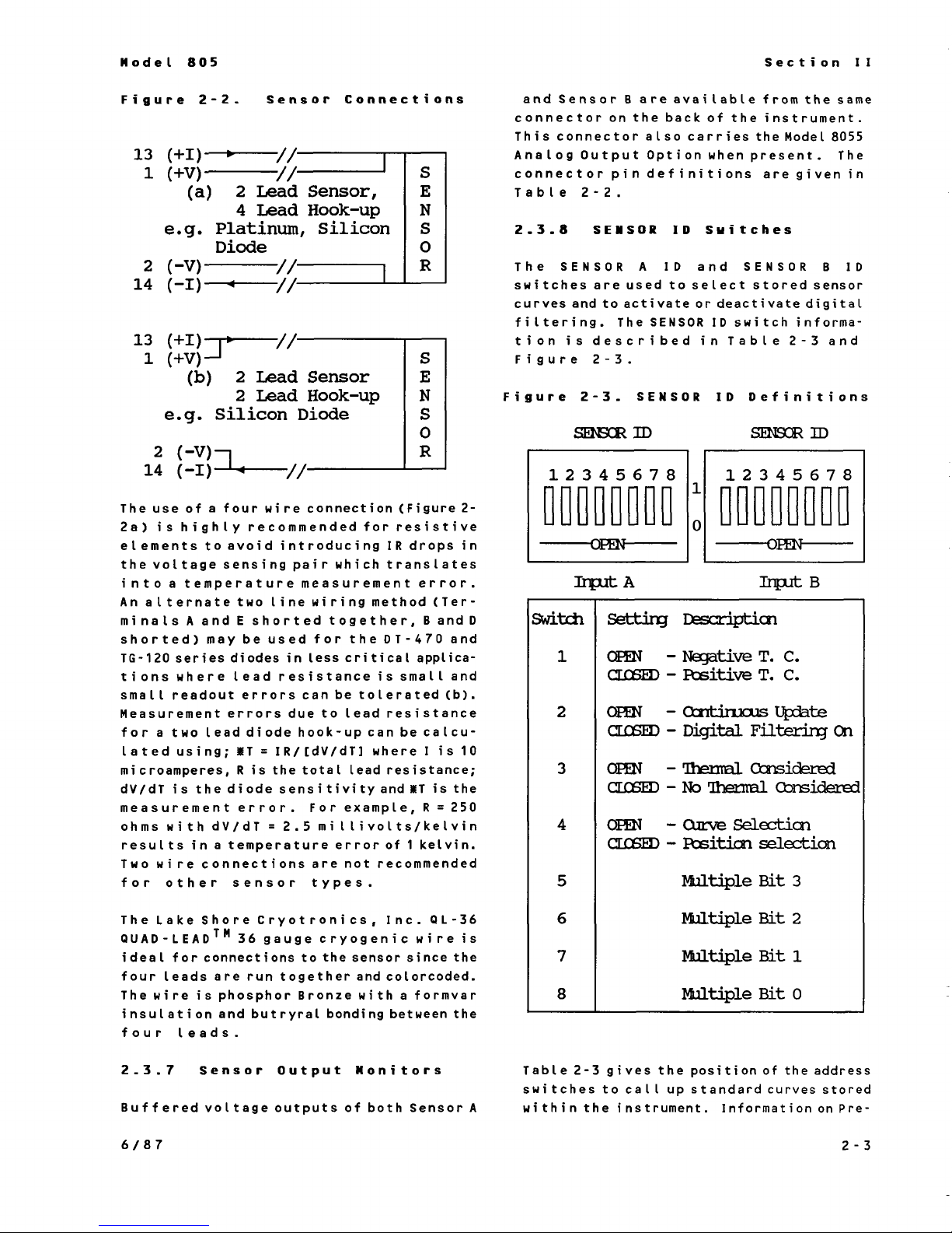
Figure
2-2,
Sensor Connections
and Sensor
connector on the back of the instrument.
This connector also carries the Model
Analog Output Option when present. The
connector
Table 2-2.
6
areavailable from
pin
definitions are given in
the
8055
same
The use of a four wire connection (Figure 2-
for
2a) is highly recommended
elements
the voltage sensing pair which translates
into a temperature
An
alternate two line wiring method (Ter-
minals
shorted)
TG-120 series
tions where lead resistance is small and
small readout errors can betolerated (b).
Measurement errors due to lead resistance
for a two leaddiode hook-upcan be
lated using;
microamperes,
dV/dT is the diode sensitivity
measurement error. For example,
ohms with dV/dT = 2.5 millivolts/kelvin
results
Two wire connections are not recommended
for other sensor types.
to avoid
A
and E shorted together, B and
may
diodes
in
a temperature error
introducing
measurement
be used for the
in
less critical applica-
T
=
IR/[dV/dT] where I is 10
R
is the total lead resistance;
resistive
IR
drops
error.
DT-470
calcu-
and
T
is the
R = 250
of
1
kelvin.
in
D
and
2.3.8
The
switches are
curves and to activate or deactivatedigital
filtering. The
tion is described
Figure 2-3.
Figure
Switch
SENSOR
SENSOR
used
2-3.
setting
1
2
3
OPEN
CLOSED
OPEN
CLOSED
OPEN
ID
Switches
A ID
SENSOR
SENSOR
and
to select stored sensor
SENSOR
ID
switch informa-
in
Table 2-3 and
ID
Definitions
Description
- Negative T.
-
Positive
- Continuous
-
DigitaI.
C.
T.
C.
Update
Filtering
- Thermal Considered
B
On
CLOSED - No Thermal Considered
4
5
OPEN
CLOSED
- Curve Selection
-
Position
Multiple
selection
Bit
3
ID
The Lake Shore Cryotronics, Inc.
QUAD-LEAD™
ideal for connections to the sensor since the
four leads are
The wire is phosphor Bronze with a formvar
insulation and butryral bonding between the
four leads.
2.3.7
Buffered
36 gauge cryogenic wire is
run
together and color coded.
Sensor
voltage
Output
outputs of both Sensor A
QL-36
Monitors
6
7
8
Table 2-3 gives the position of the address
switches to call up standard curves stored
within the instrument. Information on Pre-
Multiple
Multiple
Multiple
Bit
Bit
Bit
2
1
o
2-3
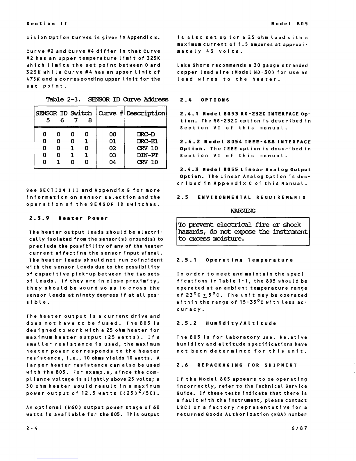
cision Option Curves is given
Curve
#2
which limits the set point betueen
325K while Curve #4 has an upper
475K and a corresponding upper
set point.
#2
and Curve
has an upper temperature limit of
#4
differ
in
Appendix
in
that Curve
limit
B.
325K
0 and
limit
of
for the
is
also
maximum current of 1.5 amperes at approximately 43 volts.
Lake Shore recommends a 30 gauge stranded
copper lead wire
lead wires to the heater.
set
up
for a 25 ohm load with a
(Model ND-30)
for use as
Table
SENSOR
5 6 7 8
0 0 0 0
0 0 0 1
0 0 1 0
0 0 1 1
0 1 0 0
See
SECTION
information on sensor selectionand the
operationof the SENSOR ID switches.
2.3.9
The heater output leads should be electrically isolated from the sensor(s) ground(s) to
preclude the possibility of any of the heater
current affecting the sensor
The heater leads shouldnot runcoincident
with the sensor leads due to the possibility
of
capacitive pick-up betueen the two sets
of
leads.
they should be wound
sensor leads at ninety degrees
sible.
The heater output is a current drive and
does not have to be fused. The 805 is
designed to work with a
maximumheater output
smaller resistance is used, themaximum
heater power corresponds to the heater
resistance, i.e., 10 ohms yields
larger heater resistance can also be used
with the 805. For example, since the compliance voltage is slightly above
50
ohmheater would result in a maximum
power output of
Anoptional
watts is available for the 805. This output
2-3.
ID
Switch
III and Appendix B for more
Heater
If
they are in close proximity,
(W60)
SENSOR
Power
12.5
output power stage of 60
ID
Curve
Curve
so as to cross the
watts
#
Description
I
00
01
02
03
04
25
ohmheater for
(25
watts). If a
DRC-D
DRC-E1
CRV
DIN-PT
CRV
input
if
at all pos-
10
watts.
25
volts; a
[(25)
2
Address
10
10
signal.
A
/50].
2-4 OPTIONS
2.4.1 Model 8053
tion. The
Section
2.4.2 Model 8054 IEEE-488 INTERFACE
Option.
Section
2.4.3 Model8055 Linear Analog
Option. The Linear Analog Option is des-
cribed
2.5 ENVIRONMENTAL REQUIREMENTS
RS-232C
VI
The
VI
in
Appendix C of this Manual.
RS-232C
option is describedin
of this manual.
IEEE
option isdescribedin
of this manual.
INTERFACE
Output
Op-
WARNING
To
prevent
hazards,
to
excess
2.5.1 Operating Temperature
In order to meet and maintain the specifications in Table
operated at an ambient temperature range
of 23°C ±5°C. The unit may beoperated
within the range of 15-35°C with less accuracy.
2.5.2 Humidity/Altitude
The 805 is for laboratory
humidity and altitude specifications have
not been determined for this unit.
2.6 REPACKAGING
If
the Model 805 appears to be operating
incorrectly, refer to the Technical Service
Guide.
a fault with the instrument, please contact
LSCI
or a factory representative for a
returned Goods Authorization
electrical
do
not
expose
fire
the
or
shock
instrument
moisture.
1-1,
the 805 should be
use.
FOR
If
these tests indicate that there is
Relative
SHIPMENT
(RGA)
number
2-4
before returning the instrument to
vice department.
When returning an instrument for service,
photocopy and complete the service Form
found at the back of this manual. The form
should include:
1.
Returned Goods Authorization No.
2.
Instrument Model and Serial Numbers
3.
User's Name, Company, Address, and
Phone Number
4.
Malfunction Symptoms
5.
Description of Measurement system
If
the original carton is available, repack the
in
instrument
carton using original spacers to protect
protruding controls. Seal the carton with
strong paper or nylon tape. Affix shipping
labels and "FRAGILE" warnings.
If
the original carton
the instrument similar to the above procedure, being
packing material on
ment.
a plastic bag, place
is
not available, pack
carefut
tousespacers or suitable
all
sides of the instru-
our
it
in
ser-
the
2-5

This Page Intentionally Left Blank
SECTION
OPERATING INSTRUCTIONS
3.1 INTRODUCTION
This section contains information and instructions concerning the operation of the
Model 805 Temperature Controller. Included
is a description of the front and rear panel
controls and indicators.
3.2 INSTRUMENT CONFIGURATION
3.2.1 Input Modules
The Model 805 can be used with several
different
summarized
be mixed, allowing two different sensor
types to be used with the 805, e.g., both a
diode thermometer and a resistance
mometer could be used on the two inputs,
with the addition of one optional
ule.
input
modules. Thesemodules are
in
Section
I.
Input modules can
input
ther-
mod-
III
Note: A proprietary algorithm
fit
the precision optiondata to within a
few millikelvin over the entire temperature
range.
3.4 CONTROL FUNDAMENTALS
An
application note entitled “Fundamentals
for Usage of Cryogenic Temperature Controllers” is included as an appendix in this
manual and should be read in detail
are not familiar with cryogenic temperature
controllers.
3.5 CONTROLS
Figures 3-1 and
plays, annunciators, controls, and connectors. The identificationof each item is
keyed in the appropriate figure.
AND
3-2
INDICATORS
identify the805 dis-
is
used
if
you
to
3.3 PRECISION OPTIONS
There are two types
available for
Option is supplied for calibrated sensor(s)
precision optiondata ordered
time as the 805.
The8002 Precision Option is used when the
customer already owns an805 and wants new
sensor calibration data stored in the instrument.
PROM
to the customer. The
stalled
When ordering the 8002 Precision
specify the serial number of the 805.
Note that additional calibrations can be
added to
specifying with
time of order, the serial number of the
instrument.
If
factory, its curve number
for the
an addenda
LSCI
chip and sends the programmed chip
a Precision Option is ordered from the
user
the
stores the calibrationdata in a
in
the 805 by thecustomer. Note:
the
instrument at a later time by
and included in themanual as
to
the
of
Precision
805. The 8001 Precision
PROM
the sensor calibration at
will
manual
(see Appendix
Options
at
the same
is then in-
Option,
bespecified
B).
FRONT PANEL DESCRIPTION
3.6 POWER ON/OFF
Before connecting
make sure the rear panel voltage selector is
set to correspond totheavailable power
linevoltage. Be certain the correct fuse is
in
installed
the instrument.
Switch
AC
power to the 805,
3.6.1 POWER UP SEQUENCE
Immediately on POWER ON the 805 runs
through a power upsequence as follows:
1. The Display indicates ±8.8.8.8 and the
%
Heater
annunciators and LED's are turned on.
The LED's include:
CONTROL
four sets of units;
MED,
set point and
present, an ohms indicator; and with an
optional computer interface, the
LOCAL/REMOTE
indicates 188. Inadditionall
SENSOR
SENSOR
HI);+ and
A
and Bas
HEATERPOWER
-; 2 decimal points for
if
a resistance module is
indicators.
A
and
well
(LO,
B,
as
3-1

2.
Next, the
play window and,
unit
displays 805
in
the dis-
if
present, indicates
the IEEE-488 interfaceaddress
HEATER
be changed
%
window. This address can
by
the user and
verifica-
in
the
tion is always given on power-up.
in
Note that any changes
only
address are
recognized and
the IEEE-488
read
by the instrument on power-up.
3. The unit then displays for
the module associated with that
INPUT
A
input
in the display window as well as the
SENSOR
HEATER
A
ID
curvenumber
%
window.
in
the
4. The unit then displays the same in-
5.
formation for Input
The unit then goes into normal opera-
6.
tion.
3.7
3.7.1
The choice of Display
DISPLAY
SENSOR
DISPLAY SENSOR
Block
SENSOR
Input
input is made
by pushbuttons on the front panel which
allows the user to display either input and
indicate by an annunciator the sensor input
which is currently displayed.
3.7.2
The
Units Select
UNITS
key is used
to
change the display
and control units. The key is located below
the lower right corner of
display
win-
the
dow. Pressing the key scrolls the units, i.e.,
K
°F
V
°C
K etc. The selected
are displayed
to the
right of the
units
HEATER
%
power display. The units display light is
blinked to indicate the frequency of display
update.
The temperatureunits for both inputs are
selected by the units buttonandarekept
the same to avoid confusion.
If
an
input
exceeding 3.000 volts (or 6.553
volts for the -6 module) is applied to the
displayed
input,
an overload condition is
present and is indicated by an OL on the
display.
3.7.3.2
The Resistance mode requiresthe -P2,
Resistance Units
-P3,
or -R1 input conversion module(s).
The display ranges and resolutions for the
-P2, -P3 and -R1 are
0
to
2999
and 0.0 to 100.0 ohms respective-
ly.
If
a resistance exceeding
the
applied to
input,
0.0 to
OL
299.9
full
is indicated on
ohms,
scale is
the display.
3.7.3.3
In
kelvin temperature units, the chosen
Temperature Units
input is displayed with a display resolution
of 0.1 degree above 100 kelvin and 0.01
degree between 1
that this is
display
tern resolution or
If
the sensitivity of thesensor is too low
and 100
resolution and not sys-
accuracy
kelvin. Note
of the reading.
to support this resolution, i.e., one bit
corresponds to greater
than the
resolution, some temperatures may
will
ped. This
sensor between
be true for a silicondiode
30
kelvin and
where the sensitivity is approximately
100
above
be
skip-
kelvin
2.5
millivolts per kelvin and the voltage resolu-
tion is 0.046
millivolts.
For this case, the
resulting temperature resolution is 0.046/2.5
=
0.018 kelvin. However, below30 kelvin
the silicon diode sensitivity is approximately
millivolts
25
per kelvin which results in an
approximate resolution of 0.002 kelvin
(0.046/25).
For the Celsius and fahrenheit scales, reso-
0.01
lution is
degree within
their respective zeros and 0.1 degree
100
degrees
out-
of
side this band for either positive or negative temperatures.
3.7.3
3.7.3.1
Display SENSOR Units
Voltage Units
In the voltage mode, the display has a reso-
lution of 1 millivolt and a
full
3.000 volts (6.553 volts for the -6 module).
3-2
scale
input
of
3.7.4
An
averaging algorithm within the instru-
Filtering the Display
ment is available which averages up to ten
readings. This reading mode eliminates
noise within the cryogenic system analogous
a
toaveraging within
digital voltmeter.
This function can be selected
by switch 2 of the
panel for each
shipped from the factory with the filtering
function selected.
The decimal point on the sign digit at the
far left of the display window flags
"Filter-on"
averaging algorithm is being used.
If
the averaging algorithm is used, displayed
temperature is on the average of somewhere
between
temperature variation.
in
temperature is observed, averaging is
disabled and the last calculated reading is
displayed. As the disturbance is reduced
value, the averaging gradually increases
a total of ten readings areconsidered.
3.8
3.8.1
The choice of
SOR
is made
on the rear panel. This switch chooses
either INPUT
lights the appropriate display light on the
front panel.
3.8.2
and
1
and ten readings depending on the
CONTROL BLOCK
CONTROL SENSOR
by
SET-POINT
SENSOR
input
input
A
separately. The805 is
will
indicate whether the
for the CONTROL
a switch labeled
or INPUT B for control and
or deselected
ID
on the back
If
an
abrupt
CONTROL
change
in
until
SEN-
The resistance
Section 3.8.2.2.
above the appropriate resistance
ohms is set, the set-point is set
equivalent to zero resistance
lent) which shuts down the output stage.
The
+/-
key is used to toggle the set-point
plus or minus when
+/-
key is inactive when
these units are always positive.
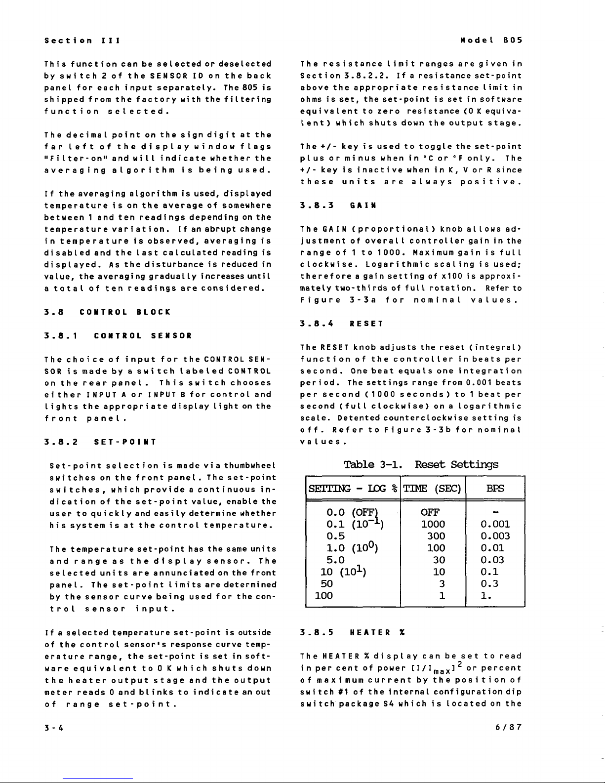
3.8.3
The
justment of overall
range of
clockwise. Logarithmic scaling is used;
therefore a gain setting of
mately two-thirds of
Figure 3-3a for nominal values.
3.8.4
The
function of the controller in beats per
second. One
period. The settings range from
per second
second
scale. Detented counterclockwise setting is
off. Refer to Figure
values.
GAIN
GAIN
(proportional) knoballows ad-
1
RESET
RESET
(full
knob adjuststhe reset (integral)
limit
to 1000. Maximum gain is full
beat
(1
000
clockwise) on a logarithmic
ranges are given
If
a resistance set-point
in
software
(0
K
in
°C
or
°F
only. The
in
K,
V
or R since
controller gain
×100
is approxi-
full
rotation.
equals one integration
0.001
seconds) to 1 beat per
3-3b
for nominal
in
limit
in
equiva-
in
the
Refer to
beats
Set-point selection is made via thumbwheel
switches on the front panel. The set-point
in
in-
soft-
switches, which provide a continuous
dication of the set-point value, enable the
user to quickly and easily determine whether
his system is at the control temperature.
The temperature set-point has the same units
and range as the display sensor. The
selected units are annunciated on the front
panel. The set-point limits
by the sensor curve being used for the con-
trol sensor input.
If
a selected temperature set-point is outside
of the control sensor's response curve temperature range, the set-point is set
0
ware equivalent to
the heater output stage and the output
0
meter reads
of range set-point.
3-4
and blinks to indicateanout
K
are determined
which shuts down
Table
SETTING
-
3-1.
LLX
%
TIME
0.5
1.0
(100)
5.0
10
(101)
50
100
3.8.5
The
in
per cent of power
of maximum current
switch
switch package
HEATER
HEATER
%display can be set to read
#1
of the internal configuration dip
%
[I/Imax]2
S4
which is located on the
Reset
Settings
(SEC)
OFT
1000
300
100
30
10
3
1
by
the position of
0.001
0.003
0.01
0.03
0.1
0.3
1.
or percent
BFS
-
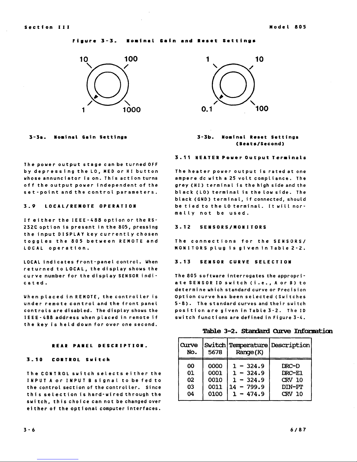
Figure
3-3.
Nominal Cain
and
Reset Settings
3-3a.
The power output stage can
by
depressing the
whose annunciator is on. This action turns
off the output power independent of the
set-point andthe
3.9
If
either the IEEE-488 option or the
232C option is present
the
toggles the 805 between
LOCAL
LOCAL
returned to
curve number for the display
cated.
When placed
under remote control and the front panel
controls are disabled. The display shows the
IEEE-488 address when placed in remote
the key is held down for over one second.
Nominal
LOCAL/REMOTE OPERATION
input
DISPLAY
operation.
indicates front-panel control. When
Gain
control parameters.
key currently chosen
LOCAL,
in
REMOTE,
Settings
be
turned
LO,
MED
or
HI
button
in
the 805, pressing
REMOTE
the display shows the
SENSOR
the controller is
indi-
OFF
RS-
and
if
3-3b.
3.11
The heater power output is rated at one
ampere dc with a 25 volt compliance. The
grey
black
black
be tied to the
mally not be used.
3.12
The connections for the
MONITORS
3.13
The 805 software interrogates the appropriate
determine
Option curve has been selected
5-8).
position are given
switch functions are defined
HEATER
(HI)
(LO)
(GND)
SENSORS/MONITORS
SENSOR CURVE SELECTION
SENSOR
The standard curves and their switch
Table
Nominal Reset Settings
(Beats/Second)
Power
terminal is the
terminal is the Low side. The
terminal,
LO
plug is given
ID
switch
which
standard curve or Precision
3-2.
Output
high
if
connected, should
terminal.
in
(i.e.,
in
Table3-2. The
Standard
Terminals
side and the
It
will
SENSORS/
Table
A
or
(Switches
in
Figure 3-4.
Curve
nor-
2-2.
B)
to
ID
Information
REAR PANEL DESCRIPTION.
3.10
The
INPUT
the control section of the controller. Since
this
switch, this choice can not be
either of the optional computer interfaces.
CONTROL Switch
CONTROL
A
selection ishard-wiredthrough
switch selects either the
or INPUT B signal to be fed to
3-6
the
changed over
Curve
No.
00
01
02
03
04
Switch
5678
0000
0001
0010
0011
0100
1
1
1
14
1
Range
-
324.9
-
324.9
-
324.9
-
799.9
-
474.9
(K)
DRC-D
DRC-E1
CRV
10
DIN-PT
CRV
10
 Loading...