

Lake Shore 648 User Manual
User’s Manual
Model 648
Electromagnet Power Supply
Lake Shore Cryotronics, Inc.
575 McCorkle Blvd.
Westerville, Ohio 43082-8888 USA
sales@lakeshore.com
service@lakeshore.com
www.lakeshore.com
Fax: (614) 891-1392
Telephone: (614) 891-2243
Methods and apparatus disclosed and described herein have been developed solely on company funds of Lake Shore
Cryotronics, Inc. No government or other contractual support or relationship whatsoever has existed which in any
way affects or mitigates proprietary rights of Lake Shore Cryotronics, Inc. in these developments. Methods and
apparatus disclosed herein may be subject to U.S. Patents existing or applied for.
Lake Shore Cryotronics, Inc. reserves the right to add, improve, modify, or withdraw functions, design modifications,
or products at any time without notice. Lake Shore shall not be liable for errors contained herein or for incidental or
consequential damages in connection with furnishing, performance, or use of this material.
Rev. 1.4 P/N 119-058 25 July 2017
| www.lakeshore.com

LIMITED WARRANTY STATEMENT
WARRANTY PERIOD: THREE (3) YEARS
1. Lake Shore warrants that products manufactured by Lake Shore
(the "Product”) will be free from defects in materials and work
manship for three years from the date of Purchaser's physical
receipt of the Product (the "Warranty Period"). If Lake Shore
receives notice of any such defects during the Warranty Period
and the defective Product is shipped freight prepaid back to
Lake Shore, Lake Shore will, at its option, either repair or replace
the Product (if it is so defective) without charge for parts, service
labor or associated customary return shipping cost to the Pur
chaser. Replacement for the Product may be by either new or
equivalent in performance to new. Replacement or repaired
parts, or a replaced Product, will be warranted for only the
unexpired portion of the original warranty or 90 days (which
ever is greater).
2. Lake Shore warrants the Product only if the Product has been
sold by an authorized Lake Shore employee, sales representa
tive, dealer or an authorized Lake Shore original equipment
manufacturer (OEM).
3. The Product may contain remanufactured parts equivalent to
new in performance or may have been subject to incidental use
when it is originally sold to the Purchaser.
4. The Warranty Period begins on the date the Product ships from
Lake Shore’s plant.
5. This limited warranty does not apply to defects in the Product
resulting from (a) improper or inadequate installation (unless
OT&V services are performed by Lake Shore), maintenance,
repair or calibration, (b) fuses, software, power surges, lightning
and non-rechargeable batteries, (c) software, interfacing, parts
or other supplies not furnished by Lake Shore, (d) unauthorized
modification or misuse, (e) operation outside of the published
specifications, (f) improper site preparation or site maintenance
(g) natural disasters such as flood, fire, wind, or earthquake, or
(h) damage during shipment other than original shipment to
you if shipped through a Lake Shore carrier.
6. This limited warranty does not cover: (a) regularly scheduled or
ordinary and expected recalibrations of the Product; (b) acces
sories to the Product (such as probe tips and cables, holders,
wire, grease, varnish, feedthroughs, etc.); (c) consumables used
in conjunction with the Product (such as probe tips and cables,
probe holders, sample tails, rods and holders, ceramic putty for
mounting samples, Hall sample cards, Hall sample enclosures,
etc.); or, (d) non-Lake Shore branded Products that are inte
grated with the Product.
7. To the extent allowed by applicable law, this limited warranty is
the only warranty applicable to the Product and replaces all
other warranties or conditions, express or implied, including,
but not limited to, the implied warranties or conditions of mer
chantability and fitness for a particular purpose. Specifically,
except as provided herein,
-
-
-
-
-
Lake Shore undertakes no responsibility that the products will
be fit for any particular purpose for which you may be buying
the Products. Any implied warranty is limited in duration to the
warranty period. No oral or written information, or advice given
-
-
by the Company, its Agents or Employees, shall create a war
ranty or in any way increase the scope of this limited warranty.
Some countries, states or provinces do not allow limitations on
an implied warranty, so the above limitation or exclusion might
not apply to you. This warranty gives you specific legal rights
and you might also have other rights that vary from country to
country, state to state or province to province.
8. Further, with regard to the United Nations Convention for International Sale of Goods (CISC,) if CI SG is found to apply in relation
to this agreement, which is specifically disclaimed by Lake
Shore, then this limited warranty excludes warranties that: (a)
the Product is fit for the purpose for which goods of the same
description would ordinarily be used, (b) the Product is fit for
any particular purpose expressly or impliedly made known to
Lake Shore at the time of the conclusion of the contract. (c) the
Product is contained or packaged in a manner usual for such
goods or in a manner adequate to preserve and protect such
goods where it is shipped by someone other than a carrier hired
by Lake Shore.
9. Lake Shore disclaims any warranties o f technological value or of
non-infringement with respect to the Product and Lake Shore
shall have no duty to defend, indemnify, or hold harmless you
from and against any or all damages or costs incurred by you
arising from the infringement of patents or trademarks or viola
tion or copyrights by the Product.
10. THIS WARRANTY IS NOT TRANSFERRABLE. This warranty is not
transferable.
11. Except to the extent prohibited by applicable law, neither Lake
Shore nor any of its subsidiaries, affiliates or suppliers will be
held liable for direct, special, incidental, consequential or other
damages (including lost profit, lost data, or downtime costs)
arising out of the use, inability to use or result of use of the prod
uct, whether based in warranty, contract, tort or other legal theory, regardless whether or not Lake Shore has been advised of
the possibility of such damages. Purchaser's use of the Product
is entirely at Purchaser's risk. Some countries, states and prov
inces do not allow the exclusion of liability for incidental or consequential damages, so the above limitation may not apply to
you.
12. This limited warranty gives you specific legal rights, and you
may also have other rights that vary within or between jurisdic
tions where the product is purchased and/or used. Some jurisdictions do not allow limitation in certain warranties, and so the
above limitations or exclusions of some warranties stated above
may not apply to you.
13. Except to the extent allowed by applicable law, the terms of this
limited warranty statement do not exclude, restrict or modify
the mandatory statutory rights applicable to the sale of the
product to you.
-
-
-
-
-
Model 648 Electromagnet Power Supply

Copyright 2012-2017 Lake Shore Cryotronics, Inc. All rights reserved. No portion of this manual may be reproduced,
stored in a retrieval system, or transmitted, in any form or by any means, electronic, mechanical, photocopying,
recording, or otherwise, without the express written permission of Lake Shore.
CERTIFICATION
Lake Shore certifies that this product has been inspected and tested
in accordance with its published specifications and that this product
met its published specifications at the time of shipment. The accuracy and calibration of this product at the tim
able to the United States National Institute of Standards and
T
echnology (NIST); formerly known as the National Bureau of Stan-
dards (NBS).
e of shipment are trace-
FIRMWARE LIMITATIONS
Lake Shore has worked to ensure that the Model 648 firmware is as
free of errors as possible, and that the results you obtain from the
instrument are accurate and reliable. However, as with any computer-based software, the possibi
In any important research, as when us
results should be carefully examined and rechecked before final conclusions are drawn. Neither Lake Shore nor anyone else involved in
creation or production of this firmware can pay for loss of time,
the
inconvenience, loss of use of the product, or property damage caused
by this product or its failure to work, or any other incidental or consequential damages. Use of our product impl
the Lake Shore license agreement and statement of limited warranty.
lity of errors exists.
ing any laboratory equipment,
ies that you understand
FIRMWARE LICENSE AGREEMENT
The firmware in this instrument is protected by United States copyright law and international treaty pr
ranty, the code contained in the firmware must not be modified. Any
anges made to the code is at the user's risk. Lake Shore will assume
ch
no responsibility for damage or errors incurred as result of any
changes made to the firmware.
ovisions. To maintain the war-
Firmware License Agreement, continued:
Under the terms of this agreement you may only use the Model 648
mware as physically installed in the in strument. Archival copies are
fir
strictly forbidden. You may not decompile, disassemble, or reverse
engineer the firmware. If you suspect there are problems with the
firmware, return the instrument to Lake Shore for repair under the
terms of the Limited Warranty specified above. Any unauthorized
duplication or use of the Model 648 firmware in whole or in part, in
print, or in any other storage and retrieval system is forbidden.
TRADEMARK ACKNOWLEDGMENT
Many manufacturers and sellers claim designations used to distinguish their products as trademarks. Where those designations
ear in this manual and Lake Shore was aware of a trademark
app
claim, they appear with initial capital letters and the ™ or ® symbol.
Alumel™ and Chromel™ are trademarks of
Conceptech, Inc., Corporation
CalCurve™, Cernox™, SoftCal™, Rox™, Curve Handler™ are trademarks of Lake Shore Cryotronics, Inc.
Java™ is a registered trademark of Sun Microsystems, Inc.
of Santa Clara, CA
LabVIEW® is a registered trademark of National Instruments.
Mac® is a registered trademark of Apple, Inc., registered in the U.S and
other countrie
Microsoft Windows®, Excel®, and Windows Vista® are registered
demarks of Microsoft Corporation in the United States and other
tra
countries.
Stycast® is a trademark of Emerson & Cuming.
WinZip™ is a registered trademark of Nico Mak of Connecticut.
s.
| www.lakeshore.com

EU DECLARATION OF CONFORMITY
This declaration of conformity is issued under the sole responsibility of the manufacturer.
Manufacturer:
Lake Shore Cryotronics, Inc.
575 McCorkle Boulevard
Westerville, OH 43082
USA
Object of the declaration:
Model(s): 648
Description: Electromagnet Power Supply
The object of the declaration described above is in conformity with the relevant Union harmonization
legislation:
2014/35/EU Low Voltage Directive
2014/30/EU EMC Directive
2011/65/EU RoHS
References to the relevant harmonized standards used to the specification in relation to which
conformity is declared:
EN 61010-1:2010
Overvoltage Category II
Pollution Degree 2
EN 61326-1:2013
Class A
Controlled Electromagnetic Environment
EN 50581:2012
Signed for and on behalf of:
Place, Date:
Westerville, OH USA Scott Ayer
29-SEP-2016 Director of Quality & Compliance
Model 648 Electromagnet Power Supply

Electromagnetic Compatibility (EMC) for the Model 648 Electromagnet Power Supply
Electromagnetic Compatibility (EMC) of electronic equipment is a growing concern worldwide. Emissions of and
immunity to electromagnetic interference is now part of the design and manufacture of most electronics. To qualify
for the CE Mark, the Model 648 meets or exceeds the requirements of the European EMC Directive 89/643/EEC as a
CLASS A product. A Class A product is allowed to radiate more RF than a Class B product and must include the follow
ing warning:
WARNING:This is a Class A product. In a domestic environment, this product may cause radio interference in which
case the user may be required to take adequate measures.
The instrument was tested under normal operating conditions with sensor and interface cables attached. If the
installation and operating instructions in the User's Manual are followed, there should be no degradation in EMC
performance.
This instrument is not intended for use in close proximity to RF Transmitters such as two-way radios and cell
phones. Exposure to RF interference greater than that found in a typical laboratory environment may disturb the
sensitive measurement circuitry of the instrument.
Pay special attention to instrument cabling. Improperly installed cabling may defeat even the best EMC protection.
For the best performance from any precision instrument, follow the grounding and shielding instructions in the
User's Manual. In addition, the installer of the Model 648 should consider the following:
-
D Shield measurement and computer interface cables.
D Leave no unused or unterminated cables attached to the instrument.
D Make cable runs as short and direct as possible. Higher radiated emissions are possible with long cables.
D Do not tightly bundle cables that carry different types of signals.
D When the instrument is subjected to EM fields of 1 V/m, the output voltage reading may shift as much as ±0.1V.
| www.lakeshore.com

Model 648 Electromagnet Power Supply

i
Table of Contents
Chapter 1
Introduction
Chapter 2
Magnet System
Design, Installation,
and Operation
1.1 Product Description . . . . . . . . . . . . . . . . . . . . . . . . . . . . . . . . . . . . . . . . . . . . . . . . . . . . . . . . . . . . . . . . . . 1
1.2 Output Architecture . . . . . . . . . . . . . . . . . . . . . . . . . . . . . . . . . . . . . . . . . . . . . . . . . . . . . . . . . . . . . . . . . . 2
1.3 Output Programming . . . . . . . . . . . . . . . . . . . . . . . . . . . . . . . . . . . . . . . . . . . . . . . . . . . . . . . . . . . . . . . . 2
1.4 Output Reading . . . . . . . . . . . . . . . . . . . . . . . . . . . . . . . . . . . . . . . . . . . . . . . . . . . . . . . . . . . . . . . . . . . . . . . 2
1.5 Protection . . . . . . . . . . . . . . . . . . . . . . . . . . . . . . . . . . . . . . . . . . . . . . . . . . . . . . . . . . . . . . . . . . . . . . . . . . . . . 2
1.6 Interfaces . . . . . . . . . . . . . . . . . . . . . . . . . . . . . . . . . . . . . . . . . . . . . . . . . . . . . . . . . . . . . . . . . . . . . . . . . . . . . 2
1.7 Display and Keypad . . . . . . . . . . . . . . . . . . . . . . . . . . . . . . . . . . . . . . . . . . . . . . . . . . . . . . . . . . . . . . . . . . . 2
1.8 3-Year Warranty and Technical Support . . . . . . . . . . . . . . . . . . . . . . . . . . . . . . . . . . . . . . . . . . . . . 2
1.9 Model 648 Specifications . . . . . . . . . . . . . . . . . . . . . . . . . . . . . . . . . . . . . . . . . . . . . . . . . . . . . . . . . . . . 3
1.9.1 Output . . . . . . . . . . . . . . . . . . . . . . . . . . . . . . . . . . . . . . . . . . . . . . . . . . . . . . . . . . . . . . . . . . . . . . . . . 3
1.9.2 Output Programming . . . . . . . . . . . . . . . . . . . . . . . . . . . . . . . . . . . . . . . . . . . . . . . . . . . . . . . . . . 3
1.9.3 Readings . . . . . . . . . . . . . . . . . . . . . . . . . . . . . . . . . . . . . . . . . . . . . . . . . . . . . . . . . . . . . . . . . . . . . . . 4
1.9.4 Front Panel . . . . . . . . . . . . . . . . . . . . . . . . . . . . . . . . . . . . . . . . . . . . . . . . . . . . . . . . . . . . . . . . . . . . . 4
1.9.5 Interface . . . . . . . . . . . . . . . . . . . . . . . . . . . . . . . . . . . . . . . . . . . . . . . . . . . . . . . . . . . . . . . . . . . . . . . 4
1.10 General . . . . . . . . . . . . . . . . . . . . . . . . . . . . . . . . . . . . . . . . . . . . . . . . . . . . . . . . . . . . . . . . . . . . . . . . . . . . . . 5
1.11 Ordering Information . . . . . . . . . . . . . . . . . . . . . . . . . . . . . . . . . . . . . . . . . . . . . . . . . . . . . . . . . . . . . . . 6
1.12 Safety Summary and Symbols . . . . . . . . . . . . . . . . . . . . . . . . . . . . . . . . . . . . . . . . . . . . . . . . . . . . . . 7
2.1 General . . . . . . . . . . . . . . . . . . . . . . . . . . . . . . . . . . . . . . . . . . . . . . . . . . . . . . . . . . . . . . . . . . . . . . . . . . . . . . . . 9
2.2 Major Components of the Magnet . . . . . . . . . . . . . . . . . . . . . . . . . . . . . . . . . . . . . . . . . . . . . . . . . . . 9
2.3 Magnet Construction . . . . . . . . . . . . . . . . . . . . . . . . . . . . . . . . . . . . . . . . . . . . . . . . . . . . . . . . . . . . . . . .10
2.4 Connecting the Magnet . . . . . . . . . . . . . . . . . . . . . . . . . . . . . . . . . . . . . . . . . . . . . . . . . . . . . . . . . . . . .10
2.4.1 Water Hose Connection . . . . . . . . . . . . . . . . . . . . . . . . . . . . . . . . . . . . . . . . . . . . . . . . . . . . . .10
2.4.2 Magnet Coil Wiring . . . . . . . . . . . . . . . . . . . . . . . . . . . . . . . . . . . . . . . . . . . . . . . . . . . . . . . . . . . 11
2.4.3 Temperature Switches and Flow Switches . . . . . . . . . . . . . . . . . . . . . . . . . . . . . . . . . . . 12
2.4.4 Cooling Water and Water Valve . . . . . . . . . . . . . . . . . . . . . . . . . . . . . . . . . . . . . . . . . . . . . . 12
2.4.5 Grounding . . . . . . . . . . . . . . . . . . . . . . . . . . . . . . . . . . . . . . . . . . . . . . . . . . . . . . . . . . . . . . . . . . . . 13
2.4.6 Final Check-Out . . . . . . . . . . . . . . . . . . . . . . . . . . . . . . . . . . . . . . . . . . . . . . . . . . . . . . . . . . . . . . . 13
2.5 Electromagnet Operation . . . . . . . . . . . . . . . . . . . . . . . . . . . . . . . . . . . . . . . . . . . . . . . . . . . . . . . . . . . 13
2.5.1 Air Gap and Pole Caps . . . . . . . . . . . . . . . . . . . . . . . . . . . . . . . . . . . . . . . . . . . . . . . . . . . . . . . . . 13
2.5.2 Maximum Current and Power . . . . . . . . . . . . . . . . . . . . . . . . . . . . . . . . . . . . . . . . . . . . . . . .13
2.5.3 Operation Under Field Control . . . . . . . . . . . . . . . . . . . . . . . . . . . . . . . . . . . . . . . . . . . . . . . 15
2.5.4 Avoiding Cooling Water Condensation . . . . . . . . . . . . . . . . . . . . . . . . . . . . . . . . . . . . . . . 15
Chapter 3
Installation
3.1 General . . . . . . . . . . . . . . . . . . . . . . . . . . . . . . . . . . . . . . . . . . . . . . . . . . . . . . . . . . . . . . . . . . . . . . . . . . . . . . .17
3.2 Inspection and Unpacking . . . . . . . . . . . . . . . . . . . . . . . . . . . . . . . . . . . . . . . . . . . . . . . . . . . . . . . . . .17
3.3 Rear Panel Definition . . . . . . . . . . . . . . . . . . . . . . . . . . . . . . . . . . . . . . . . . . . . . . . . . . . . . . . . . . . . . . . . 18
3.4 Power Wiring and Setup . . . . . . . . . . . . . . . . . . . . . . . . . . . . . . . . . . . . . . . . . . . . . . . . . . . . . . . . . . . . . 19
3.5 Magnet Connector . . . . . . . . . . . . . . . . . . . . . . . . . . . . . . . . . . . . . . . . . . . . . . . . . . . . . . . . . . . . . . . . . . .25
3.6 Auxiliary Connector . . . . . . . . . . . . . . . . . . . . . . . . . . . . . . . . . . . . . . . . . . . . . . . . . . . . . . . . . . . . . . . . . . 25
3.7 Power Supply Connector . . . . . . . . . . . . . . . . . . . . . . . . . . . . . . . . . . . . . . . . . . . . . . . . . . . . . . . . . . . . 26
3.8 Cooling Water . . . . . . . . . . . . . . . . . . . . . . . . . . . . . . . . . . . . . . . . . . . . . . . . . . . . . . . . . . . . . . . . . . . . . . .26
3.9 Magnet Cable Connections . . . . . . . . . . . . . . . . . . . . . . . . . . . . . . . . . . . . . . . . . . . . . . . . . . . . . . . . . 28
3.2.1 Moving and Handling . . . . . . . . . . . . . . . . . . . . . . . . . . . . . . . . . . . . . . . . . . . . . . . . . . . . . . . .18
3.4.1 Line Voltage Selection . . . . . . . . . . . . . . . . . . . . . . . . . . . . . . . . . . . . . . . . . . . . . . . . . . . . . . . . 20
3.4.2 Circuit Breaker Setting . . . . . . . . . . . . . . . . . . . . . . . . . . . . . . . . . . . . . . . . . . . . . . . . . . . . . . . .20
3.4.3 Start-up Fuses . . . . . . . . . . . . . . . . . . . . . . . . . . . . . . . . . . . . . . . . . . . . . . . . . . . . . . . . . . . . . . . . 21
3.4.4 Cable Entry . . . . . . . . . . . . . . . . . . . . . . . . . . . . . . . . . . . . . . . . . . . . . . . . . . . . . . . . . . . . . . . . . . . .21
3.4.5 Power Input Terminals . . . . . . . . . . . . . . . . . . . . . . . . . . . . . . . . . . . . . . . . . . . . . . . . . . . . . . . 23
3.4.6 Wiring Cover . . . . . . . . . . . . . . . . . . . . . . . . . . . . . . . . . . . . . . . . . . . . . . . . . . . . . . . . . . . . . . . . . . 24
3.4.7 Mains Wiring . . . . . . . . . . . . . . . . . . . . . . . . . . . . . . . . . . . . . . . . . . . . . . . . . . . . . . . . . . . . . . . . . 25
| www.lakeshore.com

3.10 Analog Input/Output Connections . . . . . . . . . . . . . . . . . . . . . . . . . . . . . . . . . . . . . . . . . . . . . . . . 29
3.10.1 External Current Programming . . . . . . . . . . . . . . . . . . . . . . . . . . . . . . . . . . . . . . . . . . . . . 29
3.10.2 Output Current and Voltage Monitors . . . . . . . . . . . . . . . . . . . . . . . . . . . . . . . . . . . . . . 29
3.11 Computer Interface . . . . . . . . . . . . . . . . . . . . . . . . . . . . . . . . . . . . . . . . . . . . . . . . . . . . . . . . . . . . . . . . 29
3.11.1 USB Interface Connection . . . . . . . . . . . . . . . . . . . . . . . . . . . . . . . . . . . . . . . . . . . . . . . . . . 29
3.11.2 IEEE-488 Interface Connection . . . . . . . . . . . . . . . . . . . . . . . . . . . . . . . . . . . . . . . . . . . . 30
3.12 Chassis Connection . . . . . . . . . . . . . . . . . . . . . . . . . . . . . . . . . . . . . . . . . . . . . . . . . . . . . . . . . . . . . . . . 30
3.12.1 3-Phase Power Connections . . . . . . . . . . . . . . . . . . . . . . . . . . . . . . . . . . . . . . . . . . . . . . . . 30
3.12.2 Attach the Floor Mounting Option . . . . . . . . . . . . . . . . . . . . . . . . . . . . . . . . . . . . . . . . . 30
Chapter 4
Operation
4.1 General . . . . . . . . . . . . . . . . . . . . . . . . . . . . . . . . . . . . . . . . . . . . . . . . . . . . . . . . . . . . . . . . . . . . . . . . . . . . . . 31
4.1.1 Understanding Menu Navigation . . . . . . . . . . . . . . . . . . . . . . . . . . . . . . . . . . . . . . . . . . . . 31
4.2 Turning Power On . . . . . . . . . . . . . . . . . . . . . . . . . . . . . . . . . . . . . . . . . . . . . . . . . . . . . . . . . . . . . . . . . . . 31
4.3 Display Definition . . . . . . . . . . . . . . . . . . . . . . . . . . . . . . . . . . . . . . . . . . . . . . . . . . . . . . . . . . . . . . . . . . . 32
4.4 LED Annunciators . . . . . . . . . . . . . . . . . . . . . . . . . . . . . . . . . . . . . . . . . . . . . . . . . . . . . . . . . . . . . . . . . . . 32
4.4.1 Fault LED . . . . . . . . . . . . . . . . . . . . . . . . . . . . . . . . . . . . . . . . . . . . . . . . . . . . . . . . . . . . . . . . . . . . . . 33
4.4.2 Compliance LED . . . . . . . . . . . . . . . . . . . . . . . . . . . . . . . . . . . . . . . . . . . . . . . . . . . . . . . . . . . . . . 33
4.4.3 Power Limit LED . . . . . . . . . . . . . . . . . . . . . . . . . . . . . . . . . . . . . . . . . . . . . . . . . . . . . . . . . . . . . . . 33
4.4.4 Ramping LED . . . . . . . . . . . . . . . . . . . . . . . . . . . . . . . . . . . . . . . . . . . . . . . . . . . . . . . . . . . . . . . . . . 33
4.4.5 Remote LED . . . . . . . . . . . . . . . . . . . . . . . . . . . . . . . . . . . . . . . . . . . . . . . . . . . . . . . . . . . . . . . . . . . 33
4.5 Keypad Definition . . . . . . . . . . . . . . . . . . . . . . . . . . . . . . . . . . . . . . . . . . . . . . . . . . . . . . . . . . . . . . . . . . . 33
4.5.1 General Keypad Operation . . . . . . . . . . . . . . . . . . . . . . . . . . . . . . . . . . . . . . . . . . . . . . . . . . . 34
4.6 Display Setup . . . . . . . . . . . . . . . . . . . . . . . . . . . . . . . . . . . . . . . . . . . . . . . . . . . . . . . . . . . . . . . . . . . . . . . . 35
4.7 Setting Output Current . . . . . . . . . . . . . . . . . . . . . . . . . . . . . . . . . . . . . . . . . . . . . . . . . . . . . . . . . . . . . . 35
4.8 Output Current Ramp Rate . . . . . . . . . . . . . . . . . . . . . . . . . . . . . . . . . . . . . . . . . . . . . . . . . . . . . . . . . 35
4.9 Ramp Segments . . . . . . . . . . . . . . . . . . . . . . . . . . . . . . . . . . . . . . . . . . . . . . . . . . . . . . . . . . . . . . . . . . . . . 36
4.9.1 Setting Up the Ramp Segments Table . . . . . . . . . . . . . . . . . . . . . . . . . . . . . . . . . . . . . . . 36
4.10 Pause Output . . . . . . . . . . . . . . . . . . . . . . . . . . . . . . . . . . . . . . . . . . . . . . . . . . . . . . . . . . . . . . . . . . . . . . 36
4.11 Zero Output . . . . . . . . . . . . . . . . . . . . . . . . . . . . . . . . . . . . . . . . . . . . . . . . . . . . . . . . . . . . . . . . . . . . . . . . 37
4.12 Maximum Setting Limits . . . . . . . . . . . . . . . . . . . . . . . . . . . . . . . . . . . . . . . . . . . . . . . . . . . . . . . . . . 37
4.12.1 Maximum Output Current . . . . . . . . . . . . . . . . . . . . . . . . . . . . . . . . . . . . . . . . . . . . . . . . . . 37
4.12.2 Maximum Current Ramp Rate . . . . . . . . . . . . . . . . . . . . . . . . . . . . . . . . . . . . . . . . . . . . . . 37
4.13 Magnet Water . . . . . . . . . . . . . . . . . . . . . . . . . . . . . . . . . . . . . . . . . . . . . . . . . . . . . . . . . . . . . . . . . . . . . 37
4.14 Internal Water . . . . . . . . . . . . . . . . . . . . . . . . . . . . . . . . . . . . . . . . . . . . . . . . . . . . . . . . . . . . . . . . . . . . . 38
4.15 Error Status Display . . . . . . . . . . . . . . . . . . . . . . . . . . . . . . . . . . . . . . . . . . . . . . . . . . . . . . . . . . . . . . . . 38
4.16 External Current Programming . . . . . . . . . . . . . . . . . . . . . . . . . . . . . . . . . . . . . . . . . . . . . . . . . . . 39
4.17 Locking the Keypad . . . . . . . . . . . . . . . . . . . . . . . . . . . . . . . . . . . . . . . . . . . . . . . . . . . . . . . . . . . . . . . . 39
4.18 Computer Interface . . . . . . . . . . . . . . . . . . . . . . . . . . . . . . . . . . . . . . . . . . . . . . . . . . . . . . . . . . . . . . . . 40
4.18.1 Changing IEEE-488 Interface Parameters . . . . . . . . . . . . . . . . . . . . . . . . . . . . . . . . . 40
4.19 Default Parameter Values . . . . . . . . . . . . . . . . . . . . . . . . . . . . . . . . . . . . . . . . . . . . . . . . . . . . . . . . . 40
Chapter 5
Computer
Interface Operation
Model 648 Electromagnet Power Supply
5.1 General . . . . . . . . . . . . . . . . . . . . . . . . . . . . . . . . . . . . . . . . . . . . . . . . . . . . . . . . . . . . . . . . . . . . . . . . . . . . . . 41
5.2 IEEE-488 Interface . . . . . . . . . . . . . . . . . . . . . . . . . . . . . . . . . . . . . . . . . . . . . . . . . . . . . . . . . . . . . . . . . . 41
5.2.1 Changing IEEE-488 Interface Parameters . . . . . . . . . . . . . . . . . . . . . . . . . . . . . . . . . . . 42
5.2.2 Remote/Local Operation . . . . . . . . . . . . . . . . . . . . . . . . . . . . . . . . . . . . . . . . . . . . . . . . . . . . . 42
5.2.3 IEEE-488 Command Structure . . . . . . . . . . . . . . . . . . . . . . . . . . . . . . . . . . . . . . . . . . . . . . . 42
5.2.4 Status System Overview . . . . . . . . . . . . . . . . . . . . . . . . . . . . . . . . . . . . . . . . . . . . . . . . . . . . . . 44
5.2.3.1 Bus Control Commands . . . . . . . . . . . . . . . . . . . . . . . . . . . . . . . . . . . . . . . . . . . . . . 42
5.2.3.2 Common Commands . . . . . . . . . . . . . . . . . . . . . . . . . . . . . . . . . . . . . . . . . . . . . . . . . 43
5.2.3.3 Device Specific Commands . . . . . . . . . . . . . . . . . . . . . . . . . . . . . . . . . . . . . . . . . . 43
5.2.3.4 Message Strings . . . . . . . . . . . . . . . . . . . . . . . . . . . . . . . . . . . . . . . . . . . . . . . . . . . . . . 43
5.2.4.1 Condition Registers . . . . . . . . . . . . . . . . . . . . . . . . . . . . . . . . . . . . . . . . . . . . . . . . . . 44
5.2.4.2 Event Registers . . . . . . . . . . . . . . . . . . . . . . . . . . . . . . . . . . . . . . . . . . . . . . . . . . . . . . . 44
5.2.4.3 Enable Registers . . . . . . . . . . . . . . . . . . . . . . . . . . . . . . . . . . . . . . . . . . . . . . . . . . . . . . 44
5.2.4.4 Status Byte Register . . . . . . . . . . . . . . . . . . . . . . . . . . . . . . . . . . . . . . . . . . . . . . . . . . 46
5.2.4.5 Service Request Enable Register . . . . . . . . . . . . . . . . . . . . . . . . . . . . . . . . . . . . . 47
5.2.4.6 Reading Registers . . . . . . . . . . . . . . . . . . . . . . . . . . . . . . . . . . . . . . . . . . . . . . . . . . . . 47

iii
5.2.4.7 Programming Registers . . . . . . . . . . . . . . . . . . . . . . . . . . . . . . . . . . . . . . . . . . . . . . 47
5.2.4.8 Clearing Registers . . . . . . . . . . . . . . . . . . . . . . . . . . . . . . . . . . . . . . . . . . . . . . . . . . . . 47
5.2.5 Status System Detail: Status Register Sets . . . . . . . . . . . . . . . . . . . . . . . . . . . . . . . . . . . 47
5.2.5.1 Standard Event Status Register Set . . . . . . . . . . . . . . . . . . . . . . . . . . . . . . . . . . 48
5.2.5.2 Operation Event Register Set . . . . . . . . . . . . . . . . . . . . . . . . . . . . . . . . . . . . . . . . . 48
5.2.6 Status System Detail: Error Status Register Sets . . . . . . . . . . . . . . . . . . . . . . . . . . . . . 49
5.2.6.1 Hardware Error Status Register Set . . . . . . . . . . . . . . . . . . . . . . . . . . . . . . . . . .49
5.2.6.2 Operational Error Status Register Set . . . . . . . . . . . . . . . . . . . . . . . . . . . . . . . .50
5.2.7 Status System Detail: Status Byte Register and Service Request (SRQ) . . . . . . 51
5.2.7.1 Status Byte Register . . . . . . . . . . . . . . . . . . . . . . . . . . . . . . . . . . . . . . . . . . . . . . . . . .51
5.2.7.2 Service Request Enable Register . . . . . . . . . . . . . . . . . . . . . . . . . . . . . . . . . . . . . 52
5.2.7.3 Using Service Request (SRQ) and Serial Poll . . . . . . . . . . . . . . . . . . . . . . . . .52
5.2.7.4 Using Status Byte Query (*STB?) . . . . . . . . . . . . . . . . . . . . . . . . . . . . . . . . . . . . . 53
5.2.7.5 Using Message Available (MAV)Bit . . . . . . . . . . . . . . . . . . . . . . . . . . . . . . . . . . . 53
5.2.7.6 Using Operation Complete (*OPC) and
Operation Complete Query (*OPC?) . . . . . . . . . . . . . . . . . . . . . . . . . . . . . . . . . 53
5.3 Serial Interface Overview . . . . . . . . . . . . . . . . . . . . . . . . . . . . . . . . . . . . . . . . . . . . . . . . . . . . . . . . . . . . 54
5.3.1 Physical Connection . . . . . . . . . . . . . . . . . . . . . . . . . . . . . . . . . . . . . . . . . . . . . . . . . . . . . . . . . .54
5.3.2 Hardware Support . . . . . . . . . . . . . . . . . . . . . . . . . . . . . . . . . . . . . . . . . . . . . . . . . . . . . . . . . . . . 54
5.3.3 Installing the USB Driver . . . . . . . . . . . . . . . . . . . . . . . . . . . . . . . . . . . . . . . . . . . . . . . . . . . . . 54
5.3.3.1 Installing the Driver From Windows® Update in
Windows Vista® and Windows 7® . . . . . . . . . . . . . . . . . . . . . . . . . . . . . . . . . . . 55
5.3.3.2 Installing the Driver From Windows® Update in Windows® XP . . . . . 55
5.3.3.3 Installing the Driver From the Web . . . . . . . . . . . . . . . . . . . . . . . . . . . . . . . . . .55
5.3.3.3.1 Download the driver . . . . . . . . . . . . . . . . . . . . . . . . . . . . . . . . . . . . . . . . . . . . . . . . . . . . . . . . . . . 55
5.3.3.3.2 Extract the driver . . . . . . . . . . . . . . . . . . . . . . . . . . . . . . . . . . . . . . . . . . . . . . . . . . . . . . . . . . . . . . 55
5.3.3.3.3 Manually install the driver . . . . . . . . . . . . . . . . . . . . . . . . . . . . . . . . . . . . . . . . . . . . . . . . . . . . 56
5.3.3.4 Installing the USB Driver from the Included CD . . . . . . . . . . . . . . . . . . . . .57
5.3.4 Communication . . . . . . . . . . . . . . . . . . . . . . . . . . . . . . . . . . . . . . . . . . . . . . . . . . . . . . . . . . . . . .58
5.3.4.1 Character Format . . . . . . . . . . . . . . . . . . . . . . . . . . . . . . . . . . . . . . . . . . . . . . . . . . . . . 58
5.3.4.2 Message Strings . . . . . . . . . . . . . . . . . . . . . . . . . . . . . . . . . . . . . . . . . . . . . . . . . . . . . .58
5.3.5 Message Flow Control . . . . . . . . . . . . . . . . . . . . . . . . . . . . . . . . . . . . . . . . . . . . . . . . . . . . . . . . 58
5.4 Command Summary . . . . . . . . . . . . . . . . . . . . . . . . . . . . . . . . . . . . . . . . . . . . . . . . . . . . . . . . . . . . . . . .59
Chapter 6
Service
6.1 General . . . . . . . . . . . . . . . . . . . . . . . . . . . . . . . . . . . . . . . . . . . . . . . . . . . . . . . . . . . . . . . . . . . . . . . . . . . . . . .69
6.2 USB Troubleshooting . . . . . . . . . . . . . . . . . . . . . . . . . . . . . . . . . . . . . . . . . . . . . . . . . . . . . . . . . . . . . . . .69
6.2.1 New Installation . . . . . . . . . . . . . . . . . . . . . . . . . . . . . . . . . . . . . . . . . . . . . . . . . . . . . . . . . . . . . . 69
6.2.2 Existing Installation No Longer Working . . . . . . . . . . . . . . . . . . . . . . . . . . . . . . . . . . . . . 69
6.2.3 Intermittent Lockups . . . . . . . . . . . . . . . . . . . . . . . . . . . . . . . . . . . . . . . . . . . . . . . . . . . . . . . . . 69
6.3 IEEE Interface Troubleshooting . . . . . . . . . . . . . . . . . . . . . . . . . . . . . . . . . . . . . . . . . . . . . . . . . . . . . 70
6.3.1 New Installation . . . . . . . . . . . . . . . . . . . . . . . . . . . . . . . . . . . . . . . . . . . . . . . . . . . . . . . . . . . . . . 70
6.3.2 Existing Installation No Longer Working . . . . . . . . . . . . . . . . . . . . . . . . . . . . . . . . . . . . . 70
6.3.3 Intermittent Lockups . . . . . . . . . . . . . . . . . . . . . . . . . . . . . . . . . . . . . . . . . . . . . . . . . . . . . . . . . 70
6.4 Fuse Drawer . . . . . . . . . . . . . . . . . . . . . . . . . . . . . . . . . . . . . . . . . . . . . . . . . . . . . . . . . . . . . . . . . . . . . . . . .70
6.5 Line Voltage Selection . . . . . . . . . . . . . . . . . . . . . . . . . . . . . . . . . . . . . . . . . . . . . . . . . . . . . . . . . . . . . . .71
6.6 Circuit Breaker Setting . . . . . . . . . . . . . . . . . . . . . . . . . . . . . . . . . . . . . . . . . . . . . . . . . . . . . . . . . . . . . .72
6.7 Power Line Fuse Replacement . . . . . . . . . . . . . . . . . . . . . . . . . . . . . . . . . . . . . . . . . . . . . . . . . . . . . .73
6.8 Factory Reset Menu . . . . . . . . . . . . . . . . . . . . . . . . . . . . . . . . . . . . . . . . . . . . . . . . . . . . . . . . . . . . . . . . .74
6.8.1 Default Values . . . . . . . . . . . . . . . . . . . . . . . . . . . . . . . . . . . . . . . . . . . . . . . . . . . . . . . . . . . . . . . .74
6.9 Error Messages . . . . . . . . . . . . . . . . . . . . . . . . . . . . . . . . . . . . . . . . . . . . . . . . . . . . . . . . . . . . . . . . . . . . . .74
6.9.1 Types of Error Messages . . . . . . . . . . . . . . . . . . . . . . . . . . . . . . . . . . . . . . . . . . . . . . . . . . . . . . 74
6.10 Calibration Procedure . . . . . . . . . . . . . . . . . . . . . . . . . . . . . . . . . . . . . . . . . . . . . . . . . . . . . . . . . . . . . 75
6.11 Connector and Cable Definitions . . . . . . . . . . . . . . . . . . . . . . . . . . . . . . . . . . . . . . . . . . . . . . . . . .76
6.11.1 Analog I/O Connector . . . . . . . . . . . . . . . . . . . . . . . . . . . . . . . . . . . . . . . . . . . . . . . . . . . . . . . 76
6.11.2 Magnet Water Connector . . . . . . . . . . . . . . . . . . . . . . . . . . . . . . . . . . . . . . . . . . . . . . . . . . . 76
6.11.3 Auxiliary Connector . . . . . . . . . . . . . . . . . . . . . . . . . . . . . . . . . . . . . . . . . . . . . . . . . . . . . . . . . 77
6.11.4 Power Supply Water Connectors . . . . . . . . . . . . . . . . . . . . . . . . . . . . . . . . . . . . . . . . . . . 78
| www.lakeshore.com

6.11.4.1 Flow Switch . . . . . . . . . . . . . . . . . . . . . . . . . . . . . . . . . . . . . . . . . . . . . . . . . . . . . . . . . 78
6.11.4.2 Water Control Valve . . . . . . . . . . . . . . . . . . . . . . . . . . . . . . . . . . . . . . . . . . . . . . . . 78
6.11.5 USB Connector . . . . . . . . . . . . . . . . . . . . . . . . . . . . . . . . . . . . . . . . . . . . . . . . . . . . . . . . . . . . . . 79
6.12 Technical Inquiries . . . . . . . . . . . . . . . . . . . . . . . . . . . . . . . . . . . . . . . . . . . . . . . . . . . . . . . . . . . . . . . . . 79
6.12.1 Contacting Lake Shore . . . . . . . . . . . . . . . . . . . . . . . . . . . . . . . . . . . . . . . . . . . . . . . . . . . . . . 79
6.12.2 Return of Equipment . . . . . . . . . . . . . . . . . . . . . . . . . . . . . . . . . . . . . . . . . . . . . . . . . . . . . . . . 80
6.12.3 RMA Valid Period . . . . . . . . . . . . . . . . . . . . . . . . . . . . . . . . . . . . . . . . . . . . . . . . . . . . . . . . . . . . 80
6.12.4 Shipping Charges . . . . . . . . . . . . . . . . . . . . . . . . . . . . . . . . . . . . . . . . . . . . . . . . . . . . . . . . . . . 80
6.12.5 Restocking Fee . . . . . . . . . . . . . . . . . . . . . . . . . . . . . . . . . . . . . . . . . . . . . . . . . . . . . . . . . . . . . . 80
Model 648 Electromagnet Power Supply

1 . 1 P r o d u c t D e s c r i p t i o n 1
Chapter 1: Introduction
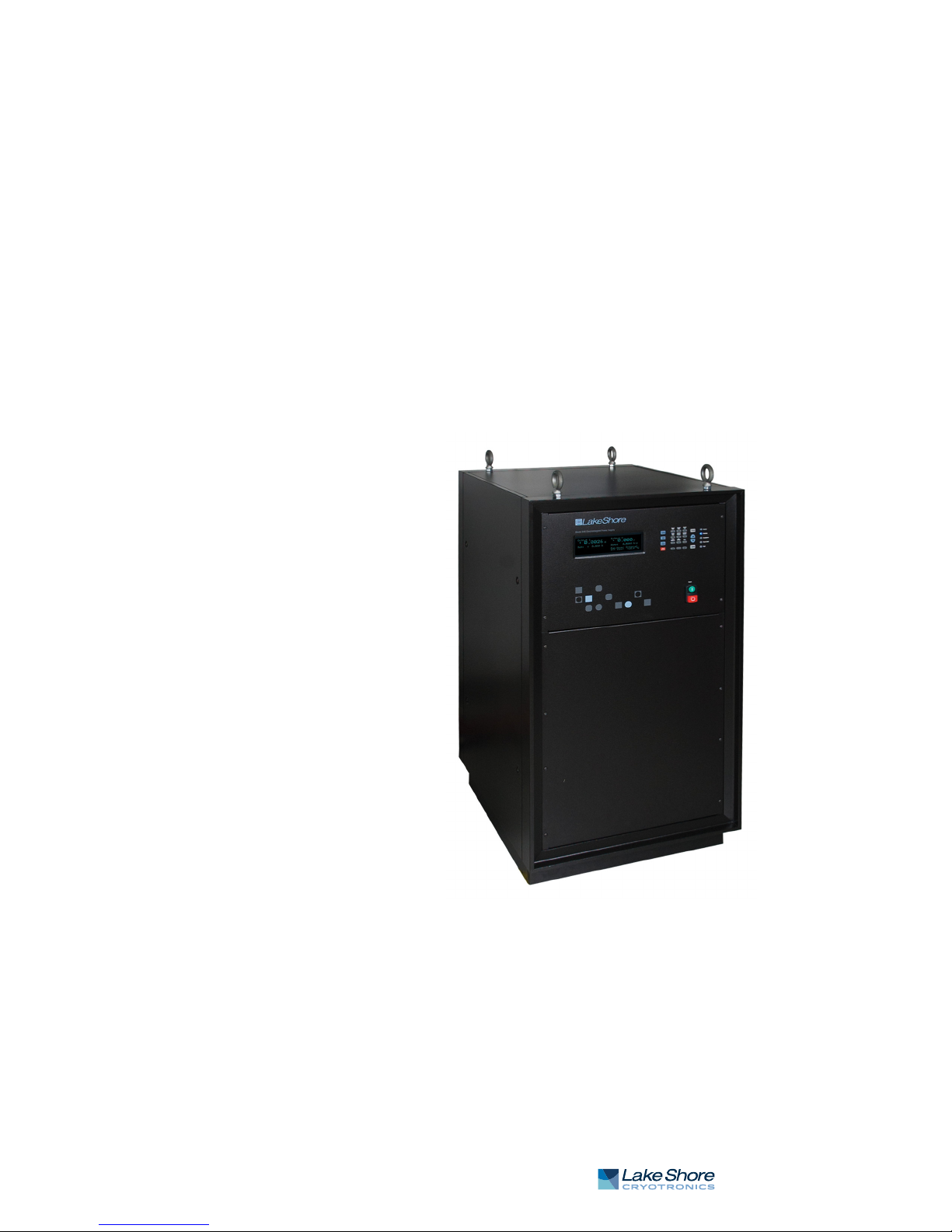
1.1 Product
Description
FIGURE 1-1 Model 648 front view
Features:
D Bipolar
D ±
D Low noise
D 1 m
D A
D Buil
The Model 648 electromagnet power supply is a
optimized for powering large 7 or 10 in research electromagnets. It is specifically
designed for high precision laboratory use requiring extremely low electrical noise.
The linear design removes undesirable higher frequency noise typical of switch mode
power supplies. Eliminating the need for external switching or operator intervention
to reverse current polarity, the Model 648 uses convenient bipolar, 4-quadrant operation. It is capable of supplying ±13
Model 648 is built to last with a rugged design, integrated fault protection, and a simple, clean interior electronic design.
This robust power supply is developed to minimiz
water cooling for quiet efficient operation compared to air-cooled power supplies.
The seamless water lines only have external junctions, eliminating internal water
leaks. In addition, safety interlocks ensure that magnet cooling water is always flowing to the supply while operating. Water can be interlocked into the power supply if
ired. Internal software controls manage water usage intelligently.
des
, linear, true 4-quadrant output
135 A/±75 V, 9.1 kW
A of programmed current resolution
nalog programming and IEEE-488 and USB interfaces
t-in fault protection
robust, fault-tolerant 9 kW supply
5 A/±75 V to a nominal 0.5 ,, 0.5 H load. The
e downtime. It uses worry-free
When combined with a Lake Shore EM7 7-inch electromagnet and Model 475 DSP
gaussmeter
ideal for a wide range of user defined applications, including magneto-optical studies, magnetic hysteresis tests, susceptibility measurements, Hall effect studies, spin
magnetic resonance demonstratio
, the Model 648 forms a versatile electromagnet characterization system
ns, and biological tests.
| www.lakeshore.com

2 cHAPTER 1: Introduction
1.2 Output
Architecture
1.3 Output
Programming
1.4 Output
Reading
The low electrical noise design of the Model 648 makes it the ideal power supply for
use with large electromagnets in high precision laboratory settings, ensuring greater
resolution and finer detail in data taken during highly sensitive measurements. Since
low noise is critical to measurement systems, the Model 648 implements both a lin
ear design and bipolar architecture. Linear magnet power supplies have several
advantages over switch mode power supplies, primarily smooth field generation that
is nearly free from offending electromagnetic signatures. The bipolar, 4-quadrant
operation required to safely operate an inductive load provides clean transitions
through zero without discontinuities.
The Model 648 output current is programmed internally via the keypad or the computer interface, externally by analog programming input, or by the sum of the external and internal settings. External programming via analog input signal provides
analog resolution. The Model 648 generates extremely smooth and continuous
ramps —the digitally generated constant current ramp rate is variable between
0.1
mA/s and 50.000 A/s. To ensure a smooth ramp rate, the power supply updates
the high-resolution DAC 12.3 times per second.
The Model 648 provides high-resolution output current readings that reflect the
actual current in the magnet, and have a resolution of 1 mA. The output voltage read
ing reports the voltage at the output terminals with a resolution of 1 mV. All output
readings can be prominently displayed on the front panel and read over the computer
interface.
-
-
1.5 Protection
1.6 Interfaces
1.7 Display and
Keypad
The Model 648 provides built-in protection against short circuit, open circuit, line
loss, low line voltage, high line voltage, output over voltage, output over current, over
temperature, and abrupt change of the external programming input. A proprietary
circuit limits the power dissipated in the water-cooled cold plate should low resis
tance and high line conditions exist. The Model 648 protects itself if operated into
resistances outside of nominal limits. By limiting current output, it will safely operate
into a shorted load, and operate safely into high resistance loads by limiting voltage
output. The Model 648 is also protected against power loss under full operation and
nominal magnet load. Both low and high power line conditions are reported on the
front panel display.
The Model 648 includes both parallel IEEE-488 and universal serial bus (USB) computer interfaces that provide access to operating data, stored parameters, and
remote control of all front panel operating functions. The USB interface emulates an
RS-232C serial port at a fixed 57,600 baud rate, but with the physical connections of
a USB. This allows you to download firmware upgrades, ensuring your supply is using
the most current firmware version with no need for any physical changes. The Model
648 also provides two analog monitors for output current and voltage.
The Model 648 has a large screen displaying output current and output voltage readings simultaneously. Five front panel LEDs provide quick verification of instrument
status, including ramping, compliance, fault, power limit, and computer interface
mode. Error conditions are indicated on the main display along with an audible
beeper. The most common functions of the power supply are accessed using a single
button press.
-
1.8 3-Year
Warranty and
Technical Support
Model 648 Electromagnet Power Supply
The Model 648 is supported by a 3-year standard warranty, our confirmation of quality and commitment for the long term. Our physicists understand your applications
and measurements and provide support throughout your decision making process
and beyond the sale.

1.9 Model 648
Specifications
1 . 9 M o d e l 6 4 8 S p e c i f i c a t i o n s 3
1.9.1 Output
Typ e: Bipolar, 4-quadrant, DC voltage/current source
Current generation: Fully linear regulation with digital setting and analog control
Current range: ±135 A
Compliance voltage (DC): ±75 V
Power: 9.1 kW nominal
Nominal load: 0.5 ), 0.5 H
Maximum load resistance: 0.55 ) for ±135 A DC operation at +10% to -5% line
voltage
Minimum load resistance: 0.41 ) for ±135 A DC operation at +5% to -10% line
voltage
Load inductance range: 0 H to 1 H
Current ripple: 10 mA RMS (0.007%) at 135 A into nominal load
Current ripple frequency: Dominated by the line frequency and its harmonics
Temperature coefficient: ±50 ppm of full scale/°C
Line regulation: ±75 ppm of full scale/10% line change
Stability (1 h): 2 mA/h (after warm-up, internal setting)
Stability (24 h): 10 mA/24 h (typical, internal setting, dominated by temperature
coefficient and line regulation)
Isolation: Differential output is optically isolated from chassis to prevent ground
loops
Slew rate: 50 A/s into nominal load (dominated by magnet characteristics),100 A/s
maximum into a resistive load
Settling time: <1 s for 10% step to within 1 mA of output into nominal load
Harmonic distortion: ≤0.1 Hz at ±135 A sine wave into resistive load, <0.02% THD;
≤10 Hz at ±10 A sine wave into resistive load, <0.30% THD
Attenuation: -0.5 dB at 10 Hz (external programming input)
Protection: Short circuit, line loss, low line voltage, high line voltage, output over
voltage, output over current, and over temperature
Connector: Two lugs with 8.64 mm (0.34 in) holes for M8 or 5/16 in bolts
1.9.2 Output
Programming
Internal current setting
Resolution: 1.0 mA (20-bit)
Settling time: 600 ms for 1% step to within 1 mA (of internal setting)
Accuracy: ±20 mA ±0.05% of setting
Operation: Keypad, computer interface
Protection: Programmable current setting limit
Internal current ramp
Ramp rate: 0.1 mA/s to 50.000 A/s (compliance limited)
Update rate: 12.3 increments/s
Ramp segments: 5
Operation: Keypad, computer interface
Protection: Programmable ramp rate limit
External current programming
Sensitivity: 10 V/135 A
Resolution: Analog
Accuracy: ±20 mA ±1% of setting
Input resistance: 20 k) differential, 50 k) common-mode
Operation: Voltage program through rear panel, can be summed with internal
current setting
Limits: Internally clamped at ±10.1 V and bandwidth limited -3 dB at 40 Hz (2 pole,
low pass filter)
| www.lakeshore.com

4 cHAPTER 1: Introduction
Connector: Shared 15-pin D-sub
1.9.3 Readings
1.9.4 Front Panel
1.9.5 Interface
Output current
Resolution: 1.0 mA
Accuracy: ±20 mA ±0.05% of rdg
Update rate: 2.5 rdg/s display, 10 rdg/s interface
Output voltage (at supply terminals)
Resolution: 1.0 mV
Accuracy: ±10 mV ±0.05% of rdg
Update rate: 2.5 rdg/s display, 5 rdg/s interface
Display type: 8-line by 40-character graphic vacuum fluorescent display module
Display readings: Output current, output voltage, and internal water temperature
Display settings: Output current and ramp rate
Display annunciators: Status and error conditions
LED annunciators: Fault, Compliance, Power Limit, Ramping, Remote
Audible annunciator: Errors and faults
Keypad type: 20 full travel keys
Keypad functions: Direct access to common operations, menu-driven setup
Power: Green flush ON and red extended OFF push buttons
IEEE-488.2 interface
Features: SH1, AH1, T5, L4, SR1, RL1, PP0, DC1, DT0, C0, E1
Reading rate: To 10 rdg/s
Software support: National Instruments LabVIEW™ driver (consult Lake Shore for
availability)
USB interface
Function: Emulates a standard RS-232 serial port
Baud rate: 57,600
Reading rate: To 10 rdg/s
Connector: Type B USB connector
Software support: National Instruments LabVIEW™ driver (consult Lake Shore for
availability)
Output current monitor
Sensitivity: 7 V/135 A
Accuracy: ±1% of full scale
Noise: 5 mV RMS
Source impedance: 20 )
Connector: Shared 15-pin D-sub
Output voltage monitor
Sensitivity: 7 V/70 V
Accuracy: 1% of full scale
Noise: 2 mV RMS
Source impedance: 20 )
Connector: Shared 15-pin D-sub
Power supply cooling water
Remote enable input: TTL low or contact closure to enable output;
used for mandatory 1 gal/min flow switch (included)
Connector: 2-pin detachable terminal block connector
Valve power output: 24 VAC at 1.5 A maximum, automatic or manual control
Connector: 2-pin detachable terminal block connector
Water valve optional
Model 648 Electromagnet Power Supply

1 . 1 0 G e n e r a l 5
Magnet cooling water
Remote enable input: TTL low or contact closure to enable output;
jumper required if unused
Valve power output: 24 VAC at 1.5 A maximum, automatic or manual control
Connector: Shared 4-pin detachable terminal block
Flow, temperature switch, and water valve not included
Auxiliary
Emergency stop: Requires 1 A, 24 VAC normally closed (NC) contact to enable powerup; jumper required if unused
Fault output: Relay with normally open (NO) or normally closed (NC) contact, 30 VDC
at 1 A
Remote enable input: TTL low or contact closure to enable output; jumper required
if unused
Connector: Shared 8-pin detachable terminal block
Emergency stop and inhibit switches not included
1.10 General
Line power
Power: 15.5 kVA max
Voltage and current: 200 VAC ±10%, 41 A/phase; 208 VAC ±10%,
40 A/phase; 220 VAC ±10%, 38 A/phase; 230 VAC ±10%, 37 A/phase; 380 VAC ±10%,
23 A/phase; 400 VAC ±10%, 21 A/phase; 415 VAC ±10%, 21 A/phase
Protection: 3-phase thermal relay with adjustable current setting; two class CC 2 A
fuses; over-voltage lockout circuit
Frequency: 50 Hz or 60 Hz
Configuration: 3-phase delta
Connector: 4-pin terminal block
Line voltage must be specified at time of order but is field reconfigurable; cable from
power supply to facility power not included
Cooling water
Flow rate: 7.6 L (2.0 gal)/min minimum
Maximum pressure: 552 kPa (80 psi)
Pressure drop: 159 kPa (23 psi) at 7.6 L (2.0 gal)/min minimum for power supply and
mandatory flow switch
Temperature: 15 °C to 30 °C (non-condensing)
Connection: Two 12.7 mm (0.5 in) hose barbs
Internal condensation can cause damage to the power supply
Enclosure type: Custom 19 in rack cabinet
Size: 559 mm W x 673 mm D x 1054 mm H (22 in W x 26 in D x 42 in H)
Weight : 225 kg (495 lb)
Shipping size: 914 mm W × 1168 mm D × 1219 mm H (36 in × 46 in × 48 in)
Shipping weight: 281 kg (620 lb)
Ambient temperature: 15 °C to 35 °C at rated accuracy, 5 °C to 40 °C at reduced
accuracy
Humidity: Non-condensing
Warm-up: 30 min at output current setting
Approvals: CE mark-low voltage compliance to EN61010-1, EMC compliance
to EN61326-1
| www.lakeshore.com

6 cHAPTER 1: Introduction
1.11 Ordering
Information
Part number Description
648-200 Model 648 ±135 A ±76 V, 9.1 kW, 200 VAC
648-208 Model 648 ±135 A ±76 V, 9.1 kW, 208 VAC
648-220 Model 648 ±135 A ±76 V, 9.1 kW, 220 VAC
648-230 Model 648 ±135 A ±76 V, 9.1 kW, 230 VAC
648-380 Model 648 ±135 A ±76 V, 9.1 kW, 380 VAC
648-400 Model 648 ±135 A ±76 V, 9.1 kW, 400 VAC
648-415 Model 648 ±135 A ±76 V, 9.1 kW, 415 VAC
All specifications are subject to change without notice
TABLE 1-1
Part number Description
6051 Terminal block, 4-pin
6052 Terminal block, 8-pin
6252 15-pin D-sub mating connector, analog I/O
— Hose clamps
— Power cable strain relief (power cable not included)
— Calibration certificate
MAN-Model 648 Model 648 user manual
TABLE 1-2
Model 648 accessories included
Model 648
Part number Description
6043 Wate r val ve
6201 1 m (3.3 ft long) IEEE-488 (GPIB) c
CAL-648-CERT Instrument recalibration with certificate
CAL-648-DATA Instrument recalibration with
All specifications are subject to change without notice
TABLE 1-3
Model 648 accessories available
omputer interface cable assembly
certificate and data
Model 648 Electromagnet Power Supply

1. 1 2 S a f e t y S u m m a r y a n d S y m b o l s 7
1.12 Safety
Summary and
Symbols
Observe these general safety precautions during all phases of instrument operation,
service, and repair. Failure to comply with these precautions or with specific warn
ings elsewhere in this manual violates safety standards of design, manufacture, and
intended instrument use. Lake Shore Cryotronics, Inc. assumes no liability for Cus
tomer failure to comply with these requirements.
The Model 648 protects the operator and surrounding area from electric shock or
burn, mechanical hazards, excessive temperature, and spread of fire from the instru
ment. Environmental conditions outside of the conditions below may pose a hazard
to the operator and surrounding area.
D Indoor use
D Altitude to 2000 m
D Temperature for safe operation: 5 °C to 40 °C
D Maximum relative humidity: 80% for temperature up to 31 °C decreasing
linearly to 50% at 40 °C
D Power supply voltage fluctuations not to exceed ±10% of the nominal voltage
D Overvoltage category II
D Pollution degree 2
Power and Ground Connections
This instrument must be connected to a dedicated three-phase power circuit with
proper size of circuit breaker (refer to Chapter 3). The connection installation must be
performed by a licensed electrician. Verify that the unit has been configured for the
correct input voltage. The neutral line, if available, is not used. Power to the unit must
be hard-wired, and never connected using a detachable cord. In all cases the correct
size wire must be chosen for the current drawn, working voltage, and the length of
cable used. To minimize shock hazard, the electrical ground (safety ground) lead must
be connected. Power wiring must comply with electrical codes of the locality in which
the unit is installed.
-
-
-
Ventilation
The instrument has an exhaust fan and ventilation holes on the rear panel. Do not
block these holes when the instrument is operating. Provide at least 25 mm (1 in) of
air space on each side for ventilation.
Do Not Operate in an Explosive Atmosphere
Do not operate the instrument in the presence of flammable gases or fumes. Operation of any electrical instrument in such an environment constitutes a definite safety
hazard.
Keep Away from Live Circuits
Operating personnel must not remove instrument covers. Refer component replacement and internal adjustments to qualified maintenance personnel. Do not replace
components with power cable connected. To avoid injuries, always disconnect power
and discharge circuits before touching them.
Do Not Substitute Parts or Modify Instrument
Do not install substitute parts or perform any unauthorized modification to the
instrument. Return the instrument to an authorized Lake Shore Cryotronics, Inc. rep
resentative for service and repair to ensure that safety features are maintained.
Do not Use the Equipment In a Manner Not Specified
If the equipment is used in a manner not specified by the manufacturer, the safety
protection provided by the equipment may be impaired.
-
| www.lakeshore.com
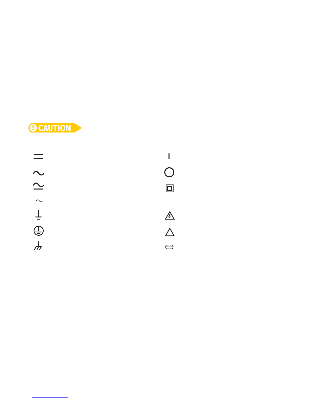
8 cHAPTER 1: Introduction
Direct current
Equipment protected throughout
by double insulation or reinforced
insulation (equivalent to Class II of
IEC 536—see Annex H)
CAUTION: risk of electric shock
!
CAUTION or WARNING: Refer to
instrument documentation
Off (supply)
On (supply)
Frame or chassis ground
Protective conductor terminal
Earth (ground) terminal
3
Three-phase alternating current
Both direct and alternating current
Alternating current
Fuse
Prevent Cooling Water Condensation
Do not operate the power supply when cooling
the dew point for local atmospheric conditions. Condensation on cooling water lines
inside the power supply can cause severe damage. Refer to section 2.5.4 for additional details.
Cleaning
Do not submerge instrument. Clean only with a damp cloth and mild detergent. Exterior only.
Moving and Handling
Casters are installed on the base to allow the unit to be rolled around. Four lifting lugs
provided for ease of moving and handling the Model 648. Always use all four lift-
are
ing lugs when lifting the unit. Because of its weight, the Model 648 should be handled
y mechanical means.
b
To avoid injury to personnel, always observe proper lifting techniques in accordance with
OSHA and other regulatory agencies.
water temperature is at or lower than
Model 648 Electromagnet Power Supply
FIGURE 1-2 Safety symbols
9
Chapter 2: Magnet System Design,
Installation, and Operation
2.1 General
2.2 Major
Components of the
Magnet
This chapter provides the user insight into the design, installation, and operation of a
typical electromagnet. For information on how to install the Model 648 please refer
to Chapter 3. For Model 648 operation information, refer to Chapter 4.
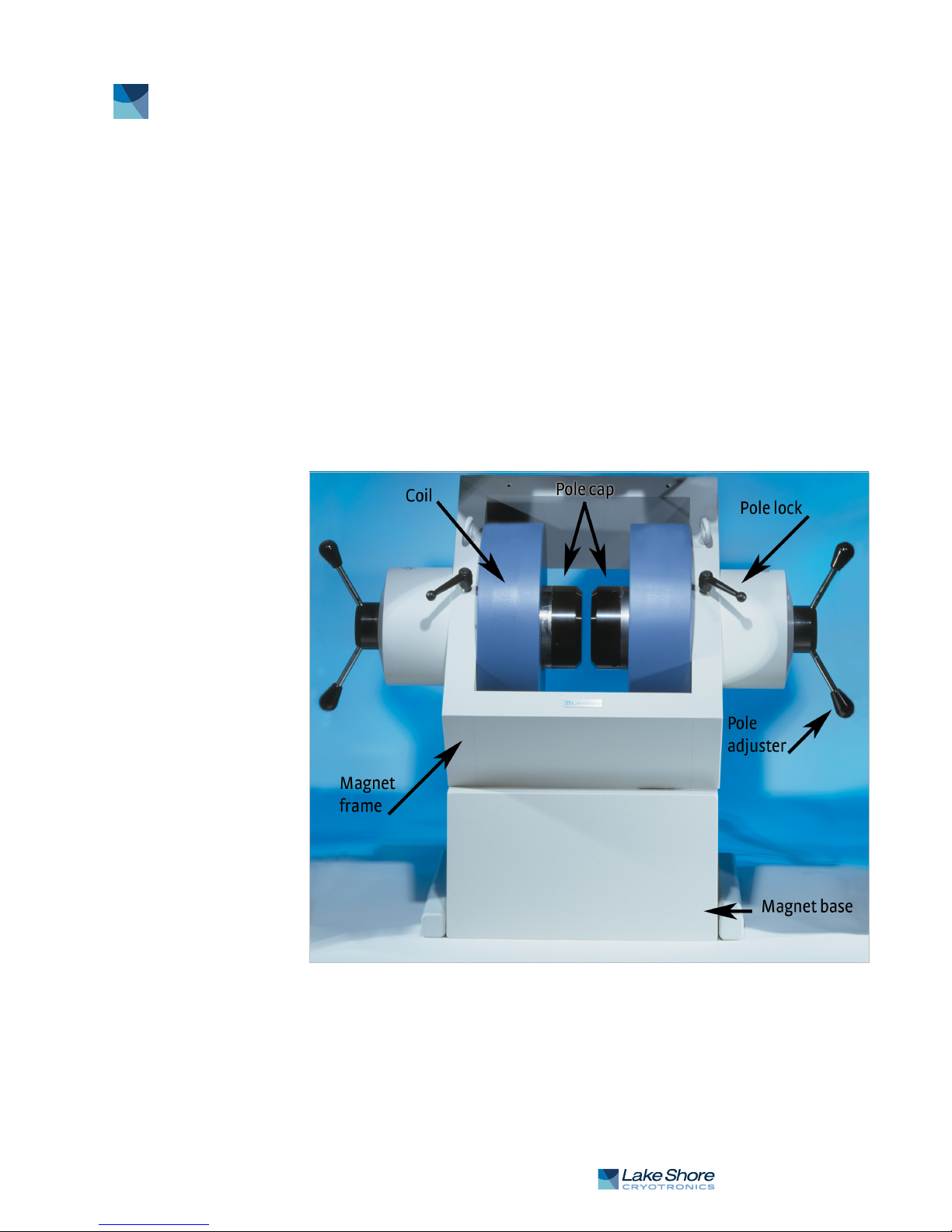
A magnet used with the Model 648 electromagnet power supply typically has an iron
pole, twin coil, 7 in or 10 in pole diameter, variable air gap, and is water cooled. Larger
magnets can be used depending on their electrical parameters and the magnetic field
requirements. The electromagnet provides a uniform magnetic field in the air gap
between two adjustable poles. The samples, which are to be tested for their magnetic
properties, are placed in the air gap with appropriate monitoring equipment
attached. By varying the polarity and intensity of the field, useful data can be
collected. A typical electromagnet is shown in FIGURE 2-1.
A typical electromagnetFIGURE 2-1
| www.lakeshore.com
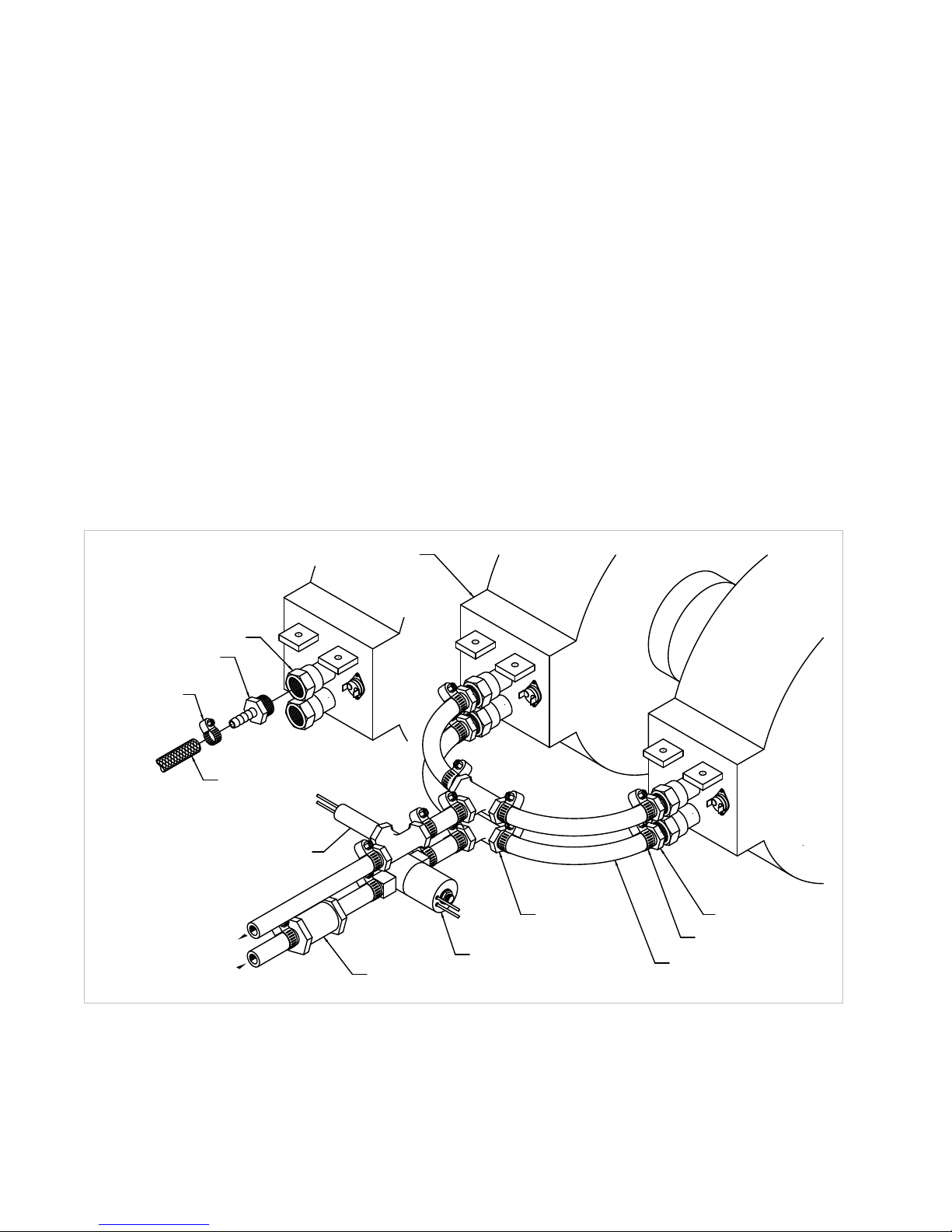
10 CHAPTER 2: Magnet System Design, Installation, and Operation
Reenforced hose
Optional water filter
Optional water valve
Te e
Optional flow switch
Magnet coil
Hose barb fitting
Hose clamp
Reenforced hose
Hose clamp
Hose barb fitting
Magnet water connection
2.3 Magnet
Construction
2.4 Connecting
the Magnet
2.4.1 Water Hose
Connection
The magnet consists of two water-cooled coils surrounding adjustable iron poles,
which are fitted into an iron frame. The frame supports the poles and coils, and
improves the magnet’s efficiency. The iron poles are fitted with adjusting
mechanisms so that the air gap width can be set. Lock mechanisms are provided to
hold the poles in place after adjustment is made. The poles faces have pole caps
attached, which provide the desired magnetic focus. The size and shape of the pole
caps are chosen according to the size of the sample being tested and the magnetic
field requirement.
Connecting the magnet to the power supply requires three separate circuits: the
cooling water hoses, the main high current power lines, and the safety switches.
These may include any combination of temperature and flow switches. These
connections are shown in FIGURE 2-2.
Water-cooling is essential for these magnets. The power dissipated can raise the
temperature of the coils to the point where they will be destroyed. In addition, the
samples being tested may exhibit changes in their magnetic performance with
changes in temperature causing errors in the collected data. Typical water
connection is shown in FIGURE 2-2. The magnets may be supplied with hose barbs or
standard hose fittings. The coils are conne
temperature rise is the same for both. Every effort should be made to insure that the
flow rate in both coils is the same. The minimum flow required is usually specified by
the magnet vendor.
cted in parallel so that the water
Model 648 Electromagnet Power Supply
FIGURE 2-2
Typical magnet water hook-up
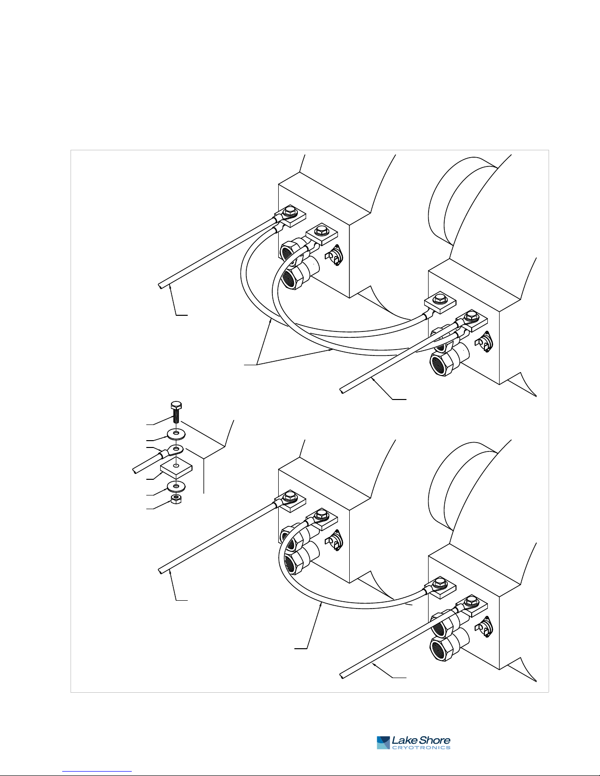
2 . 4 . 2 M a g n e t C o i l W i r i n g 11
Power lead
Power lead
Cross connection wiring
Power lead
Power lead
Cross connection wiring
Bolt
Belleville washer
Cable connection
Magnet power lug
Plain washer
Nut
-
+
-
+
-
+
-
+
(parallel wiring)
(series wiring)
2.4.2 Magnet Coil
Wiring
Typical magnet coil wiring is shown in FIGURE 2-3. The connecting cable used should
be of sufficient gage to prevent excessive voltage drop and heat rise in the cable. The
bles should be as short as possible to minimize the voltage drop. Current carrying
ca
capacities for various sizes of cables and cable lengths are shown in TABLE 3-3. The
connections must be made with the correct siz
We recommend the use of a spring or Belleville washer for cable terminations. When
the parts of a connection expand and contract with changes in temperature, they
tend to loosen. A spring washer will reduce this tendency.
e of hardware for the magnet terminal.
FIGURE 2-3
Typical magnet coil wiring showing series and parallel connections
| www.lakeshore.com
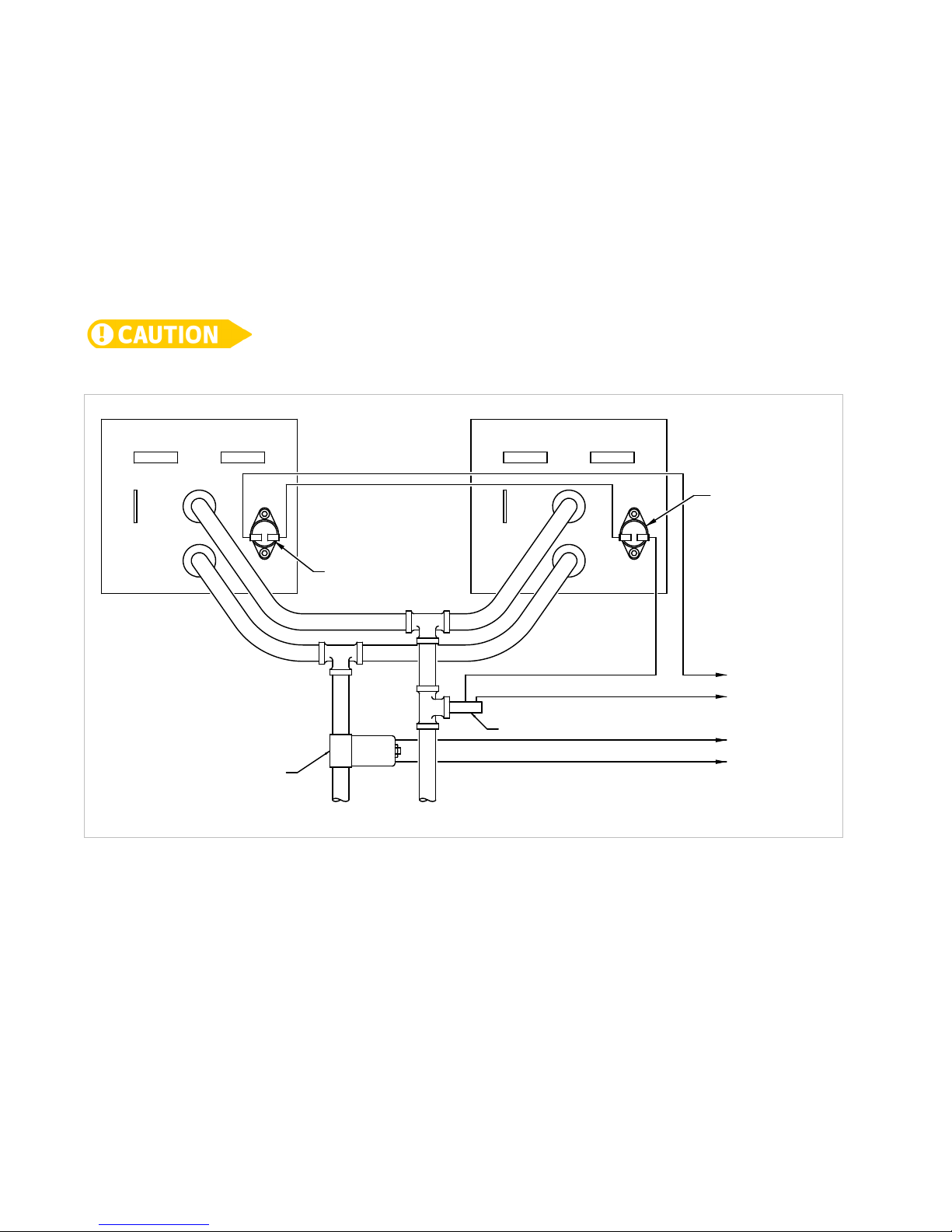
12 CHAPTER 2: Magnet System Design, Installation, and Operation
To Model 648 magnet connector valve contacts
To Model 648 magnet connector flow switch contacts
Inlet Outlet
Thermal switch
Flow switch
Water valve
Thermal switch
2.4.3 Temperature
Switches and Flow
Switches
As discussed in section 2.4.1, water-cooling for the magnet is essential. To protect the
magnet from damage resulting from an interruption in cooling water, a flow switch,
erature switches, or both should be installed. The switches must have a
temp
normally open contact (switch is open when no water is flowing), and if switches are
used, they must be connected in series. The switches are then connected to the flow
switch terminals of the magnet connector on the Model 648. The Model 648
monitors the switches and if an open is detected, the output current is ramped to
zero. (Flow switch monitoring depends on water valve mode setting. See section 4.13
and section 4.14 for details.) Given the cost of the magnet, it is prudent to use both
temperature and flow switches. Some install
ations use two flow switches, one in the
exhaust line of each coil so that if a clog occurs in only one coil, it can be detected.
FIGURE 2-4 shows the typical flow and temperature switch connection.
Care must be used in the selection of the flow switch. Some switches use a sensitive reed
switch, which can be overpowered by stray flux from the magnet and will not open when
the magnet is operating at high field. The flow switch must be tested by turning off the
water while the magnet is operating at full current.
FIGURE 2-4
2.4.4 Cooling Water
and Water Valve
The cooling water for the magnet can be drawn from the municipal water facility or
from a dedicated re-circulating water chiller designed for this purpose. When water is
drawn from the municipal water facility, the water should be turned on only when it
is required to reduce consumption and reduce the likelihood of scale build-up and
condensation in the magnet. The water can be turned on and off manually when the
magnet is used, or automatically with a solenoid valve. The Model 648 provides
automatic control and a 24 VAC at 1 A output for this purpose. The optional water
valve is shown in FIGURE 2-2. The water inlet line should also be fitted with a
sediment filter (not shown) to reduce scale build-up in the magnet coils and
ecting lines.
conn
Model 648 Electromagnet Power Supply
Typical thermal switch, flow switch and valve wiring

2 . 4 . 5 G r o u n d i n g 13
2.4.5 Grounding
2.4.6 Final Check-Out
2.5 Electromagnet
Operation
2.5.1 Air Gap and Pole
Caps
A ground connection (tapped hole) is usually available at the rear of the
electromagnet frame. This ground point is provided for customers who would like to
use the electromagnet frame as a signal ground or will be bringing hazardous live
voltages near the electromagnet and would like to make it an electrical safety
ground. Please verify suitability for such a function and compatibility with local and
national electrical codes before making ground connections. Scrape off excess paint
near the connecting screw to ensure a good electrical contact with the bare steel of
the electromagnet frame.
When all of the connections have been made, the system should be tested to be sure it
is operating correctly. The settings for the magnet water should be checked to verify
that they are correct for the configuration which has been installed (
The maximum current setting for the magnet should be set also (section 2.5.2 and
section 4.12.1).
This section provides a brief description of the typical operation of an electromagnet.
For operation of the Model 648, refer to Chapter 4.
The first step in setting up a magnet for operation is to select the proper pole caps and
adjust the air gap. These parameters are determined by the size and shape of the
sample, and the connections that must be made to the sample. Generally, a smaller
pole face provides a higher field within the air gap. A smaller air gap also provides a
higher field. The pole faces must be selected to accommodate the size of the sample
being tested. The air gap is selected based on the size of the sample and the other
equipment being used. The curves for field versus current for various air gaps and pole
cap sizes for the Lake Shore Model EM7-HVA are shown in
FIGURE 2-7. It also shows that these parameters are not linear. This must be taken
into account when operating an electromagnet. To obtain linearity, it is necessary to
operate the magnet and power supply under field control(
FIGURE 2-6 through
section 2.5.3).
section 4.13).
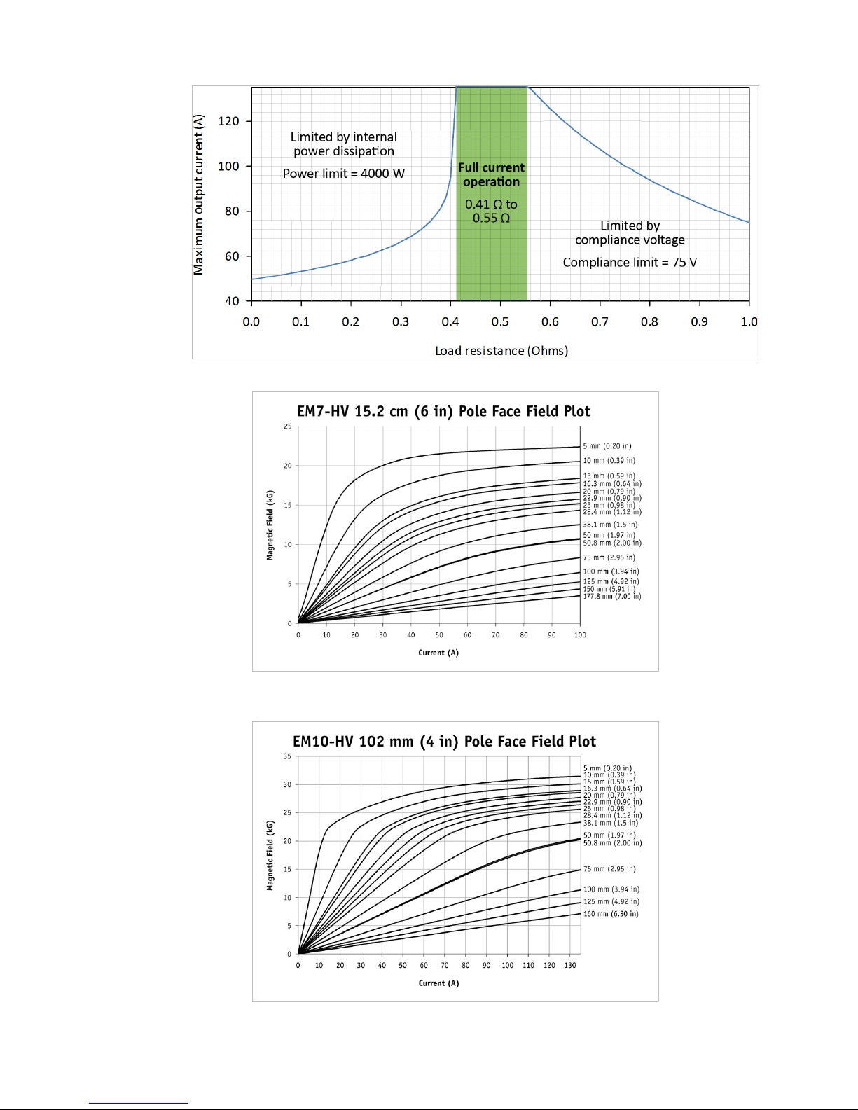
2.5.2 Maximum
Current and Power
The Model 648 was designed to operate with a magnet load resistance of 0.50 ), but
will provide full current output within a resistance range of 0.41 ) to 0.55 ). The
Model 648 will also work outside of the previously mentioned resistance range, but
will be limited by two factors: internal power dissipation and compliance voltage.
FIGURE 2-5 plots the maximum current output versus a resistance range of 0.00 ) to
1.00 ).
Also to be taken into account, the resistance of a magnet will rise with a rise in
temperature. The power dissipated in the magnet is given by: P = I
remains constant, the power dissipated will rise proportionately with the rise in
resistance.
2
R. If the current
| www.lakeshore.com
14 CHAPTER 2: Magnet System Design, Installation, and Operation
FIGURE 2-6
FIGURE 2-5
Maximum current output vs. resistance
Typical curves of field vs. current for 6 inch pole face on the EM7
FIGURE 2-7
Model 648 Electromagnet Power Supply
Typical curves of field vs. current for 4 inch pole face on the EM10

2 . 5 . 3 O p e r a t i o n U n d e r F i e l d C o n t r o l 15
2.5.3 Operation Under
Field Control
To obtain a linear field ramp, a magnetic sensor such as a Hall probe is placed in the
air gap along with the sample being tested. The sensor is connected to a gaussmeter.
The output of the gaussmeter is used to correct the programming input to the power
supply. In this way non-linearity can be corrected. Lakeshore manufactures probes
and gaussmeters for this purpose.
2.5.4 Avoiding Cooling
Water Condensation
If the temperature of the cooling water is too cool relative to the air temperature and
humidity, condensation can occur. Condensation inside the power supply can cause
severe damage. To avoid condensation, the power supply operator must remain
cognizant of the ambient air temperature, cooling water temperature, and the
relative humidity. Lake Shore defines the limits of these conditions as follows:
D a
mbient temperature = 18 - 28 °C (64 - 82 °F)
D cooling w
D humidity = 20
Knowing the actual state of these conditions, th
ater temperature = 15 - 25 °C (59 - 77 °F)
- 80% (non-condensing).
e operator can calculate the dew
point, or temperature at which condensation will occur. TABLE 2-1 and TABLE 2-2 are
included to aid in dew point calculation.
% Relative Humidit y
°C 100 95 90 85 80 75 70 65 60 55 50 45 40 35 30 25 20 15 10
32 32 31 31 29 28 27 26 24 23 22 20 18 17 15 12 9 6 2 0
29 29 28 27 27 26 24 23 22 21 19 18 16 14 12 10 7 3 0 —
27 27 26 25 24 23 22 21 19 18 17 15 13 12 10 7 4 2 0 —
24 24 23 22 21 20 19 18 17 16 14 13 11 9 7 5 2 0 — —
21 21 20 19 18 17 16 15 14 13 12 10 8 7 4 3 0 — — —
18 18 17 17 16 15 14 13 12 10 9 7 6 4 2 0 — — — —
16 16 14 14 13 12 11 10 9 7 6 5 3 2 0 — — — — —
TABLE 2-1
Dew point calculation (in degrees Celsius)
% Relative Humidit y
°F 100 95 90 85 80 75 70 65 60 55 50 45 40 35 30 25 20 15 10
90 90 88 87 85 83 81 79 76 74 71 68 65 52 59 54 49 43 36 32
85 85 83 81 80 78 76 74 72 69 67 64 61 58 54 50 45 38 32 —
80 80 78 77 75 73 71 69 67 65 62 59 56 53 50 45 40 35 32 —
75 75 73 72 70 68 66 64 62 60 58 55 52 49 45 41 36 32 — —
70 70 68 67 65 63 61 59 57 55 53 50 47 44 40 37 32 — — —
65 65 63 62 60 59 57 55 53 50 48 45 42 40 36 32 — — — —
60 60 58 57 55 53 52 50 48 45 43 41 38 35 32 — — — — —
TABLE 2-2
Dew point calculation (in degrees Fahrenheit)
Example: Determine the actual air temperature and relative humidity. Find the
closest air temperature in the left-hand column and the closest relative humidity
across the top. If the air temperature is 24 °C (75 °F) and the relative humidity is 35%,
the intersection of the two shows a dew point of 7 °C (45 °F). Therefore, for the given
conditions, the cooling water must remain above 7 °C (45 °F) to prevent
condensation.
| www.lakeshore.com

16 CHAPTER 2: Magnet System Design, Installation, and Operation
Model 648 Electromagnet Power Supply

17
Chapter 3: Installation
3.1 General
3.2 Inspection and
Unpacking
This chapter provides general installation instructions for the Model 648
electromagnet power supply.
To ensure the best possible performance and maintain operator safety, read this entire
chapter before installing the instrument and applying power. Serious hazards can exist
when an instrument of this power capacity is used incorrectly. If you do not understand
any section of this manual, consult Lake Shore for clarification. Lake Shore Cryotronics,
Inc. assumes no responsibility for damage or injuries incurred due to improper
installation, defeat of any of the safety features, or misuse of this power supply.
Inspect shipping containers for external damage before opening them. Photograph
any container that has significant damage before opening it. If there is visible damage
to the contents of the container, contact the shipping company and Lake Shore
immediately, preferably within five days of receipt of goods. Keep all damaged
shipping materials and contents until instructed to either return or discard them.
Open the shipping container and keep the container and shipping materials until all
ents have been accounted for. Check off each item on the packing list as it is
cont
unpacked. Instruments themselves may be shipped as several parts. The items
included with the Model 648 are described in the following list. Contact Lake Shore
immediately if there is a shortage of parts or accessories. Lake Shore is not
responsible for any missing items if not notified within 60 days of shipment.
Inspect all items for both visible and hidden
If damage is found, contact Lake Shore immediately for instructions on how to file a
proper insurance claim. Lake Shore products are insured against damage during
shipment, but a timely claim must be filed before Lake Shore will take further action.
Procedures vary slightly with shipping companies. Keep all shipping materials and
damaged contents until instructed to either return or discard them.
damage that occurred during shipment.
If the instrument must be returned for recalibration, replacement or repair, a
returned
representative prior to return. The Lake Shore RMA procedure is in section 6.12.2.
Items Included with the Model 648 electromagnet power supply:
D 1
D 1
D 1 analog I/O mating connect
D 1 s
D 1
D 1
D 2
D 1
D 2 h
D 1 output lug co
D Flow switch (shipped attached)
D 1 water ho
D 1 4
D 1 power cable
D 1 floo
goods authorization (RA) number must be obtained from a factory
Model 648 instrument
Model 648 User’s Manual
or
et of output terminal fasteners
wiring cover plate and screws (shipped attached)
2-pin detachable terminal block
4-pin detachable terminal blocks
8-pin detachable terminal block
ose clamps
ver and screws
se cover (shipped attached)
mm hex key
strain relief assembly
r mounting kit
| www.lakeshore.com
 Loading...