

Lakeshore 647 User Manual
USER'S MANUAL
Magnet Power Supply
Model 647
s
n
io
t
c
n
u
F
x
e
N
u
n
c
t
i
o
n
F
n
M
e
u
n
M
e
y
l
p
p
u
e
r
S
w
o
P
e
t
n
g
a
M
u
r
C
a
a
l
o
r
m
N
t
y
a
p
l
s
D
i
u
s
o
8
8
7
7
5
4
2
1
r
.
0
w
e
P
o
l
u
F
a
s
i
e
s
r
P
c
h
t
S
i
w
l
a
c
o
L
c
a
l
L
o
c
s
E
E
s
c
9
9
e
t
o
m
e
R
6
t
p
u
u
t
O
I
n
h
i
b
i
t
3
r
e
t
n
E
-
+
/
r
N
O
t
t
n
e
t
F
F
e
H
e
a
r
t
O
e
d
M
o
n
E
t
r
t
y
a
D
Lake Shore Cryotronics, Inc. • 575 McCorkle Blvd. • Westerville, OH 43082-8888
PH: 614-891-2243 • FAX: 614-891-1392
Internet Addresses: sales@lakeshore.com, service@lakeshore.com
Methods and apparatus disclosed and described herein have been developed solely on company funds of Lake Shore Cryotronics, Inc. No government or other contractual support or
relationship whatsoever has existed which in any way affects or mitigates proprietary rights of Lake Shore Cryotronics, Inc. in these developments. Methods and apparatus disclosed
herein may be subject to U.S. Patents existing or applied for. Lake Shore Cryotronics, Inc. reserves the right to add, improve, modify, or withdraw functions, design modifications, or
products at any time without notice. Lake Shore shall not be liable for errors contained herein or for incidental or consequential damages in connection with furnishing, performance, or
use of this material.
Rev. 1.0 19 January 1998

Lake Shore Model 647 Magnet Power Supply User’s Manual
MAGNET POWER SUPPLY CONFIGURATION
Sales Order Number: _______________________________ MPS Model Number:_____________________________
Shipping Date: ____________________________________ MPS Serial Number: _____________________________
Power Settings: ___________________________________________________________________________________
Below is a checklist of major options installed in your Model 622/633 Magnet Power Supply. Read the manual before
attempting to operate the equipment. 6224 IEEE-488/Serial Interface
6476 Gaussmeter Input Card
6477 High Resolution Display and Programming
Special Configurations:
________________________________________________________________________________________________
________________________________________________________________________________________________
________________________________________________________________________________________________
________________________________________________________________________________________________
LIMITED WARRANTY
Lake Shore Cryotronics, Inc. (henceforth Lake Shore), the manufacturer, warrants the instrument to be free from defects in
material and workmanship for a period of twelve months from the date of shipment. During the warranty period, under authorized
return of instruments or component parts to Lake Shore freight prepaid, the company will repair, or at its option replace, any part
found to be defective in material or workmanship, without charge to the Owner for parts, service labor or associated customary
shipping cost. Replacement or repaired parts will be warranted for only the unexpired portion of the original warranty.
All products are thoroughly tested and calibrated to published specifications prior to shipment. Calibration Certifications are
offered for six month periods only. Where such documentation must be updated, a re-certification service is offered by Lake
Shore at a reasonable cost.
LIMITATION OF WARRANTY: This warranty is limited to Lake Shore products purchased and installed in the United States, or
Internationally through our approved distribution agents. This same protection will extend to any subsequent owner during the
warranty period. It does not apply to damage resulting from improper or inadequate maintenance, unauthorized modification or
misuse, operation outside of the environmental specifications, or from buyer-supplied software interfacing. It does not apply to
damage caused by accident, misuse, fire, flood or Acts of God, or from failure to properly install, operate, or maintain the product
in accordance with the printed instruction provided.
This warranty is in lieu of any other warranties, expressed or implied, including merchantability or fitness for a particular purpose,
which are expressly excluded. the owner agrees that Lake Shore’s liability with respect to this product shall be set forth in this
warranty, and incidental or consequential damages are expressly excluded.
CERTIFICATION: Lake Shore certifies that this product has been inspected and tested in accordance with its published
specifications and that this product met its published specifications at the time of shipment. The accuracy and calibration of this
product at the time of shipment are traceable to the United States National Institute of Standards and Technology (NIST);
formerly known as the National Bureau of Standards (NBS), or to a recognized natural standard.
TRADEMARK ACKNOWLEDGMENT: Many manufacturers and sellers claim designations as trademarks to distinguish their
products. Where those designations appear in this manual and Lake Shore was aware of a trademark claim, they appear with
initial capital letters and a proceeding ™ or
CalCurve™, Carbon-Glass™, Cernox™, Duo-Twist™, IDEA™, Gamma Probe™, Quad-Lead™,
and Quad-Twist™ are trademarks of Lake Shore Cryotronics, Inc.
®
Kapton
Stycast® is a trademark of Emerson & Cuming.
Teflon® is a trademark of DuPont De Nemours.
QuickBasic® is a trademark of Microsoft Corporation.
Copyright © 1995 - 1998 by Lake Shore Cryotronics, Inc. All rights reserved. No portion of this manual may be reproduced, stored in a retrieval system, or transmitted, in
any form or by any means, electronic, mechanical, photocopying, recording, or otherwise, without the express written permission of Lake Shore.
is a trademark of 3M.
®
symbol.
A

Lake Shore Model 647 Magnet Power Supply User’s Manual
TABLE OF CONTENTS
Chapter/Paragraph Title Page
List of Illustrations............................................................................................................................ iv
List of Tables ................................................................................................................................... iv
Foreword ........................................................................................................................................ v
Purpose and Scope .................................................................................................................. v
Hardware Covered.................................................................................................................... v
How To Use This Manual.......................................................................................................... v
Warnings, Cautions, and Notes ................................................................................................ v
General Installation Precautions............................................................................................... v
Electrostatic Discharge ............................................................................................................. vi
Handling Electrostatic Discharge Sensitive Components ......................................................... vi
Safe Handling of Liquid Cryogens............................................................................................. vi
Magnet Quenches ..................................................................................................................... vii
Dangerous Voltages ................................................................................................................. vii
Before You Operate the Equipment .......................................................................................... vii
Safety Summary........................................................................................................................ viii
Safety Symbols ......................................................................................................................... viii
1 INTRODUCTION ............................................................................................................................. 1-1
1.0 General............................................................................................................................ 1-1
1.1 647 Magnet Power Supply Features............................................................................... 1-1
1.2 Specifications .................................................................................................................. 1-2
1.3 Operating Characteristics ............................................................................................... 1-4
1.3.1 True, Four-Quadrant Bidirectional Power Flow .............................................................. 1-4
1.3.2 Low Noise, High Stability Current Regulated Output...................................................... 1-5
1.3.3 Highly Efficient, Air-Cooled, Compact Unit ..................................................................... 1-5
2 INITIAL SETUP AND CONNECTIONS .......................................................................................... 2-1
2.1 Inspecting and Unpacking............................................................................................... 2-1
2.2 MPS Mounting................................................................................................................. 2-1
2.3 Environmental Requirements.......................................................................................... 2-1
2.4 Connecting the MPS to Power ........................................................................................ 2-2
2.4.1 Power and Ground Requirements .................................................................................. 2-2
2.4.2 MPS Input Power Ratings............................................................................................... 2-2
2.4.3 Input Power Connections................................................................................................ 2-2
2.5 Power Up......................................................................................................................... 2-3
2.5.1 Magnet Cable Connections............................................................................................. 2-3
2.5.2 Shielding, Grounding, and Noise .................................................................................... 2-4
2.5.3 MPS Remote Inhibit and Fault Indicator Connections .................................................... 2-4
2.5.4 AC On Indicator............................................................................................................... 2-4
2.5.5 OVP Connection ............................................................................................................. 2-4
2.5.6 MPS Analog Current and Voltage Monitoring Connections............................................ 2-5
2.5.7 External Current Programming ....................................................................................... 2-5
2.5.8 Remote Sense Connections ........................................................................................... 2-6
2.6 Multiple Auto-Parallel Setup............................................................................................ 2-6
2.7 Post-Installation Instructions ........................................................................................... 2-9
2.8 System Shutdown and Repackaging for Storage or Shipment ...................................... 2-9
2.9 Returning Equipment to Lake Shore............................................................................... 2-9
Table of Contents
i

Lake Shore Model 647 Magnet Power Supply User’s Manual
Chapter/Paragraph Title Page
3 OPERATION................................................................................................................................... 3-1
3.0 General ........................................................................................................................... 3-1
3.1 The MPS Front Panel ..................................................................................................... 3-1
3.2 Power UP........................................................................................................................ 3-1
3.3 General Display Description ........................................................................................... 3-2
3.4 Numeric Entry ................................................................................................................. 3-2
3.5 Function Menu 1 ............................................................................................................. 3-2
3.5.1 Setup Screen .................................................................................................................. 3-2
3.5.2 Output Only Screen ........................................................................................................ 3-3
3.5.3 Display Plot Screen ........................................................................................................ 3-3
3.5.4 Ramp Status Screen ...................................................................................................... 3-3
3.6 Function Menu 2 ............................................................................................................. 3-3
3.7 Function Menu 3 ............................................................................................................. 3-4
3.7.1 Current Zero Screen....................................................................................................... 3-4
3.7.2 Current Step Limit Screen .............................................................................................. 3-4
4 REMOTE OPERATION .................................................................................................................. 4-1
4.0 General ........................................................................................................................... 4-1
4.1 IEEE-488 Interface ......................................................................................................... 4-1
4.1.1 IEEE-488 Interface Settings ........................................................................................... 4-1
4.1.2 IEEE-488 Command Structure ....................................................................................... 4-2
4.1.2.1 Bus Control Commands ................................................................................................. 4-2
4.1.2.2 Common Commands...................................................................................................... 4-2
4.1.2.3 Interface and Device Specific Commands ..................................................................... 4-2
4.1.3 Status Registers ............................................................................................................. 4-2
4.1.3.1 Status Byte and Service Request Enable Registers ...................................................... 4-3
4.1.3.2 Standard Event and Standard Event Status Registers .................................................. 4-4
4.1.4 Example IEEE Setup and Program ................................................................................ 4-4
4.1.4.1 GPIB Board Installation .................................................................................................. 4-4
4.1.4.2 Run the Example QuickBasic Program .......................................................................... 4-5
4.1.5 Notes On Using the IEEE Interface ................................................................................ 4-5
4.2 Serial I/O Interface.......................................................................................................... 4-8
4.2.1 Serial Interface Hardware Configuration ....................................................................... 4-9
4.2.2 Serial Interface Settings ................................................................................................. 4-9
4.2.3 Sample BASIC Serial Interface Program ....................................................................... 4-9
4.2.4 Notes on Using the Serial Interface................................................................................ 4-9
4.3 Summary of IEEE-488/Serial Interface Commands ....................................................... 4-11
4.3.1 Commands Description List Structure............................................................................ 4-11
4.3.1.1 Operational Commands Description .............................................................................. 4-12
4.3.1.2 Interface Commands Description ................................................................................... 4-14
4.3.1.3 Ramping Commands Description................................................................................... 4-15
4.3.1.4 Current Zero Commands Description............................................................................. 4-16
4.3.1.5 Current Step Limit Commands Description .................................................................... 4-17
4.3.1.6 Common Commands Description .................................................................................. 4-18
5 ERROR MESSAGES AND TROUBLESHOOTING ....................................................................... 5-1
5.0 General ........................................................................................................................... 5-1
5.1 Software Error Messages ............................................................................................... 5-1
5.2 Factory Default Settings ................................................................................................. 5-3
5.3 Calibration....................................................................................................................... 5-4
5.4 Performance Test ........................................................................................................... 5-5
5.5 Rear Panel Connector Details ........................................................................................ 5-6
5.6 IEEE-488 Interface Connector (If Present)..................................................................... 5-7
5.7 Serial Interface Cable and Adapters .............................................................................. 5-7
ii
Table of Contents

Lake Shore Model 647 Magnet Power Supply User’s Manual
Chapter/Paragraph Title Page
6 OPTIONS AND ACCESSORIES .................................................................................................... 6-1
6.0 General............................................................................................................................ 6-1
6.1 Model 6224 IEEE-488/Serial Interface............................................................................ 6-1
6.2 Model 6476 Gaussmeter Input Card ............................................................................... 6-1
6.2.1 Hall Sensor Mounting Considerations ............................................................................ 6-1
6.2.2 Connections .................................................................................................................... 6-2
6.2.3 Installation ....................................................................................................................... 6-2
6.2.4 Operation......................................................................................................................... 6-3
6.2.5 Remote Operation Commands ....................................................................................... 6-3
6.3 Model 6477 High Resolution Display and Programming Option .................................... 6-4
6.4 Accessories..................................................................................................................... 6-5
APPENDIX A – UNITS FOR MAGNETIC PROPERTIES ................................................................... A-1
APPENDIX B – MAINFRAME REMOTE OPERATION ...................................................................... B-1
B1.0 General............................................................................................................................ B-1
B2.0 Control Bus Serial Interface Specifications..................................................................... B-1
B3.0 Control Bus Serial Interface Connector .......................................................................... B-1
B4.0 Control Bus Serial Interface Configuration ..................................................................... B-2
B5.0 Selecting the Control Bus Serial Interface Address........................................................ B-2
B6.0 Control Bus Serial Interface Operation ........................................................................... B-3
B7.0 Control Bus Serial Interface Sample Program................................................................ B-4
Table of Contents
iii

Lake Shore Model 647 Magnet Power Supply User’s Manual
LIST OF ILLUSTRATIONS
Figure No. Title Page
1-1 Four-Quadrant Power ..................................................................................................................... 1-4
1-2 Comparison of Old and New MPS Designs.................................................................................... 1-5
2-2 RI, FLT, ON, and OVP Connections............................................................................................... 2-4
2-3 Analog Monitoring, Programming, & Remote Sense Connections................................................. 2-5
2-4 Remote Sensing Connections ........................................................................................................ 2-6
2-5 Typical Multiple MPS Connections for Two MPS Units .................................................................. 2-8
3-1 Front Panel Numeric Entry Keys..................................................................................................... 3-1
4-1 Typical National Instruments GPIB Configuration from IBCONF.EXE ........................................... 4-7
4-2 Serial Interface Adapters ................................................................................................................ 4-8
5-1 Rear Panel Connectors................................................................................................................... 5-6
5-2 Serial Interface Connector .............................................................................................................. 5-6
5-3 IEEE-488 Connector ....................................................................................................................... 5-7
5-4 Model 2001 RJ-11 Cable Assembly Wiring .................................................................................... 5-7
5-5 Model 2002 RJ-11 to DB-9 Adapter Wiring .................................................................................... 5-7
5-6 Model 2003 RJ-11 to DB-25 Adapter Wiring .................................................................................. 5-7
LIST OF TABLES
Table No. Title Page
1-1 Model 647 DC Output Specifications.............................................................................................. 1-3
2-1 MPS Line Voltage Limits................................................................................................................. 2-2
2-2 Load Wire Lengths and Current Capacity....................................................................................... 2-3
2-3 RI, FLT, ON, and OVP Connections............................................................................................... 2-4
2-4 Analog Monitoring, Programming, and Remote Sense Connections ............................................. 2-5
2-5 Connections for a Two-MPS Autoparallel Configuration ................................................................ 2-8
4-1 Sample Basic IEEE-488 Interface Program.................................................................................... 4-6
4-2 Serial Interface Specifications......................................................................................................... 4-9
4-3 Sample Basic Serial Interface Program.......................................................................................... 4-10
5-1 Rear Panel Connector Definitions................................................................................................... 5-6
5-2 Serial Interface Connector Definition.............................................................................................. 5-6
5-3 IEEE-488 Interface Connector Definition........................................................................................ 5-7
A-1 Units for Magnetic Properties.......................................................................................................... A-1
B-1 MPS Mainframe Control Bus Remote Command Summary .......................................................... B-5
B-2 Additional MPS Mainframe Control Bus Remote Commands ........................................................ B-6
iv
Table of Contents

Lake Shore Model 647 Magnet Power Supply User’s Manual
FOREWORD
PURPOSE AND SCOPE
This manual contains user instructions for the Model 647 Superconducting Magnet Power Supply. Lake
Shore Cryotronics, Inc. designed, manufactures, and assembles the MPS in the United States of America.
We welcome your comments concerning this manual. Although every effort has been made to keep it free of
errors, some may occur. To report a specific problem, please describe it briefly and include the manual title
and revision number, the paragraph/figure/table number, and the page number. Send comments to Lake
Shore Cryotronics, Inc. Attn: Technical Publications, 575 McCorkle Blvd., Westerville, Ohio 43082-8888.
HARDWARE COVERED
The MPS is available in the following configuration:
Model 647 Electromagnet Power Supply: ±72 A, ±32 V, 2 kVA
Page A of this manual (following the title page) details the options installed in your unit. See chapter 6
for detailed definitions of hardware configurations.
WARNINGS, CAUTIONS, AND NOTES
Warnings, cautions, and notes appear throughout this manual and always precede the step to which they
pertain. Multiple warnings, cautions, or notes are bulleted.
WARNING: An operation or maintenance procedure which, if not strictly observed, may result in
injury, death, or long-term health hazards to personnel.
CAUTION: An operation or maintenance procedure which, if not strictly observed, may result in
equipment damage, destruction, or loss of effectiveness.
NOTE: Emphasizes an operation or maintenance procedure.
GENERAL INSTALLATION PRECAUTIONS
These recommended general safety precautions are unrelated to any specific procedure and do not appear
elsewhere in this manual. Personnel should understand and apply these precautions during installation.
Installation personnel shall observe all safety regulations at all times. Keep away from live circuits. Turn off
system power before making or breaking electrical connections. Regard any exposed connector, terminal
board, or circuit board as a possible shock hazard. Discharge charged components only when such
grounding cannot damage equipment. If a test connection to energized equipment is required, make the test
equipment ground connection before probing the voltage or signal.
Do not install or service equipment alone. Do not under any circumstances reach into or enter any enclosure
to service or adjust equipment without the presence or assistance of another person able to render aid.
Forward
v
Lake Shore Model 647 Magnet Power Supply User’s Manual
ELECTROSTATIC DISCHARGE
Electrostatic Discharge (ESD) may damage electronic parts, assemblies, and equipment. ESD is a transfer of
electrostatic charge between bodies at different electrostatic potentials caused by direct contact or induced by
an electrostatic field. The low-energy source that most commonly destroys Electrostatic Discharge Sensitive
(ESDS) devices is the human body, which generates and retains static electricity. Simply walking across a
carpet in low humidity may generate up to 35,000 volts of static electricity.
Current technology trends toward greater complexity, increased packaging density, and thinner dielectrics
between active elements, which results in electronic devices with even more ESD sensitivity. Some electronic
parts are more ESDS than others. ESD levels of only a few hundred volts may damage electronic
components such as semiconductors, thick and thin film resistors, and piezoelectric crystals during testing,
handling, repair, or assembly. Discharge voltages below 4000 volts cannot be seen, felt, or heard.
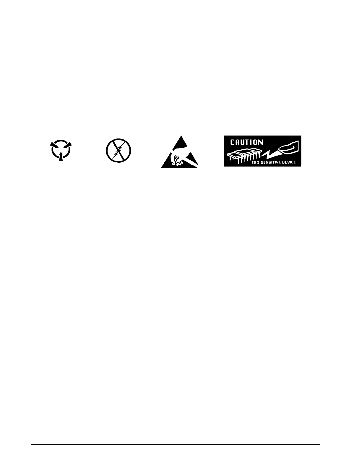
Identification of Electrostatic Discharge Sensitive Components
Below are various industry symbols used to label components as ESDS:
HANDLING ELECTROSTATIC DISCHARGE SENSITIVE COMPONENTS
Observe all precautions necessary to prevent damage to ESDS components before attempting installation.
Bring the device and everything that contacts it to ground potential by providing a conductive surface and
discharge paths. As a minimum, observe these precautions:
1. De-energize or disconnect all power and signal sources and loads used with unit.
2. Place unit on a grounded conductive work surface.
3. Ground technician through a conductive wrist strap (or other device) using 1 MΩ series resistor to protect
operator.
4. Ground any tools, such as soldering equipment, that will contact unit. Contact with operator's hands
provides a sufficient ground for tools that are otherwise electrically isolated.
5. Place ESDS devices and assemblies removed from a unit on a conductive work surface or in a
conductive container. An operator inserting or removing a device or assembly from a container must
maintain contact with a conductive portion of the container. Use only plastic bags approved for storage of
ESD material.
6. Do not handle ESDS devices unnecessarily or remove them from their packages until actually used or
tested.
SAFE HANDLING OF LIQUID CRYOGENS
Two essential safety aspects of handling LHe are adequate ventilation and eye and skin protection. Although
helium gas is non-toxic, it is dangerous because it replaces air in a normal breathing atmosphere. Liquid
helium is an even greater threat because a small amount of liquid evaporates to create a large amount of
gas. Store and operate cryogenic dewars in open, well-ventilated areas.
WARNING
• Liquid helium is a potential asphyxiant and can cause rapid suffocation without warning. Store
and use in an adequately ventilated area. DO NOT vent the container in confined spaces. DO NOT
enter confined spaces where gas may be present unless area is well-ventilated. If inhaled, remove
to fresh air. If not breathing, give artificial respiration. If breathing is difficult, give oxygen. Get
medical attention.
• Liquid helium can cause severe frostbite to exposed body parts. DO NOT touch frosted pipes or
valves. For frostbite, consult a physician immediately. If a physician is unavailable, warm the
affected parts with water that is near body temperature.
vi
Forward

Lake Shore Model 647 Magnet Power Supply User’s Manual
MAGNET QUENCHES
For protection during a magnet quench, fit the dewar with pressure relief valves of sufficient size and
pressure rating to allow the helium gas to escape and to prevent excessive pressure in the dewar. Operating
a magnet in a dewar without proper pressure relief is dangerous and possibly life-threatening. The magnet
may transfer tremendous energy to the cryogen during a quench. Consult both the magnet and dewar
manufacturers to check pressure relief valve sufficiency.
DANGEROUS VOLTAGES
High voltages are present inside the MPS. Never attempt to service the MPS. Refer all service to qualified
personnel. There are no user-serviceable parts inside the MPS.
The MPS current output terminals may be dangerous. Although MPS output voltage is limited to ±40 VDC, a
catastrophic failure inside the MPS could pass lethal voltages to the output terminals. Do not touch the
terminals during MPS operation.
BEFORE YOU OPERATE THE EQUIPMENT
Train personnel in proper emergency measures such as electrical power shut off, fire department notification,
fire extinguishing, and personnel and records evacuation. Here is a list of suggested personnel safety
considerations:
• Ground Fault Interrupter (GFI) AC circuits
• Fire Extinguisher
• Magnetic Field Warnings
• Emergency Lighting
Locate in the immediate vicinity fire extinguisher(s) that extinguish all three classes of fires: A, B, and C.
Class A is ordinary combustibles like wood, paper, rubber, many plastics, and other common materials that
burn easily. Class B is flammable liquids like gasoline, oil, and grease. Class C is energized electrical
equipment including wiring fuse boxes, circuit breakers, machinery, and appliances. Do not use chemical
extinguishers even though they are less expensive and cover all classes of fires. They may damage
electronic equipment. Use a Carbon Dioxide or Halon fire extinguisher.
During the planning stage, consult local experts, building authorities, and insurance underwriters on locating
and installing sprinkler heads, fire and smoke sensing devices, and other fire extinguishing equipment.
Even where not required by code, install some type of automatic, battery-operated emergency lighting in case
of power failure or fire.
Forward
vii
Lake Shore Model 647 Magnet Power Supply User’s Manual
SAFETY SUMMARY
Observe the following general safety precautions during all phases of operation, service, and repair of this
instrument. Failure to comply with these precautions or with specific warnings elsewhere in this manual
violates safety standards of design, manufacture, and intended use of the instrument. Lake Shore
Cryotronics, Inc. assumes no liability for the customer's failure to comply with these requirements.
Ground the Instrument
To minimize shock hazard, connect the instrument chassis and cabinet to an electrical ground. The
instrument is equipped with a three-conductor AC power cable. Plug this cable into either an approved threecontact electrical outlet or a three-contact adapter with the grounding wire (green) firmly connected to an
electrical ground (safety ground) at the power outlet. The power jack and mating plug of the power cable
meet Underwriters Laboratories (UL) and International Electrotechnical Commission (IEC) safety standards.
Do Not Operate in an Explosive Atmosphere
Do not operate the instrument in the presence of flammable gases or fumes. Operating any electrical
instrument in such an environment constitutes a definite safety hazard.
Keep Away from Live Circuits
Operating personnel must not remove instrument covers. Refer component replacement and internal
adjustments to qualified maintenance personnel. Do not replace components with power cable connected. To
avoid injuries, always disconnect power and discharge circuits before touching them.
Do Not Substitute Parts or Modify Instrument
Do not install substitute parts or perform any unauthorized modification to the instrument. Return the
instrument to an authorized Lake Shore Cryotronics, Inc. representative for service and repair to ensure that
safety features are maintained.
Dangerous Procedure Warnings
A WARNING heading precedes potentially dangerous procedures throughout this manual. Instructions in the
warnings must be followed.
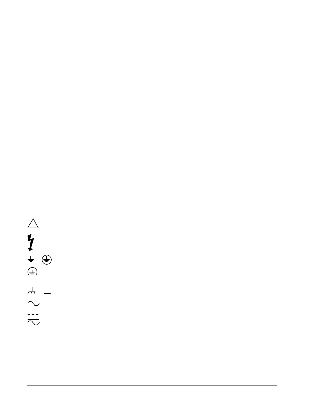
SAFETY SYMBOLS
!
Warns to protect the instrument against damage.
Indicates dangerous voltage (appears on terminals fed by voltage exceeding 1000 volts).
Protective conductor terminal. For protection against electrical shock in case of a fault. Used with
or
field wiring terminals to indicate the terminal to connect to ground before operating equipment.
Low-noise or noiseless, clean ground (earth) terminal. Provides a signal common as well as
protection against electrical shock in case of a fault. Connect a terminal marked with this
symbol to ground as described in the user manual before operating equipment.
Frame or chassis terminal. A connection to the frame (chassis) of the equipment which normally
or
includes all exposed metal structures.
Alternating current (power line).
Direct current (power line).
Alternating or direct current (power line).
viii
Forward

Lake Shore Model 647 Magnet Power Supply User’s Manual
CHAPTER 1
INTRODUCTION
1.0 GENERAL
This chapter covers Features (Paragraph 1.1), Specifications (Paragraph 1.2), and Operating Characteristics
(Paragraph 1.3).
1.1 647 MAGNET POWER SUPPLY FEATURES
• True, Four-Quadrant Bidirectional Power Flow
Operate current or voltage as a source or a sink in either positive or negative polarities. Sink power returns
to the AC line instead of dissipating through an energy absorber.
• Low Noise, High Stability Current Regulation
Analog output control uses a precision shunt for current stabilization to better than 50 PPM of full-scale
current over an 8-hour period.
• ±72 A, ±32 V Output that is Autoranging at up to 2 kVA continuous
Standard display and programming resolution is 10 mA and 10 mV. 1 mA and 1 mV High Resolution
Option is available.
• No current reversal switch is required
Output current reversal is smooth and continuous with excellent near zero current performance.
• Remote and local sensing of the output voltage
Compensates for voltage drops in the output leads.
• Quiet switched-mode design
Results in a highly efficient, lightweight, air-cooled unit.
• Front Panel Graphic Display
Allows continuous display of output while setting parameters from the menu-driven keypad. Operating
parameters that can be set and monitored are:
1. Output current and voltage setting
2. Output current and voltage measurement
3. Output current step limiting
4. Output current zeroing
5. "Soft" current and voltage setting limits
6. Output ramp programming
7. Status reporting
8. Field monitoring (with optional Model 6476 Card)
• Four methods of setting and monitoring all operating parameters:
1. From front panel
2. From remote interfaces
3. Through analog inputs and outputs
• IEEE-488 Interface available.
• Gaussmeter Input Option available.
• Protection
Overvoltage/Quench protection circuits protect against internal overtemperature, AC line fault, and unit
fault. Also includes a Remote Inhibit (RI) and a discrete Fault Indicator (FLT).
Introduction
1-1

Lake Shore Model 647 Magnet Power Supply User’s Manual
1.2 SPECIFICATIONS
Below are performance specifications for current with a 1 Henry load and voltage with a resistive load.
DC Output: True, Four-Quadrant, Bidirectional Power Flow output. Autoranging current and voltage operate
as a source or a sink in either polarity in current or voltage mode. Program current and voltage via the front
panel, remote interfaces, or analog input. See Table 1-1 for DC Output Specifications.
Current: 0 to ±72 A Voltage: 0 to ±32 V Maximum Power: 2 kVA continuous
Remote Sensing: Corrects for load lead drop of up to 0.5 V per lead. Operation with more drop per load lead
is possible with a degradation of the load effect specification.
Output Terminals: The two rear panel output bus bars are isolated from the chassis (earth) ground.
Multiple Unit Operation: Connect up to four units in an auto-parallel configuration for increased output current.
Protection: Front panel annunciators, an audio indicator, and a contact closure indicate faults.
Remote Inhibit (RI): An active RI forces output settings to 0 A and 1 V until the RI is no longer active. To
continue normal operation, enter new output settings.
Output Inhibit (OI): Press the front panel OI key to force output settings to 0 A and 1 V. To continue normal
operation, enter new output settings.
Output Current Step Limit: The output current settings are forced to 0 A and 1 V if a preset current step limit
is exceeded. A key entry is required to continue operation.
Utility Low Line or Loss: Maintains operation until load is discharged or utility is restored.
Utility High Line: Turns off input and maintains operation until load is discharged.
Overvoltage: Crowbars output when output terminal voltage, induced by the load exceeds ±40 VDC.
Overtemperature: Crowbars output and turns off input when internal heat sink temperature exceeds 95 °C.
AC Input: Factory set for operation from 200, 208, 220, or 240 VAC (–10%, +5%), 50 to 60 Hz, single phase.
Input Protection: A front panel 20 A two-pole circuit breaker protects the AC input. The MPS turns off the
breaker in the event of a fault.
Remote Interfaces: RS-232C is standard; IEEE-488 is optional. All front panel functions can be controlled
over the interfaces. In addition, interfaces output displayed quantities.
Input Current:
Nominal Line
Voltage (VAC)
Line Voltage
Range (VAC)
200 180 to 210 16
208 188 to 218 15
220 198 to 231 14
240 216 to 250 13
Maximum Input
Current (A rms)
Front Panel: Contains a menu driven keyboard and graphic display for entry and display of results. Operating
parameters to set and monitor from the front panel (and remote interface) include:
• Output current and voltage setting
• Output current and voltage measurement
• Status reporting
• Output ramp programming
• "Soft" current and voltage setting limits
• Field Monitoring (with optional Model 6476 Card)
• Output Current Zeroing
• Output Current Step Limiting
Magnet inductance and maximum charging voltage (di/dt = V/L) limit the output ramp programming charging
current. Program output for a constant 0.01 to 99.99 amperes per second as long as di
/dt is not exceeded.
max
Energize or de-energize the magnet at a pre-set voltage limit or ramp rate. Pause the ramp at any time during
the ramp. During a pause, the MPS maintains output values until the ramp continues.
1-2
Introduction

Lake Shore Model 647 Magnet Power Supply User’s Manual
Agency Approvals: The Model 647 complies with the following requirements:
UL 1244 - Electrical and Electronic Measuring and Testing Equipment
VDE 0411 - Electronic Measuring Instruments and Automatic Controls
FCC 15J - Level A RFI Suppression
VDE 0871 - Level A RFI Suppression
Operating Ambient Temperature: 15 to 35 °C (59 to 95 °F)
Dimensions: 483 mm wide x 178 mm high x 508 mm deep (19 x 7 x 20 inches)
Weight: 36.4 kilograms (80 pounds). Rack mounting is standard.
Table 1-1 Model 647 DC Output Specifications
SPECIFICATION CURRENT VOLTAGE
Digital Programming Resolution:
Standard/High
Digital Programming Accuracy
Digital Programming Repeatability
Electronic Resolution:
Standard/High
Electronic Accuracy
Display Resolution: Standard/High
Stability (Drift) at 25 ±1 °C: Percent of full scale
output change over 8-hours under constant line and load after
a 30 minute warm-up.
Ripple and Noise: 10 Hz to 10 MHz at 1000 VA
Temperature Coefficient: Change in output per °C
after 30 minute warm-up.
Source Effect: Line regulation for any line change within
the rated line voltage.
Load Effect: Load regulation for a load change equal to
maximum voltage in Constant Current Mode or maximum
current in Constant Voltage Mode.
Analog Resistance Programming Accuracy:
0 to 10 KΩ produces negative full scale to positive full scale
current or voltage output. 5 KΩ is 0 current.
Analog Voltage Programming Accuracy:
Voltage input is ±0.01 V/A, ±0.01 V/V.
Monitoring Output Accuracy: Voltage output is
±0.01 V/A, ±0.01 V/V.
10 mA / 1 mA 10 mV / 1 mV
0.1% IMAX
0.01% IMAX
4 mA / 1 mA 1 mV / 1 mV
0.1% IMAX
10 mA / 1 mA 10 mV / 1 mV
±0.005% I
MAX
40 µA rms 20 mV rms
0.1% I
MAX
0.005% I
0.1% I
1% + 100 mA
1% + 100 mA
10% I
MAX
MAX
MAX
MAX
1% V
0.1% V
0.1% V
±0.01% V
0.1% V
0.05% V
0.1% V
10% V
MAX
MAX
MAX
MAX
MAX
MAX
MAX
2% + 100 mV
2% + 100 mV
Introduction
1-3
Lake Shore Model 647 Magnet Power Supply User’s Manual
1.3 OPERATING CHARACTERISTICS
Many Model 647 MPS operating characteristics ideally suit it for charge and discharge cycling of
superconducting magnet loads. These characteristics significantly differentiate the Model 647 from
conventional MPS's. Consider them when choosing the best MPS for a particular application.
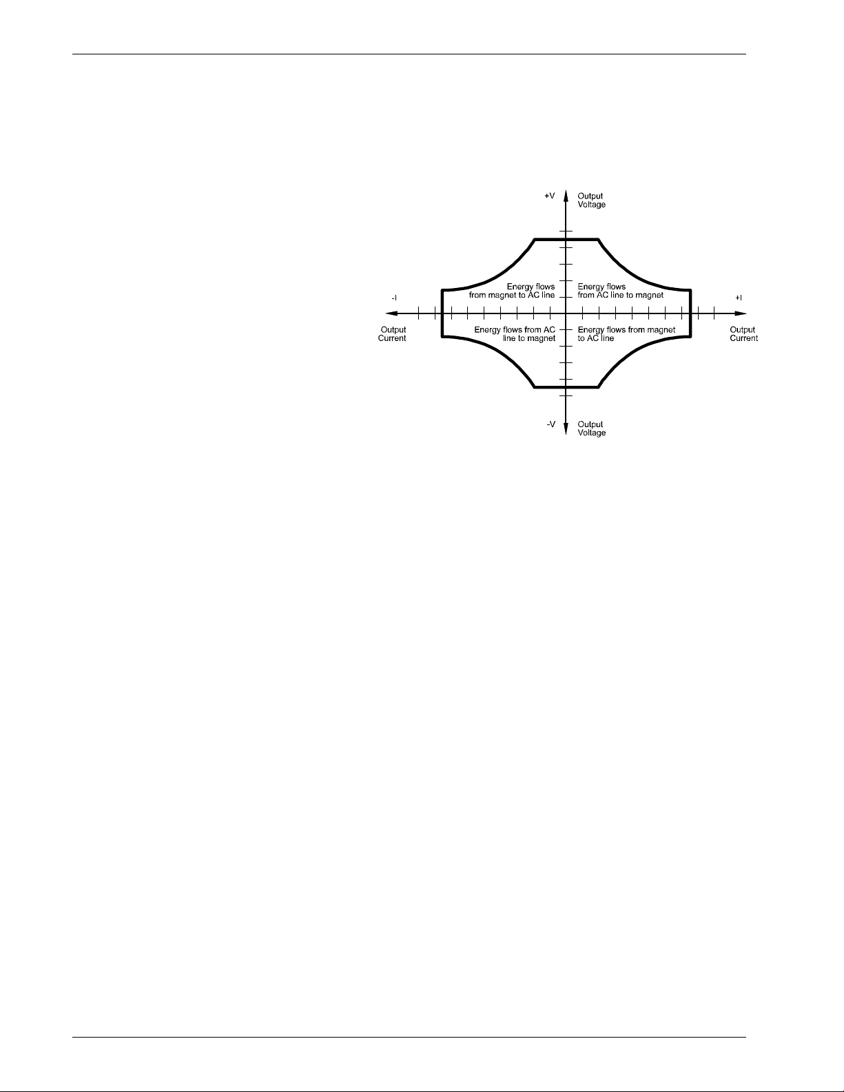
1.3.1 True, Four-Quadrant Bi-directional Power Flow
Model 647 MPS: Sets either positive or
negative current and voltage values. This true,
four-quadrant operation significantly simplifies
test procedures and system design by
eliminating external switching or operator
intervention to reverse current polarity. The
smooth, continuous transition through zero
current allows the user to readily analyze
samples at very small current increments (as
small as 1 mA) about zero. Power flow is bidirectional. Sink power (energy stored in the
magnet) returns to the AC line instead of
dissipating in an energy absorber. The MPS
either transfers power from the AC line to the
magnet, or from the magnet back to the AC
line. The MPS also tolerates AC line faults; in
the event of utility power failure, it draws power
from the charged load to maintain operation
Figure 1-1 Four-Quadrant Power
until utility restoration.
Other conventional MPS's: Consist of a unipolar power supply with an energy absorber to dissipate magnet
energy during discharge. The energy absorber prevents reverse voltage generated during the discharge from
damaging the unipolar supply output. Other conventional supplies dissipate magnet energy in the power
supply output transistor pass-bank. This two-quadrant performance requires the output stage to absorb
considerable power during the discharge. In addition, uniform charge and discharge rates are not always
ensured.
Current reversal requires external current reversal switches or manual lead reversal. These units provide
pseudo-four-quadrant operation which introduces discontinuities at the current reversal point produced by
switching the leads. Current reversal switches may incorporate direction detection diodes which reduce
available magnet charging voltage and dissipate additional power. Current reversal switches must also
interlock to prevent lead reversal when current is present. Current reversal switches complicate high power
cabling requirements, increase chances of introducing output current instabilities, and require time to reverse
leads. Manual lead reversal introduces discontinuity at the current reversal point. A discontinuous transition
through zero current may require a small external supply for near zero current analysis. Utility power failure in
a conventional supply generally results in a magnet quench.
1-4
Introduction

Lake Shore Model 647 Magnet Power Supply User’s Manual
1.3.2 Low Noise, High Stability Current Regulated Output
Model 647 MPS: Maintains a high-stability
low-noise current-regulated output. Digital
Computer
setting and monitoring electronics, and
computer interfacing integrate into power
management and precision analog control
circuitry. This integration maintains high
output stability and repeatability. Extensive
output filtering and noise cancellation
circuitry keep MPS output noise very low.
An alog
Current
Programmer
Analog Programmed
Power Supply
An alog
Vol tage
Programmer
Now
Replaced
by:
The MPS front panel graphic display allows
continuous display of output current and
voltage while setting parameters from the
menu-driven keypad. In addition to the front
panel and remote interface programming,
the MPS includes analog inputs and outputs
for setting and monitoring operating
parameters and requires only 7 inches of
rack space.
Other conventional MPS's: Some use a
Current Reversal
Energy Absorber
DVM
Current
Monitor
DVM
Volt age
Monitor
Computer
Lake Shore MPS
True, Four-Quadrant
Bi-Directional
Power Flow
compliance limited output with current
monitoring to charge the magnet. Others
require output current to drive against the
output current limit to prevent output current
drift. Most use multi-turn potentiometers and
Magnet Load
Figure 1-2 Comparison of Old and New MPS Designs
Magnet Load
digital (or analog) panel meters for front panel current and compliance voltage setting. The elegance and
repeatability of keypad entry is not available. There is no digital setting or monitoring integration in the output
control circuitry. Most achieve computer interfacing by adding computer controlled voltage sources to analog
program the output current and voltage. Additional inputs must be added to digitize the output current and
voltage. Setting and monitoring resolution is one to two orders of magnitude poorer than the standard MPS
provides. External setting and monitoring complicates cabling. Degradation of the output current stability due
to the addition of external cabling is undefined. Output noise specifications are rarely given and sometimes
vary with the type of magnet load driven. These multiple unit configurations require up to 36 inches of rack
space.
1.3.3 Highly Efficient, Air Cooled, Compact Unit
Model 647 MPS: Quiet switched-mode design. The output uses a proprietary pulse width modulated
technique that incorporates power hybrid circuitry. Extremely low conduction loss components minimize
internal power dissipation. The MPS is not a direct off-line switching supply. The output is fully floating and
isolated from ground. Active power factor correction draws a sinusoidal AC current waveform from the utility,
minimizes AC line harmonics, and lowers AC current required. Power factor is the ratio of real power
(measured in watts) to the apparent power (measured in volt-amperes). The combination of quiet switchedmode design and active power factor correction results in a compact, highly efficient, air-cooled unit.
Other conventional MPS's: Most use linear regulated outputs. The output transistor pass-bank internally
dissipates power not delivered to the magnet. Some units use an off-line switching supply to provide the bulk
power and add output regulation. There is no input power factor correction. Low overall efficiency means
higher input power and current. Without power factor correction, a non-sinusoidal current with high peaks
places tremendous stress on fuses, circuit breakers, outlets, and wiring. Dedicated lines may be required
because of potential interaction with other equipment. These factors result in low overall efficiency, large size,
and considerable weight.
Introduction
1-5

Lake Shore Model 647 Magnet Power Supply User’s Manual
This Page Intentionally Left Blank
1-6
Introduction

Lake Shore Model 647 Magnet Power Supply User’s Manual
CHAPTER 2
INITIAL SETUP AND CONNECTIONS
2.1 INSPECTING AND UNPACKING
The MPS ships in a special cardboard box with integrated forklift skid openings. Do not stack anything on top
of the MPS box. Upon receipt, set the box on a level surface with the pallet side down. Inspect the shipping
container for external damage. Make all claims for damage (apparent or concealed) or partial loss of
shipment in writing to Lake Shore within five (5) days from receipt of goods. If damage or loss is apparent,
notify the shipping agent immediately.
Cut off the plastic strapping and lift off the lid. Locate the MPS packing list and use it to check for receipt of all
components, cables, accessories, and manuals. Inspect each item for damage. Use two people to lift the
MPS. Retain internal packing material and box for reshipment. Fill out and send the warranty card.
If there is freight damage to any instruments, promptly file proper claims with the carrier and insurance
company and notify Lake Shore Cryotronics. Notify Lake Shore of any missing parts immediately. Lake Shore
cannot be responsible for any missing parts unless notified within 60 days of shipment. See the standard
Lake Shore Cryotronics, Inc. Warranty on the A Page (immediately behind the title page).
2.2 MPS MOUNTING
After unpacking the MPS and verifying receipt of all packing list items, mount the instrument in a suitable
location. The MPS ships with feet installed and is ready for use as a bench top instrument. The MPS also
ships with 19-inch rack mounting hardware installed for mounting in a standard 19-inch rack enclosure.
CAUTION: To install the MPS in a 19-inch rack mount enclosure at any position other than the bottom,
install a slide rail or runner to support the MPS.
2.3 ENVIRONMENTAL REQUIREMENTS
Operate the MPS in an area with an ambient temperature range of 20 to 30 °C (68 to 86 °F). The unit may be
operated within the range of 15 to 35 °C (59 to 95 °F) with reduced accuracy.
The MPS is intended for laboratory use: no specific humidity or altitude specifications have been determined.
However, relative humidity of 20 to 80 percent (no condensation) and altitudes from sea level to 2.4 km
(8,000 feet) are generally acceptable.
WARNING: To prevent electrical fire or shock hazards, do not expose this instrument to moisture.
Provide adequate ventilation. The fan-cooled MPS draws air in from the sides and exhausts it from the rear;
install it with sufficient space at the rear and sides for air flow. Filter dust and other particulate matter at the
site to a reasonable level. For salt air, corrosive gases, or other air pollutants, consult an air-conditioning
expert for special filtering arrangements.
Setup & Connections
2-1
Lake Shore Model 647 Magnet Power Supply User’s Manual
2.4 CONNECTING THE MPS TO POWER
Read and thoroughly understand sections 2.4.1 through 2.4.3 and the safety recommendations in
the Forward before connecting the MPS to power. Failure to do so may expose operating personnel
to lethal voltages or damage the magnet and/or MPS.
2.4.1 Power and Ground Requirements
The AC power source for the MPS should be frequency and voltage regulated and isolated from sources that
may generate Electromagnetic Interference (EMI). The MPS is designed for single-phase 3-wire alternating
current (AC) power; do not use two-wire (without ground) AC power. Lake Shore recommends Ground Fault
Interrupter (GFI) and Transient Surge Protection circuitry at the AC source.
In areas where AC voltage varies, consider using a constant voltage transformer. For power outages,
consider using an Uninterruptible Power Supply (UPS).
CAUTION: Do not attempt to apply electrical power until the MPS is checked for proper line voltage
settings.
Factory-preset MPS line voltage requirements allow proper operation at the shipping destination. The line
voltage setting is indicated on the rear panel. Before applying power to the main input power cable, check for
correct input power settings for the power source voltage.
Ground the instrument panels and cabinets. The safety ground provides a true ground path for electrical
circuitry and, in the event of internal electrical faults such as shorts, carries the entire fault current to ground
to protect users from electrical shock. The MPS has a three-conductor power input connector which grounds
the MPS chassis when plugged into a 3-wire receptacle.
EMI is both a natural and man-made electromagnetic phenomena which, either directly or indirectly, may
degrade electronic system performance. Natural EMI includes thunderstorms, solar disturbances, cosmic
rays, etc. Man-made EMI includes fixed and mobile transmitters, high voltage power lines, power tools and
appliances, florescent lights, and other equipment containing motors, heaters, etc. Protect the AC source
from EMI. Consider transient surge protectors for lightning protection.
2.4.2 MPS Input Power Ratings
Operate the MPS from a nominal 200, 208, 220, or
240 VAC (–10%, +5%) single-phase AC power
source, 50 to 60 Hz. Table 2-1 lists the input voltage
range and maximum current required for each nominal
input. A rear panel label indicates MPS factory-preset
nominal line voltage. Normally, the line voltage setting
is not changed in the field. Consult the factory to
reconfigure the input power.
Nominal Line
Voltage (VAC)
Line Voltage
Range (VAC)
200 180 to 210 16
208 188 to 218 15
220 198 to 231 14
240 216 to 250 13
Table 2-1 MPS Line Voltage Limits
Maximum Input
Current (A rms)
2.4.3 Input Power Connections
The MPS uses a three-prong detachable input power connector (supplied) to mate with the UL/CSA/IEC
approved rear panel AC input connector. The user supplies a three-conductor power cord rated for at least 85
°C operation. Each conductor must be AWG #16 or larger. Larger wires may be required to prevent excessive
voltage drop in AC power lines if unit is located an extended distance from the main AC distribution terminals.
WARNING: For proper circuit breaker protection, mate the wire connected to the “L” terminal of the
connector to the “L” (hot) side of the line and mate the wire connected to the “N” terminal to the “N”
(neutral) side of the line. Mate the wire connected to the “GND” terminal to earth ground. Do not
operate this instrument without an adequate ground connection.
CAUTION: Before applying power to the MPS, verify that the AC source matches the line voltage
listed on the rear panel.
NOTE: Make connections to the AC power line in accordance with applicable electrical codes. The
international color code for identifying utility supply conductors is green/yellow for earth (“GND”), blue for
neutral (N), and brown for line (L). The US and Canadian codes are green for earth (“GND”), white for neutral
(N), and black for line (L).
2-2
Setup & Connections

Lake Shore Model 647 Magnet Power Supply User’s Manual
Use this procedure to connect input power to the MPS:
1. Loosen the two connector cover screws and open the cover.
2. Slip the strain relief over the power cable with the flanged end at the end to be terminated.
3. Attach the wires to the connector in accordance with prevailing color codes: green or green/yellow to the
“GND” terminal, white or blue to the “N” terminal, and black or brown to the “L” terminal.
4. Position the strain relief, close the cover, and then tighten the cover screws.
5. Connect the other end of the power cord to an appropriate AC power source.
6. Plug the power cord into the detachable power connector plug on the MPS rear panel.
2.5 POWER UP
Read and follow instructions in Paragraphs 2.1 - 2.4.3 and safety recommendations in the Forward before
applying power to the MPS. Do not connect the MPS to the magnet at this point. Short the output terminals
together with a #4 gauge or larger cable. This protects the magnet against incorrect configurations.
Turn on the MPS. It requires approximately 2 seconds for initialization. Initially, all front panel annunciators
come on and the alarm sounds for a short time. Within 1 second, the Fault and Persistent Switch Heater On
annunciators and the alarm turn off. If the MPS detects a high or low AC line fault, it blinks the front panel
Fault annunciator and turns off the input circuit breaker. If this occurs, verify that the AC source matches the
line voltage listed on the MPS rear panel. The MPS front panel AC On LED lights any time the MPS is
connected to the AC line and the MPS power switch is ON.
Initially, the entire display clears and the alarm sounds for a short time. The MPS initializes itself and displays
the model identification. The Normal Display screen appears with a blinking asterisk indicating each update
when the unit is in normal operation.
2.5.1 Magnet Cable Connections
WARNING: Turn off the AC power before changing any rear panel connections and verify that all
connections are securely tightened before reapplying power.
CAUTION: Initially, setup the MPS without connecting it to the magnet. This lessens the chance for
inadvertent damage to the load while the user learns MPS operation.
Make MPS load connections at the
+OUT and –OUT terminals on the rear
panel. These plated copper bus bars
accommodate 1/4 inch mounting
hardware. Use load wires heavy
enough to limit the voltage drop to less
than 0.5 volts per lead. This ensures
proper regulation and prevents
overheating while carrying the output
current. Use remote sensing to
compensate for any voltage drop in the
Area Capacity Resistivity Total Lead Length (feet)
AWG (mm2) Amperes
0
2
4
6
8
53.5
33.6
21.2
13.3
8.4
245
180
135
100
75
Ω/1000 feet
0.09827
0.1563
0.2485
0.3951
0.6282
75 A 100 A 125 A
135
85
53
33
21
101
64
40
25
—
Table 2-2 Load Wire Lengths and Current Capacity
81
51
32
—
—
load leads and obtain a more accurate voltage reading. Stranded AWG #4 wire is capable of carrying in
excess of 125 amperes. Keep conductor temperature under 85 °C for a 35 °C ambient. Table 2-2 lists the
ampere capacity and total +OUT and –OUT lead lengths for load connections.
If connecting multiple loads to the unit, use separate pairs of wires to connect each load to the output
terminals. Cut each pair of connecting wires as short as possible.
Setup & Connections
2-3
Lake Shore Model 647 Magnet Power Supply User’s Manual
2.5.2 Shielding, Grounding, and Noise
For noise reduction, tightly twist and shield the leads from the MPS to the magnet. Connect the shield to the
MPS chassis as shown in figure 2-4.
WARNING: DO NOT place magnet leads in contact with other MPS/system connections or metal parts.
In some instances, the user's measurement leads may pick up noise from the magnet leads. Although this
common mode noise may affect the user's measurement it rarely affects the current in the magnet. If the
user's measurement is earth grounded, some improvement is almost always possible by tying the –OUT
terminal of the MPS to earth ground – either at the MPS chassis or, if the user's system has one, the common
system earth ground point.
WARNING: If the – OUT terminal is tied to earth ground, make certain the +OUT cable from the MPS
contacts no other earth ground point - it forces the MPS output current into this other ground point. If
the other ground point is a small wire, it may melt or catch fire.
2.5.3 MPS Remote Inhibit and Fault Indicator Connections
The MPS has a Fault Indicator
(FLT) output and a discrete
Remote Inhibit (RI) input which
are both interface independent
and provide fault indication and
remote output shutdown in the
event of catastrophic failure. The
Fault Indicator relay contact is
open when the MPS detects no
faults. When the MPS detects an
internal fault, a remote inhibit, or
an output inhibit, it lights the front
panel Fault LED and closes the
relay contact. The contact closure
alerts other system components
of the fault. In an auto-parallel
system (up to four MPS units
connected in parallel) these
TERMINAL LABEL DEFINITION
1
2
3
4
5
6
RI+
RI–
FLT+
FLT–
ON+
ON–
7 NONE
8
OVP
Table 2-3 RI, FLT, ON, and OVP Connections
Remote Inhibit – Active low, TTL-compatible input to
remotely force the output settings to 0 A and 1 V. Also
activate RI by shorting +RI to -RI with a relay contact closure
or a switch.
Fault Indicator – A relay contact that closes to indicate a
fault. Contact rating: 0.25 A resistive at 100 VDC, 3 W, 25
VA.
ON Indicator – A relay contact that closes to indicate when
the front panel circuit breaker is in the ON position. Contact
rating: 0.25 A resistive at 100 VDC, 3 W, 25 VA.
Factory Use Only. Do not connect to this terminal.
In auto-parallel MPS configurations, OVP ensures that the
activation of one MPS Over Voltage Protection circuit
activates all the other parallel MPS units' protection circuits.
signals connect in parallel
between each of the MPS units
(See Paragraph 2.6 for details on
connections between two autoparallel units). Make connections
to a rear panel detachable
terminal block defined in Table 23 and Figure 2-2.
Figure 2-2 RI, FLT, ON and OVP Connections
2.5.4 AC On Indicator
The MPS provides a discrete ON indicator. Terminals 5 and 6 on the terminal block connector, shown in
Figure 2-2 above, connect to relay contacts that close when the front panel circuit breaker is in the ON
position. There is also a front panel LED that lights when the MPS is ON and connected to AC power.
2.5.5 OVP Connection
In auto-parallel MPS configurations, this connection synchronizes the firing of the Over Voltage Protection
(OVP) circuits of each MPS (see Chapter 5). See Paragraph 2.6 and Figure 2-5 for auto-parallel connections.
2-4
Setup & Connections
Lake Shore Model 647 Magnet Power Supply User’s Manual
2.5.6 MPS Analog Current And Voltage Monitoring Connections
The MPS provides amplified and buffered current and voltage monitor output signals at the terminal block on
the back panel. Connect these signals to external meters to indicate output current and voltage. Obtain the
Current Monitor signal through connections to terminals 9 (Im) and 11 (m) with positive output currents
producing a positive monitor voltage of 10 mV/A from Im to m.
Obtain the Voltage Monitor signal through connections to terminals 10 (Vm) and 11 (m) with positive terminal
voltages producing a positive monitor voltage of 10 mV/V from Vm to m.
Table 2-4 Analog Monitoring, Programming, & Remote Sense Connections
TERMINAL LABEL DEFINITION
9 Im
10 Vm
11 m
12 Vp
13 +Vs
14 –Is
15 Ip
16 +Is
17
18
–S
+S
Output Current Monitor – Voltage output from Im to
GND(M) is ±10 mV/A.
Output voltage monitor – Voltage output from Vm to
GND(M) is ±10 mV/V.
Monitor and program ground. GND(m).
Not Used.
Not Used.
Negative voltage supply for programming external
current with a potentiometer
Current programming input voltage. Voltage input from
Ip to GND(m) produces ±100 A/V. Voltage may come
from a voltage source or from the center tap of a
potentiometer connected from -Is to +Is.
Positive voltage supply for programming external
current with a potentiometer.
Remote voltage sense correction.
Correction for load lead drops of up to 0.5 V per lead.
Figure 2-3 Analog Monitoring , Programming, & Remote Sense Connections
2.5.7 External Current Programming
Remotely program MPS output current by an external voltage or potentiometer. Enable external analog
programming via the rear panel I MODE switch. When the I MODE switch is in the INT I position, external
current mode is disabled. When the I MODE switch is in the EXT I position, the external programming voltage
is summed with the internal programming voltage. Set the internal programming to zero for external
programming only. Apply an external voltage from lp to m of 0 to 1.25 volts or use a 10 KΩ potentiometer to
control the output current over the entire range. Make connections to rear panel detachable terminal block
defined in Tables 2-3 and 2-4 and Figures 2-2 and 2-3. The MPS produces 100 A of output current for 1 V at
the current programming input.
NOTE: MPS protection circuits reduce the effect of open external programming leads. An open external
programming lead forces external programming voltage to approximately 0 volts.
Setup & Connections
2-5
Lake Shore Model 647 Magnet Power Supply User’s Manual
2.5.8 Remote Sense Connections
The factory configures the MPS to sense, but not control remote voltage. Call Lake Shore to reconfigure the
MPS to control voltage at the load. When using remote sense, the MPS measures voltage at the magnet
instead of at the MPS output terminals allowing a more accurate reading of magnet voltage by eliminating
voltage drops in the leads connecting the MPS to the magnet. If using remote sense, the MPS bases the
voltage at the voltage monitor output on the remote sense voltage instead of the MPS terminal voltage.
Use AWG #24, shielded, twisted pair wiring for sense leads to minimize pickup of external noise. Any noise
on the sense leads may appear at the unit output. Ground sense shield to the MPS back panel.
Make Remote Sense Connections to rear panel detachable terminal block defined in Table 2-4 and Figure 2-
3.
NOTE: The MPS includes a protection circuit which reduces the effect of open sense leads during remote
voltage sensing operation. If the +S lead opens, the output voltage changes because it is sensed between
+OUT and the negative side of the load. If the –S lead opens, the output voltage changes because it is
sensed between the positive side of the load and –OUT. If both leads open, the output voltage is sensed
internally.
The procedure below configures the MPS for remote voltage sensing as shown in Figure 2-4.
1. Turn off the unit.
MPS Rear View
2. If present, disconnect any wires between the +OUT and –OUT terminals
and the +S and –S connections on the MPS rear panel.
3. Connect the sense leads from the MPS +S and –S connections to the
load. Maintain polarity when making these connections.
CAUTION: Maintain polarity between +S and +OUT and –S and –OUT.
The +S and –S inputs control the output voltage. Improper polarity may
apply damaging voltages to the load.
4. Connect the ground shield to the mounting screw. Make sure that the
shield does not come into electrical contact with either magnet lead.
Maintain
polarity!
Connect -S
to -OUT and
+S to +OUT.
Figure 2-4 Remote Sensing
Connections
2.6 MULTIPLE AUTO-PARALLEL SETUP
Connect up to four MPS units in an auto-parallel configuration for increased output current capability. The
maximum total current allowed is the sum of the maximum currents of the individual units. For example four
623 MPS units provide 4*155 = 620 amps total current. The maximum total power is the sum of the maximum
power ratings of the individual units.
Assign each unit a unique address: 1 for MPS 1, 2 for MPS 2, etc. The MPS at address 1 polls the control bus
to determine if an auto-parallel configuration is present and how many MPS units are involved. When multiple
MPS units are present, MPS 1 sends the output current and voltage limits, ramp status, output current step
limit, and other operating parameters to the other MPS units so all units operate identically.
For two MPS configuration, each MPS is programmed for half of the total output current. This is true for the
ramp destination current and ramp rate. Each MPS contributes half the output current required. MPS 1
software polls MPS 2 to determine the total output current. The output voltage, current settings during a ramp,
and instrument status from MPS 1 are reported (since the values are the same for both units.)
An analog signal is also provided for remote activation of the output over voltage protection (OVP) circuit. The
signals connect in parallel so that the output OVP circuits of each MPS activate in unison.
CAUTION: Consult Lake Shore prior to operating multiple MPS units in auto-parallel mode.
2-6
Setup & Connections
 Loading...