

Lakeshore 642 User Manual

pply
User’s Manual
Model 642
Electromagnet
Power Su
Lake Shore Cryotronics, Inc.
575 McCorkle Blvd.
Westerville, Ohio 43082-8888 USA
E-mail Addresses:
sales@lakeshore.com
service@lakeshore.com
Visit Our Website At:
www.lakeshore.com
Fax: (614) 891-1392
Telephone: (614) 891-2243
Methods and apparatus disclosed and described herein have been developed solely on company funds of Lake Shore Cryotronics, Inc. No government
or other contractual support or relationship whatsoever has existed which in any way affects or mitigates proprietary rights of Lake Shore Cryotronics,
Inc. in these developments. Methods and apparatus disclosed herein may be subject to U.S. Patents existing or applied for. Lake Shore Cryotronics,
Inc. reserves the right to add, improve, modify, or withdraw functions, design modifications, or products at any time without notice. Lake Shore shall
not be liable for errors contained herein or for incidental or consequential damages in connection with furnishing, performance, or use of this material.
Revision 1.3 P/N 119-042 9 January 2008

Lake Shore Model 642 Electromagnet Power Supply User’s Manual
1. Lake Shore warrants that this Lake Shore product (the “Product”) will
be free from defects in materials and workmanship for the Warranty
Period specified above (the “Warranty Period”). If Lake Shore receives
notice of any such defects during the Warranty Period and the Product
is shipped freight prepaid, Lake Shore will, at its option, either repair
or replace the Product if it is so defective without charge to the owner
for parts, service labor or associated customary return shipping cost.
Any such replacement for the Product may be either new or equivalent
in performance to new. Replacement or repaired parts will be
warranted for only the unexpired portion of the original warranty or 90
days (whichever is greater).
2. Lake Shore warrants the Product only if it has been sold by an
authorized Lake Shore employee, sales representative, dealer or
original equipment manufacturer (OEM).
3. The Product may contain remanufactured parts equivalent to new in
performance or may have been subject to incidental use.
4. The Warranty Period begins on the date of delivery of the Product or
later on the date of installation of the Product if the Product is installed
by Lake Shore, provided that if you schedule or delay the Lake Shore
installation for more than 30 days after delivery the Warranty Period
begins on the 31st day after delivery.
5. This limited warranty does not apply to defects in the Product resulting
from (a) improper or inadequate maintenance, repair or calibration, (b)
fuses, software and non-rechargeable batteries, (c) software,
interfacing, parts or other supplies not furnished by Lake Shore, (d)
unauthorized modification or misuse, (e) operation outside of the
published specifications or (f) improper site preparation or
maintenance.
6. TO THE EXTENT ALLOWED BY APPLICABLE LAW, THE
ABOVE WARRANTIES ARE EXCLUSIVE AND NO OTHER
WARRANTY OR CONDITION, WHETHER WRITTEN OR ORAL,
IS EXPRESSED OR IMPLIED. LAKE SHORE SPECIFICALLY
DISCLAIMS ANY IMPLIED WARRANTIES OR CONDITIONS OF
MERCHANTABILITY, SATISFACTORY QUALITY AND/OR
FITNESS FOR A PARTICULAR PURPOSE WITH RESPECT TO
THE PRODUCT. Some countries, states or provinces do not allow
limitations on an implied warranty, so the above limitation or
exclusion might not apply to you. This warranty gives you specific
legal rights and you might also have other rights that vary from
country to country, state to state or province to province.
7. TO THE EXTENT ALLOWED BY APPLICABLE LAW, THE
REMEDIES IN THIS WARRANTY STATEMENT ARE YOUR
SOLE AND EXCLUSIVE REMEDIES.
8. EXCEPT TO THE EXTENT PROHIBITED BY APPLICABLE
LAW, IN NO EVENT WILL LAKE SHORE OR ANY OF ITS
SUBSIDIARIES, AFFILIATES OR SUPPLIERS BE LIABLE FOR
DIRECT, SPECIAL, INCIDENTAL, CONSEQUENTIAL OR
OTHER DAMAGES (INCLUDING LOST PROFIT, LOST DATA
OR DOWNTIME COSTS) ARISING OUT OF THE USE,
INABILITY TO USE OR RESULT OF USE OF THE PRODUCT,
WHETHER BASED IN WARRANTY, CONTRACT, TORT OR
OTHER LEGAL THEORY, AND WHETHER OR NOT LAKE
SHORE HAS BEEN ADVISED OF THE POSSIBILITY OF SUCH
DAMAGES. Your use of the Product is entirely at your own risk.
Some countries, states and provinces do not allow the exclusion of
liability for incidental or consequential damages, so the above
limitation may not apply to you.
LIMITED WARRANTY STATEMENT
WARRANTY PERIOD: ONE (1) YEAR
LIMITED WARRANTY STATEMENT (Continued)
9. EXCEPT TO THE EXTENT ALLOWED BY APPLICABLE LAW,
THE TERMS OF THIS LIMITED WARRANTY STATEMENT DO
NOT EXCLUDE, RESTRICT OR MODIFY, AND ARE IN
ADDITION TO, THE MANDATORY STATUTORY RIGHTS
APPLICABLE TO THE SALE OF THE PRODUCT TO YOU.
CERTIFICATION
Lake Shore certifies that this product has been inspected and tested in
accordance with its published specifications and that this product met its
published specifications at the time of shipment. The accuracy and
calibration of this product at the time of shipment are traceable to the
United States National Institute of Standards and Technology (NIST);
formerly known as the National Bureau of Standards (NBS).
FIRMWARE LIMITATIONS
Lake Shore has worked to ensure that the Model 642 firmware is as free
of errors as possible, and that the results you obtain from the instrument
are accurate and reliable. However, as with any computer-based software,
the possibility of errors exists.
In any important research, as when using any laboratory equipment,
results should be carefully examined and rechecked before final
conclusions are drawn. Neither Lake Shore nor anyone else involved in
the creation or production of this firmware can pay for loss of time,
inconvenience, loss of use of the product, or property damage caused by
this product or its failure to work, or any other incidental or consequential
damages. Use of our product implies that you understand the Lake Shore
license agreement and statement of limited warranty.
FIRMWARE LICENSE AGREEMENT
The firmware in this instrument is protected by United States copyright
law and international treaty provisions. To maintain the warranty, the
code contained in the firmware must not be modified. Any changes made
to the code is at the user’s risk. Lake Shore will assume no responsibility
for damage or errors incurred as result of any changes made to the
firmware.
Under the terms of this agreement you may only use the Model 642
firmware as physically installed in the instrument. Archival copies are
strictly forbidden. You may not decompile, disassemble, or reverse
engineer the firmware. If you suspect there are problems with the
firmware, return the instrument to Lake Shore for repair under the terms
of the Limited Warranty specified above. Any unauthorized duplication
or use of the Model 642 firmware in whole or in part, in print, or in any
other storage and retrieval system is forbidden.
TRADEMARK ACKNOWLEDGMENT
Many manufacturers and sellers claim designations used to distinguish
their products as trademarks. Where those designations appear in this
manual and Lake Shore was aware of a trademark claim, they appear with
initial capital letters and the ™ or
®
symbol.
CalCurve™, Cernox™, Duo-Twist™, Quad-Lead™, Quad-Twist™,
Rox™, and SoftCal™ are trademarks of Lake Shore Cryotronics, Inc.
®
MS-DOS
and Windows® are trademarks of Microsoft Corp.
NI-488.2™ is a trademark of National Instruments.
PC, XT, AT, and PS-2 are trademarks of IBM.
Copyright © 2006 by Lake Shore Cryotronics, Inc. All rights reserved. No portion of this manual may be reproduced,
stored in a retrieval system, or transmitted, in any form or by any means, electronic, mechanical, photocopying,
recording, or otherwise, without the express written permission of Lake Shore.
ii

Lake Shore Model 642 Electromagnet Power Supply User’s Manual
iii

Lake Shore Model 642 Electromagnet Power Supply User’s Manual
This Page Intentionally Left Blank
iv

Lake Shore Model 642 Electromagnet Power Supply User’s Manual
TABLE OF CONTENTS
Chapter/Section Title Page
1 INTRODUCTION ....................................................................................................................................................1-1
1.0 GENERAL.............................................................................................................................................1-1
1.1 DESCRIPTION......................................................................................................................................1-1
1.2 SPECIFICATIONS................................................................................................................................ 1-3
1.3 SAFETY SUMMARY............................................................................................................................. 1-7
1.4 SAFETY SYMBOLS.............................................................................................................................. 1-9
2 MAGNET SYSTEM DESIGN, INSTALLATION, AND OPERATION...................................................................... 2-1
2.0 GENERAL.............................................................................................................................................2-1
2.1 INTRODUCTION...................................................................................................................................2-1
2.2 MAGNET CONSTRUCTION.................................................................................................................2-2
2.3 CONNECTING THE MAGNET..............................................................................................................2-2
2.3.1 Water Hose Connection ....................................................................................................................2-2
2.3.2 Magnet Coil Wiring............................................................................................................................2-2
2.3.3 Temperature Switches and Flow Switches........................................................................................2-4
2.3.4 Cooling Water and Water Valve ........................................................................................................2-4
2.3.5 Grounding.......................................................................................................................................... 2-4
2.3.6 Final Check-Out.................................................................................................................................2-5
2.4 ELECTROMAGNET OPERATION........................................................................................................ 2-5
2.4.1 Air Gap and Pole Caps......................................................................................................................2-5
2.4.2 Maximum Power and Current............................................................................................................2-5
2.4.3 Operation Under Field Control........................................................................................................... 2-7
2.4.4 Avoiding Cooling Water Condensation.............................................................................................. 2-8
3 INSTALLATION......................................................................................................................................................3-1
3.0 GENERAL.............................................................................................................................................3-1
3.1 INSPECTION AND UNPACKING .........................................................................................................3-1
3.1.1 Moving and Handling ............................................................................................................................3-1
3.2 REAR PANEL DEFINITION..................................................................................................................3-2
3.3 POWER WIRING AND SET-UP............................................................................................................3-3
3.3.1 Line Voltage Selection.......................................................................................................................3-3
3.3.2 Circuit Breaker Setting..................................................................................................
3.3.3 Start-Up Fuses ..................................................................................................................................3-5
3.3.4 Cable Entry........................................................................................................................................ 3-5
3.3.5 Power Input Terminals.......................................................................................................................3-5
3.3.6 Wiring Cover...................................................................................................................................... 3-6
3.3.7 Mains Wiring...................................................................................................................................... 3-7
3.4 MAGNET CONNECTOR....................................................................................................................... 3-7
3.5 AUXILIARY CONNECTOR...................................................................................................................3-7
3.6 POWER SUPPLY CONNECTOR .........................................................................................................3-8
3.7 COOLING WATER................................................................................................................................3-8
3.8 MAGNET CABLE CONNECTIONS.......................................................................................................3-9
3.9 ANALOG INPUT/OUTPUT CONNECTIONS ......................................................................................3-11
3.9.1 External Current Programming........................................................................................................3-11
3.9.2 Output Current and Voltage Monitors.............................................................................................. 3-11
3.10 COMPUTER INTERFACE..................................................................................................................3-11
3.10.1 RS-232C Interface Connection........................................................................................................ 3-11
3.10.2 IEEE-488 Interface Connection....................................................................................................... 3-11
3.11 CHASSIS CONNECTION ...................................................................................................................3-11
3.12 DETACHABLE HANDLES ..................................................................................................................3-12
3.13 RACK MOUNTING..............................................................................................................................3-12
.....................3-4
Table of Contents v

Lake Shore Model 642 Electromagnet Power Supply User’s Manual
TABLE OF CONTENTS (Continued)
Chapter/Section Title Page
4 OPERATION...........................................................................................................................................................4-1
4.0 GENERAL.............................................................................................................................................4-1
4.1 TURNING POWER ON.........................................................................................................................4-1
4.2 DISPLAY DEFINITION..........................................................................................................................4-2
4.3 LED ANNUNCIATORS..........................................................................................................................4-2
4.3.1 Fault LED...........................................................................................................................................4-2
4.3.2 Compliance LED................................................................................................................................4-2
4.3.3 Power Limit LED................................................................................................................................4-2
4.3.4 Ramping LED....................................................................................................................................4-2
4.3.5 Remote LED......................................................................................................................................4-2
4.4 KEYPAD DEFINITION ..........................................................................................................................4-3
4.4.1 General Keypad Operation................................................................................................................4-4
4.5 DISPLAY SETUP..................................................................................................................................4-4
4.6 SETTING OUTPUT CURRENT ............................................................................................................4-4
4.7 CURRENT RAMP RATE.......................................................................................................................4-5
4.8 RAMP SEGMENTS...............................................................................................................................4-5
4.9 PAUSE RAMP.......................................................................................................................................4-6
4.10 ZERO OUTPUT ....................................................................................................................................4-6
4.11 MAXIMUM SETTING LIMITS................................................................................................................4-7
4.11.1 Maximum Output Current ..................................................................................................................4-7
4.11.2 Maximum Current Ramp Rate...........................................................................................................4-7
4.12 MAGNET WATER.................................................................................................................................4-8
4.13 INTERNAL WATER...............................................................................................................................4-8
4.14 ERROR STATUS DISPLAY..................................................................................................................4-8
4.15 EXTERNAL CURRENT PROGRAMMING............................................................................................4-9
4.16 LOCKING THE KEYPAD ......................................................................................................................4-9
4.17 COMPUTER INTERFACE ..................................................................................................................4-10
4.17.1 Changing Serial Baud Rate.............................................................................................................4-10
4.17.2 Changing IEEE-488 Interface parameters.......................................................................................4-11
4.18 DEFAULT PARAMETER VALUES..................................................................................................
5 COMPUTER INTERFACE OPERATION................................................................................................................ 5-1
5.0 GENERAL.............................................................................................................................................5-1
5.1 IEEE-488 INTERFACE..........................................................................................................................5-1
5.1.1 Changing IEEE-488 Interface Parameters.........................................................................................5-2
5.1.2 Remote/Local Operation....................................................................................................................5-2
5.1.3 IEEE-488 Command Structure ..........................................................................................................5-2
5.1.3.1 Bus Control Commands.................................................................................................................5-3
5.1.3.2 Common Commands.....................................................................................................................5-3
5.1.3.3 Device Specific Commands...........................................................................................................5-3
5.1.3.4 Message Strings ............................................................................................................................5-3
5.1.4 Status System ...................................................................................................................................5-4
5.1.4.1 Overview........................................................................................................................................5-4
5.1.4.1.1 Condition Registers....................................................................................................................5-4
5.1.4.1.2 Event Registers..........................................................................................................................5-4
5.1.4.1.3 Enable Registers........................................................................................................................5-4
5.1.4.1.4 Status Byte Register...................................................................................................................5-4
5.1.4.1.5 Service Request Enable Register............................................................................................... 5-4
5.1.4.1.6 Reading Registers......................................................................................................................5-7
5.1.4.1.7 Programming Registers..............................................................................................................5-7
5.1.4.1.8 Clearing Registers......................................................................................................................5-7
....4-11
vi Table of Contents

Lake Shore Model 642 Electromagnet Power Supply User’s Manual
TABLE OF CONTENTS (Continued)
Chapter/Section Title Page
5.1.4.2 Status Register Sets......................................................................................................................5-8
5.1.4.2.1 Standard Event Status Register .................................................................................................5-8
5.1.4.2.2 Operation Event Register Set.....................................................................................................5-9
5.1.4.3 Error Status Register Sets ...........................................................................................................5-10
5.1.4.3.1 Hardware Error Status Register Set......................................................................................... 5-10
5.1.4.3.2 Operational Error Status Register Set...................................................................................... 5-11
5.1.4.4 Status Byte and Service Request (SRQ).....................................................................................5-12
5.1.4.4.1 Status Byte Register................................................................................................................. 5-12
5.1.4.4.2 Service Request Enable Register............................................................................................. 5-13
5.1.4.4.3 Using Service Request (SRQ) and Serial Poll..........................................................................5-13
5.1.4.4.4 Using Status Byte Query (*STB) ..............................................................................................5-13
5.1.4.4.5 Using Message Available (MAV) Bit)........................................................................................ 5-13
5.1.4.4.6 Using Operation Complete (*OPC) and Operation Complete Query (*OPC?).......................... 5-14
5.1.5 IEEE-488 Interface Example Programs...........................................................................................5-14
5.1.5.1 IEEE-488 Interface Board Installation for Visual Basic Program..................................................5-14
5.1.5.2 Visual Basic IEEE-488 Interface Program Setup.........................................................................5-16
5.1.5.3 Program Operation ......................................................................................................................5-20
5.1.6 Troubleshooting...............................................................................................................................5-20
5.2 SERIAL INTERFACE OVERVIEW...................................................................................................... 5-21
5.2.1 Changing Baud Rate.......................................................................................................................5-21
5.2.2 Physical Connection........................................................................................................................5-21
5.2.3 Hardware Support ...........................................................................................................................5-22
5.2.4 Character Format ............................................................................................................................5-22
5.2.5 Message Strings.............................................................................................................................. 5-22
5.2.6 Message Flow Control..................................................................................................................... 5-23
5.2.7 Serial Interface Example Programs.................................................................................................5-23
5.2.7.1 Visual Basic Serial Interface Program Setup ...............................................................................5-24
5.2.7.2 Program Operation ......................................................................................................................5-27
5.2.8 Troubleshooting...............................................................................................................................5-27
5.3 COMMAND SUMMARY......................................................................................................................5-28
5.3.1 Interface Commands (Alphabetical Listing)..................................................................................... 5-29
6 OPTIONS AND ACCESSORIES............................................................................................................................6-1
6.0 GENERAL.............................................................................................................................................6-1
6.1 ACCESSORIES INCLUDED.................................................................................................................6-1
6.2 ACCESSORIES AVAILABLE................................................................................................................6-1
7 SERVICE................................................................................................................................................................ 7-1
7.0 GENERAL.............................................................................................................................................7-1
7.1 CONTACTING LAKE SHORE CRYOTRONICS................................................................................... 7-1
7.2 RETURNING PRODUCTS TO LAKE SHORE......................................................................................7-1
7.3 LINE VOLTAGE SELECTION...............................................................................................................7-2
7.4 CIRCUIT BREAKER SETTING.............................................................................................................7-3
7.5 POWER LINE FUSE REPLACEMENT.................................................................................................7-4
7.6 ERROR MESSAGES............................................................................................................................7-5
7.7 ELECTROSTATIC DISCHARGE.......................................................................................................... 7-6
7.7.1 Identification of Electrostatic Discharge Sensitive Components........................................................ 7-6
7.7.2 Handling Electrostatic Discharge Sensitive Components.................................................................. 7-7
7.8 ENCLOSURE BOTTOM REMOVAL AND REPLACEMENT................................................................. 7-7
7.8.1 Removal............................................................................................................................................7-7
7.8.2 Installation .........................................................................................................................................7-7
Table of Contents vii

Lake Shore Model 642 Electromagnet Power Supply User’s Manual
TABLE OF CONTENTS (Continued)
Chapter/Section Title Page
7.9 FIRMWARE REPLACEMENT...............................................................................................................7-7
7.10 CONNECTOR AND CABLE DEFINITIONS........................................................................................7-11
7.10.1 Analog I/O Connector...................................................................................................................... 7-11
7.10.2 Magnet Connector...........................................................................................................................7-11
7.10.3 Auxiliary Connector..........................................................................................................................7-12
7.10.4 Power Supply Connector.................................................................................................................7-13
7.10.5 RS-232C Serial Interface Connector ...............................................................................................7-13
7.10.6 Serial Interface Cable Wiring...........................................................................................................7-14
7.10.7 IEEE-488 Parallel Interface Connector............................................................................................7-14
7.11 CALIBRATION ....................................................................................................................................7-16
7.11.1 Calibration Interface.........................................................................................................................7-16
7.11.2 Calibration Equipment .....................................................................................................................7-17
7.11.3 Calibration Procedure......................................................................................................................7-17
7.11.3.1 Calibrate Current Output Zero......................................................................................................7-17
7.11.3.2 Calibrate Current Reading Zero...................................................................................................7-17
7.11.3.3 Calibrate Output Voltage Reading Zero.......................................................................................7-18
7.11.3.4 Calibrate External Program Voltage Reading Zero...................................................................... 7-18
7.11.3.5 Calibrate Output Current Gain (Span)..........................................................................................7-18
7.11.3.6 Calibrate Current Reading Gain...................................................................................................7-20
7.11.3.7 Calibrate Voltage Reading Gain................................................................................................... 7-20
7.11.3.8 Calibrate External Current Programming Voltage Reading Gain .................................................7-21
7.11.4 Calibrate Specific Interface Commands...........................................................................................7-21
APPENDIX A – GLOSSARY OF TERMINOLOGY....................................................................................................... A-1
APPENDIX B – UNITS FOR MAGNETIC PROPERTIES............................................................................................. B-1
viii Table of Contents

Lake Shore Model 642 Electromagnet Power Supply User’s Manual
LIST OF ILLUSTRATIONS
Figure No. Title Page
1-1 Model 642 Front Panel .............................................................................................................................1-2
2-1 A Typical Electromagnet...........................................................................................................................2-1
2-2 Typical Magnet Water Hook-Up................................................................................................................ 2-2
2-3 Typical Magnet Coil Wiring Showing Series and Parallel Connections..................................................... 2-3
2-4 Typical Thermal Switch, Flow Switch and Valve Wiring............................................................................ 2-4
2-5 Typical Curves of Field vs. Current for Various Air Gaps and Pole Cap Sizes......................................... 2-5
3-1 Model 642 Rear Panel..............................................................................................................................3-3
3-2 Voltage Change Detail..............................................................................................................................3-4
3-3 Circuit Breaker..........................................................................................................................................3-4
3-4 Fuses........................................................................................................................................................3-5
3-5 Typical Cable Entry with Bushing............................................................................................................. 3-5
3-6 Typical Power Input Wiring....................................................................................................................... 3-6
3-7 Wiring Cover Installation...........................................................................................................................3-6
3-8 Typical Magnet Connector Wiring............................................................................................................. 3-7
3-9 Typical Auxiliary Connector Wiring........................................................................................................... 3-7
3-10 Typical Power Supply Connector Wiring................................................................................................... 3-8
3-11 Typical Water Hose Connection ............................................................................................................... 3-8
3-12 Water Valve Connection...........................................................................................................................3-9
3-13 Output Cable Connection....................................................................................................................... 3-10
3-14 Output Lug Cover Installation .................................................................................................................3-10
3-15 Analog Input/Output Connector.............................................................................................................. 3-11
3-16 Mounting Hole Pattern............................................................................................................................ 3-12
4-1 Model 642 Power Push Buttons ............................................................................................................... 4-1
4-2 Model 642 Keypad and LED Layout......................................................................................................... 4-3
5-1 Model 642 Status System.........................................................................................................................5-5
5-2 Standard Event Status Register.............................................................................................
5-3 Operation Event Register .........................................................................................................................5-9
5-4 Hardware Error Status Register.............................................................................................................. 5-10
5-5 Operational Error Status Register........................................................................................................... 5-11
5-6 Status Byte Register and Service Request Enable Register ..................................................................5-12
5-7 GPIB0 Setting Configuration................................................................................................................... 5-15
5-8 DEV 12 Device Template Configuration................................................................................................. 5-15
5-9 Typical National Instruments GPIB Configuration from IBCONF.EXE....................................................5-19
7-1 Model 642 Rear Panel..............................................................................................................................7-2
7-2 Voltage Change Detail..............................................................................................................................7-3
7-3 Circuit Breaker..........................................................................................................................................7-4
7-4 Fuse Holder Detail....................................................................................................................................7-5
7-5 Board Locations........................................................................................................................................ 7-9
7-6 Digital Board Parts Locations ................................................................................................................. 7-10
7-7 Analog I/O Connector Details.................................................................................................................7-11
7-8 Magnet Connector Details......................................................................................................................7-11
7-9 Auxiliary Connector Detail ......................................................................................................................7-12
7-10 Power Supply Connector Details............................................................................................................7-13
7-11 RS-232C (DTE) Connector Details......................................................................................................... 7-13
7-12 IEEE-488 Connector Details................................................................................................................... 7-15
...................5-8
Table of Contents ix

Lake Shore Model 642 Electromagnet Power Supply User’s Manual
LIST OF TABLES
Table No. Title Page
3-1 Rear Panel Connector Identification.........................................................................................................3-2
3-2 Voltage and Current Selection..................................................................................................................3-3
3-3 Current Capacity and Total Lead Lengths ................................................................................................3-9
4-1 Model 642 LED Descriptions ....................................................................................................................4-2
4-2 Model 642 Key Descriptions.....................................................................................................................4-3
4-3 Default Parameter Values.......................................................................................................................4-12
5-1 Binary Weighting of an 8-Bit Register.......................................................................................................5-7
5-2 Register Clear Methods............................................................................................................................ 5-7
5-3 Programming Example to Generate an SRQ..........................................................................................5-13
5-4 IEEE-488 Interface Program Control Properties.....................................................................................5-17
5-5 Visual Basic IEEE-488 Interface Program ..............................................................................................5-18
5-6 Serial Interface Specifications.................................................................................................................5-22
5-7 Serial Interface Program Control Properties...........................................................................................5-25
5-8 Visual Basic Serial Interface Program.....................................................................................................5-26
5-9 Command Summary...............................................................................................................................5-29
7-1 Voltage and Current Selection..................................................................................................................7-3
7-2 Instrument Hardware Errors......................................................................................................................7-5
7-3 Operational Errors ....................................................................................................................................7-6
B-1 Conversion from CGS to SI Units.............................................................................................................B-1
B-2 Recommended SI Values for Physical Constants.....................................................................................B-2
x Table of Contents

Lake Shore Model 642 Electromagnet Power Supply User’s Manual
CHAPTER 1
INTRODUCTION
1.0 GENERAL
This chapter provides an introduction to the Model 642 Electromagnet Power Supply. The Model 642 was designed and
manufactured in the United States of America by Lake Shore Cryotronics, Inc. The Model 642 features include the
following.
• True 4-quadrant (bipolar) 70 A, 35 V output
• 0.1 mA output setting resolution
• Linear regulation minimizes noise and ripple to 0.007% of maximum current into a 0.50 Ω load
• 1.0 mA stability per hour, 5 mA per 24 hour
• CE compliance to both the low voltage directive and the electromagnetic compatibility (EMC) directive
1.1 DESCRIPTION
The Model 642 Electromagnet Power Supply is the ideal supply for small- to medium-sized magnets used in
high-sensitivity materials research applications. The Model 642 is a practical alternative to both the larger one-size-fitsall magnet supplies and the endless adaptations of generic power supplies. By optimizing output power, Lake Shore was
able to concentrate on the performance requirements of the most demanding magnet users. The resulting Model 642
provides high precision, low noise, safety, and convenience.
Precision in magnetic measurements is typically defined as smooth continuous operation with high setting resolution and
low drift. Achieving these goals while driving an inductive load requires unique solutions. The Model 642 delivers up to
70 A at a nominal voltage of 35 V, with the supply acting as either a source or a sink in true 4-quadrant operation. Its
current source output architecture with analog control enables both smooth operation and low drift. A careful blending of
analog and digital circuits provides high setting resolution of 0.1 mA and flexible output programming.
Lake Shore chose linear input and output power stages for the nominal 2450 W output of the Model 642. Linear
operation eliminates the radiated radio frequency (RF) noise associated with switching power supplies, allowing the
Model 642 to reduce the overall noise in its output and the noise radiated into surrounding electronics.
Safety should never be an afterthought when driving an inductive load. The Model 642 incorporates a variety of
hardware and firmware protection features to ensure the safety of the magnet and supply. For improved operator safety,
the power supply was also designed for compliance with the safety requirements of the CE mark, including both the low
voltage and the electromagnetic compatibility (EMC) directive.
Instrument users have come to rely on Lake Shore equipment for convenience and ease of use. The Model 642 includes
features such as built-in current and power limits, internal cooling-water and magnet-water control to minimize
condensation, current ramping and the capability to modulate the output current. Computer interfaces are also integrated
for automation of the magnet system. The Model 642 is truly an excellent one-box solution for controlling an
electromagnet.
Output Architecture
True 4-quadrant output capability of the Model 642 is ideal for the charge and discharge cycling of electromagnets for
both positive and negative fields. Tightly integrated analog control of the 4-quadrant output provides smooth current
change with very low overshoot on output change. The Model 642 has the ability to charge and discharge magnets up
to a 50 A per second rate into a nominal 0.5 Ω, 0.5 H load.
True 4-quadrant operation eliminates the need for external switching or operator intervention to reverse the current
polarity, significantly simplifying system operation. The transition through zero current is smooth and continuous,
allowing the user to readily control the magnetic field as polarity changes.
At static fields, output current drift is also kept low by careful attention in the analog control circuits and layout.
The high stability and low noise of the Model 642 provides a quiet and uniform magnetic field.
Introduction 1-1

Lake Shore Model 642 Electromagnet Power Supply User’s Manual
Output Architecture (Continued)
The Model 642 output architecture relies on low noise, linear input and output stages. The linear circuitry of the Model
642 permits operation with less electrical noise than switch-mode electromagnet power supplies. One key benefit of this
architecture is CE compliance to the electromagnetic compatibility (EMC) directive, including the radiated emissions
requirement.
Output Programming
The Model 642 output current is programmed internally via the keypad, externally by the computer interface, externally
by the analog programming input, or by the sum of the external and internal settings. For internal programming, the
Model 642 incorporates a proprietary digital-to-analog converter (DAC) that is monotonic over the entire output range
and provides a resolution of 0.1 mA.
The Model 642 generates extremely smooth and continuous ramps with virtually no overshoot. The digitally generated
constant current ramp rate is variable between 0.1 mA/s and 99.999 A/s. To ensure a smooth ramp rate, the power supply
updates the high-resolution DAC 23.7 times per second. A low-pass filter on the DAC output smoothes the transitions at
step changes during ramping.
Output Readings
The Model 642 provides high-resolution output readings. The output current reading has a resolution of 0.1 mA. The
output voltage reading reports the voltage at the output terminals with a resolution of 0.1 mV. All output readings can be
prominently displayed on the front panel and read over the computer interface.
Protection
The Model 642 continuously monitors the line voltage, load power, internal power, and load resistance as well as a
variety of other internal circuit parameters for signs of trouble. Some fault conditions result in a warning message while
others will provide a warning message and zero the output. When hazardous conditions exist, the Model 642 will shut
itself off.
NOTE: The Model 642 is equipped with a high-line lockout circuit which will prevent the unit from being turned
on if it is connected to a voltage source that is much higher than the voltage for which it is configured.
Figure 1-1. Model 642 Front Panel
1-2 Introduction

Lake Shore Model 642 Electromagnet Power Supply User’s Manual
Description (Continued)
Interfaces
The Model 642 includes IEEE-488 and RS-232C interfaces that provide access to operating data, stored parameters, and
remote control of all front panel operated functions. A keypad lock-out feature is provided to prohibit any changes made
from the front panel. The Model 642 can then be operated solely with the computer via the RS-232C or IEEE-488
interface.
The Model 642 provides two analog outputs to monitor the output current and voltage. Each output is a buffered,
differential, analog voltage representation of the signal being monitored. The current monitor has a sensitivity of
7 V = 70 A, while the voltage monitor has a sensitivity of 3.5 V = 35 V.
Display and Keypad
The Model 642 incorporates a large 8-line by 40-character vacuum fluorescent display. Output current and output
voltage readings are displayed simultaneously. Five LEDs on the front panel provide quick verification of instrument
status, including ramping, power limit, compliance, fault, and computer interface mode. Error conditions are indicated on
the main display along with an audible tone. Extended error descriptions are available in an error message screen by
pressing the Status key.
The keypad is arranged logically to separate the different functions of the instrument. The most common functions of the
power supply are accessed using a single key press. The keypad can be locked to either lock out all changes or to lock
out just the instrument setup parameters allowing the output of the power supply to be changed.
1.2 SPECIFICATIONS
Output
Type Bipolar, 4-quadrant, DC current source
Current generation Fully linear regulation with digital setting and analog control
Current range ±70 A
Compliance voltage (DC) ±35 V nominal
Power 2450 W nominal
Nominal load 0.5 Ω, 0.5 H
Maximum load resistance 0.6 Ω for ±70 A DC operation at +10% to –5% line voltage
Minimum load resistance 0.4 Ω for ±70 A at +5% to –10% line voltage
Load inductance range 0 H to 1 H
Current ripple 5 mA RMS (0.007%) at 70 A into nominal load
Current ripple frequency Dominated by the line frequency and its harmonics
Temperature coefficient ±15 ppm of full scale/°C
Line regulation ±60 ppm of full scale/10% line change
Stability (1 h) 1 mA/h (after warm-up)
>Stability (24 h) 5 mA/24 h (typical, dominated by temperature coefficient and line regulation)
Isolation Differential output is optically isolated from chassis to prevent ground loops
Slew rate 50 A/s into nominal load
650 A/s maximum into a resistive load
Compliance voltage (AC) ±43 V at +10% to –5% line
Settling time <1 s for 10% step to within 1 mA of output into nominal load
Modulation response ≤ 0.17 Hz at ±70 A sine wave into nominal load, <0.02% THD
≤ 10 Hz at ±10 A sine wave into nominal load, <0.10% THD
Attenuation –0.5 dB at 10 Hz
Protection Short circuit, line loss, low line voltage, high line voltage, output over voltage, output
over current, and over temperature
Connector Two lugs with 6.4 mm (0.25 in) holes for M6 or 0.25 in bolts
Introduction 1-3

Lake Shore Model 642 Electromagnet Power Supply User’s Manual
Specifications (Continued)
Output programming
Internal current setting
Resolution 0.1 mA (20 bit)
Settling time 600 ms for 1% step to within 1 mA (of internal setting)
Accuracy ±10 mA ±0.05% of setting
Operation Keypad, computer interface
Protection Programmable current setting limit
Internal current ramp
Ramp rate 0.1 mA/s to 99.999 A/s (compliance limited)
Update rate 23.7 increments/s
Ramp segments 5
Operation Keypad, computer interface
Protection Programmable ramp rate limit
External current programming
Sensitivity 10 V/70 A
Resolution Analog
Accuracy ±10 mA ±1% of setting
Input resistance 20 kΩ
Operation Voltage program through rear panel, can be summed with internal current setting
Limits Internally clamped at ±10.1 V and bandwidth limited at 40 Hz to protect output
Connector Shared 15-pin D-sub
Readings
Output current
Resolution 0.1 mA
Accuracy ±5 mA ±0.05% of rdg
Update rate 2.5 rdg/s display, 10 rdg/s interface
Output voltage (at supply terminals)
Resolution 1mV
Accuracy ±5 mV ±0.05% of rdg
Update rate 2.5 rdg/s display, 5 rdg/s interface
Front panel
Display type 8-line by 40-character graphic vacuum fluorescent display module
Display readings Output current, output voltage, and internal water temperature
Display settings Output current and ramp rate
Display annunciators Status and errors
LED annunciators Fault, Compliance, Power Limit, Ramping, Remote
Audible annunciator Errors and faults
Keypad type 26 full travel keys
Keypad functions Direct access to common operations, menu-driven setup
Power White flush ON and black extended OFF push buttons
1-4 Introduction

Lake Shore Model 642 Electromagnet Power Supply User’s Manual
Specifications (Continued)
Interface
IEEE-488.2 interface
Features SH1, AH1, T5, L4, SR1, RL1, PP0, DC1, DT0, C0, E1
Reading rate To 10 rdg/s
Software support National Instruments LabVIEW
™ driver (consult Lake Shore for availability)
Serial interface
Electrical format RS-232C
Baud rates 9600, 19200, 38400, 57600
Reading rate To 10 rdg/s
Connector 9-pin D-sub (DTE)
Output current monitor
Sensitivity 7 V/70 A
Accuracy ±1% of full scale
Noise 1 mV RMS
Source impedance 20 Ω
Connector Shared 15-pin D-sub
Output voltage monitor
Sensitivity 3.5 V/35 V
Accuracy 1% of full scale
Noise 1 mV RMS
Source impedance 20 Ω
Connector Shared 15-pin D-sub
Power supply cooling water
Remote enable input TTL low or contact closure to enable output; jumper required if unused
Valve power output 24 VAC at 1 A maximum, automatic or manual control
Connector Shared 4-pin detachable terminal block
Flow switch and water valve optional
Magnet cooling water
Remote enable input TTL low or contact closure to enable output; jumper required if unused
Valve power output 24 VAC at 1 A maximum, automatic or manual control
Connector Shared 4-pin detachable terminal block
Flow switch, temperature switch, and water valve not included
Auxiliary
Emergency stop Requires 1 A, 24 VAC normally closed (NC) contact to enable power-up; jumper required if
unused
Fault output Relay with normally open (NO) or normally closed (NC) contact, 30 VDC at 1 A
Remote enable TTL low or contact closure to enable output, jumper required if unused
Connector Shared 8-pin detachable terminal block
Emergency stop and enable switches not included
Introduction 1-5

Lake Shore Model 642 Electromagnet Power Supply User’s Manual
Specifications (Continued)
General
Line power
Power 5500 VA max
Voltage and current 200/208 VAC ±10%, 13 A/phase
220/230 VAC ±10%, 12 A/phase
380 VAC ±10%, 7 A/phase
400/415 VAC ±10%, 6.5 A/phase
Protection Three phase thermal relay, with adjustable current setting
Two class CC 1/4 A fuses
Over-voltage lockout circuit
Frequency 50 Hz or 60 Hz
Configuration 3-phase delta
Connector 4-pin terminal block
Line voltage must be specified at time of order but is field reconfigurable
Cable from power supply to facility power not included
Cooling water
Flow rate 5.7 L (1.5 gal)/min minimum
Pressure range 34 kPa (5 psi) to 552 kPa (80 psi)
Pressure drop 10 kPa (1.5 psi) at 5.7 L (1.5 gal)/minute minimum for power supply only
Temperature 15 °C to 30 °C (non condensing)
Connection Two 10 mm (0.38 in) hose barbs
CAUTION: Internal condensation can cause damage to the power supply
Enclosure type 7 U high, 19 in rack mount with integral rack mount ears (25 mm (1 in) air space required on
each side for ventilation
Size 483 mm W × 310 mm H × 572 mm D (19 in × 12.2 in × 22.5 in) with front handles removed
Weight 74 kg (163 lb)
Shipping size 635 mm W × 559 mm H × 736 mm D (25 in × 22 1n × 29 in)
Shipping weight 79.5 kg (175 lb)
Ambient temperature 15 °C to 35 °C at rated accuracy, 5 °C to 40 °C at reduced accuracy
Humidity Non condensing
Warm-up 30 min at output current setting
Approvals CE mark – low voltage compliance to EN61010-3, EMC compliance to EN55022-1
Calibration schedule 1 year
Ordering Information
Part Number Ordering Information
642-204 Model 642 ±70 A ±35 V, 2.5 kW, 204/208 VAC
642-225 Model 642 ±70 A ±35 V, 2.5 kW, 220/230 VAC
642-380 Model 642 ±70 A ±35 V, 2.5 kW, 380 VAC
642-408 Model 642 ±70 A ±35 V, 2.5 kW, 400/415 VAC
Options
6041 Water flow switch, 2 gallons/min
6042 64X MPS water valve with mounting bracket and hose barb fittings
1-6 Introduction

Lake Shore Model 642 Electromagnet Power Supply User’s Manual
Accessories included
MAN-642 Model 642 user manual
6031 Two front handles
6032 Two rear handles
6051 Terminal block, 4 pin
6052 Terminal block, 8 pin
6252 15-pin D-sub mating connector, analog I/O
108-654 Strain relief bushing kit
----- Calibration certificate
Accessories available
6201 1 m (3.3 ft) long IEEE-488 (GPIB) computer interface cable
6261 3 m (10 ft) magnet cable kit, AWG 4
6262 6 m (20 ft) magnet cable kit, AWG 4
CAL-642-CERT Instrument recalibration with certificate
CAL-642-DATA Instrument recalibration with certificate and data
1.3 SAFETY SUMMARY
Observe these safety precautions during all phases of instrument operation, service, and repair. Failure to comply with
these precautions or with specific warnings elsewhere in this manual violates safety standards of design, manufacture,
and intended instrument use. Lake Shore assumes no liability for Customer failure to comply with these requirements.
The Model 642 protects the operator and surrounding area from electric shock or burn, mechanical hazards, excessive
temperature, and spread of fire from the instrument. Environmental conditions outside of the conditions below may pose
a hazard to the operator and surrounding area.
• Indoor use.
• Altitude to 2000 meters.
• Temperature for safe operation: 5 °C to 40 °C.
• Over voltage category II.
• Maximum relative humidity: 80% for temperature up to
31 °C decreasing linearly to 50% at 40 °C.
• Power supply voltage fluctuations not to exceed ±10%
of the nominal voltage.
• Pollution degree 2.
Power and Ground Connections
This instrument must be connected to a dedicated three-phase power circuit with proper size of circuit breaker. (Refer
to Chapter 3 – Installation) Verify that the unit has been configured for the correct input voltage. The neutral line, if
available, is not used. The unit may be hard-wired or connected with a flexible cable and plug. In all cases the correct
size wire must be chosen for the current drawn and the length of cable used. To minimize shock hazard, the electrical
ground (safety ground) lead must be connected. If a flexible cable and plug are used, plug the power cable into an
approved electrical outlet. The power jack and mating plug of the power cable must meet Underwriters Laboratories
(UL) and International Electromechanical Commission (IEC) safety standards. Power wiring must comply with
electrical codes of the locality in which the unit is installed.
Ventilation
The instrument has ventilation holes in its side panels. Do not block these holes when the instrument is operating.
Provide at least 25 mm (1 in) of air space on each side for ventilation.
Do Not Operate In An Explosive Atmosphere
Do not operate the instrument in the presence of flammable gases or fumes. Operation of any electrical instrument
in such an environment constitutes a definite safety hazard.
Keep Away From Live Circuits
Operating personnel must not remove instrument covers. Refer component replacement and internal adjustments to
qualified maintenance personnel. Do not replace components with power cable connected. To avoid injuries, always
disconnect power and discharge circuits before touching them.
Introduction 1-7

Lake Shore Model 642 Electromagnet Power Supply User’s Manual
Safety Summary (Continued)
Do Not Substitute Parts Or Modify Instrument
Do not install substitute parts or perform any unauthorized modification to the instrument. Return the instrument to an
authorized Lake Shore representative for service to ensure that safety features are maintained.
Prevent Cooling Water Condensation
Do not operate the power supply when cooling water temperature is at or lower than the dew point for local
atmospheric conditions. Condensation on cooling water lines inside the power supply can cause severe damage.
Refer to Section 2.4.4 for additional details.
Cleaning
Do not submerge instrument. Clean only with a damp cloth and mild detergent on exterior surfaces only.
Moving and Handling
Four handles are provided for ease of moving and handling the Model 642. The handles can be used in place of
lifting lugs when cloth straps are used. Always use all four handles when moving the unit. Because of its weight, the
Model 642 should be handled by mechanical means. If for some reason it is necessary to move it by hand, a minimum
of two people is required.
CAUTION: To avoid injury to personnel, always observe proper lifting techniques in accordance with OSHA and
other regulatory agencies.
1-8 Introduction
Safety Summary (Continued)
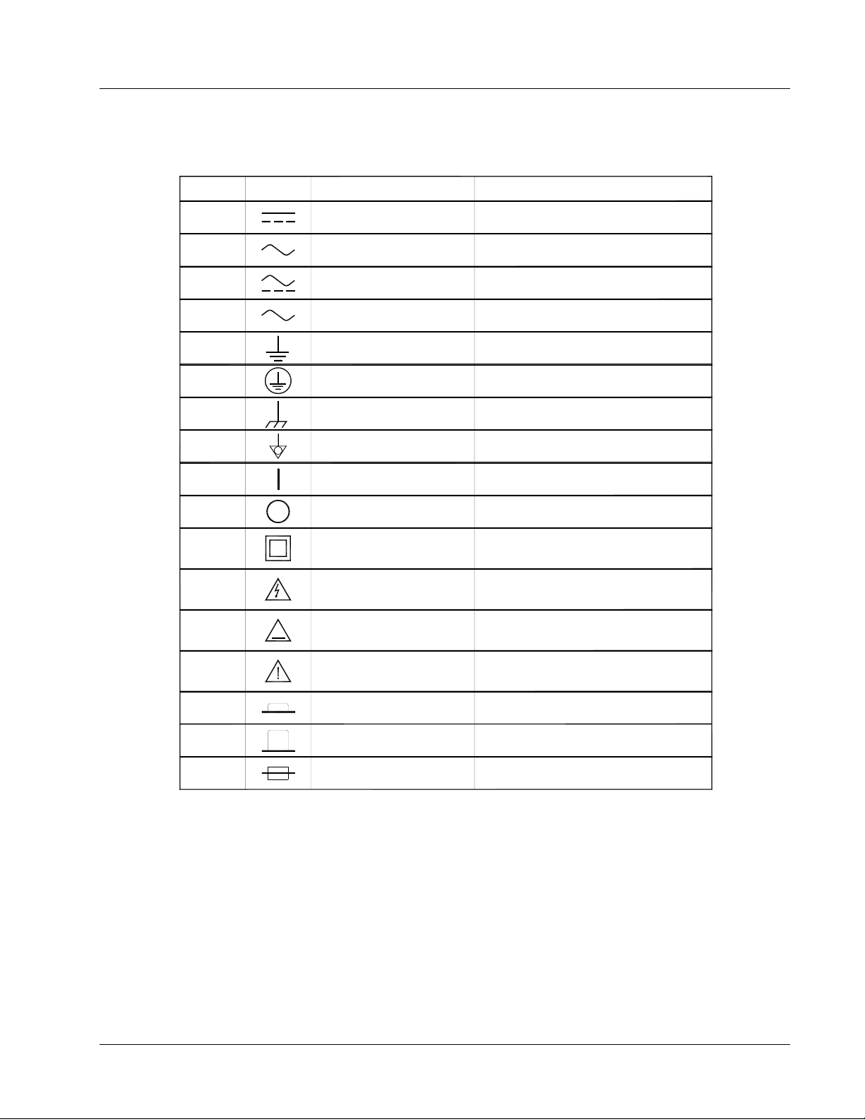
1.4 SAFETY SYMBOLS
Lake Shore Model 642 Electromagnet Power Supply User’s Manual
Number
1
2
3
4
5
6
7
8
9
10
11
12
13
14
Symbol
3
Publication Description
IEC 417, No. 5031 Direct current
IEC 417, NO. 5032
IEC 417, No. 5033 Both direct and alternating current
IEC 617-2, No. 02-02-06 Three-phase alternating current
IEC 417, No. 5017 Earth (ground) TERMINAL
IEC 417, No. 5019 PROTECTIVE CONDUCTOR TERMINAL
IEC 417, No. 5020 Frame or chassis ground
IEC 417, No. 5021 Equipotentiality
IEC 417, No. 5007 On (supply)
IEC 417, No. 5008 Off (supply)
IEC 417, No. 5172 DOUBLE INSULATION OR REINFORCED
ISO 3864, No. B.3.6
Bcakground color-yellow Caution, risk of electric shock
Symbol and outline-black
IEC 417, No. 5041
Background color-yellow Caution, hot surface
~~~
Symbol and outline-black
ISO 3864, No. B.3.1
Background color-yellow Caution (refer to accompanying documents)
Symbol and outline-black
Alternating current
Equipment protected by
INSULATION
15
16
None
IEC 417, No. 5268-a In-position of bistable push control
IEC 417, No. 5269-a Out-position of bistable push control
IEC 1010-1 Fuse
Introduction 1-9

Lake Shore Model 642 Electromagnet Power Supply User’s Manual
This Page Intentionally Left Blank
1-10 Introduction

Lake Shore Model 642 Electromagnet Power Supply User’s Manual
CHAPTER 2
MAGNET SYSTEM DESIGN,
INSTALLATION, AND OPERATION
2.0 GENERAL
This chapter provides the user insight into the design, installation, and operation of a typical electromagnet. For
information on how to install the Model 642 please refer to Chapter 3. For Model 642 operation information, refer to
Chapter 4.
2.1 INTRODUCTION
A magnet used with the Model 642 Power Supply is typically an iron pole, twin coil, 4-inch pole diameter, variable air
gap, water cooled electromagnet. Larger magnets can be used depending on their electrical parameters and the magnetic
field requirements. The electromagnet provides a uniform magnetic field in the air gap between two adjustable poles.
The samples, which are to be tested for their magnetic properties, are placed in the air gap with appropriate monitoring
equipment attached. By varying the polarity and intensity of the field, useful data can be collected. A typical
electromagnet is shown in Figure 2-1.
Figure 2-1. A Typical Electromagnet
Magnet System Design 2-1
Lake Shore Model 642 Electromagnet Power Supply User’s Manual
2.2 MAGNET CONSTRUCTION
The magnet consists of two water-cooled coils surrounding adjustable iron poles, which are fitted into an iron frame.
The frame supports the poles and coils, and improves the magnet’s efficiency. The iron poles are fitted with adjusting
mechanisms so that the air gap width can be set. Lock mechanisms are provided to hold the poles in place after
adjustment is made. The poles faces have pole caps attached, which provide the desired magnetic focus. The size and
shape of the pole caps are chosen according to the size of sample being tested and the magnetic field requirement.
2.3 CONNECTING THE MAGNET
Connecting the magnet to the power supply requires three separate circuits: the cooling water hoses, the main high
current power lines, and the safety switches which may include any combination of temperature and flow switches.
These connections are shown below.
2.3.1 Water Hose Connection
Water-cooling is essential for these magnets. The power dissipated can raise the temperature of the coils to the point
where they will be destroyed. In addition, the samples being tested may exhibit changes in their magnetic performance
with changes in temperature causing errors in the collected data. Typical water connection is shown in Figure 2-2. The
magnets may be supplied with hose barbs or standard hose fittings. The coils are connected in parallel so that the water
temperature rise is the same for both. Every effort should be made to insure that the flow rate in both coils is the same.
The minimum flow required is usually specified by the magnet vendor.
MAGNET COIL
MAGNET WATER CONNECTION
HOSE BARB FITTING
HOSE CLAMP
REENFORCED HOSE
OPTIONAL FLOW SWITCH
TEE
WATER VALVE
WATER FILTER
HOSE BARB FITTING
HOSE CLAMP
REENFORCED HOSE
Figure 2-2. Typical Magnet Water Hook-Up
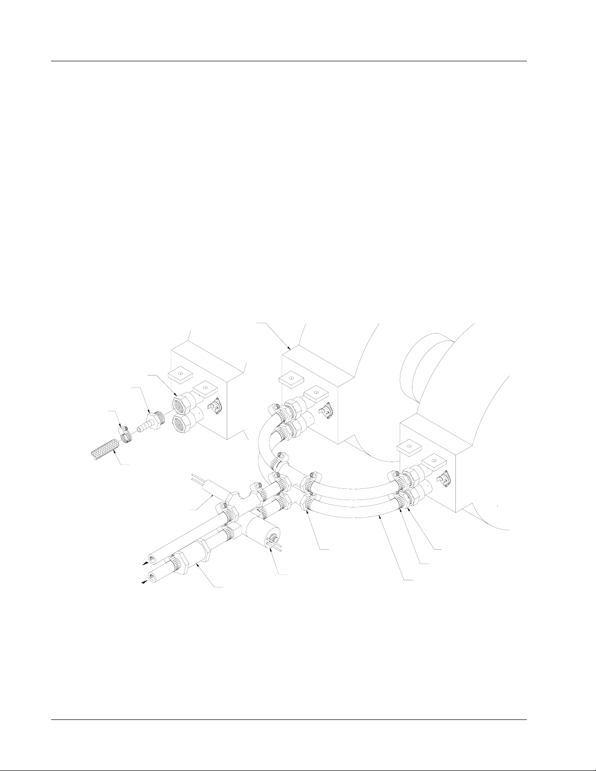
2.3.2 Magnet Coil Wiring
Typical magnet coil wiring is shown in Figure 2-3. The connecting cable used should be of sufficient gage to prevent
excessive voltage drop and heat rise in the cable. The cables should be as short as possible to minimize the voltage drop.
Current carrying capacities for various sizes of cables and cable lengths are shown in Table 3-3. The connections must be
made with the correct size of hardware for the magnet terminal. We recommend the use of a spring or Belleville washer
for cable terminations. When the parts of a connection expand and contract with changes in temperature, they tend to
loosen. A spring washer will reduce this tendency.
2-2 Magnet System Design

BELLEVILLE WASHER
CABLE CONNECTION
Lake Shore Model 642 Electromagnet Power Supply User’s Manual
POWER LEAD
CROSS CONNECTION WIRING
(PARALLEL WIRING)
POWER LEAD
BOLT
MAGNET POWER LUG
PLAIN WASHER
NUT
POWER LEAD
CROSS CONNECTION WIRING
(SERIES WIRING)
POWER LEAD
Figure 2-3. Typical Magnet Coil Wiring Showing Series and Parallel Connections
Magnet System Design 2-3
Lake Shore Model 642 Electromagnet Power Supply User’s Manual
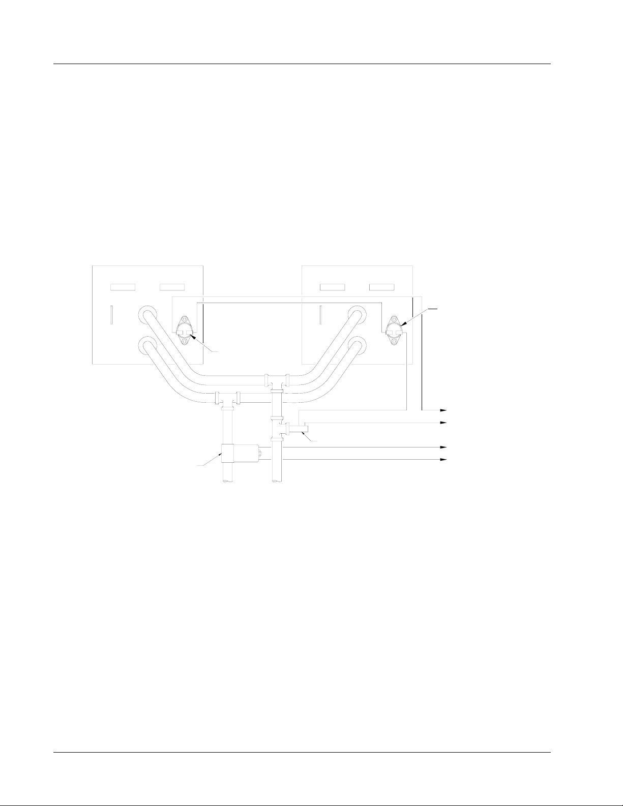
2.3.3 Temperature Switches and Flow Switches
As discussed in Section 2.3.1, water-cooling for the magnet is essential. To protect the magnet from damage resulting
from an interruption in cooling water, a flow switch, temperature switches or both should be installed. The switches must
have a normally closed contact, and if multiple switches are used, they must be connected in series. The switches are
then connected to the Flow Switch terminals of the Magnet Connector on the Model 642. The Model 642 monitors the
switches and if an open is detected, the output current is ramped to zero. (Flow switch monitoring depends on water
valve mode setting. See sections 4.12 and 4.13 for details.)Given the cost of the magnet, it is prudent to use both
temperature and flow switches. Some installations use two flow switches, one in the exhaust line of each coil so that if a
clog occurs in only one coil, it can be detected. Figure 2-4 shows the typical flow and temperature switch connection.
CAUTION: Care must be used in the selection of the flow switch. Some switches use a sensitive reed switch,
which can be overpowered by stray flux from the magnet and will not open when the magnet is
operating at high field. The flow switch must be tested by turning off the water while the magnet is
operating at full current.
THERMAL SWITCH
THERMAL SWITCH
TO 642 MAGNET CONNECTOR FLOW SWITCH CONTACTS
FLOW SWITCH
TO 642 MAGNET CONNECTOR VALVE CONTACTS
WATER VALVE
INLET OUTLET
Figure 2-4. Typical Thermal Switch, Flow Switch and Valve Wiring
2.3.4 Cooling Water and Water Valve
The cooling water for the magnet can be drawn from the municipal water facility or from a dedicated re-circulating water
chiller designed for this purpose. When water is drawn from the municipal water facility, the water should be turned on
only when it is required to reduce consumption and reduce the likelihood of scale build-up in the magnet. The water can
be turned on and off manually when the magnet is used, or automatically with a solenoid valve. The Model 642 provides
automatic control and a 24 VAC at 1 A output for this purpose. The optional water valve is shown in Figure 2-2. The
water inlet line should also be fitted with a sediment filter (not shown) to reduce scale build-up in the magnet coils and
connecting lines.
2.3.5 Grounding
A ground connection (tapped hole) is usually available at the rear of the electromagnet frame. This ground point is
provided for customers who would like to use the electromagnet frame as a signal ground or will be bringing hazardous
live voltages near the electromagnet and would like to make it an electrical safety ground. Please verify suitability for
such a function and compatibility with local and national electrical codes before making ground connections. Scrape off
excess paint near the connecting screw to ensure a good electrical contact with the bare steel of the electromagnet frame.
2-4 Magnet System Design

Lake Shore Model 642 Electromagnet Power Supply User’s Manual
2.3.6 Final Check-Out
When all of the connections have been made the system should be tested to be sure it is operating correctly. The settings
for the magnet water should be checked to verify that they are correct for the configuration which has been installed
(Refer to Section 4.12 – Magnet Water). The maximum current setting for the magnet should be set also (Refer to
Section 2.4.2 and Section 4.11.1.)
2.4 ELECTROMAGNET OPERATION
This section provides a brief description of the typical operation of an electromagnet. For operation of the Model 642,
refer to Chapter 4.
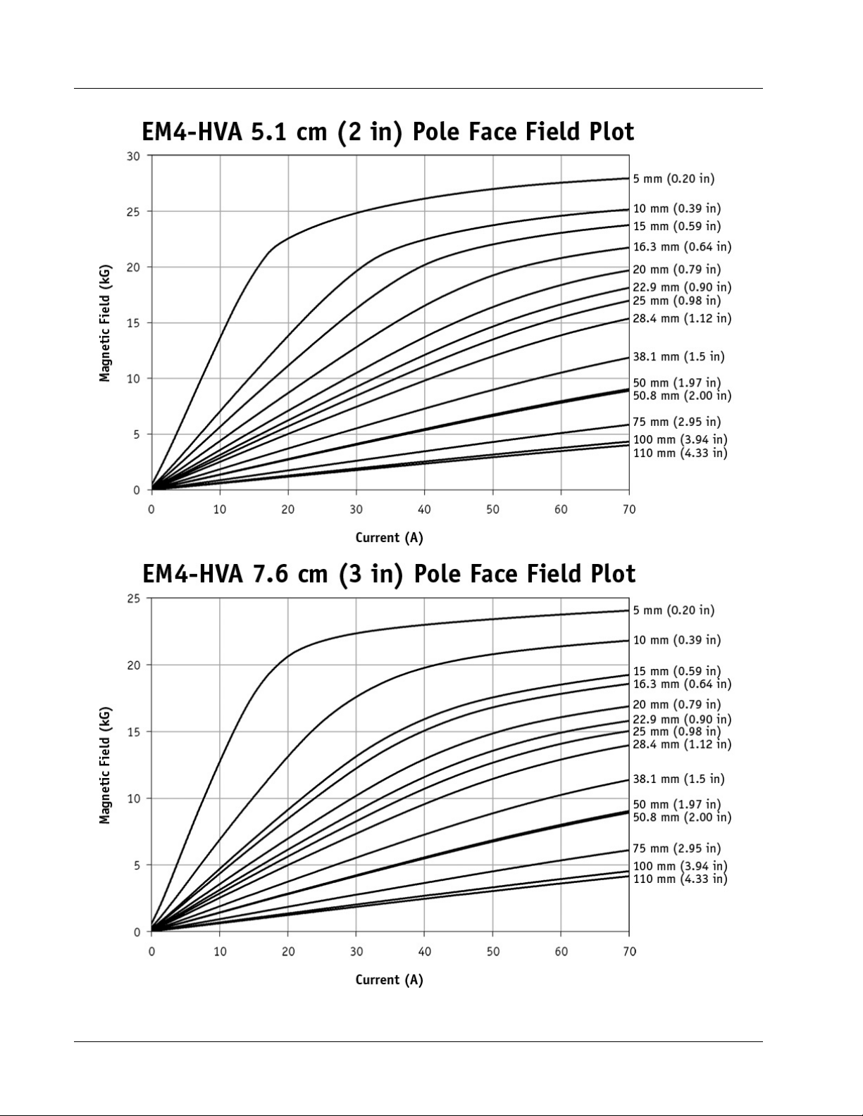
2.4.1 Air Gap and Pole Caps
The first step in setting up a magnet for operation is to select the proper pole caps and adjust the air gap. These
parameters are determined by the size and shape of the sample, and the connections that must be made to the sample.
Generally, a smaller pole face provides a higher field within the air gap. A smaller air gap also provides a higher field.
The pole faces must be selected to accommodate the size of the sample being tested. The air gap is selected based on the
size of the sample and the other equipment being used. The curves for Field versus Current for various air gaps and pole
cap sizes for the Lake Shore Model EM4-HVA are shown in Figure 2-5. It also shows that these parameters are not
linear. This must be taken into account when operating an electromagnet. To obtain linearity, it is necessary to operate
the magnet and power supply under field control. (Refer to Section 2.4.4)
2.4.2 Maximum Current and Power
The Model 642 was designed to operate with a magnet load resistance of 0.50 Ω, but will work with a resistance range of
0.40 Ω to 0.60 Ω. The resistance of a magnet will rise with a rise in temperature and this should be taken into account.
The power dissipated in the magnet is given by: P=I
2
R. If the current remains constant, the power dissipated will rise
proportionately with the rise in resistance. The Model 642 allows the user to set a maximum current limit to prevent
damage to the magnet. (Refer to Section 4.11.1.)
Figure 2-5. Typical Curves of Field vs. Current for Various Air Gaps and Pole Cap Sizes (Sheet 1 of 3)
Magnet System Design 2-5
Lake Shore Model 642 Electromagnet Power Supply User’s Manual
Figure 2-5. Typical Curves of Field vs. Current for Various Air Gaps and Pole Cap Sizes (Sheet 2 of 3)
2-6 Magnet System Design

Lake Shore Model 642 Electromagnet Power Supply User’s Manual
Figure 2-5. Typical Curves of Field vs. Current for Various Air Gaps and Pole Cap Sizes (Sheet 3 of 3)
2.4.3 Operation Under Field Control
To obtain a linear field ramp, a magnetic sensor such as a Hall probe is placed in the air gap along with the sample being
tested. The sensor is connected to a Gaussmeter. The output of the Gaussmeter is used to correct the programming input
to the power supply. In this way non-linearity can be corrected. Lakeshore manufactures probes and Gaussmeters for this
purpose.
Magnet System Design 2-7

Lake Shore Model 642 Electromagnet Power Supply User’s Manual
2.4.4 Avoiding Cooling Water Condensation
If the temperature of the cooling water is too cool relative to the air temperature and humidity, condensation can occur.
Condensation inside the power supply can cause severe damage. To avoid condensation, the power supply operator must
remain cognizant of the ambient air temperature, cooling water temperature, and the relative humidity. Lake Shore
defines the limits of these conditions as follows: ambient temperature = 18
– 28 °C (64 – 82 °F), cooling water
temperature = 15 – 25 °C (59 – 77 °F), and humidity = 20 – 80% (non-condensing). Knowing the actual state of these
conditions, the operator can calculate the dew point, or temperature at which condensation will occur. Tables 2-1 and 2-2
are included to aid in dew point calculation.
Table 2-1. Dew Point Calculation Table (In Degrees Celsius)
% Relative Humidity
°C 100 95 90 85 80 75 70 65 60 55 50 45 40 35 30 25 20 15 10
32 32 31 31 29 28 27 26 24 23 22 20 18 17 15 12 9 6 2 0
29 29 28 27 27 26 24 23 22 21 19 18 16 14 12 10 7 3 0 –
27 27 26 25 24 23 22 21 19 18 17 15 13 12 10 7 4 2 0 –
24 24 23 22 21 20 19 18 17 16 14 13 11 9 7 5 2 0 – –
21 21 20 19 18 17 16 15 14 13 12 10 8 7 4 3 0 – – –
18 18 17 17 16 15 14 13 12 10 9 7 6 4 2 0 – – – –
16 16 14 14 13 12 11 10 9 7 6 5 3 2 0 – – – – –
Table 2-2. Dew Point Calculation Table (In Degrees Fahrenheit)
% Relative Humidity
°F 100 95 90 85 80 75 70 65 60 55 50 45 40 35 30 25 20 15 10
90 90 88 87 85 83 81 79 76 74 71 68 65 52 59 54 49 43 36 32
85 85 83 81 80 78 76 74 72 69 67 64 61 58 54 50 45 38 32 –
80 80 78 77 75 73 71 69 67 65 62 59 56 53 50 45 40 35 32 –
75 75 73 72 70 68 66 64 62 60 58 55 52 49 45 41 36 32 – –
70 70 68 67 65 63 61 59 57 55 53 50 47 44 40 37 32 – – –
65 65 63 62 60 59 57 55 53 50 48 45 42 40 36 32 – – – –
60 60 58 57 55 53 52 50 48 45 43 41 38 35 32 – – – – –
Example: Determine the actual air temperature and relative humidity. Find the closest air temperature in the left-hand
column and the closest relative humidity across the top. If the air temperature is 24 °C (75 °F) and the relative humidity
is 35%, the intersection of the two shows a dew point of 7 °C (45 °F). Therefore, for the given conditions, the cooling
water must remain above 7 °C (45 °F) to prevent condensation.
2-8 Magnet System Design

Lake Shore Model 642 Electromagnet Power Supply User’s Manual
CHAPTER 3
INSTALLATION
3.0 GENERAL
This chapter provides general installation instructions for the Model 642 Electromagnet Power Supply. CAUTION: To
ensure the best possible performance and maintain operator safety, read this entire chapter before installing the
instrument and applying power. Serious hazards can exist when an instrument of this power capacity is used incorrectly.
If you do not understand any section of this manual, consult Lake Shore for clarification. Lake Shore Cryotronics
assumes no responsibility for damage or injuries incurred due to improper installation, defeat of any of the safety
features or misuse of this power supply.
3.1 INSPECTION AND UNPACKING
Inspect shipping containers for external damage before opening them. Photograph any container that has significant
damage before opening it. If there is visible damage to the contents of the container, contact the shipping company and
Lake Shore immediately, preferably within 5 days of receipt of goods. Keep all damaged shipping materials and contents
until instructed to either return or discard them.
Open the shipping container and keep the container and shipping materials until all contents have been accounted for.
Check off each item on the packing list as it is unpacked. Instruments themselves may be shipped as several parts. The
items included with the Model 642 are listed below. Contact Lake Shore immediately if there is a shortage of parts or
accessories. Lake Shore is not responsible for any missing items if not notified within 60 days of shipment.
Inspect all items for both visible and hidden damage that occurred during shipment. If damage is found, contact Lake
Shore immediately for instructions on how to file a proper insurance claim. Lake Shore products are insured against
damage during shipment but a timely claim must be filed before Lake Shore will take further action. Procedures vary
slightly with shipping companies. Keep all shipping materials and damaged contents until instructed to either return or
discard them.
If the instrument must be returned for recalibration, replacement or repair, a returned goods authorization (RA) number
must be obtained from a factory representative prior to return. The Lake Shore RA procedure is given in Paragraph 7.2.
Items Included with Model 642 Electromagnet Power Supply:
1 – Model 642 Instrument
1 – Model 642 User’s Manual
2 – Front Handles (shipped attached)
2 – Rear Handles (shipped attached)
1 – Analog I/O Mating Connector
1 – Output Terminal Fasteners (set)
1 – Wiring Cover Plate and Screws
2 – 4 Pin Detachable Terminal Blocks
1 – 8 Pin Detachable Terminal Block
2 – Hose Clamps
1 – Output Lug Cover and Screws
3.1.1 Moving and Handling
Four handles are provided for ease of moving and handling the Model 642. The handles can be used in place of lifting
lugs when cloth straps are used. Always use all four handles when moving the Model 642. Because of its weight, the
Model 642 should be handled by mechanical means. If for some reason it is necessary to move it by hand, a minimum
of two people is required.
CAUTION: To avoid injury to personnel, always observe proper lifting techniques in accordance with OSHA
and other regulatory agencies.
Installation 3-1

Lake Shore Model 642 Electromagnet Power Supply User’s Manual
3.2 REAR PANEL DEFINITION
This paragraph defines the rear panel of the Model 642. Refer to Table 3-1. Readers are referred to paragraphs that
contain installation instructions and connector pin-outs for each feature.
CAUTION: Verify that the Model 642 has been set up for the proper line voltages.
CAUTION: Make rear panel connections with the instrument power off.
Table 3-1 below highlights the connections to be made on the rear panel. Figure 3-1 shows the rear panel and identifies
the connectors.
Table 3-1. Rear Panel Connector Identification
1
2
3
4
5
6
7
8
9
10
11
12
13
14
15
VOLTAGE
SELECTION
CIRCUIT
BREAKER
FUSES
CABLE ENTRY
POWER
TERMINALS
MAGNET
CONNECTOR
AUXILIARY
CONNECTOR
POWER SUPPLY
CONNECTOR
COOLING
WATER
OUTPUT
TERMINALS
ANALOG I/O
RS-232C (DTE)
IEEE-488
INTERFACE
CHASSIS
CONNECTION
DETACHABLE
HANDLES
16 DIN terminals are provided behind a wiring cover to facilitate setting the correct input
voltage.
An adjustable current auto-resetting circuit breaker is provided behind a wiring cover to
protect main power circuits.
¼ A Class CC fuses (2) are provided behind a wiring cover to protect the start-up circuit.
A 34 mm (1.3 inch) hole is provided for power cable entry and strain relief bushing.
Four DIN terminals are provided behind a wiring cover for connection of power wiring.
A 4-pin detachable screw terminal block is provided to connect the optional magnet
water valve power and temperature and/or flow switch.
An 8-pin detachable screw terminal block is provided to connect the optional Emergency
Stop, Remote Fault Indicator, Remote Enable and Chassis Ground.
A 4-pin detachable screw terminal block is provided to connect the optional power
supply water valve power and/or flow switch.
Two 10 mm (3/8”) hose barbs are provided for input and output of cooling water.
Two output lugs are provided for the magnet cable connections. Refer to Paragraph 3.8
and Figures 3-13 and 3-14 for connecting the magnet cables to the instrument.
A 15-pin D subminiature connector provides output for current and voltage monitoring,
as well as analog programming input. Refer to Paragraph 3.9 and see Figure 7-7.
A 9-pin D subminiature plug wired in DTE configuration is provided for use with RS232C serial computer interface. Refer to Paragraph 5.2.2 and see Figure 7-11.
An IEEE-488 compliant interface connector is provided for use with IEEE-488 parallel
computer interface. Refer to Paragraph 5.1 and Figure 7-12.
An earth safety chassis connection is provided to facilitate connection to the magnet
frame if noise problems exist.
Two high-strength detachable handles are provided to aid in handling and lifting.
3-2 Installation
 Loading...