

Lake Shore 625 User Manual

User’s Manual
Model 625
Superconducting
Magnet Power Supply
Lake Shore Cryotronics, Inc.
575 McCorkle Blvd.
Westerville, Ohio 43082-8888 USA
E-mail Addresses:
sales@lakeshore.com
service@lakeshore.com
Visit Our Website At:
www.lakeshore.com
Fax: (614) 891-1392
Telephone: (614) 891-2243
Methods and apparatus disclosed and described herein have been developed solely on company funds of Lake Shore Cryotronics, Inc. No government
or other contractual support or relationship whatsoever has existed which in any way affects or mitigates proprietary rights of Lake Shore Cryotronics,
Inc. in these developments. Methods and apparatus disclosed herein may be subject to U.S. Patents existing or applied for. Lake Shore Cryotronics, Inc.
reserves the right to add, improve, modify, or withdraw functions, design modifications, or products at any time without notice. Lake Shore shall not be
liable for errors contained herein or for incidental or consequential damages in connection with furnishing, performance, or use of this material.
Revision: 1.6 P/N 119-037 9 November 2015

Lake Shore Model 625 Superconducting MPS User’s Manual
A

Lake Shore Model 625 Superconducting MPS User’s Manual
LIMITED WARRANTY STATEMENT
WARRANTY PERIOD: THREE (3) YEARS
1. Lake Shore warrants that products manufactured by Lake Shore (the "Product") will be free from defects in materials and
workmanship for three years from the date of Purchaser's physical receipt of the Product (the "Warranty Period"). If Lake Shore
receives notice of any such defects during the Warranty Period and the defective Product is shipped freight prepaid back to Lake
Shore, Lake Shore will, at its option, either repair or replace the Product (if it is so defective) without charge for parts, service
labor or associated customary return shipping cost to the Purchaser. Replacement for the Product may be by either new or
equivalent in performance to new. Replacement or repaired parts, or a replaced Product, will be warranted for only the unexpired
portion of the original warranty or 90 days (whichever is greater).
2. Lake Shore warrants the Product only if the Product has been sold by an authorized Lake Shore employee, sales representative,
dealer or an authorized Lake Shore original equipment manufacturer (OEM).
3. The Product may contain remanufactured parts equivalent to new in performance or may have been subject to incidental use
when it is originally sold to the Purchaser.
4. The Warranty Period begins on the date the Product ships from Lake Shore’s plant.
5. This limited warranty does not apply to defects in the Product resulting from (a) improper or inadequate installation (unless
OT&V services are performed by Lake Shore), maintenance, repair or calibration, (b) fuses, software, power surges, lightning
and non-rechargeable batteries, (c) software, interfacing, parts or other supplies not furnished by Lake Shore, (d) unauthorized
modification or misuse, (e) operation outside of the published specifications, (f) improper site preparation or site maintenance (g)
natural disasters such as flood, fire, wind, or earthquake, or (h) damage during shipment other than original shipment to you if
shipped through a Lake Shore carrier.
6. This limited warranty does not cover: (a) regularly scheduled or ordinary and expected recalibrations of the Product; (b)
accessories to the Product (such as probe tips and cables, holders, wire, grease, varnish, feedthroughs, etc.); (c) consumables used
in conjunction with the Product (such as probe tips and cables, probe holders, sample tails, rods and holders, ceramic putty for
mounting samples, Hall sample cards, Hall sample enclosures, etc.); or, (d) non-Lake Shore branded Products that are integrated
with the Product.
7. To the extent allowed by applicable law,, this limited warranty is the only warranty applicable to the Product and replaces all
other warranties or conditions, express or implied, including, but not limited to, the implied warranties or conditions of
merchantability and fitness for a particular purpose. Specifically, except as provided herein.
8. Lake Shore undertakes no responsibility that the products will be fit for any particular purpose for which you may be buying the
Products. Any implied warranty is limited in duration to the warranty period. No oral or written information, or advice given by
the Company, its Agents or Employees, shall create a warranty or in any way increase the scope of this limited warranty. Some
countries, states or provinces do not allow limitations on an implied warranty, so the above limitation or exclusion might not
apply to you. This warranty gives you specific legal rights and you might also have other rights that vary from country to country,
state to state or province to province.
9. Further, with regard to the United Nations Convention for International Sale of Goods (CISC,) if CISG is found to apply in
relation to this agreement, which is specifically disclaimed by Lake Shore, then this limited warranty excludes warranties that: (a)
the Product is fit for the purpose for which goods of the same description would ordinarily be used, (b) the Product is fit for any
particular purpose expressly or impliedly made known to Lake Shore at the time of the conclusion of the contract, (c) the Product
is contained or packaged in a manner usual for such goods or in a manner adequate to preserve and protect such goods where it is
shipped by someone other than a carrier hired by Lake Shore.
10. Lake Shore disclaims any warranties of technological value or of non-infringement with respect to the Product and Lake Shore
shall have no duty to defend, indemnify, or hold harmless you from and against any or all damages or costs incurred by you
arising from the infringement of patents or trademarks or violation or copyrights by the Product.
11. THIS WARRANTY IS NOT TRANSFERRABLE. This warranty is not transferrable.
12. Except to the extent prohibited by applicable law, neither Lake Shore nor any of its subsidiaries, affiliates or suppliers will be
held liable for direct, special, incidental, consequential or other damages (including lost profit, lost data, or downtime costs)
arising out of the use, inability to use or result of use of the product, whether based in warranty, contract, tort or other legal
theory, regardless whether or not Lake Shore has been advised of the possibility of such damages. Purchaser's use of the Product
is entirely at Purchaser's risk. Some countries, states and provinces do not allow the exclusion of liability for incidental or
consequential damages, so the above limitation may not apply to you.
B

Lake Shore Model 625 Superconducting MPS User’s Manual
13. This limited warranty gives you specific legal rights, and you may also have other rights that vary within or between jurisdictions
where the product is purchased and/or used. Some jurisdictions do not allow limitation in certain warranties, and so the above
limitations or exclusions of some warranties stated above may not apply to you.
14. Except to the extent allowed by applicable law, the terms of this limited warranty statement do not exclude, restrict or modify the
mandatory statutory rights applicable to the sale of the product to you.
CERTIFICATION
Lake Shore certifies that this product has been inspected and tested in accordance with its published specifications and that this product met its
published specifications at the time of shipment. The accuracy and calibration of this product at the time of shipment are traceable to the United States
National Institute of Standards and Technology (NIST); formerly known as the National Bureau of Standards (NBS).
FIRMWARE LIMITATIONS
Lake Shore has worked to ensure that the Model 625 firmware is as free of errors as possible, and that the results you obtain from the instrument are
accurate and reliable. However, as with any computer-based software, the possibility of errors exists.
In any important research, as when using any laboratory equipment, results should be carefully examined and rechecked before final conclusions are
drawn. Neither Lake Shore nor anyone else involved in the creation or production of this firmware can pay for loss of time, inconvenience, loss of use
of the product, or property damage caused by this product or its failure to work, or any other incidental or consequential damages. Use of our product
implies that you understand the Lake Shore license agreement and statement of limited warranty.
FIRMWARE LICENSE AGREEMENT
The firmware in this instrument is protected by United States copyright law and international treaty provisions. To maintain the warranty, the code
contained in the firmware must not be modified. Any changes made to the code is at the user’s risk. Lake Shore will assume no responsibility for
damage or errors incurred as result of any changes made to the firmware.
Under the terms of this agreement you may only use the Model 625 firmware as physically installed in the instrument. Archival copies are strictly
forbidden. You may not decompile, disassemble, or reverse engineer the firmware. If you suspect there are problems with the firmware, return the
instrument to Lake Shore for repair under the terms of the Limited Warranty specified above. Any unauthorized duplication or use of the Model 625
firmware in whole or in part, in print, or in any other storage and retrieval system is forbidden.
TRADEMARK ACKNOWLEDGMENT
Many manufacturers and sellers claim designations used to distinguish their products as trademarks. Where those designations appear in this manual
and Lake Shore was aware of a trademark claim, they appear with initial capital letters and the ™ or
CalCurve™, Carbon-Glass™, Cernox™, Duo-Twist™,
High-Temperature Cernox™, Quad-Lead™, Quad-Twist™,
Rox™, SoftCal™, and Thermox™ are trademarks of
Lake Shore Cryotronics, Inc.
MS-DOS® and Windows/95/98/NT/2000® are trademarks of
Microsoft Corp.
NI-488.2™ is a trademark of National Instruments.
PC, XT, AT, and PS-2 are trademarks of IBM.
®
symbol.
Copyright © 2003, 2004, 2010 and 2014-2015 by Lake Shore Cryotronics, Inc. All rights reserved. No portion of this
manual may be reproduced, stored in a retrieval system, or transmitted, in any form or by any means, electronic,
mechanical, photocopying, recording, or otherwise, without the express written permission of Lake Shore.
A
Lake Shore Model 625 Superconducting MPS User’s Manual
D

Lake Shore Model 625 Superconducting MPS User’s Manual
C

Lake Shore Model 625 Superconducting MPS User’s Manual
Electromagnetic Compatibility (EMC) for the Model 625 Superconducting MPS
Electromagnetic Compatibility (EMC) of electronic equipment is a growing concern worldwide. Emissions of
and immunity to electromagnetic interference is now part of the design and manufacture of most electronics.
To qualify for the CE Mark, the Model 625 meets or exceeds the requirements of the European EMC Directive
89/336/EEC as a CLASS A product. A Class A product is allowed to radiate more RF than a Class B product
and must include the following warning:
WARNING: This is a Class A product. In a domestic environment, this product may cause
radio interference in which case the user may be required to take adequate
The instrument was tested under normal operating conditions with sensor and interface cables attached. If the
installation and operating instructions in the User’s Manual are followed, there should be no degradation in
EMC performance.
This instrument is not intended for use in close proximity to RF Transmitters such as two-way radios and cell
phones. Exposure to RF interference greater than that found in a typical laboratory environment may disturb the
sensitive measurement circuitry of the instrument.
Pay special attention to instrument cabling. Improperly installed cabling may defeat even the best EMC
protection. For the best performance from any precision instrument, follow the grounding and shielding
instructions in the User’s Manual. In addition, the installer of the Model 625 should consider the following:
• Shield measurement and computer interface cables.
• Leave no unused or unterminated cables attached to the instrument.
• Make cable runs as short and direct as possible. Higher radiated emissions is possible with long cables.
• Do not tightly bundle cables that carry different types of signals.
measures.
D

Lake Shore Model 625 Superconducting MPS User’s Manual
E

Lake Shore Model 625 Superconducting MPS User’s Manual
TABLE OF CONTENTS
Chapter/Paragraph Title Page
1 INTRODUCTION .................................................................................................................................................... 1-1
1.0 GENERAL ................................................................................................................................................ 1-1
1.1 DESCRIPTION ......................................................................................................................................... 1-1
1.2 SPECIFICATIONS .................................................................................................................................... 1-4
1.3 SAFETY SUMMARY ................................................................................................................................ 1-7
1.4 SAFETY SYMBOLS ................................................................................................................................. 1-7
2 MAGNET SYSTEM DESIGN .................................................................................................................................. 2-1
2.0 GENERAL ................................................................................................................................................ 2-1
2.1 SUPERCONDUCTING MATERIALS ........................................................................................................ 2-1
2.2 SUPERCONDUCTING MAGNETS .......................................................................................................... 2-1
2.2.1 Superconducting Magnet Construction .............................................................................................. 2-1
2.2.2 Magnet Inductance ............................................................................................................................ 2-2
2.2.3 Maximum Ramp Rate ........................................................................................................................ 2-3
2.2.4 Maximum Magnet Current ................................................................................................................. 2-3
2.2.5 Magnet Quench Protection Diodes .................................................................................................... 2-3
2.3 PERSISTENT SWITCHES ....................................................................................................................... 2-3
2.4 MAGNET CURRENT LEADS ................................................................................................................... 2-4
2.5 HELIUM DEWARS ................................................................................................................................... 2-4
2.6 MAGNET QUENCH .................................................................................................................................. 2-5
3 INSTALLATION ...................................................................................................................................................... 3-1
3.0 GENERAL ................................................................................................................................................ 3-1
3.1 INSPECTION AND UNPACKING ............................................................................................................. 3-1
3.2 REAR PANEL DEFINITION ...................................................................................................................... 3-2
3.3 LINE INPUT ASSEMBLY .......................................................................................................................... 3-3
3.3.1 Line Voltage....................................................................................................................................... 3-3
3.3.2 Line Fuse and Fuse Holder ............................................................................................................... 3-3
3.3.3 Power Cord........................................................................................................................................ 3-3
3.3.4 Power Switch ..................................................................................................................................... 3-4
3.4 MAGNET CABLE CONNECTIONS .......................................................................................................... 3-4
3.5 ANALOG INPUT/OUTPUT CONNECTIONS ............................................................................................ 3-4
3.5.1 External Current Programming .......................................................................................................... 3-4
3.5.2 Remote Voltage Sense ...................................................................................................................... 3-5
3.5.3 Output Current and Voltage Monitors ................................................................................................ 3-5
3.6 DIGITAL INPUT/OUTPUT CONNECTIONS ............................................................................................. 3-5
3.6.1 Fault Output ....................................................................................................................................... 3-5
3.6.2 Remote Inhibit ................................................................................................................................... 3-6
3.6.3 Trigger In ........................................................................................................................................... 3-6
3.7 PERSISTENT SWITCH HEATER OUTPUT ............................................................................................. 3-6
3.7.1 Heater Output Connection ................................................................................................................. 3-6
3.7.2 Heater Output Cabling ....................................................................................................................... 3-6
3.8 INSTRUMENT GROUNDING AND ISOLATION ...................................................................................... 3-7
3.9 CONNECTING MULTIPLE UNITS IN PARALLEL .................................................................................... 3-7
3.10 RACK MOUNTING ................................................................................................................................... 3-9
4 OPERATION ........................................................................................................................................................... 4-1
4.0 GENERAL ................................................................................................................................................ 4-1
4.1 TURNING POWER ON ............................................................................................................................ 4-1
4.2 DISPLAY DEFINITION ............................................................................................................................. 4-1
4.2.1 Output Current Display ...................................................................................................................... 4-1
4.2.2 Magnet Field Display ......................................................................................................................... 4-2
4.2.3 Persistent Switch Heater Display ....................................................................................................... 4-2
4.2.4 LED Annunciators .............................................................................................................................. 4-2
Table of Contents i

Lake Shore Model 625 Superconducting MPS User’s Manual
TABLE OF CONTENTS (Continued)
Chapter/Paragraph Title Page
4.3 KEYPAD DEFINITION .............................................................................................................................. 4-2
4.3.1 Key Descriptions ................................................................................................................................ 4-2
4.3.2 General Keypad Operation ................................................................................................................ 4-3
4.4 DISPLAY SETUP ...................................................................................................................................... 4-4
4.4.1 Display Mode ..................................................................................................................................... 4-4
4.4.2 Display Remote Voltage Sense ......................................................................................................... 4-4
4.4.3 Display Brightness ............................................................................................................................. 4-5
4.5 SETTING OUTPUT CURRENT ................................................................................................................ 4-5
4.6 CURRENT RAMP RATE .......................................................................................................................... 4-6
4.7 COMPLIANCE VOLTAGE LIMIT .............................................................................................................. 4-7
4.8 ZERO OUTPUT CURRENT ...................................................................................................................... 4-7
4.9 STOP OUTPUT CURRENT ...................................................................................................................... 4-7
4.10 PAUSE OUTPUT CURRENT ................................................................................................................... 4-7
4.11 MAXIMUM SETTING LIMITS ................................................................................................................... 4-7
4.11.1 Maximum Output Current .................................................................................................................. 4-7
4.11.2 Maximum Compliance Voltage Limit .................................................................................................. 4-8
4.11.3 Maximum Current Ramp Rate ........................................................................................................... 4-8
4.12 RAMP SEGMENTS .................................................................................................................................. 4-9
4.13 FIELD CONSTANT ................................................................................................................................. 4-10
4.13.1 Field Constant Units ........................................................................................................................ 4-10
4.13.2 Field Constant Value ....................................................................................................................... 4-10
4.14 PERSISTENT SWITCH HEATER OUTPUT ........................................................................................... 4-10
4.14.1 Persistent Switch Heater Output Enable .......................................................................................... 4-11
4.14.2 Persistent Switch Heater Current Setting ........................................................................................ 4-11
4.14.3 Persistent Switch Heater Delay ....................................................................................................... 4-12
4.14.4 Persistent Mode Ramp Rate ............................................................................................................ 4-12
4.15 PSH ON/OFF .......................................................................................................................................... 4-13
4.16 QUENCH DETECTION ........................................................................................................................... 4-14
4.16.1 Quench Detection Enable ................................................................................................................ 4-14
4.16.2 Current Step Limit ............................................................................................................................ 4-14
4.17 ERROR STATUS DISPLAY .................................................................................................................... 4-15
4.18 EXTERNAL CURRENT PROGRAMMING .............................................................................................. 4-15
4.19 LOCKING THE KEYPAD ........................................................................................................................ 4-16
4.20 INTERFACE ........................................................................................................................................... 4-17
4.20.1 Changing Serial Baud Rate ............................................................................................................. 4-17
4.20.2 Changing IEEE-488 Interface Parameters ....................................................................................... 4-17
4.21 DEFAULT PARAMETER VALUES ......................................................................................................... 4-18
5 COMPUTER INTERFACE OPERATION ................................................................................................................ 5-1
5.0 GENERAL ................................................................................................................................................. 5-1
5.1 IEEE-488 INTERFACE ............................................................................................................................. 5-1
5.1.1 Changing IEEE-488 Interface Parameters ......................................................................................... 5-2
5.1.2 Remote/Local Operation .................................................................................................................... 5-2
5.1.3 IEEE-488 Command Structure .......................................................................................................... 5-2
5.1.3.1 Bus Control Commands ............................................................................................................. 5-3
5.1.3.2 Common Commands .................................................................................................................. 5-3
5.1.3.3 Device Specific Commands ........................................................................................................ 5-3
5.1.3.4 Message Strings ......................................................................................................................... 5-3
5.1.4 Status System ................................................................................................................................... 5-4
5.1.4.1 Overview .................................................................................................................................... 5-4
5.1.4.2 Status Register Sets ................................................................................................................... 5-8
5.1.4.3 Error Status Register Sets .......................................................................................................... 5-9
5.1.4.4 Status Byte and Service Request (SRQ) .................................................................................. 5-12
ii Table of Contents

Lake Shore Model 625 Superconducting MPS User’s Manual
TABLE OF CONTENTS (Continued)
Chapter/Paragraph Title Page
5.1.5 IEEE Interface Example Programs .................................................................................................. 5-15
5.1.5.1 IEEE-488 Interface Board Installation for Visual Basic Program .............................................. 5-15
5.1.5.2 Visual Basic IEEE-488 Interface Program Setup ...................................................................... 5-17
5.1.5.3 IEEE-488 Interface Board Installation for Quick Basic Program ............................................... 5-20
5.1.5.4 Quick Basic Program ................................................................................................................ 5-20
5.1.5.5 Program Operation ................................................................................................................... 5-23
5.1.6 Troubleshooting ............................................................................................................................... 5-23
5.2 SERIAL INTERFACE OVERVIEW ......................................................................................................... 5-24
5.2.1 Changing Baud Rate ....................................................................................................................... 5-24
5.2.2 Physical Connection ........................................................................................................................ 5-24
5.2.3 Hardware Support ........................................................................................................................... 5-25
5.2.4 Character Format ............................................................................................................................ 5-25
5.2.5 Message Strings .............................................................................................................................. 5-25
5.2.6 Message Flow Control ..................................................................................................................... 5-26
5.2.7 Serial Interface Example Programs ................................................................................................ . 5-26
5.2.7.1 Visual Basic Serial Interface Program Setup ............................................................................ 5-27
5.2.7.2 Quick Basic Serial Interface Program Setup ............................................................................ 5-30
5.2.7.3 Program Operation ................................................................................................................... 5-31
5.2.8 Troubleshooting ............................................................................................................................... 5-31
5.3 COMMAND SUMMARY ......................................................................................................................... 5-32
5.3.1 Interface Commands (Alphabetical Listing) ..................................................................................... 5-34
6 OPTIONS AND ACCESSORIES ................................................................ ............................................................ 6-1
6.0 GENERAL ................................................................................................................................................ 6-1
6.1 MODELS .................................................................................................................................................. 6-1
6.2 ACCESSORIES ........................................................................................................................................ 6-1
7 SERVICE ................................................................................................................................................................ 7-1
7.1 CONTACTING LAKE SHORE CRYOTRONICS ....................................................................................... 7-1
7.2 RETURNING PRODUCTS TO LAKE SHORE ......................................................................................... 7-1
7.3 FUSE DRAWER ....................................................................................................................................... 7-2
7.4 LINE VOLTAGE SELECTION .................................................................................................................. 7-2
7.5 FUSE REPLACEMENT ............................................................................................................................ 7-3
7.6 ERROR MESSAGES ................................................................................................................................ 7-3
7.7 OUTPUT SOURCE IMPEDANCE ............................................................................................................ 7-5
7.8 ELECTROSTATIC DISCHARGE .............................................................................................................. 7-5
7.8.1 Identification of Electrostatic Discharge Sensitive Components ........................................................ 7-5
7.8.2 Handling Electrostatic Discharge Sensitive Components .................................................................. 7-6
7.9 ENCLOSURE BOTTOM REMOVAL AND REPLACEMENT .................................................................... 7-6
7.10 FIRMWARE REPLACEMENT .................................................................................................................. 7-7
7.11 PSH OUTPUT COMPLIANCE VOLTAGE CONFIGURATION ................................................................. 7-7
7.12 CONNECTOR AND CABLE DEFINITIONS .............................................................................................. 7-9
7.12.1 Serial Interface Cable Wiring ........................................................................................................... 7-11
7.12.2 IEEE-488 Interface Connector ......................................................................................................... 7-12
7.13 CALIBRATION ........................................................................................................................................ 7-13
APPENDIX A – GLOSSARY OF TERMINOLOGY ........................................................................................................ A-1
APPENDIX B – UNITS FOR MAGNETIC PROPERTIES .............................................................................................. B-1
APPENDIX C – HANDLING LIQUID HELIUM AND NITROGEN .................................................................................. C-1
C1.0 GENERAL ................................................................................................................................................ C-1
C2.0 PROPERTIES........................................................................................................................................... C-1
C3.0 HANDLING CRYOGENIC STORAGE DEWARS ..................................................................................... C-1
C4.0 LIQUID HELIUM AND NITROGEN SAFETY PRECAUTIONS ................................................................. C-2
C5.0 RECOMMENDED FIRST AID .................................................................................................................. C-2
Table of Contents iii

Lake Shore Model 625 Superconducting MPS User’s Manual
LIST OF ILLUSTRATIONS
Figure No. Title Page
1-1 Model 625 Front Panel ................................................................................................................................. 1-3
2-1 Typical Superconducting Magnet ................................................................................................................. 2-2
2-2 Cutaway of a Typical Helium Dewar, Magnet, and Insert ............................................................................. 2-2
3-1 Model 625 Rear Panel ................................................................ .................................................................. 3-2
3-2 Line Input Assembly ..................................................................................................................................... 3-3
3-3 Model 625 Analog Input/Output Connector .................................................................................................. 3-4
3-4 Model 625 Digital Input/Output Connector.................................................................................................... 3-5
3-5 Remote Inhibit and Trigger In Operation ...................................................................................................... 3-6
3-6 Persistent Switch Heater Output Connector ................................................................................................. 3-6
3-7 Connecting Two Power Supplies In Parallel ................................................................................................. 3-8
3-8 Rack Mounting a Model 625 Power Supply .................................................................................................. 3-9
4-1 Model 625 Output Current Display ............................................................................................................... 4-1
4-2 Model 625 Magnet Field Display .................................................................................................................. 4-2
5-1 Model 625 Status System............................................................................................................................. 5-5
5-2 Standard Event Status Register ................................................................................................................... 5-8
5-3 Operation Event Register ............................................................................................................................. 5-9
5-4 Hardware Error Status Register ................................................................................................................. 5-10
5-5 Operational Error Status Register .............................................................................................................. 5-11
5-6 PSH Error Status Register .......................................................................................................................... 5-11
5-7 Status Byte Register and Service Request Enable Register ...................................................................... 5-13
5-8 GPIB0 Setting Configuration ...................................................................................................................... 5-16
5-9 DEV 12 Device Template Configuration ..................................................................................................... 5-16
5-10 Typical National Instruments GPIB Configuration from IBCONF.EXE ........................................................ 5-21
7-1 Fuse Drawer ................................................................................................................................................. 7-2
7-2 Power Fuse Access ...................................................................................................................................... 7-3
7-3 Location Of Important Internal Components ................................................................................................. 7-8
7-4 ANALOG I/O Connector Details ................................................................................................................... 7-9
7-5 PSH OUTPUT Connector Details ................................................................................................................. 7-9
7-6 DIGITAL I/O Connector Details .................................................................................................................. 7-10
7-7 RS232 (DTE) Connector Details ................................................................................................................ 7-10
7-8 IEEE-488 Rear Panel Connector Details ................................ .................................................................... 7-12
C-1 Typical Cryogenic Storage Dewar ............................................................................................................... C-1
LIST OF TABLES
Table No. Title Page
2-1 Current Capacity and Total Lead Lengths .................................................................................................... 2-4
3-1 Current Capacity and Total Lead Lengths .................................................................................................... 3-4
4-1 Default Parameter Values .......................................................................................................................... 4-18
5-1 Binary Weighting of an 8-Bit Register ........................................................................................................... 5-7
5-2 Register Clear Methods ................................................................................................................................ 5-7
5-3 Programming Example to Generate an SRQ ............................................................................................. 5-13
5-4 IEEE-488 Interface Program Control Properties ......................................................................................... 5-18
5-5 Visual Basic IEEE-488 Interface Program .................................................................................................. 5-19
5-6 Quick Basic IEEE-488 Interface Program................................................................................................... 5-22
5-7 Serial Interface Specifications .................................................................................................................... 5-25
5-8 Serial Interface Program Control Properties ............................................................................................... 5-28
5-9 Visual Basic Serial Interface Program ........................................................................................................ 5-29
5-10 Quick Basic Serial Interface Program ......................................................................................................... 5-30
5-11 Command Summary .................................................................................................................................. 5-33
7-1 Instrument Hardware Errors ......................................................................................................................... 7-4
7-2 Operational Errors ........................................................................................................................................ 7-4
B-1 Conversion from CGS to SI Units ................................................................................................................. B-1
B-2 Recommended SI Values for Physical Constants ........................................................................................ B-2
C-1 Comparison of Liquid Helium and Liquid Nitrogen ...................................................................................... C-1
iv Table of Contents

Lake Shore Model 625 Superconducting MPS User’s Manual
CHAPTER 1
INTRODUCTION
1.0 GENERAL
This chapter provides an introduction to the Model 625 Superconducting Magnet Power Supply. The Model 625 was
designed and manufactured in the United States of America by Lake Shore Cryotronics, Inc. The Model 625 features
include the following.
• True 4-quadrant (bipolar) 60 A, 5 V output
• 0.1 mA output setting resolution
• Linear regulation minimizes noise and ripple to 0.006% of maximum current into a 1 m load.
• 1.0 mA stability per hour
• Two units can be connected in parallel for ±120 A operation
• CE compliance to both the low voltage directive and the electromagnetic compatibility (EMC) directive (pending)
1.1 DESCRIPTION
The Model 625 Superconducting Magnet Power Supply is the ideal supply for small to medium sized superconducting
magnets used in high sensitivity materials research applications. The Model 625 is a practical alternative to both the
larger, one size fits all, superconducting magnet supplies and the endless adaptations of generic power supplies. By
limiting output power, Lake Shore was able to concentrate on the performance requirements of the most demanding
magnet users. The resulting Model 625 provides high precision, low noise, safety, and convenience.
Precision in magnetic measurements is typically defined as smooth continuous operation with high setting resolution and
low drift. Achieving these goals while driving a challenging load, such as a superconducting magnet, requires a unique
solution. The Model 625 delivers up to 60 A at a nominal compliance voltage of 5 V, with the supply acting as either a
source or a sink in true 4-quadrant operation. Its current source output architecture with analog control enables both
smooth operation and low drift. A careful blending of analog and digital circuits provides high setting resolution of
0.1 mA and flexible output programming.
Lake Shore chose linear input and output power stages for the moderate 300 W output of the Model 625. Linear
operation eliminates the radiated radio frequency (RF) noise associated with switching power supplies, allowing the
Model 625 to reduce the overall noise in its output and the noise radiated into surrounding electronics.
Safety should never be an afterthought when combining stored energy and liquid cryogens in a superconducting magnet
system. The Model 625 incorporates a variety of hardware and firmware protection features to ensure the safety of the
magnet and supply. For improved operator safety, the power supply was also designed for compliance with the safety
requirements of the CE mark, including both the low voltage and the electromagnetic compatibility (EMC) directive.
Instrument users have come to rely on Lake Shore for convenience and ease of use. The Model 625 includes the features
necessary to conveniently manage a superconducting magnet. Features such as a persistent switch heater output,
calculated field reading, current ramping, and quench detection are all included. Computer interfaces are also integrated
for automation of the magnet system. The Model 625 is truly an excellent one-box solution for controlling a
superconducting magnet.
Output Architecture
True 4-quadrant output capability of the Model 625 is ideal for the charge and discharge cycling of superconducting
magnets for both positive and negative fields. Tightly integrated analog control of the 4-quadrant output provides smooth
current change with very low overshoot on output change. The Model 625 has the ability to charge and discharge
magnets up to a 5 V rate.
True 4-quadrant operation eliminates the need for external switching or operator intervention to reverse the current
polarity, significantly simplifying system design. The transition through zero current is smooth and continuous, allowing
the user to readily control the magnetic field as polarity changes.
Introduction 1-1
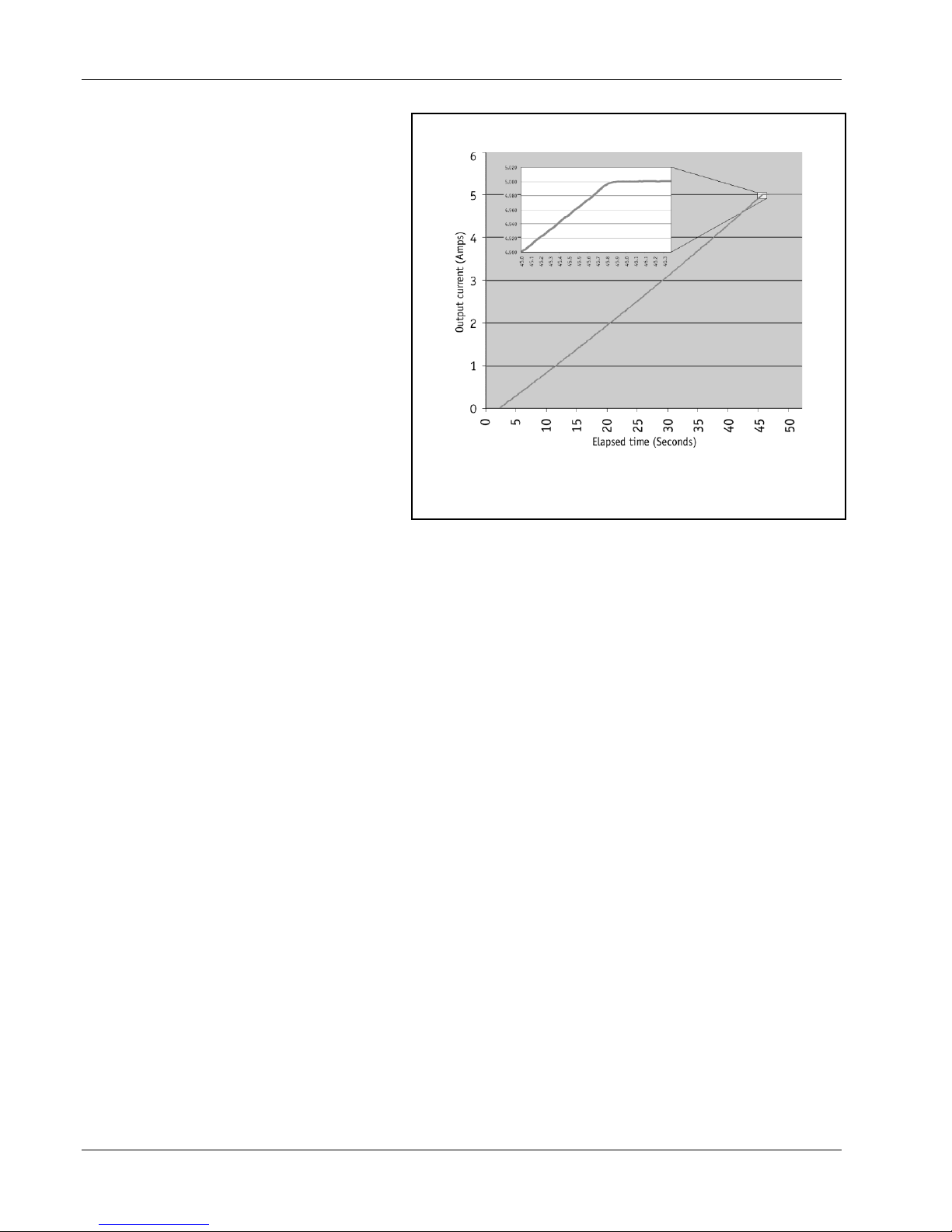
5 Ampere Charge of an 8 Henry Superconducting Magnet*
* 5 A charge of an 8.6 H AMI magnet with a 95 mA/s ramp rate;
output current monitor measured at 58.88 Hz. rate with a HP
34401 – data multiplied by 10× to obtain output current results.
Lake Shore Model 625 Superconducting MPS User’s Manual
At static fields, output current drift is also kept
low by careful attention in the analog control
circuits and layout. The high stability and low
noise of the Model 625 make it possible in many
situations to run experiments without going into
persistent mode. This can help to reduce the time
necessary to gather data.
The Model 625 output architecture relies on low
noise, linear input and output stages. The linear
circuitry of the Model 625 permits operation with
less electrical noise than switch-mode
superconducting magnet power supplies. One key
benefit of this architecture is CE compliance to
the electromagnetic compatibility (EMC)
directive, including the radiated emissions
requirement.
Output Programming
The Model 625 output current is programmed
internally via the keypad or the computer
interface, externally by the analog programming
input, or by the sum of the external and internal
settings. For the more popular internal
programming, the Model 625 incorporates a proprietary digital-to-analog converter (DAC) that is monotonic over the
entire output range and provides a resolution of 0.1 mA.
The Model 625 generates extremely smooth and continuous ramps with virtually no overshoot. The digitally generated
constant current ramp rate is variable between 0.1 mA/s and 99.999 A/s. To ensure a smooth ramp rate, the power supply
updates the high-resolution DAC 28 times per second. A low-pass filter on the DAC output smoothes the transitions at
step changes during ramping. Ramping can also be initiated by the trigger input.
The output compliance voltage of the Model 625 is settable to a value between 0.1 V and 5 V, with a 100 µV resolution.
The voltage is an absolute setting, so a 2 V setting will limit the output to greater than –2.0 V and less than +2.0 V.
Output Readings
The Model 625 provides high-resolution output readings. The output current reading reflects the actual current in the
magnet, and has a resolution of 0.1 mA. The output voltage reading reports the voltage at the output terminals with a
resolution of 100 µV. A remote voltage reading is also available to more accurately represent the magnet voltage by
bypassing voltage drops in the leads connecting the power supply to the magnet. All output readings can be prominently
displayed on the front panel and read over the computer interface.
Protection
Managing the stored energy in superconducting magnets necessitates several different types of protection. The Model
625 continuously monitors the load, line voltage, and internal circuits for signs of trouble. Any change outside of the
expected operating limits triggers the supply to bring the output to zero in a fail-safe mode. When line power is lost, the
output crowbar (SCR) will activate and maintain control of the magnet, discharging at a rate of 1 V until it reaches zero.
Quench detection is necessary to alert the user and to protect the magnet system. The Model 625 uses a basic and reliable
method for detecting a quench. If the current changes at a rate greater than the current step limit set by the operator, a
quench is detected and the output current is safely set to zero.
The remote inhibit input allows an external device to immediately set the output current to zero in case of a failure. This
input is normally tied to an external quench detection circuit, the fault output of a second power supply, or an emergency
shutdown button. The fault output is a relay contact that closes when a fault condition occurs. The contact closure alerts
other system components of the fault.
1-2 Introduction
Lake Shore Model 625 Superconducting MPS User’s Manual
Parallel Operation
If an application requires more output current than a single Model 625 can provide, two supplies can be connected in
parallel for 120 A/5 V operation. Each unit is programmed for half of the total output current, operates independently,
and retains 0.1 mA resolution at 60 A operation. When the units are properly configured, either unit can detect a fault,
protect itself, and issue a fault output signaling the other unit to automatically enter the proper protection mode.
Persistent Switch Heater Output
The integrated persistent switch heater output is a controlled DC current source capable of driving most switch heaters. It
sources from 10 mA to 125 mA with a setting resolution of 1 mA and selectable compliance voltage of 12 V or 21 V.
The minimum load that the persistent switch heater can drive is 10 W. Persistent mode operation is integrated into the
instrument firmware to prevent mis-operation of the magnet.
Interfaces
The Model 625 includes IEEE-488 and RS-232C interfaces that provide access to operating data, stored parameters, and
remote control of all front panel operating functions. In addition, the Model 625 includes a trigger function that is used to
start an output current ramp. When the trigger is activated, either by an external trigger or by computer interface
command, the power supply will begin ramping to the new setpoint.
The Model 625 provides two analog outputs to monitor the output current and voltage. Each output is a buffered,
differential, analog voltage representation of the signal being monitored. The current monitor has a sensitivity of 1 V =
10 A, while the voltage monitor has a sensitivity of 1 V = 1 V.
Display and Keypad
The Model 625 incorporates a large 8-line by 40-character vacuum fluorescent display. Output current, calculated field
in tesla or gauss, output voltage, and remote voltage sense readings can be displayed simultaneously. Five LEDs on the
front panel provide quick verification of instrument status, including ramping, compliance, fault, PSH status, and
computer interface mode. Error conditions are indicated on the main display along with an audible beeper. Extended
error descriptions are available under the Status key.
The keypad is arranged logically to separate the different functions of the instrument. The most common functions of the
power supply are accessed using a single button press. The keypad can be locked to either lock out all changes or to lock
out just the instrument setup parameters allowing the output of the power supply to be changed.
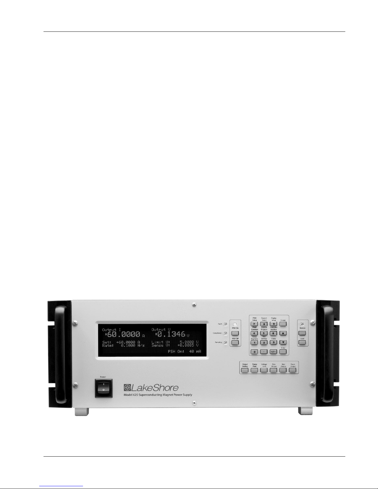
625_Front.bmp
Introduction 1-3
Figure 1-1. Model 625 Front Panel

Lake Shore Model 625 Superconducting MPS User’s Manual
1.2 SPECIFICATIONS
Output
Type: Bipolar, Four Quadrant, DC Current Source
Current Generation: Linear regulation with digital setting and analog control
Current Range: ±60 A
Compliance Voltage: ±5 V maximum (nominal, both source and sink)
Maximum Power: 300 W
Load Reactance: 0 H to 100 H
Current Ripple (Max): 4 mA RMS at 60 A, (0.007%) into 1 m load
(significantly reduced into a reactive load or at lower current)
Current Ripple Frequency: Dominated by line frequency and its harmonics
Temperature Coefficient: ±15 ppm of full scale/°C
Line Regulation: 15 ppm/6% line change
Source Impedance: 25
Stability (1 h): 1 mA/h (after warm-up)
Stability (24 h): 10 mA/24 h (typical, dominated by temperature coefficient and line regulation)
Isolation: Output optically isolated from chassis to prevent ground loops
Parallel Operation: 2 units can be paralleled for ±120 A, ±5 V operation
Protection: Quench, Line Loss, Low Line Voltage, High Line Voltage, Output Over Voltage,
Output Over Current, Over Temperature, Remote Inhibit
(on critical error conditions, magnet discharges at 1 V nominal)
Output Programming
Internal Current Setting
Resolution: 0.1 mA (20 bit)
Settling Time: 600 ms for 1% step to within 0.1 mA into a resistive load
Accuracy: ±10 mA ±0.05% of setting
Operation: Keypad, computer interface
Protection: Current setting limit
Internal Current Ramp
Ramp Rate: 0.1 mA/s to 99.999 A/s (compliance limited)
Update Rate: 27.7 increments/s
Ramp Segments: 5
Operation: Keypad, computer interface, trigger input
Protection: Ramp rate limit
External Current Programming
Sensitivity: 6 V = 60 A
Resolution: Analog
Accuracy: ±10 mA ±1% of setting
Bandwidth (3 dB): 40 Hz, 2-pole, low-pass filter (10 Hz pass band, compliance limited)
Input Resistance: >50 k
Operation: Voltage program through rear panel
Connector: Shared 15-pin D-sub
Limits: Internally clamped at 6.1V
Compliance Voltage Setting
Range: 0.1 V to 5.0 V
Resolution: 100 µV
Accuracy: ±10 mV ±1% of setting
1-4 Introduction

Lake Shore Model 625 Superconducting MPS User’s Manual
Readings
Output Current
Resolution: 0.1 mA
Accuracy: ±1 mA ±0.05% of reading
Update Rate: 2.5 readings/s display, 10 readings/s interface
Compensation: Compensated for lead resistance and 25 source resistance
Output Voltage (at supply terminals)
Resolution: 100 µV
Accuracy: ±1 mV ±0.05% of reading
Update Rate: 2.5 readings/s display, 5 readings/s interface
Remote Voltage (at magnet leads)
Resolution: 100 µV
Accuracy: ±1 mV ±0.05% of reading
Update Rate: 1.25 readings/s
Input Resistance: >50 k
Connector: Shared 15-pin D-sub
Persistent Switch Heater Output (PSHO)
Current Range: 10 mA to 125 mA
Compliance Voltage (minimum): 12 V or 21 V selectable
Heater Resistance (minimum): 10
Setting Resolution: 1 mA
Accuracy: ±1 mA
Operation: On/Off with lockout delay of 5 s to 100 s
Protection: Open or shorted heater detection, error message if off and on output currents differ
Connector: BNC
Front Panel
Display Type: 8-line by 40 character, graphic vacuum fluorescent display module
Display Readings: Output current, calculated field (T or G), output voltage, remote voltage sense
Display Settings: Output current, calculated field, compliance voltage, ramp rate
Display Annunciators: Status and errors
LED Annunciators: PSHO on, remote, compliance limit, fault, ramping
Keypad Type: 26 full travel keys
Keypad Functions: Direct access to common operations, menu driven setup
Interface
IEEE-488.2 Interface
Features: SH1,AH1,T5,L4,SR1,RL1,PP0,DC1,DT1,C0,E1
Reading Rate: To 10 readings/s
Software Support: National Instruments LabVIEW driver (consult Lake Shore for availability)
Serial Interface
Electrical Format: RS-232C
Baud Rates: 9600, 19200, 38400, 57600
Reading Rate: To 10 readings/s
Connector: 9-pin D-sub
Output Current Monitor
Sensitivity: 60 A = 6 V
Accuracy: ±1% of full scale
Noise: 1 mV
Source Impedance: 20
Connector: Shared 15-pin D-sub
Introduction 1-5

Lake Shore Model 625 Superconducting MPS User’s Manual
Output Voltage Monitor
Sensitivity: 1 V = 1 V
Accuracy: ±1% of full scale
Noise: 1 mV
Source Impedance: 20
Connector: Shared 15-pin D-sub
Fault Output
Type: Relay (closed on fault)
Relay Contact: 30 VDC @ 1 A
Connector: Shared 25-pin D-sub
Remote Inhibit Input
Type: TTL or contact closure
Connector: Shared 25-pin D-sub
Trigger Input
Type: TTL or contact closure
Connector: Shared 25-pin D-sub
General
Ambient Temperature: 15 °C to 35 °C
Cooling: Air cooled with internal 2 speed fan
Warm-up: 30 minutes at output current setting
Line Power: 100, 120, 220, 240 VAC +6% –10%, single phase, 50 or 60 Hz, 850 VA
Size: 483 mm W × 178 mm H × 520 mm D (19 in × 7 in × 20.5 in),
rack mount (integrated rack mount ears)
Weight: 27.2 kg (60 lbs)
Approval (pending): CE Mark – Low voltage compliance to EN61010-3, EMC compliance to EN55022-1
Calibration Schedule: 1 year
Ordering Information
Part Number Description
625 Superconducting Magnet Power Supply
625-DUAL Two Model 625s, one dual supply interconnect cable kit
Select a power configuration:
VAC-100-B Instrument configured for 100 VAC with U.S. power cord
VAC-120-B Instrument configured for 120 VAC with U.S. power cord
VAC-120-BC Instrument configured for 120 VAC with U.S. power cord and universal European
power cord and fuses for 220/240 setting (extra charge for this option)
VAC-220-C Instrument configured for 220 VAC with European power cord
VAC-240-C Instrument configured for 240 VAC with European power cord
VAC-220-D Instrument configured for 220 VAC with a 220 V (6-15P) U.S. power cord
Accessories included:
6271 Model 625 user's manual
6241 Two front handles
6242 Two rear handles/protectors
6243 Output shorting bar and terminal fasteners
6251 25-pin D-sub mating connector, digital I/O
6252 15-pin D-sub mating connector, analog I/O
— Calibration Certificate
Accessories available
6201 1 m (3.3 ft) long IEEE-488 (GPIB) computer interface cable assembly
6261 10 ft – 60 A magnet cable kit, AWG 4
6262 20 ft – 60 A magnet cable kit, AWG 4
6263 Dual supply interconnect cable kit (including magnet cables and safety interlock cable)
CAL-625-CERT Instrument recalibration with certificate
CAL-625-DATA Instrument recalibration with certificate and data
1-6 Introduction
• Indoor use.
• Altitude to 2000 meters.
• Temperature for safe operation: 5 °C to 40 °C.
• Overvoltage category II.
• Pollution degree 2.
• Maximum relative humidity: 80% for temperature up to
31 °C decreasing linearly to 50% at 40 °C.
• Power supply voltage fluctuations not to exceed ±10%
of the nominal voltage.
Lake Shore Model 625 Superconducting MPS User’s Manual
1.3 SAFETY SUMMARY
Observe these safety precautions during all phases of instrument operation, service, and repair. Failure to comply with
these precautions or with specific warnings elsewhere in this manual violates safety standards of design, manufacture,
and intended instrument use. Lake Shore assumes no liability for Customer failure to comply with these requirements.
The Model 625 protects the operator and surrounding area from electric shock or burn, mechanical hazards, excessive
temperature, and spread of fire from the instrument. Environmental conditions outside of the conditions below may pose
a hazard to the operator and surrounding area.
Ground The Instrument
To minimize shock hazard, the instrument is equipped with a 3-conductor AC power cable. Plug the power cable into
an approved three-contact electrical outlet or use a three-contact adapter with the grounding wire (green) firmly
connected to an electrical ground (safety ground) at the power outlet. The power jack and mating plug of the power
cable meet Underwriters Laboratories (UL) and International Electrotechnical Commission (IEC) safety standards.
Ventilation
The instrument has ventilation holes in its side covers. Do not block these holes when the instrument is operating.
Do Not Operate In An Explosive Atmosphere
Do not operate the instrument in the presence of flammable gases or fumes. Operation of any electrical instrument in
such an environment constitutes a definite safety hazard.
Keep Away From Live Circuits
Operating personnel must not remove instrument covers. Refer component replacement and internal adjustments to
qualified maintenance personnel. Do not replace components with power cable connected. To avoid injuries, always
disconnect power and discharge circuits before touching them.
Do Not Substitute Parts Or Modify Instrument
Do not install substitute parts or perform any unauthorized modification to the instrument. Return the instrument to an
authorized Lake Shore representative for service and repair to ensure that safety features are maintained.
Cleaning
Do not submerge instrument. Clean only with a damp cloth and mild detergent. Exterior only.
Moving and Handling
Four handles are provided for ease of moving and handling the Model 625. Always use at least two, and if possible
four, handles when carrying the unit.
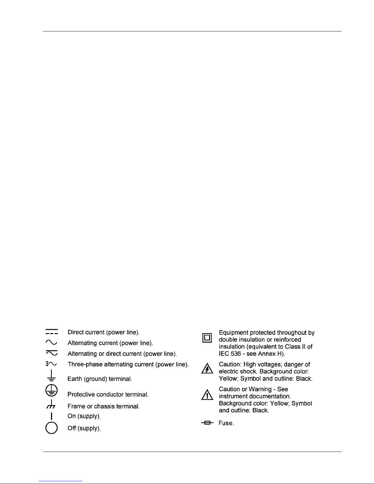
1.4 SAFETY SYMBOLS
Introduction 1-7

Lake Shore Model 625 Superconducting MPS User’s Manual
This Page Intentionally Left Blank
1-8 Introduction

Lake Shore Model 625 Superconducting MPS User’s Manual
CHAPTER 2
MAGNET SYSTEM DESIGN
2.0 GENERAL
This chapter provides information on general magnet system design. It is intended to give the user insight into
superconducting materials, superconducting magnets, persistent switches, dewars, and cabling issues. For information on
how to install the Model 625 please refer to Chapter 3. Instrument operation information is contained in Chapter 4.
2.1 SUPERCONDUCTING MATERIALS
Superconducting materials have a very special property, that when cooled to very low temperatures, they become perfect
conductors of electricity. The transition to the superconducting state happens abruptly as the critical temperature is
reached. When the material is in its superconducting state, it has absolutely zero resistance. Such materials have a variety
of applications, one of which is for the construction of high field magnets.
The unique properties of superconductors make them ideal for use in high field magnets. Since a superconductor has no
resistance it requires no voltage to maintain a current through it. Magnet grade superconductors also have a very high
current density allowing a relatively small wire to carry a large amount of current that can be used to generate large
magnetic fields.
There are three properties that determine if a material is in its superconducting state. The first property is critical
temperature. A superconductor needs to be cooled in order to transition to a superconducting state. This temperature is
called its critical temperature. Most materials need to be cooled with liquid helium in order to reach their critical
temperatures although some ceramics have shown to have a critical temperature as high as 125 K which would be
suitable for nitrogen cooling.
The second property is critical current density. A superconducting wire can only carry a certain amount of current in its
superconducting state. The current density of a typical superconducting wire made from niobium-titanium is on the order
of 1010 A/m2, about three orders of magnitude greater than normal house wiring. If the critical current density is
exceeded, the wire will return to its normal resistive state.
The last property is critical field. A superconductor will return to its normal resistive state if it is exposed to a magnetic
field larger than its critical field. Superconducting wire such as niobium-titanium and niobium-tin have critical fields in
excess of 10 T and 20 T respectively. Elemental superconductors, such as lead, have very low critical fields, in this case
0.08 T, and are not suited for creating superconducting magnets.
All three of these properties are related to one another. For instance, a superconducting wire is able to carry more current
and withstand a higher magnetic field as it is cooled to a lower temperature. In the case of niobium-titanium, a common
superconducting wire, the critical temperature is 9.3 K but at that temperature both the critical field and critical current
density are both zero. At a temperature of 6 K, the critical field increases to approximately 7 T and at 4 K it is
approximately 11 T.
2.2 SUPERCONDUCTING MAGNETS
Superconducting magnets are wound from many turns of superconducting wire. They are used to generate magnetic
fields that are larger than can be achieved with permanent magnets or electromagnets or when field stability is important.
They can also be more economical to run than electromagnets since the power needed to maintain the charge is minimal.
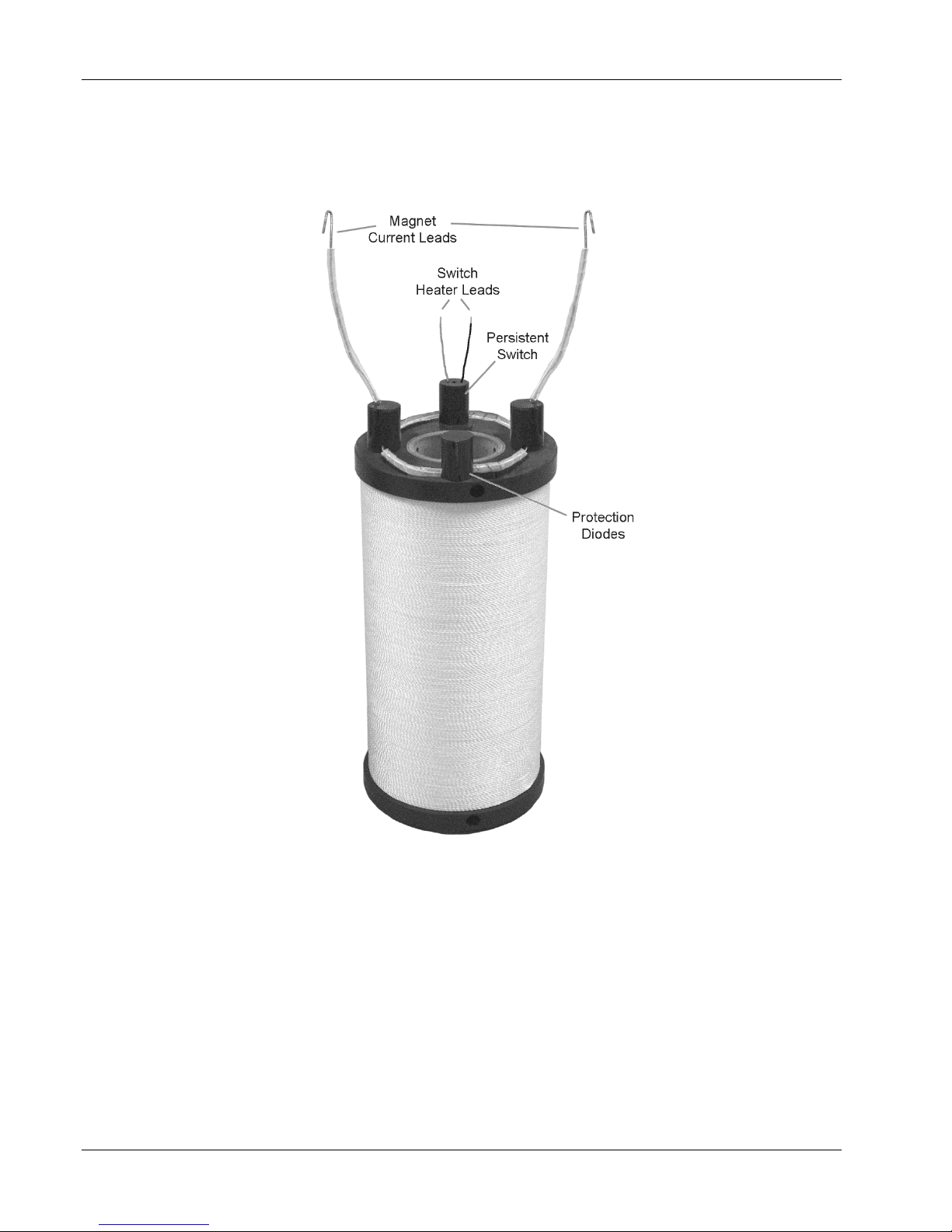
2.2.1 Superconducting Magnet Construction
The magnetic field (B) that can be generated by a solenoid is given by the equation B=μ0In/l, where μ0 is the
permeability of air, I is the current in the wire, n is the number of turns, and l is the length of the solenoid. Most
superconducting magnets are wound using a conductor made from many fine strands of niobium-titanium (NbTi) or
niobium-tin (Nb3Sn) embedded in a copper matrix. The copper matrix is used for mechanical stability and to provide a
path for large currents in the case of a magnet quench. Typically, niobium-tin is only used in magnets that can generate
fields in excess of 9 Tesla because it is more expensive and harder to work with than niobium-titanium.
Magnet System Design 2-1
Lake Shore Model 625 Superconducting MPS User’s Manual
The superconducting wire is wound around a non-magnetic former made from aluminum, brass, stainless steel, or other
material as needed. The individual windings are electrically insulated by the insulation on the wire and by an epoxy that
is applied to the windings. The epoxy is also necessary to keep the individual windings from moving when the magnet is
charged.
Figure 2-1. Typical Superconducting Magnet
2.2.2 Magnet Inductance
The inductance of a solenoid (L) is defined as L = μ0n2A/l, where μ0 is the permeability of air, n is the number of turns, A
is the cross sectional area of the coil, and l is the length of the solenoid. The inductance of superconducting magnets is
fairly large, typically between 10 and 100 Henries. The magnet’s inductance limits the rate at which the magnet can be
charged or discharged because of the increased voltage required to change current. The formula V = L (di/dt) relates
charging voltage to inductance where V is the charging voltage, L is the magnet inductance, and di/dt is the rate of
change in current. The Model 625 can charge a magnet up to a 5 V rate, although many magnets are not designed to be
charged at that rate. For instance, a 10 Henry magnet can be charged at a rate of 0.5 A/s with a 5 V limit. A rate of 0.1
A/s is more typical.
2-2 Magnet System Design

Lake Shore Model 625 Superconducting MPS User’s Manual
The resistance of the leads must be taken into account when calculating charge rate since a voltage drop across the leads
will limit the voltage that can be delivered to the terminals of the magnet. This becomes especially important as the
charging current rises since the voltage drop across the leads will increase.
2.2.3 Maximum Ramp Rate
Not only is the rate at which a magnet can be charged limited to the magnet’s inductance but it is also limited by the
magnet’s construction. When a magnet is charged or discharged, heat is generated in the coils. The faster the ramp rate,
the more heat that will be generated. If the heat cannot be conducted out of the magnet fast enough, a section of the
superconducting windings can go normal and cause a quench. The magnet manufacturer should state the maximum ramp
rate of the magnet. In some magnets, the current cannot be changed at the same rate over the entire current range of the
magnet. These magnets need to be charged at a slower rate as they reach their maximum current rating.
2.2.4 Maximum Magnet Current
Although superconducting wire can carry more current than non-superconducting wire of the same size, the amount of
current that it can carry is not unlimited. If the critical current of the wire is exceeded, the wire will no longer be
superconducting and will revert to its normal state causing the magnet to quench. Commercially purchased magnets have
been designed to work up to a maximum stated current. The magnet should be able to handle a quench up to the rated
current of the magnet. Do not exceed the maximum current rating of the magnet or the magnet can quench and possibly
be damaged.
2.2.5 Magnet Quench Protection Diodes
Many superconducting magnets have protection diodes installed across the terminals of the magnet. These diodes will
turn on in the event of a quench and will help dissipate some of the magnets energy. Typically the diodes are attached to
the magnet itself and are submerged in the cryogen. At 4.2 K the forward voltage of the diodes may be on the order of 10
volts. If the magnet quenches, the energy dissipated in the diodes will warm them, resulting in a decrease in their forward
voltage. If this voltage drops below the compliance voltage limit of the power supply, the power supply will continue to
source current to the diodes eventually damaging them and causing them to short. This would require that the protection
diodes be replaced which could be a significant expense especially if the magnet is in a sealed dewar.
To ensure that the diodes are not damaged by the power supply, the compliance voltage limit of the supply should be set
to a voltage below the protection diode range. It is also recommended that some form of quench detection be used to
force the output of the power supply to 0 amps when a quench is detected ensuring that no additional current is being
supplied to the diodes. The Model 625 offers both internal quench detection and a remote inhibit line that can be
connected to an external quench detection circuit.
2.3 PERSISTENT SWITCHES
Some superconducting magnets are constructed with a persistent switch. A persistent switch is a length of
superconducting wire that shorts across the terminals of the magnet. This length of wire can be heated and drives it into a
resistive state so that a voltage can be applied across the magnet terminals and the magnet can be charged or discharged.
When the heater is shut off, this section of wire will cool and become superconducting again and the magnet will be in
persistent mode. At this time, the power supply can be ramped to zero current and even removed from the system while
the magnet holds its charge.
One of the reasons to use a persistent switch is when a very stable field is required. When the magnet is in persistent
mode, all of the current is being circulated within the magnet with no interference from outside sources. Another reason
to use a persistent switch is when it is desired to hold a particular magnet field for an extended period of time, such as in
a MRI system. Once the magnet is in persistent mode, the power supply can be removed from the system and used
elsewhere. It is also possible on some systems to remove the vapor cooled leads from the dewar to further reduce the
amount of helium boil off.
The magnet manufacturer will specify the current necessary to turn on the persistent switch heater. Do not use any more
current than is necessary since that will result in excess helium boil off. It is important when turning on the persistent
switch heater that the current setting of the power supply is equal to the current in the magnet. If the current does not
match, the current in the magnet will ramp to the current setting of the power supply at the compliance voltage limit.
This may cause the power supply to incorrectly detect a quench.
Magnet System Design 2-3
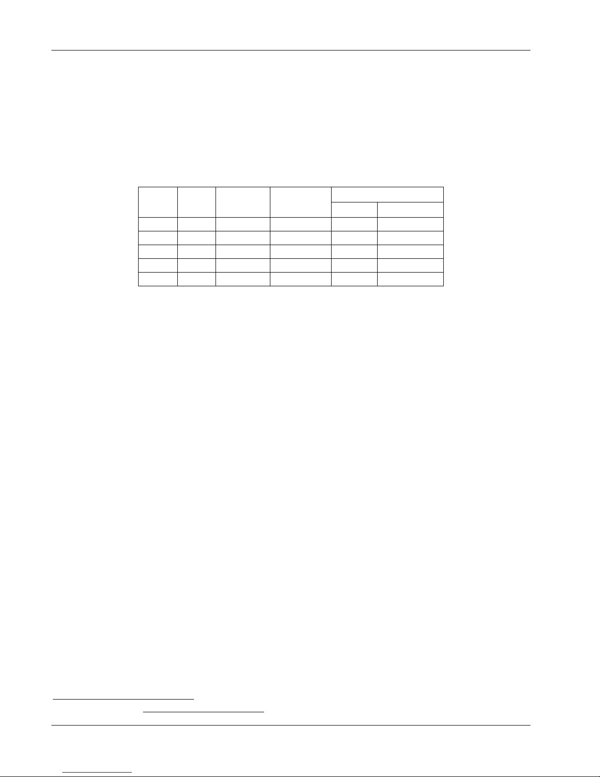
AWG
Area
(mm2)
Capacity
(A)
Resistivity
/1000 feet
Total Lead Length (feet)
60 A
120 A
0
53.5
245
0.09827
170
85
2
33.6
180
0.1563
107
53
4
21.2
135
0.2485
67
34
6
13.3
100
0.3951
42
—
8
8.4
75
0.6282
27
—
1
Lake Shore Model 625 Superconducting MPS User’s Manual
2.4 MAGNET CURRENT LEADS
The power supply should be placed close to the magnet to reduce the length of the lead wires. The resistance of the wires
becomes very important when such large currents are being supplied to the magnet. The rate at which a magnet can be
charged depends on the voltage that can be supplied across the terminals of the magnet given by the equation V = L
(di/dt). The voltage is limited by the maximum voltage the power supply can output minus the voltage that is lost
through the magnet leads. Use lead wires heavy enough to limit the voltage drop to less than 0.5 volts per lead and keep
conductor temperature under 85 °C for a 35 °C ambient temperature. Table 2-1 lists the current capacity and total lead
lengths for load connections.
Table 2-1. Current Capacity and Total Lead Lengths
The Remote Voltage Sense connection can be used to monitor the voltage directly across the terminals of the magnet.
This will give a more accurate voltage reading across the terminals of the magnet by eliminating the voltage drop in the
leads. Some magnets manufacturers provide voltage sense connections directly at the terminals of the magnet. If these
are not available, they can be added and the signals can be brought out of the dewar to be connected to the power supply.
If it is not desirable to add wiring inside the dewar, the sense leads can be connected to the magnet current leads at the
dewar. The remote voltage sense input can only be used to read the voltage at the magnet terminals and cannot be used to
control the voltage limit.
2.5 HELIUM DEWARS1
Since superconducting magnets need to be run at cryogenic temperatures, they are installed in dewars filled with liquid
helium. A dewar usually consists of one or more reservoirs surrounded by a vacuum jacket. This vacuum jacket insulates
the reservoir from room temperatures. In dewars with multiple reservoirs, the outside reservoir is normally filled with
liquid nitrogen as a way to further reduce the heat transfer from the liquid helium filled inner reservoir. Most dewars are
made from stainless steel although they can also be made from glass or epoxy-fiberglass and aluminum. Stainless steel is
used because it is very rugged, has low thermal conductivity, and can easily be welded to different types of metals.
The most basic dewars are of an all welded construction with an opening in the top for direct access to the cryogen
reservoir. The dewar will have an evacuation valve to evacuate the vacuum jacket surrounding the cryogen reservoir.
There will also be a pressure relief valve to protect the vacuum jacket in case a leak should develop. This leak would
allow cold cryogen into the vacuum jacket where it will expand upon contact with the room temperature wall. This
pressure relief valve is set to open between 2 and 5 psi to safely vent the leaking gas.
The superconducting magnet can either be supported by the insert or supported by a base in the bottom of the dewar. If
the magnet is in the base of the dewar, it is usually installed when the dewar is built and can only be removed or serviced
by cutting the dewar apart. Any insert that is placed in the helium reservoir should contain a number of radiation baffles
in the neck region of the dewar. These baffles are normally made from copper and are cooled by the escaping helium
gas. This will help cut down on radiation losses from the room temperature top flange on the insert. It will also help to
cut down on conductive heat loss being transferred down the neck of the dewar. The high current leads used for charging
the magnet should be vapor cooled to reduce the amount of heat that is transferred into the helium reservoir.
Information gathered from Introduction to Laboratory Cryogenics, M.N. Jirmanus, Janis Research Company, Inc.
2-4 Magnet System Design

Lake Shore Model 625 Superconducting MPS User’s Manual
With the magnet submerged in liquid helium, it will be at a temperature of 4.2 K at atmospheric pressure. Some magnets
are rated to work at 2.2 K allowing a larger field to be generated. This temperature can be achieved by lowering the
pressure over the helium reservoir thereby lowering the boiling point of the helium. Some dewars will have a pumping
port that can be attached to a vacuum pump to reduce the pressure and lower the temperature but will increase the rate of
liquid helium consumption.
The amount of energy that can be stored in a magnet is given by the equation E = ½LI2. Typical laboratory magnets have
inductances of 10 to 100 Henries and can have maximum currents of 40 to 120 Amps. The energy stored in a typical
magnet can be anywhere from a few thousand Joules to over one hundred thousand Joules. In the case of a magnet
quench, all of this energy is going to be dumped into the liquid helium within a matter of a few seconds creating a large
amount of helium gas. Any dewar that is used with a superconducting magnet should have a pressure relief port on the
helium reservoir to allow the helium gas to be dissipated in the case of a quench.
The level of the liquid helium can be monitored by using a liquid helium level sensor installed in the dewar. The level of
the helium should never be allowed to drop below the top of the magnet while the magnet is in operation. Allowing the
magnet to become uncovered can cause a quench. Also, the level of the helium should never be higher than the inlets of
the vapor cooled current leads. If the inlets are submerged in liquid helium, the helium gas can no longer cool the leads
and extra heat will be transferred into the helium reservoir increasing the rate of helium boil off.
2.6 MAGNET QUENCH
A magnet quench occurs when part of the superconducting wire in the magnet becomes normal and has resistance. When
a section of the magnet becomes resistive it will begin to heat and will cause more of the magnet to become resistive.
This causes an unstoppable chain reaction that will result in the magnet dissipating all of its energy into heat. This can
happen if the critical temperature, critical current, or critical field are exceeded. Refer to Paragraph 2.1 for a description
of superconductor properties. Even though a quench is not necessarily destructive to the magnet, it should be avoided at
all costs. Always check the level of liquid helium and make sure that the magnet is completely covered before operating
the magnet. Never ramp a magnet at a ramp rate greater than what is specified by the magnet manufacturer. Never
exceed the current rating of the magnet since a quench in this case can easily damage the magnet.
Typically the current in the magnet will be completely dissipated in about a half of a second causing the magnet to heat.
It may then take several minutes before the liquid helium cools the magnet back to its superconducting state. Since a
quench can boil off a significant amount of helium, always check the helium level before operating the magnet after a
quench.
Magnet System Design 2-5
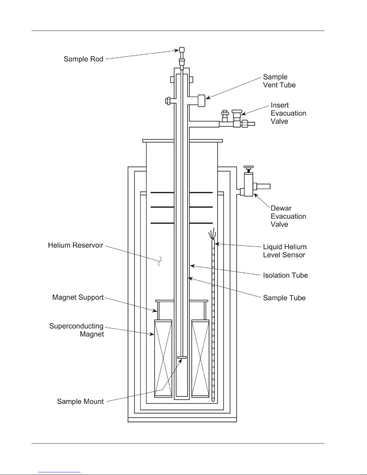
Lake Shore Model 625 Superconducting MPS User’s Manual
Figure 2-2. Cutaway Of A Typical Helium Dewar, Magnet, and Insert
2-6 Magnet System Design

Lake Shore Model 625 Superconducting MPS User’s Manual
CHAPTER 3
INSTALLATION
3.0 GENERAL
This chapter provides general installation instructions for the Model 625 Superconducting Magnet Power Supply. Please
read this entire chapter before installing the instrument and powering it on to ensure the best possible performance and
maintain operator safety. For instrument operating instructions refer to Chapter 4. For computer interface installation and
operation refer to Chapter 6.
NOTE: It is recommended that the instrument be powered up and operated with the shorting bar in place before
connecting it to a magnet. This will allow the user to setup the supply and become comfortable with its
operation without risk of damage to the magnet.
3.1 INSPECTION AND UNPACKING
Inspect shipping containers for external damage before opening them. Photograph any container that has significant
damage before opening it. If there is visible damage to the contents of the container contact the shipping company and
Lake Shore immediately, preferably within 5 days of receipt of goods. Keep all damaged shipping materials and contents
until instructed to either return or discard them.
Open the shipping container and keep the container and shipping materials until all contents have been accounted for.
Check off each item on the packing list as it is unpacked. Instruments themselves may be shipped as several parts. The
items included with the Model 625 are listed below. Contact Lake Shore immediately if there is a shortage of parts or
accessories. Lake Shore is not responsible for any missing items if not notified within 60 days of shipment.
Inspect all items for both visible and hidden damage that occurred during shipment. If damage is found, contact Lake
Shore immediately for instructions on how to file a proper insurance claim. Lake Shore products are insured against
damage during shipment but a timely claim must be filed before Lake Shore will take further action. Procedures vary
slightly with shipping companies. Keep all shipping materials and damaged contents until instructed to either return or
discard them.
If the instrument must be returned for recalibration, replacement or repair, a returned goods (RA) number must be
obtained from a factory representative before it is returned. The Lake Shore RA procedure is given in Paragraph 7.2.
Items Included with Model 625 Superconducting Magnet Power Supply
1 Model 625 Instrument
1 Model 625 User’s Manual
2 Front Handles
2 Rear Handles
1 Digital I/O Mating Connector
1 Analog I/O Mating Connector
1 Output Shorting Bar and Terminal Fasteners (Installed on output bus bars)
1 Line Power Cord
1 Fuse Pair for Alternative Voltage *
1 Line Power Cord for Alternative Voltage *
* Included only when purchased with VAC-120-ALL Power Option.
3.1.1 Moving and Handling
Four handles are provided for ease of moving and handling the Model 625. Always use at least two, and if possible four,
handles when carrying the unit.
Installation 3-1
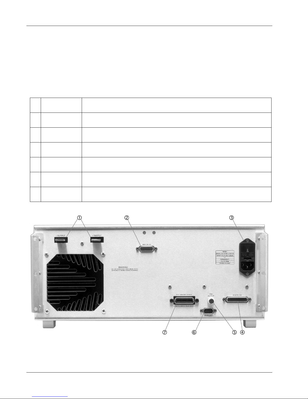
–OUTPUT
+OUTPUT
Two bus bars for the magnet cable connections. Refer to Paragraph 3.4 for connecting the
magnet cables to the instrument.
ANALOG I/O
15-pin D subminiature receptacle provides analog monitor outputs as well as analog inputs.
Refer to Paragraph 3.5 and see Figure 7-4.
Line Input
Assembly
Includes the IEC 320-C14 line cord receptacle and line voltage selector with line voltage
indicator and line fuse holder. Refer to Paragraph 3.3.
DIGITAL I/O
25-pin D subminiature receptacle provides connections for digital inputs and outputs.
Refer to Paragraph 3.6 and see Figure 7-6.
PSH OUTPUT
BNC receptacle provides connections for the Persistent Switch Heater. Refer to
Paragraph 3.7 and see Figure 7-5.
RS-232 (DTE)
9-pin D subminiature plug wired in DTE configuration for use with RS-232C serial
computer interface. Refer to Paragraph 5.2.2 and see Figure 7-7.
IEEE-488
INTERFACE
IEEE-488 compliant interface connector for use with IEEE-488 parallel computer
interface. Refer to Paragraph 5.1 and see Figure 7-8.
Lake Shore Model 625 Superconducting MPS User’s Manual
3.2 REAR PANEL DEFINITION
This paragraph defines the rear panel of the Model 625. See Figure 3-1. Readers are referred to paragraphs that contain
installation instructions and connector pin-outs for each feature. A summary of connector pin-outs is provided in
Paragraph 7.12.
CAUTION: Verify that the AC line voltage indicator in the fuse drawer window shows the appropriate AC line
voltage before turning he instrument on.
CAUTION: Make rear panel connections with the instrument power off.
625_Rear.bmp
Figure 3-1. Model 625 Rear Panel
3-2 Installation
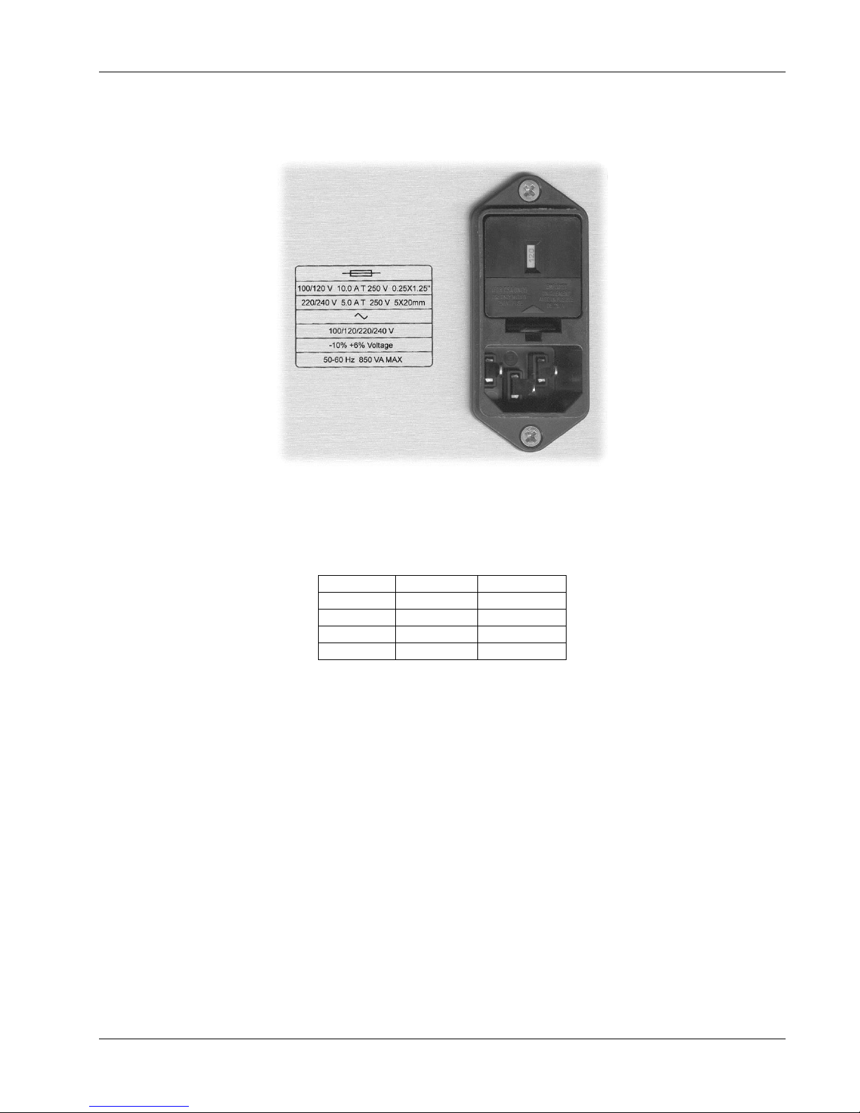
Nominal
Minimum
Maximum
100 V
90 V
106 V
120 V
108 V
127 V
220 V
198 V
233 V
240 V
216 V
254 V
Lake Shore Model 625 Superconducting MPS User’s Manual
3.3 LINE INPUT ASSEMBLY
This section describes how to properly connect the Model 625 to line power. Please follow these instructions carefully to
ensure proper operation of the instrument and the safety of operators.
Line_Input.bmp
Figure 3-2. Line Input Assembly
3.3.1 Line Voltage
The Model 625 has four different AC line voltages configurations so that it can be operated from line power anywhere in
the world. The nominal voltage and voltage range of each configuration is shown below. (The recommended setting for
230 V operation is 240 V.)
Verify that the AC line voltage indicator in the fuse drawer window shows the appropriate AC line voltage before
turning the instrument on. The instrument may be damaged if it is turned on with the wrong voltage selected. Instructions
for changing the line voltage configuration are given in Paragraph 7.4.
3.3.2 Line Fuse and Fuse Holder
The line fuse is an important safety feature of the Model 625. If a fuse ever fails, it is important to replace it with the
value and type indicated on the rear panel for the line voltage setting. The letter T on the fuse rating indicates that the
instrument requires a time-delay or slow-blow fuse. Fuse values should be verified any time line voltage configuration is
changed. Instructions for changing and verifying a line fuse are given in Paragraph 7.5.
3.3.3 Power Cord
The Model 625 includes a 3-conductor power cord that mates with the IEC 320-C14 line cord receptacle. Line voltage is
present on the two outside conductors and the center conductor is a safety ground. The safety ground attaches to the
instrument chassis and protects the user in case of a component failure. A CE approved power cord is included with
instruments shipped to Europe; a domestic power cord is included with all other instruments (unless otherwise specified
when ordered). Always plug the power cord into a properly grounded receptacle to ensure safe operation of the
instrument.
The delicate nature of measurement being taken near this instrument may necessitate additional grounding including
ground strapping of the instrument chassis. In these cases the operators safety should remain the highest priority and low
impedance from the instrument chassis to safety ground should always be maintained.
Installation 3-3
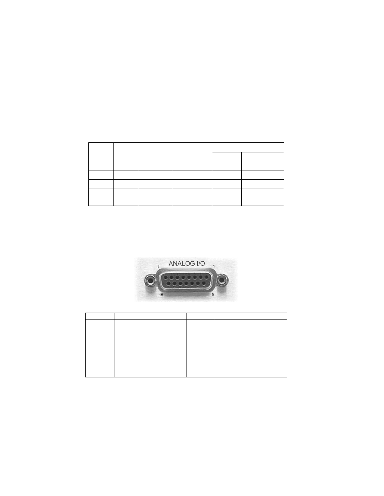
AWG
Area
(mm2)
Capacity
(A)
Resistivity
/1000 feet
Total Lead Length (feet)
60 A
120 A
0
53.5
245
0.09827
170
85
2
33.6
180
0.1563
107
53
4
21.2
135
0.2485
67
34
6
13.3
100
0.3951
42 — 8
8.4
75
0.6282
27
—
Pin
Name
Pin
Name
1
2
3
4
5
6
7
8
Voltage Sense –
NC
Current Program –
NC
Voltage Monitor –
NC
Current Monitor –
NC
9
10
11
12
13
14
15
Voltage Sense +
NC
Current Program +
NC
Voltage Monitor +
NC
Current Monitor +
3.3.4 Power Switch
Lake Shore Model 625 Superconducting MPS User’s Manual
The power switch is on the front panel of the Model 625 and turns line power to the instrument On and Off. When the
circle is depressed, power is Off. When the line is depressed, power is On.
3.4 MAGNET CABLE CONNECTIONS
Magnet cable connections are made at the +OUTPUT and –OUTPUT terminals on the rear panel. These plated copper
bus bars accommodate ¼ inch (M6) mounting hardware. Use load wires heavy enough to limit the voltage drop to less
than 0.5 volts per lead. This ensures proper regulation and prevents overheating while carrying the output current. The
remote voltage sense leads can be used to measure the actual magnet voltage. Keep conductor temperature under 85 °C
(185 °F) for a 35 °C (95 °F) ambient. Table 3-1 lists the current capacity and total lead lengths for load connections.
Lake Shore sells magnet cables in 10 and 20 foot lengths. Refer to Paragraph 6.2 for ordering accessories.
Table 3-1. Current Capacity and Total Lead Lengths
3.5 ANALOG INPUT/OUTPUT CONNECTIONS
The Analog I/O connector provides connections to analog signals used to monitor or control the power supply. Two
inputs are provided, one to program the current output and one used to monitor the remote voltage sense leads. Two
outputs are also provided to monitor the output current and the output voltage. Refer to the instrument specifications in
Paragraph 1.2 for input and source impedances.
Analog_Output.bmp
Figure 3-3. Model 625 Analog Input/Output Connector
3.5.1 External Current Programming
The output current can be programmed externally using an analog voltage. This programming voltage can also be
summed with the internal current setting. Refer to Paragraph 4.18 to change the external program mode. The external
current programming input is a differential input with a sensitivity of 1 V = 10 A and an input impedance of > 50 k.
The programming voltage is limited internally to approximately ±6.1 V but care must be taken to insure that maximum
current capability of the magnet is never exceeded.
3-4 Installation
 Loading...