

Page 1
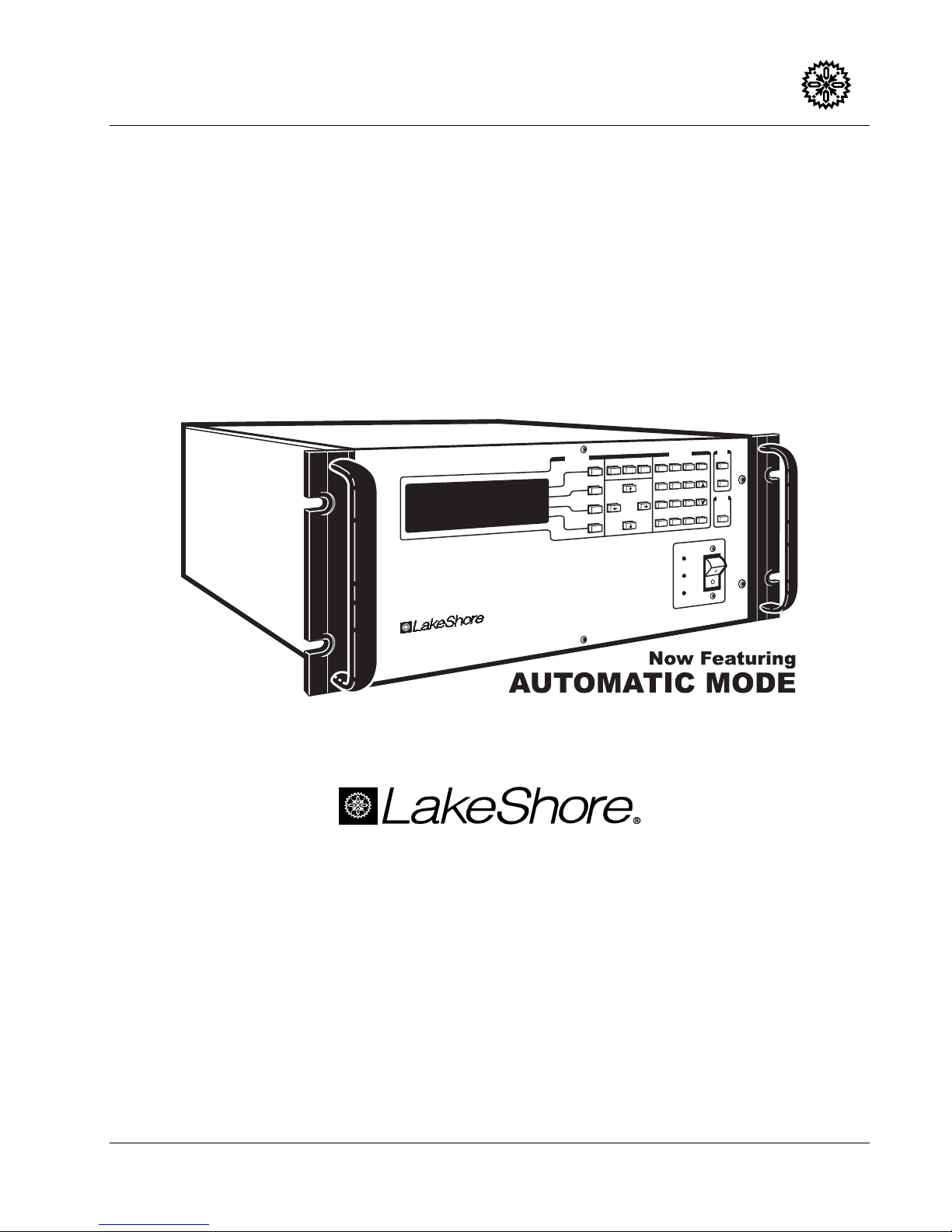
User’s Manual
Model 620/622/623/647
Model 620/622/623/647
Model 620/622/623/647Model 620/622/623/647
Model 620 – ±50 A, ±5 V Model 623 – ±155 A, ±30 V
Model 622 – ±125 A, ±30 V Model 647 – ±72 A, ±32 V
s
n
tio
c
n
u
F
Magnet Power Supply
Normal
Next
Function
Display
Menu
Menu
7
7
4
1
Cursor
0
Magnet Power Supply
D
ata
8
8
5
2
.
Switch Heater
E
Persistent
e
d
o
M
ntry
l
l
a
c
o
ca
L
o
L
c
s
E
c
s
E
9
9
e
t
o
m
e
R
6
t
u
tp
u
O
it
ib
h
In
3
Enter
+/-
Power
Fault
Methods and apparatus disclosed and described herein have been developed solely on company funds of Lake Shore Cryotronics, Inc.
No government or other contractual support or relationship whatsoever has existed which in any way affects or mitigates proprietary
rights of Lake Shore Cryotronics, Inc. in these developments. Methods and apparatus disclosed herein may be subject to U.S. Patents
existing or applied for. Lake Shore Cryotronics, Inc. reserves the right to add, improve, modify, or withdraw functions, design
modifications, or products at any time without notice. Lake Shore shall not be liable for errors contained herein or for incidental or
consequential damages in connection with furnishing, performance, or use of this material.
Rev. 1.2 P/N 119-001 9 April 1999
Lake Shore Cryotronics, Inc.
575 McCorkle Blvd.
Westerville, Ohio 43082-8888 USA
E-Mail Addresses:
Visit Our Website:
www.lakeshore.com
Fax: (614) 891-1392
Telephone: (614) 891-2243
Page 2

Lake Shore Model 620/622/623/647 Magnet Power Supply User’s Manual
LIMITED WARRANTY
Lake Shore Cryotronics, Inc. (henceforth Lake Shore), the manufacturer, warrants the instrument to be free
from defects in material and workmanship for a period of twelve months from the date of shipment. During the
warranty period, under authorized return of instruments or component parts to Lake Shore freight prepaid, the
company will repair, or at its option replace, any part found to be defective in material or workmanship, without
charge to the Owner for parts, service labor or associated customary shipping cost. Replacement or repaired
parts will be warranted for only the unexpired portion of the original warranty.
All products are thoroughly tested and calibrated to published specifications prior to shipment. Calibration
Certifications are offered for six month periods only. Where such documentation must be updated, a
re-certification service is offered by Lake Shore at a reasonable cost.
LIMITATION OF WARRANTY
This warranty is limited to Lake Shore products purchased and installed in the United States, or Internationally
through our approved distribution agents. This same protection will extend to any subsequent owner during
the warranty period. It does not apply to damage resulting from improper or inadequate maintenance,
unauthorized modification or misuse, operation outside of the environmental specifications, or from buyersupplied software interfacing. It does not apply to damage caused by accident, misuse, fire, flood or Acts of
God, or from failure to properly install, operate, or maintain the product in accordance with the printed
instruction provided.
This warranty is in lieu of any other warranties, expressed or implied, including merchantability or fitness for a
particular purpose, which are expressly excluded. the owner agrees that Lake Shore’s liability with respect to
this product shall be set forth in this warranty, and incidental or consequential damages are expressly
excluded.
CERTIFICATION
Lake Shore certifies that this product has been inspected and tested in accordance with its published
specifications and that this product met its published specifications at the time of shipment. The accuracy and
calibration of this product at the time of shipment are traceable to the United States National Institute of
Standards and Technology (NIST); formerly known as the National Bureau of Standards (NBS), or to a
recognized natural standard.
TRADEMARK ACKNOWLEDGMENT
Many manufacturers and sellers claim designations as trademarks to distinguish their products. Where those
designations appear in this manual and Lake Shore was aware of a trademark claim, they appear with initial
capital letters and a proceeding ™ or
®
symbol.
CalCurve™, Carbon-Glass™, Cernox™, Duo-Twist™, Gamma Probe™, Quad-Lead™,
and Quad-Twist™ are trademarks of Lake Shore Cryotronics, Inc.
®
Kapton
Stycast
Teflon
QuickBasic
is a trademark of 3M.
®
is a trademark of Emerson & Cuming.
®
is a trademark of DuPont De Nemours.
®
is a trademark of Microsoft Corporation.
Copyright © 1995 – 1999 by Lake Shore Cryotronics, Inc. All rights reserved. No portion of this manual may be
reproduced, stored in a retrieval system, or transmitted, in any form or by any means, electronic, mechanical,
photocopying, recording, or otherwise, without the express written permission of Lake Shore.
A
Page 3

Lake Shore Model 620/622/623/647 Magnet Power Supply User’s Manual
TABLE OF CONTENTS
Chapter/Paragraph Title Page
List of Illustrations ......................................................................................................................................iv
List of Tables..............................................................................................................................................iv
Foreword .................................................................................................................................................... v
Purpose and Scope ................................................................................................................................ v
Hardware Covered.................................................................................................................................. v
Warnings, Cautions, and Notes .............................................................................................................. v
General Installation Precautions ............................................................................................................. v
Electrostatic Discharge ........................................................................................................................... v
Handling Electrostatic Discharge Sensitive Components....................................................................vi
Safe Handling of Liquid Cryogens .......................................................................................................vi
Magnet Quenches ...............................................................................................................................vi
Dangerous Voltages ...............................................................................................................................vi
Before You Operate the Equipment.......................................................................................................vii
Safety Summary ....................................................................................................................................vii
Safety Symbols .....................................................................................................................................viii
1 INTRODUCTION ....................................................................................................................................1-1
1.0 General ...................................................................................................................................1-1
1.1 Features.................................................................................................................................. 1-1
1.2 Specifications..........................................................................................................................1-2
1.3 Operating Characteristics ....................................................................................................... 1-4
1.3.1 True, Four-Quadrant Bidirectional Power Flow ...................................................................1-4
1.3.2 Low Noise, High Stability Current Regulated Output...........................................................1-5
1.3.3 Highly Efficient, Air-Cooled, Compact Unit ..........................................................................1-5
2 INITIAL SETUP AND CONNECTIONS ..................................................................................................2-1
2.1 Inspecting and Unpacking ......................................................................................................2-1
2.2 MPS Mounting ........................................................................................................................ 2-1
2.3 Environmental Requirements .................................................................................................2-1
2.4 Connecting the MPS to Power................................................................................................2-1
2.4.1 Power and Ground Requirements .......................................................................................2-2
2.4.2 MPS Input Power Ratings....................................................................................................2-2
2.4.3 Input Power Connections ....................................................................................................2-2
2.5 Power Up ................................................................................................................................2-3
2.5.1 Magnet Cable Connections .................................................................................................2-3
2.5.2 Shielding, Grounding, and Noise ......................................................................................... 2-4
2.5.3 MPS Remote Inhibit and Fault Indicator Connections ......................................................... 2-4
2.5.4 AC On Indicator ...................................................................................................................2-4
2.5.5 OVP Connection..................................................................................................................2-4
2.5.6 MPS Analog Current and Voltage Monitoring Connections.................................................2-5
2.5.7 External Current Programming............................................................................................2-5
2.5.8 Remote Sense Connections................................................................................................ 2-5
2.6 Multiple Auto-Parallel Setup.................................................................................................... 2-6
2.6.1 Multiple MPS Remote Inhibit Mode .....................................................................................2-8
2.7 Post-Installation Instructions ................................................................................................... 2-9
2.8 System Shutdown and Repackaging for Storage or Shipment...............................................2-9
2.9 Returning Equipment to Lake Shore....................................................................................... 2-9
3 OPERATION...........................................................................................................................................3-1
3.0 General ...................................................................................................................................3-1
3.1 The MPS Front Panel .............................................................................................................3-1
3.2 Power UP ................................................................................................................................ 3-2
Table of Contents i
Page 4

Lake Shore Model 620/622/623/647 Magnet Power Supply User’s Manual
TABLE OF CONTENTS (Continued)
Chapter/Paragraph Title Page
3.3 Normal Display for Manual Mode ........................................................................................... 3-2
3.4 Normal Display for Manual PSH Control ................................................................................ 3-3
3.5 Normal Display for Automatic PSH Control............................................................................ 3-3
3.6 Function Menus...................................................................................................................... 3-5
3.6.1 Function Menu 1 ................................................................................................................. 3-5
3.6.1.1 Automatic Mode / Manual Mode ...................................................................................... 3-5
3.6.1.2 Interface Setup Screen .................................................................................................... 3-5
3.6.1.3 Step Limit/Zero Screen .................................................................................................... 3-6
3.6.1.4 Instrument Setup Screen .................................................................................................3-6
3.6.2 Function Menu 2 ................................................................................................................. 3-7
3.6.2.1 Outputs Only Screen........................................................................................................ 3-8
3.6.2.2 LHe Level......................................................................................................................... 3-8
3.6.2.3 Field ................................................................................................................................. 3-8
3.6.2.4 PSH Setup ....................................................................................................................... 3-8
3.6.3 Function Menu 3 ................................................................................................................. 3-8
3.6.3.1 Delays Setup Screen ....................................................................................................... 3-8
3.6.3.2 Delays Setup Screen with Dithering ................................................................................ 3-9
3.7 Manual Persistence Control Example .................................................................................... 3-9
3.8 Automatic Persistence Control Example................................................................................ 3-9
3.9 Dithering in Automatic Mode ................................................................................................ 3-11
4 REMOTE OPERATION.......................................................................................................................... 4-1
4.0 General................................................................................................................................... 4-1
4.1 IEEE-488 Interface ................................................................................................................. 4-1
4.1.1 IEEE-488 Interface Settings................................................................................................ 4-1
4.1.2 IEEE-488 Command Structure ........................................................................................... 4-2
4.1.2.1 Bus Control Commands................................................................................................... 4-2
4.1.2.2 Common Commands....................................................................................................... 4-2
4.1.2.3 Interface and Device Specific Commands....................................................................... 4-2
4.1.3 Status Registers.................................................................................................................. 4-2
4.1.3.1 Status Byte and Service Request Enable Registers........................................................ 4-3
4.1.3.2 Standard Event and Standard Event Status Registers .................................................... 4-3
4.1.4 Example IEEE Setup and Program..................................................................................... 4-4
4.1.4.1 GPIB Board Installation.................................................................................................... 4-4
4.1.4.2 Run the Example QuickBasic Program ........................................................................... 4-4
4.1.5 Notes On Using the IEEE Interface .................................................................................... 4-5
4.2 Serial I/O Interface ................................................................................................................. 4-7
4.2.1 Serial Interface Hardware Configuration ............................................................................. 4-8
4.2.2 Serial Interface Settings ...................................................................................................... 4-8
4.2.3 Sample BASIC Serial Interface Program ............................................................................ 4-8
4.2.4 Notes on Using the Serial Interface .................................................................................... 4-9
4.3 Summary of IEEE-488/Serial Interface Commands............................................................. 4-10
4.3.1 Operational Commands Description ................................................................................. 4-11
4.3.2 Interface Commands Description ..................................................................................... 4-13
4.3.3 Ramping Commands Description ..................................................................................... 4-14
4.3.4 Current Zero Commands Description ............................................................................... 4-15
4.3.5 Current Step Limit Commands Description ...................................................................... 4-16
4.3.6 Computed Field Commands Description .......................................................................... 4-17
4.3.7 Common Commands Description ..................................................................................... 4-18
ii Table of Contents
Page 5

Lake Shore Model 620/622/623/647 Magnet Power Supply User’s Manual
TABLE OF CONTENTS (Continued)
Chapter/Paragraph Title Page
5 ERROR MESSAGES AND TROUBLESHOOTING ...............................................................................5-1
5.0 General ...................................................................................................................................5-1
5.1 Software Error Messages .......................................................................................................5-1
5.2 Factory Default Settings..........................................................................................................5-4
5.3 Calibration...............................................................................................................................5-5
5.4 Performance Test ...................................................................................................................5-6
5.5 Rear Panel Connector Details ................................................................................................5-8
5.6 IEEE-488 Interface Connector ................................................................................................5-9
5.7 Serial Interface Cable and Adapters ....................................................................................... 5-9
6 OPTIONS AND ACCESSORIES ............................................................................................................6-1
6.0 General ...................................................................................................................................6-1
6.1 Model 6224 IEEE-488/Serial Interface.................................................................................... 6-1
6.2 Model 6226/6476 Liquid Helium Level and Gaussmeter Input Card ...................................... 6-1
6.2.1 Hall Sensor Mounting Considerations - Models HGCT-3020 and HGCA-3020...................... 6-2
6.2.2 The Model MSA-410 and MST-410 Hall Sensors................................................................... 6-3
6.2.3 Connections ............................................................................................................................ 6-3
6.2.4 Installation...............................................................................................................................6-3
6.2.5 LHe Level................................................................................................................................ 6-4
6.2.5.1 LHe Level Operation ............................................................................................................... 6-4
6.2.5.2 Field Probe Setting and Calibration ........................................................................................ 6-5
6.2.6 Level Sensor Calibration.........................................................................................................6-5
6.2.7 Model 6226/6476 IEEE-488 Remote Operation Commands.................................................. 6-6
6.3 Model 6228 and 6228-8MUX Persistent Switch Heater Output..............................................6-9
6.3.1 Installation...............................................................................................................................6-9
6.3.2 Model 6228 Operation ............................................................................................................6-9
6.3.3 Model 6228-8MUX Operation ...............................................................................................6-10
6.3.4 PSH Card Voltage Constraints .............................................................................................6-10
6.3.5 Model 6228 Remote Operation Commands .........................................................................6-11
6.4 Model 6228-2 Persistent Switch Heater Output....................................................................6-12
6.4.1 Model 6228-2 Remote Operation Commands...................................................................... 6-13
6.5 Accessories ..........................................................................................................................6-14
APPENDIX A – UNITS FOR MAGNETIC PROPERTIES .......................................................................... A-1
APPENDIX B – MAINFRAME REMOTE OPERATION ............................................................................. B-1
B1.0 General .................................................................................................................................. B-1
B2.0 Control Bus Serial Interface Specifications............................................................................ B-1
B3.0 Control Bus Serial Interface Connector ................................................................................. B-1
B4.0 Control Bus Serial Interface Configuration ............................................................................ B-2
B5.0 Selecting the Control Bus Serial Interface Address ............................................................... B-2
B6.0 Control Bus Serial Interface Operation .................................................................................. B-3
B7.0 Control Bus Serial Interface Sample Program ....................................................................... B-4
Table of Contents iii
Page 6

Lake Shore Model 620/622/623/647 Magnet Power Supply User’s Manual
LIST OF ILLUSTRATIONS
Figure No. Title Page
1-1 Four-Quadrant Power ...................................................................................................................... 1-4
1-2 Comparison of Old and New MPS Designs ..................................................................................... 1-5
2-1 RI, FLT, ON, and OVP Connections ................................................................................................ 2-4
2-2 Analog Monitoring, Programming, & Remote Sense Connections .................................................. 2-5
2-3 Remote Sensing Connections.......................................................................................................... 2-6
2-4 Typical Multiple MPS Connections for Two MPS Units.................................................................... 2-8
3-1 MPS Front Panel.............................................................................................................................. 3-1
3-2 Typical Automatic Mode Cycle....................................................................................................... 3-10
4-1 Typical National Instruments GPIB Configuration from IBCONF.EXE............................................. 4-6
4-2 Serial Interface Adapters.................................................................................................................. 4-7
5-1 Rear Panel Connectors.................................................................................................................... 5-8
5-2 Serial Interface Connector ............................................................................................................... 5-8
5-3 IEEE-488 Connector ........................................................................................................................ 5-9
5-4 Model 2001 RJ-11 Cable Assembly Wiring ..................................................................................... 5-9
5-5 Model 2002 RJ-11 to DB-9 Adapter Wiring...................................................................................... 5-9
5-6 Model 2003 RJ-11 to DB-25 Adapter Wiring....................................................................................5-9
6-1 NbTi Filament Resistance Chart ...................................................................................................... 6-6
LIST OF TABLES
Table No. Title Page
1-1 Model 620/622/623 Input Current .................................................................................................... 1-3
1-2 Model 647 Input Current .................................................................................................................. 1-3
1-3 Model 620/622/623 DC Output Specifications ................................................................................. 1-3
1-4 Model 647 DC Output Specifications ............................................................................................... 1-3
2-1 Load Wire Lengths and Current Capacity........................................................................................ 2-3
2-2 RI, FLT, ON, and OVP Connections ................................................................................................ 2-4
2-3 Analog Monitoring, Programming, and Remote Sense Connections............................................... 2-5
2-4 Connections for a Two-MPS Autoparallel Configuration.................................................................. 2-7
4-1 Sample Basic IEEE-488 Interface Program.....................................................................................4-5
4-2 Serial Interface Specifications.......................................................................................................... 4-8
4-3 Sample Basic Serial Interface Program ........................................................................................... 4-9
5-1A Rear Panel Connector Definitions.................................................................................................... 5-8
5-1B Rear Panel CAL AND ID Switch Definitions..................................................................................... 5-8
5-2 Serial Interface Connector Definition ............................................................................................... 5-8
5-3 IEEE-488 Interface Connector Definition ......................................................................................... 5-9
6-1 Model 6226/6476 Connections ........................................................................................................ 6-3
6-2 NbTi Filament Resistance Values .................................................................................................... 6-6
A-1 Units for Magnetic Properties........................................................................................................... A-1
B-1 MPS Mainframe Control Bus Remote Command Summary............................................................ B-5
B-2 Additional MPS Mainframe Control Bus Remote Commands ......................................................... B-6
iv Table of Contents
Page 7

Lake Shore Model 620/622/623/647 Magnet Power Supply User’s Manual
FOREWORD
PURPOSE AND SCOPE
This manual contains user instructions for the Model 620/622/623/647 Magnet Power Supply (MPS). Lake
Shore Cryotronics, Inc. designed, manufactures, and assembles the MPS in the United States of America.
We welcome your comments concerning this manual. Although every effort has been made to keep it free of
errors, some may occur. To report a specific problem, please describe it briefly and include the manual title,
revision number, date, the paragraph/figure/table number, and the page number. Send comments to Lake
Shore Cryotronics, Inc. Attn: Technical Publications, 575 McCorkle Blvd., Westerville, Ohio 43082-8888.
HARDWARE COVERED
The MPS is available in the following configurations:
Model 620: ±50 A, ±5 V, 250 VA Model 623: ±155 A, ±30 V, 1 kVA
Model 622: ±125 A, ±30 V, 1 kVA Model 647: ±72 A, ±32 V, 2 kVA
Page A of this manual (following the title page) details the options installed in your unit. See Chapter 6 for
detailed definitions of hardware configurations.
WARNINGS, CAUTIONS, AND NOTES
Warnings, cautions, and notes appear throughout this manual and precede the step to which they pertain.
Multiple warnings, cautions, or notes are bulleted.
WARNING: An operation or maintenance procedure which, if not strictly observed, may result in
injury, death, or long-term health hazards to personnel.
CAUTION: An operation or maintenance procedure which, if not strictly observed, may result in
equipment damage, destruction, or loss of effectiveness.
NOTE: Emphasizes an operation or maintenance procedure.
GENERAL INSTALLATION PRECAUTIONS
These recommended general safety precautions are unrelated to any specific procedure and do not appear
elsewhere in this manual. Personnel should understand and apply these precautions during installation.
Installation personnel shall observe all safety regulations at all times. Keep away from live circuits. Turn off
system power before making or breaking electrical connections. Regard any exposed connector, terminal
board, or circuit board as a possible shock hazard. Discharge charged components only when such grounding
cannot damage equipment. If a test connection to energized equipment is required, make the test equipment
ground connection before probing the voltage or signal.
Do not install or service equipment alone. Do not under any circumstances reach into or enter any enclosure
to service or adjust equipment without the presence or assistance of another person able to render aid.
ELECTROSTATIC DISCHARGE
Electrostatic Discharge (ESD) may damage electronic parts, assemblies, and equipment. ESD is a transfer of
electrostatic charge between bodies at different electrostatic potentials caused by direct contact or induced by
an electrostatic field. The low-energy source that most commonly destroys Electrostatic Discharge Sensitive
(ESDS) devices is the human body, which generates and retains static electricity. Simply walking across a
carpet in low humidity may generate up to 35,000 volts of static electricity.
Current technology trends toward greater complexity, increased packaging density, and thinner dielectrics
between active elements, which results in electronic devices with even more ESD sensitivity. Some electronic
parts are more ESDS than others. ESD levels of only a few hundred volts may damage electronic components
such as semiconductors, thick and thin film resistors, and piezoelectric crystals during testing, handling, repair,
or assembly. Discharge voltages below 4000 volts cannot be seen, felt, or heard.
Forward
v
Page 8

Lake Shore Model 620/622/623/647 Magnet Power Supply User’s Manual
Identification of Electrostatic Discharge Sensitive Components
Below are various industry symbols used to label components as ESDS:
HANDLING ELECTROSTATIC DISCHARGE SENSITIVE COMPONENTS
Observe all precautions necessary to prevent damage to ESDS components before attempting installation.
Bring the device and everything that contacts it to ground potential by providing a conductive surface and
discharge paths. As a minimum, observe these precautions:
1. De-energize or disconnect all power and signal sources and loads used with unit.
2. Place unit on a grounded conductive work surface.
3. Ground technician through a conductive wrist strap (or other device) using 1 MΩ series resistor to protect
operator.
4. Ground any tools, such as soldering equipment, that will contact unit. Contact with operator's hands
provides a sufficient ground for tools that are otherwise electrically isolated.
5. Place ESDS devices and assemblies removed from a unit on a conductive work surface or in a conductive
container. An operator inserting or removing a device or assembly from a container must maintain contact
with a conductive portion of the container. Use only plastic bags approved for storage of ESD material.
6. Do not handle ESDS devices unnecessarily or remove them from their packages until actually used or
tested.
SAFE HANDLING OF LIQUID CRYOGENS
Two essential safety aspects of handling LHe are adequate ventilation and eye and skin protection. Although
helium gas is non-toxic, it is dangerous because it replaces air in a normal breathing atmosphere. Liquid
helium is an even greater threat because a small amount of liquid evaporates to create a large amount of gas.
Store and operate cryogenic dewars in open, well-ventilated areas.
WARNING
• Liquid helium is a potential asphyxiant and can cause rapid suffocation without warning. Store
and use in an adequately ventilated area. DO NOT vent the container in confined spaces. DO NOT
enter confined spaces where gas may be present unless area is well-ventilated. If inhaled, remove
to fresh air. If not breathing, give artificial respiration. If breathing is difficult, give oxygen. Get
medical attention.
• Liquid helium can cause severe frostbite to exposed body parts. DO NOT touch frosted pipes or
valves. For frostbite, consult a physician immediately. If a physician is unavailable, warm the
affected parts with water that is near body temperature.
MAGNET QUENCHES
For protection during a magnet quench, fit the dewar with pressure relief valves of sufficient size and pressure
rating to allow the helium gas to escape and to prevent excessive pressure in the dewar. Operating a magnet
in a dewar without proper pressure relief is dangerous and possibly life-threatening. The magnet may transfer
tremendous energy to the cryogen during a quench. Consult both the magnet and dewar manufacturers to
check pressure relief valve sufficiency.
DANGEROUS VOLTAGES
High voltages are present inside the MPS. Never attempt to service the MPS. Refer all service to qualified
personnel. There are no user-serviceable parts inside the MPS.
The MPS current output terminals may be dangerous. Although MPS output voltage is limited to ±40 VDC, a
catastrophic failure inside the MPS could pass lethal voltages to the output terminals. Do not touch the
terminals during MPS operation.
vi
Forward
Page 9

Lake Shore Model 620/622/623/647 Magnet Power Supply User’s Manual
BEFORE YOU OPERATE THE EQUIPMENT
Train personnel in proper emergency measures such as electrical power shut off, fire department notification,
fire extinguishing, and personnel and records evacuation. Here is a list of suggested personnel safety
considerations:
• Ground Fault Interrupter (GFI) AC circuits
• Fire Extinguisher
• Magnetic Field Warnings
• Emergency Lighting
Locate in the immediate vicinity fire extinguisher(s) that extinguish all three classes of fires: A, B, and C. Class
A is ordinary combustibles like wood, paper, rubber, many plastics, and other common materials that burn
easily. Class B is flammable liquids like gasoline, oil, and grease. Class C is energized electrical equipment
including wiring fuse boxes, circuit breakers, machinery, and appliances. Do not use chemical extinguishers
even though they are less expensive and cover all classes of fires. They may damage electronic equipment.
Use a Carbon Dioxide or Halon fire extinguisher.
During the planning stage, consult local experts, building authorities, and insurance underwriters on locating
and installing sprinkler heads, fire and smoke sensing devices, and other fire extinguishing equipment.
Even where not required by code, install some type of automatic, battery-operated emergency lighting in case
of power failure or fire.
SAFETY SUMMARY
Observe the following general safety precautions during all phases of operation, service, and repair of this
instrument. Failure to comply with these precautions or with specific warnings elsewhere in this manual
violates safety standards of design, manufacture, and intended use of the instrument. Lake Shore Cryotronics,
Inc. assumes no liability for the customer's failure to comply with these requirements.
Ground the Instrument
To minimize shock hazard, connect the instrument chassis and cabinet to an electrical ground. The instrument
is equipped with a three-conductor AC power cable. Plug this cable into either an approved three-contact
electrical outlet or a three-contact adapter with the grounding wire (green) firmly connected to an electrical
ground (safety ground) at the power outlet. The power jack and mating plug of the power cable meet
Underwriters Laboratories (UL) and International Electrotechnical Commission (IEC) safety standards.
Do Not Operate in an Explosive Atmosphere
Do not operate the instrument in the presence of flammable gases or fumes. Operating any electrical
instrument in such an environment constitutes a definite safety hazard.
Keep Away from Live Circuits
Operating personnel must not remove instrument covers. Refer component replacement and internal
adjustments to qualified maintenance personnel. Do not replace components with power cable connected. To
avoid injuries, always disconnect power and discharge circuits before touching them.
Do Not Substitute Parts or Modify Instrument
Do not install substitute parts or perform any unauthorized modification to the instrument. Return the
instrument to an authorized Lake Shore Cryotronics, Inc. representative for service and repair to ensure that
safety features are maintained.
Dangerous Procedure Warnings
A WARNING heading precedes potentially dangerous procedures throughout this manual. Instructions in the
warnings must be followed.
Forward
vii
Page 10
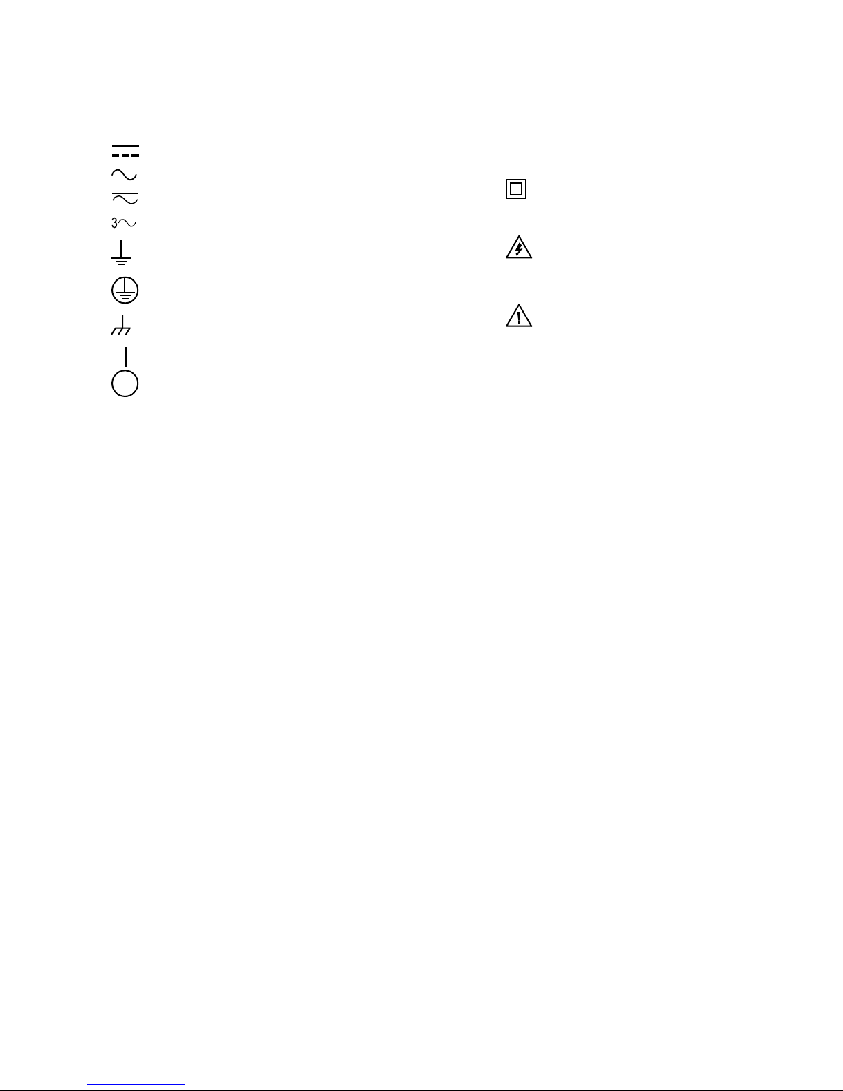
SAFETY SYMBOLS
Direct current (power line).
Alternating current (power line).
Alternating or direct current (power line).
Three-phase alternating current (power line).
Earth (ground) terminal.
Lake Shore Model 620/622/623/647 Magnet Power Supply User’s Manual
Equipment protected throughout by
double insulation or reinforced
insulation (equivalent to Class II of
IEC 536 - see annex H).
Caution: High voltages; danger of
electric shock. Background color:
Yellow; Symbol and outline: Black.
Protective conductor terminal.
Frame or chassis terminal.
On (supply)
Off (supply)
Caution or Warning - See
instrument documentation.
Background color: Yellow; Symbol
and outline: Black.
viii
Forward
Page 11

Lake Shore Model 620/622/623/647 Magnet Power Supply User’s Manual
CHAPTER 1
INTRODUCTION
1.0 GENERAL
This chapter covers Features (Paragraph 1.1), Specifications (Paragraph 1.2), and Operating Characteristics
(Paragraph 1.3).
1.1 FEATURES
• True, Four-Quadrant Bidirectional Power Flow: Operate current or voltage as a source or a sink in
either positive or negative polarities. Sink power returns to the AC line instead of dissipating through an
energy absorber.
• Low Noise, High Stability Current Regulation: Analog output control uses a precision shunt for current
stabilization to better than 50 PPM of full-scale current over an 8-hour period.
• ±50 A, ±5 V (Model 620), ±125 A, ±30 V (Model 622), ±155 A, ±30 V (Model 623),
or ±72 A, ±32 V (Model 647), Constant Current Output:
1. Programming resolution for Models 620/622/647 is 1.0 mA and 1 mV.
2. Programming resolution for the Model 623 is 1.2 mA and 1 mV.
• No current reversal switch required: Output current reversal is smooth and continuous with excellent
near zero current performance.
• Remote and local sensing of output voltage: Compensates for voltage drops in the output leads.
• Quiet switched-mode design: Results in a highly efficient, lightweight unit capable of air cooling.
• Front Panel Graphic Display: Allows continuous display of output while setting parameters from the
menu-driven keypad. Operating parameters that can be set and monitored are:
1. Output current and compliance setting.
2. Output current and voltage measurement.
3. Output current step limiting.
4. Output current zeroing.
5. Output ramp programming.
6. Status reporting.
7. Persistent switch heater control (with optional Model 6228 Card).
8. Liquid Helium level and Field monitoring (with optional Model 6226/6476 Card).
• Four methods of setting and monitoring all operating parameters:
1. From front panel.
2. From remote interfaces.
3. Through analog inputs and outputs.
4. Through optional Lake Shore MPS Driver Software.
• Automatic Mode: Easily controls Superconducting Magnets using the Model 6228 Persistent Switch
Heater Option Card.
• IEEE-488 Interface Option
• Model 6226/6476 Liquid Helium Level/Gaussmeter Input Option Card
• Model 6228 Persistent Switch Heater Option Card
• Protection: Overvoltage/Quench protection circuits which limit or turn off the MPS output, or turn off the
input in the event of an abnormal condition; current step limit exceeded; internal overtemperature; AC line
loss detection; remote inhibit; output power exceeded. Front panel annunciators, an audio alarm, and a
contact closure indicate faults.
Introduction
1-1
Page 12
Lake Shore Model 620/622/623/647 Magnet Power Supply User’s Manual
1.2 SPECIFICATIONS
Below are performance specifications for current with a 1 Henry load and voltage with a resistive load.
DC Output: True, Four-Quadrant, Bidirectional Power Flow output. Autoranging current and voltage operate
as a source or a sink in either polarity in current or voltage mode. Program current and compliance voltage via
the front panel, remote interfaces, or analog input. See Table 1-1 for DC Output Specifications.
Model 620 Model 622 Model 623: Model 647
Current: 0 to ±50 A Current: 0 to ±125 A Current: 0 to ±155 A Current: 0 to ±72 A
Voltage: 0 to ±5 V Voltage: 0 to ±30 V Voltage: 0 to ±30 V Voltage: 0 to ±32 V
Max Power: 250 VA contin. Max Power: 1 kVA contin. Max Power: 1 kVA contin. Max Power: 2 kVA contin.
Remote Sensing: Corrects for load lead drop of up to 0.5 V per lead. Operation with more drop per load lead
is possible with a degradation of the load effect specification.
Output Terminals: The two rear panel output bus bars are isolated from the chassis (earth) ground.
Multiple Unit Operation: Connect up to four units in an auto-parallel configuration for increased output
current capability.
Protection: Front panel annunciators, an audio indicator, and a contact closure indicate faults.
Remote Inhibit (RI): An active RI forces output settings to 0 A and 1 V until the RI is no longer active. To
continue normal operation, enter new output settings.
Output Inhibit (OI): Press the front panel OI key to force output settings to 0 A and 1 V. To continue normal
operation, enter new output settings.
Output Current Step Limit: The output current settings are forced to 0 A and 1 V if a preset current step limit
is exceeded. A key entry is required to continue operation.
Utility Low Line or Loss: Maintains operation until load is discharged or utility is restored.
Utility High Line: Turns off input and maintains operation until load is discharged.
Overvoltage: Crowbars output when output terminal voltage, induced by the load exceeds ±40 VDC.
Overtemperature: Crowbars output and turns off input when internal heat sink temperature exceeds 95 °C.
AC Input: Models 620/622/623 are factory set for operation from 100, 120, 200/208, 220, or 240 VAC
(–10%, +5%) 50 to 60 Hz single phase. Model 647 is factory set for operation from 200/208, 220, or 240 VAC
(–10%, +5%) 50 to 60 Hz single phase.
Input Protection: A front panel 20 A two-pole circuit breaker protects the AC input. The MPS turns off the
breaker in the event of a fault.
Remote Interfaces: Serial Interface is standard; IEEE-488 is optional. All front panel functions can be
controlled over the interfaces. In addition, interfaces output displayed quantities.
Input Current:
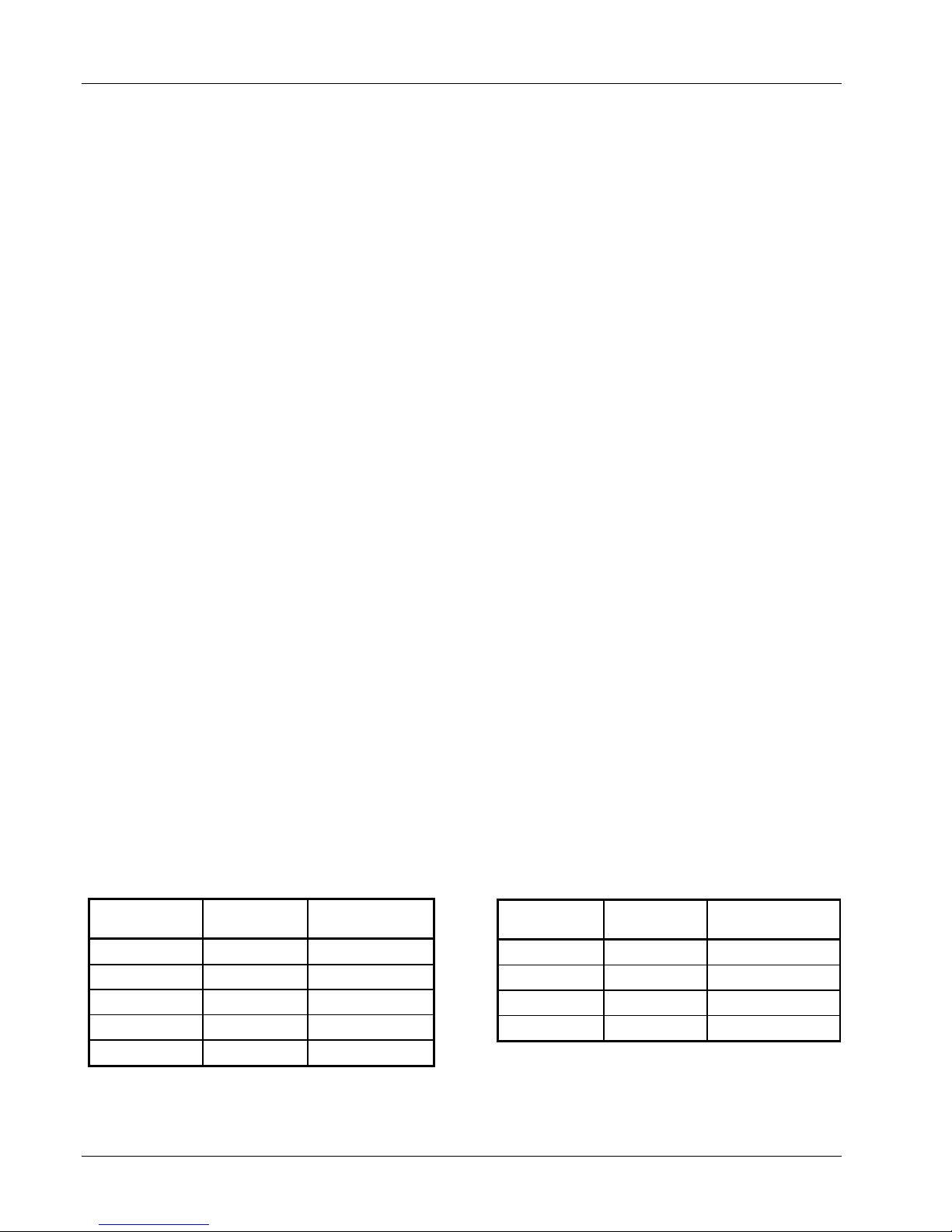
Table 1-1. Model 620/622/623 Input Current
Nominal Line
Voltage (VAC)
Line Voltage
Range (VAC)
Maximum Input
Current (A rms)
100 90 to 105 18
120 108 to 126 15
200/208 180 to 218 9
220 198 to 231 8
Table 1-2. Model 647 Input Current
Nominal Line
Voltage (VAC)
Line Voltage
Range (VAC)
200 180 to 210 16
208 188 to 218 15
220 198 to 231 14
240 216 to 250 13
Maximum Input
Current (A rms)
240 216 to 252 7
1-2
Introduction
Page 13
Lake Shore Model 620/622/623/647 Magnet Power Supply User’s Manual
Front Panel: Contains a menu driven keyboard and graphic display for entry and display of results. Operating
parameters to set and monitor from the front panel (and remote interface) include:
• Output current and compliance voltage setting.
• Output current and voltage measurement.
• Status reporting.
• Output ramp programming.
• Persistent switch heater control (with optional Model 6228 Card).
• Liquid helium level monitoring (with optional Model 6226/6476 Card).
• Field Monitoring (with optional Model 6226 Card).
• Output Current Zeroing.
• Output Current Step Limiting.
Magnet inductance and compliance (di/dt = V
/L) limit the output ramp programming charging current.
SET
Program output for a constant 0.01 to 99.99 amperes per second as long as compliance is not exceeded.
Energize or de-energize the magnet at a pre-set ramp rate. Pause the ramp at any time during the ramp.
During a pause, the MPS maintains output values until the ramp continues.
Operating Ambient Temperature: 15 to 35 °C (59 to 95 °F)
Dimensions: 483 mm wide x 178 mm high x 508 mm deep (19 x 7 x 20 inches)
Weight: 43.5 kilograms (96 pounds). Rack mounting is standard.
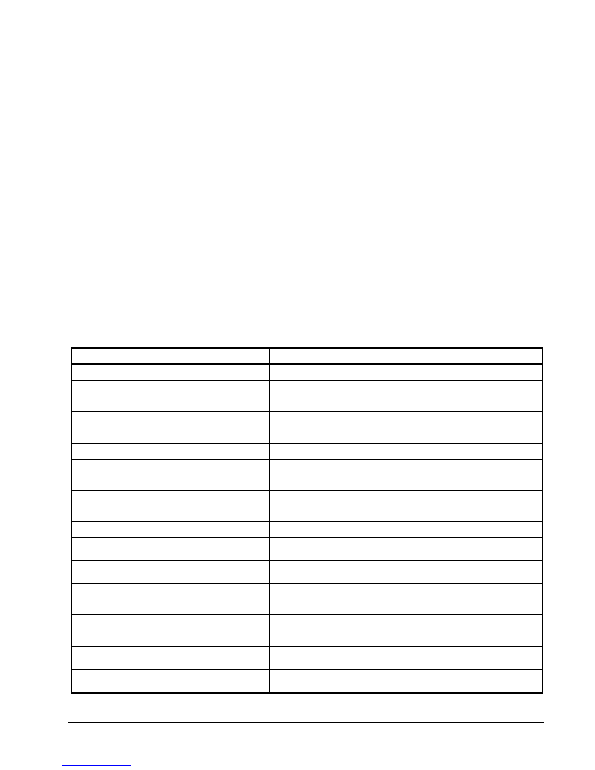
Table 1-3. Model 620/622/623 DC Output Specifications
SPECIFICATION CURRENT VOLTAGE
Digital Programming Resolution for 620/622
Digital Programming Resolution for 623
Digital Programming Accuracy
Digital Programming Repeatability
Electronic Resolution for 620/622
Electronic Resolution for 623
Electronic Accuracy
Display Resolution
Stability (Drift) at 25 ±1 °C: Percent of full scale
output change over 8-hours under constant line and load after
a 30 minute warm-up.
Ripple and Noise: 10 Hz to 10 MHz at 1000 VA
Temperature Coefficient: Change in output per °C
after 30 minute warm-up.
Source Effect: Line regulation for any line change within
the rated line voltage.
Load Effect: Load regulation for a load change equal to
maximum voltage in Constant Current Mode or maximum
current in Constant Voltage Mode.
Analog Resistance Programming Accuracy:
0 to 10 KΩ produces negative full scale to positive full scale
current or voltage output. 5 KΩ is 0 current.
Analog Voltage Programming Accuracy:
Voltage input is ±0.01 V/A, ±0.01 V/V.
Monitoring Output Accuracy: Voltage output is
±0.01 V/A, ±0.01 V/V.
1 mA 1 mV
1.2 mA 1 mV
0.1% I
0.01% I
MAX
MAX
1 mA 1 mV
1.2 mA 1 mV
0.1% I
MAX
1 mA 1 mV
±0.005% I
MAX
20 µA rms 10 mV rms
±0.01% I
±0.005% I
±0.01% I
10% I
1% + 100 mA
1% + 100 mA
MAX
MAX
MAX
MAX
±30 mV
±30 mV
±30 mV
±3 mV
±3 mV
±15 mV
±3 mV
3 V
2% + 100 mV
2% + 100 mV
Introduction
1-3
Page 14
Lake Shore Model 620/622/623/647 Magnet Power Supply User’s Manual
Table 1-4. Model 647 DC Output Specifications
SPECIFICATION CURRENT VOLTAGE
Digital Programming Resolution:
Standard/High
Digital Programming Accuracy
Digital Programming Repeatability
Electronic Resolution:
Standard/High
Electronic Accuracy
Display Resolution: Standard/High
Stability (Drift) at 25 ±1 °C: Percent of full scale
output change over 8-hours under constant line and load after
a 30 minute warm-up.
Ripple and Noise: 10 Hz to 10 MHz at 1000 VA
Temperature Coefficient: Change in output per °C
after 30 minute warm-up.
Source Effect: Line regulation for any line change within
the rated line voltage.
Load Effect: Load regulation for a load change equal to
maximum voltage in Constant Current Mode or maximum
current in Constant Voltage Mode.
Analog Resistance Programming Accuracy:
0 to 10 KΩ produces negative full scale to positive full scale
current or voltage output. 5 KΩ is 0 current.
Analog Voltage Programming Accuracy:
Voltage input is ±0.01 V/A, ±0.01 V/V.
Monitoring Output Accuracy: Voltage output is
±0.01 V/A, ±0.01 V/V.
10 mA / 1 mA 10 mV / 1 mV
0.1% I
0.01% I
MAX
MAX
1% V
0.1% V
MAX
MAX
4 mA / 1 mA 1 mV / 1 mV
0.1% I
10 mA / 1 mA 10 mV / 1 mV
±0.005% I
MAX
MAX
0.1% V
±0.01% V
MAX
MAX
40 µA rms 20 mV rms
0.1% I
0.005% I
0.1% I
10% I
MAX
MAX
MAX
MAX
1% + 100 mA
1% + 100 mA
0.1% V
0.05% V
0.1% V
10% V
MAX
MAX
MAX
MAX
2% + 100 mV
2% + 100 mV
1.3 OPERATING CHARACTERISTICS
Many Lake Shore MPS operating characteristics ideally suit it for charge and discharge cycling of
superconducting magnet loads. These characteristics significantly differentiate a Lake Shore MPS from a
conventional MPS. Consider them when choosing the best MPS for a particular application.
1.3.1 True, Four-Quadrant Bi-directional Power Flow
Lake Shore MPS: Sets either positive or negative
current and voltage values. This true, four-
+V-VOutput
Voltage
quadrant operation significantly simplifies test
procedures and system design by eliminating
external switching or operator intervention to
reverse current polarity. The smooth, continuous
transition through zero current allows users to
analyze samples at very small current increments
-I
Energy flows
from magnet to AC line
Energy flows
from AC line to magnet
(as small as 1 mA) about zero. Power flow is bidirectional. Sink power (energy stored in the
magnet) returns to the AC line instead of
Output
Current
Energy flows from AC
line to magnet
Energy flows from magnet
to AC line
dissipating in an energy absorber. The MPS either
transfers power from the AC line to the magnet, or
from the magnet back to the AC line. The MPS
also tolerates AC line faults; in the event of utility
power failure, it draws power from the charged
load to maintain operation until utility restoration.
Output
Voltage
Figure 1-1. Four-Quadrant Power
1-4
Introduction
+I
Ouput
Current
Page 15
Lake Shore Model 620/622/623/647 Magnet Power Supply User’s Manual
Conventional MPS: Consists of a unipolar power supply with an energy absorber to dissipate magnet energy
during discharge. The energy absorber prevents reverse voltage generated during the discharge from
damaging the unipolar supply output. Other conventional supplies dissipate magnet energy in the power
supply output transistor pass-bank. This two-quadrant performance requires the output stage to absorb
considerable power during the discharge. In addition, uniform charge and discharge rates are not always
ensured.
Current reversal requires external current reversal switches or manual lead reversal. These units provide
pseudo-four-quadrant operation which introduces discontinuities at the current reversal point produced by
switching the leads. Current reversal switches may incorporate direction detection diodes which reduce
available magnet charging voltage and dissipate additional power. Current reversal switches must also
interlock to prevent lead reversal when current is present. Current reversal switches complicate high power
cabling requirements, increase chances of introducing output current instabilities, and require time to reverse
leads. Manual lead reversal introduces discontinuity at the current reversal point. A discontinuous transition
through zero current may require a small external supply for near zero current analysis. Utility power failure in
a conventional supply generally results in a magnet quench.
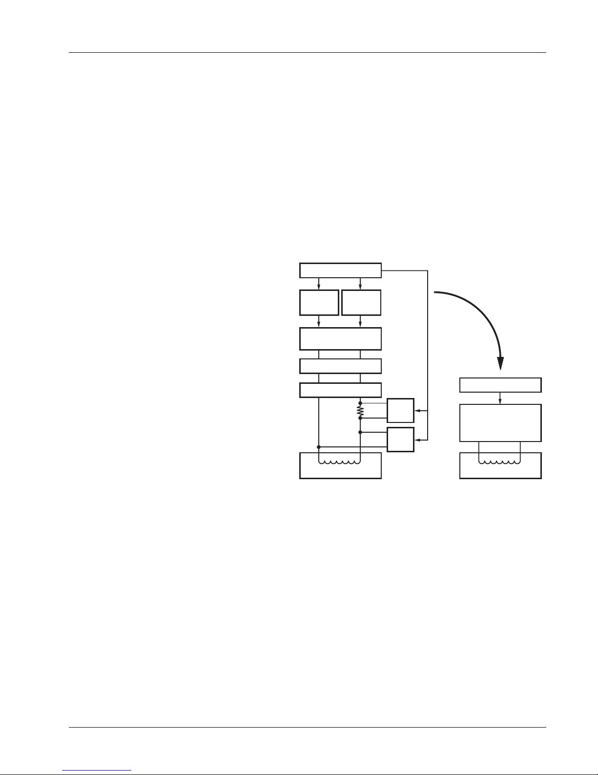
1.3.2 Low Noise, High Stability Current Regulated Output
Lake Shore MPS: Maintains a high-stability,
low-noise, current-regulated output. Digital
Computer
setting and monitoring electronics, and
computer interfacing integrate into power
management and precision analog control
circuitry. This integration maintains high output
stability and repeatability. Extensive output
filtering and noise cancellation circuitry keep
MPS output noise very low. The MPS front
panel graphic display allows continuous display
of output current and voltage while setting
parameters from the menu-driven keypad. In
addition to the front panel and remote interface
programming, the MPS includes analog inputs
and outputs for setting and monitoring operating
parameters. The MPS requires only 7 inches of
rack space.
Analog
Current
Programmer
Analog Programmed
Power Supply
Current Reversal
Energy Absorber
Analog
Voltage
Programmer
DVM
Current
Monitor
DVM
Voltage
Monitor
Now
Replaced
by:
Computer
Lake Shore MPS
True, Four-Quadrant
Bi-Directional
Power Flow
Conventional MPS: Some use a compliance
limited output with current monitoring to charge
the magnet. Others require output current to
Magnet Load
Magnet Load
drive against the output current limit to prevent
output current drift. Most use multi-turn
Figure 1-2. Comparison of Old and New MPS Designs
potentiometers and digital (or analog) panel
meters for front panel current and compliance
voltage setting. The elegance and repeatability of keypad entry is not available. There is no digital setting or
monitoring integration in the output control circuitry. Most achieve computer interfacing by adding computer
controlled voltage sources to analog program the output current and voltage. Additional inputs must be
added to digitize the output current and voltage. Setting and monitoring resolution is one to two orders of
magnitude poorer than the standard MPS provides. External setting and monitoring complicates cabling.
Degradation of the output current stability due to the addition of external cabling is undefined. Output noise
specifications are rarely given and sometimes vary with the type of magnet load driven. These multiple unit
configurations require up to 36 inches of rack space.
Introduction
1-5
Page 16

Lake Shore Model 620/622/623/647 Magnet Power Supply User’s Manual
1.3.3 Highly Efficient, Air Cooled, Compact Unit
Lake Shore MPS: Quiet switched-mode design. The output uses a proprietary pulse width modulated
technique that incorporates power hybrid circuitry. Extremely low conduction loss components minimize
internal power dissipation. The MPS is not a direct off-line switching supply. The output is fully floating and
isolated from ground. Active power factor correction draws a sinusoidal AC current waveform from the utility,
minimizes AC line harmonics, and lowers AC current required. Power factor is the ratio of real power
(measured in watts) to the apparent power (measured in volt-amperes). The combination of quiet switchedmode design and active power factor correction results in a compact, highly efficient, air-cooled unit.
Conventional MPS: Most use linear regulated outputs. The output transistor pass-bank internally dissipates
power not delivered to the magnet. Some units use an off-line switching supply to provide the bulk power and
add output regulation. There is no input power factor correction. Low overall efficiency means higher input
power and current. Without power factor correction, a non-sinusoidal current with high peaks places
tremendous stress on fuses, circuit breakers, outlets, and wiring. Dedicated lines may be required because of
potential interaction with other equipment. These factors result in low overall efficiency, large size, and
considerable weight.
1-6
Introduction
Page 17

Lake Shore Model 620/622/623/647 Magnet Power Supply User’s Manual
CHAPTER 2
INITIAL SETUP AND CONNECTIONS
2.1 INSPECTING AND UNPACKING
The MPS ships in a special cardboard box with integrated forklift skid openings. Do not stack anything on top
of the MPS box. Upon receipt, set the box on a level surface with the pallet side down. Inspect the shipping
container for external damage. Make all claims for damage (apparent or concealed) or partial loss of shipment
in writing to Lake Shore within five (5) days from receipt of goods. If damage or loss is apparent, notify the
shipping agent immediately.
Cut off the plastic strapping and lift off the lid. Locate the MPS packing list and use it to check for receipt of all
components, cables, accessories, and manuals. Inspect each item for damage. Use two people to lift the
MPS. Retain internal packing material and box for reshipment. Fill out and send the warranty card.
If there is freight damage to any instruments, promptly file proper claims with the carrier and insurance
company and notify Lake Shore Cryotronics. Notify Lake Shore of any missing parts immediately. Lake Shore
cannot be responsible for any missing parts unless notified within 60 days of shipment. See the standard Lake
Shore Cryotronics, Inc. Warranty on the A Page (immediately behind the title page).
2.2 MPS MOUNTING
After unpacking the MPS and verifying receipt of all packing list items, mount the instrument in a suitable
location. The MPS ships with feet installed and is ready for use as a bench top instrument. The MPS also
ships with 19-inch rack mounting hardware installed for mounting in a standard 19-inch rack enclosure.
CAUTION: To install the MPS in a 19-inch rack mount enclosure at any position other than the bottom,
install a slide rail or runner to support the MPS.
2.3 ENVIRONMENTAL REQUIREMENTS
Operate the MPS in an area with an ambient temperature range of 20 to 30 °C (68 to 86 °F). The unit may be
operated within the range of 15 to 35 °C (59 to 95 °F) with reduced accuracy.
The MPS is intended for laboratory use: no specific humidity or altitude specifications have been determined.
However, relative humidity of 20 to 80 percent (no condensation) and altitudes from sea level to 2.4 km
(8,000 feet) are generally acceptable.
WARNING: To prevent electrical fire or shock hazards, do not expose this instrument to moisture.
Provide adequate ventilation. The fan-cooled MPS draws air in from the sides and exhausts it from the rear;
install it with sufficient space at the rear and sides for air flow. Filter dust and other particulate matter at the
site to a reasonable level. For salt air, corrosive gases, or other air pollutants, consult an air-conditioning
expert for special filtering arrangements.
2.4 CONNECTING THE MPS TO POWER
Read and thoroughly understand sections 2.4.1 through 2.4.3 and the safety recommendations in the
Foreword before connecting the MPS to power. Failure to do so may expose operating personnel to lethal
voltages or damage the magnet and/or MPS.
Setup & Connections
2-1
Page 18

Lake Shore Model 620/622/623/647 Magnet Power Supply User’s Manual
2.4.1 Power and Ground Requirements
The AC power source for the MPS should be frequency and voltage regulated and isolated from sources that
may generate Electromagnetic Interference (EMI). The MPS is designed for single-phase 3-wire alternating
current (AC) power; do not use two-wire (without ground) AC power. Lake Shore recommends Ground Fault
Interrupter (GFI) and Transient Surge Protection circuitry at the AC source.
In areas where AC voltage varies, consider using a constant voltage transformer. For power outages, consider
using an Uninterruptible Power Supply (UPS).
CAUTION: Do not attempt to apply electrical power until the MPS is checked for proper line voltage
settings.
Factory-preset MPS line voltage requirements allow proper operation at the shipping destination. The line
voltage setting is indicated on the rear panel. Before applying power to the main input power cable, check for
correct input power settings for the power source voltage.
Ground the instrument panels and cabinets. The safety ground provides a true ground path for electrical
circuitry and, in the event of internal electrical faults such as shorts, carries the entire fault current to ground to
protect users from electrical shock. The MPS has a three-conductor power input connector which grounds the
MPS chassis when plugged into a 3-wire receptacle.
EMI is both a natural and man-made electromagnetic phenomena which, either directly or indirectly, may
degrade electronic system performance. Natural EMI includes thunderstorms, solar disturbances, cosmic
rays, etc. Man-made EMI includes fixed and mobile transmitters, high voltage power lines, power tools and
appliances, florescent lights, and other equipment containing motors, heaters, etc. Protect the AC source from
EMI. Consider transient surge protectors for lightning protection.
2.4.2 MPS Input Power Ratings
Operate the Model 620/622/623 from a nominal 100, 120, 200/208, 220, or 240 VAC (–10%, +5%)
single-phase AC power source, 50 to 60 Hz. Table 1-1 lists input voltage range and maximum current required
for each nominal input.
Operate the Model 647 from a nominal 200/208, 220, or 240 VAC (–10%, +5%) single-phase AC power
source, 50 to 60 Hz. Table 1-2 lists input voltage range and maximum current required for each nominal input.
A rear panel label indicates MPS factory-preset nominal line voltage. Normally, the line voltage setting is not
changed in the field. Consult the factory to reconfigure the input power.
2.4.3 Input Power Connections
The MPS uses a three-prong detachable input power connector (supplied) to mate with the UL/CSA/IEC
approved rear panel AC input connector. The user supplies a three conductor power cord rated for at least 85
°C operation. For 100 or 120 VAC operation, each conductor must be AWG #14 or larger. For 200/208, 220 or
240 VAC operation, each conductor must be AWG #16 or larger. Larger wires may be required to prevent
excessive voltage drop in the AC power lines if the unit is located an extended distance from the main AC
distribution terminals.
WARNING: For proper circuit breaker protection, mate the wire connected to the “L” terminal of the
connector to the “L” (hot) side of the line and mate the wire connected to the “N” terminal to the “N”
(neutral) side of the line. Mate the wire connected to the “GND” terminal to earth ground. Do not
operate this instrument without an adequate ground connection.
CAUTION: Before applying power to the MPS, verify that the AC source matches the line voltage listed
on the rear panel.
NOTE: Make connections to the AC power line in accordance with applicable electrical codes. The
international color code for identifying utility supply conductors is green/yellow for earth (“GND”), blue for
neutral (N), and brown for line (L). The US and Canadian codes are green for earth (“GND”), white for neutral
(N), and black for line (L).
2-2
Setup & Connections
Page 19
Lake Shore Model 620/622/623/647 Magnet Power Supply User’s Manual
Use this procedure to connect input power to the MPS:
1. Loosen the two connector cover screws and open the cover.
2. Slip the strain relief over the power cable with the flanged end at the end to be terminated.
3. Attach the wires to the connector in accordance with prevailing color codes: green or green/yellow to the
“GND” terminal, white or blue to the “N” terminal, and black or brown to the “L” terminal.
4. Position the strain relief, close the cover, and then tighten the cover screws.
5. Connect the other end of the power cord to an appropriate AC power source.
6. Plug the power cord into the detachable power connector plug on the MPS rear panel.
2.5 POWER UP
Read and follow instructions in Paragraphs 2.1 thru 2.4.3 and safety recommendations in the Foreword before
applying power to the MPS. Do not connect the MPS to the magnet at this point. Short the output terminals
together with a #4 gauge or larger cable. This protects the magnet against incorrect configurations.
Turn on the MPS. It requires approximately 2 seconds for initialization. Initially, all front panel annunciators
come on and the alarm sounds for a short time. Within 1 second, the Fault and Persistent Switch Heater On
annunciators and the alarm turn off. If the MPS detects a high or low AC line fault, it blinks the front panel
Fault annunciator and turns off the input circuit breaker. If this occurs, verify that the AC source matches the
line voltage listed on the MPS rear panel. The MPS front panel AC On LED lights any time the MPS is
connected to the AC line and the MPS power switch is ON.
Initially, the entire display clears and the alarm sounds for a short time. The MPS initializes itself and displays
the model identification. The Normal Display screen appears with a blinking asterisk indicating each update
when the unit is in normal operation.
2.5.1 Magnet Cable Connections
WARNING: Turn off the AC power before changing any rear panel connections and verify that all
connections are securely tightened before reapplying power.
CAUTION: Initially, setup the MPS without connecting it to the magnet. This lessens the chance for
inadvertent damage to the load while the user learns MPS operation.
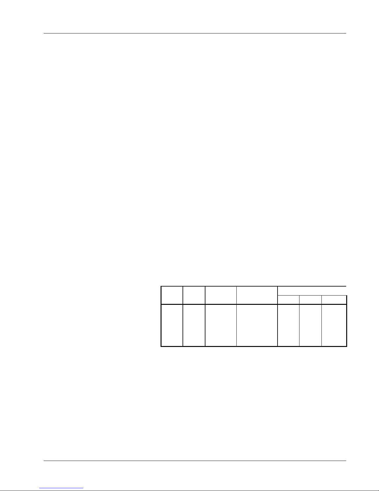
Make MPS load connections at the
+OUT and –OUT terminals on the rear
panel. These plated copper bus bars
accommodate 1/4 inch mounting
hardware. Use load wires heavy enough
to limit the voltage drop to less than 0.5
volts per lead. This ensures proper
regulation and prevents overheating
while carrying the output current. Use
remote sensing to compensate for any
voltage drop in the load leads and
Table 2-1. Load Wire Lengths and Current Capacity
Area Capacity Resistivity Total Lead Length (feet)
AWG (mm2) Amperes
0
2
4
6
8
53.5
33.6
21.2
13.3
8.4
245
180
135
100
75
ΩΩΩΩ/1000 feet
0.09827
0.1563
0.2485
0.3951
0.6282
75 A 100 A 125 A
135
85
53
33
21
101
64
40
25
—
81
51
32
—
—
obtain a more accurate voltage reading.
Stranded AWG #4 wire is capable of carrying in excess of 125 amperes. Keep conductor temperature under
85 °C for a 35 °C ambient. Table 2-1 lists the ampere capacity and total +OUT and –OUT lead lengths for load
connections.
If connecting multiple loads to the unit, use separate pairs of wires to connect each load to the output
terminals. Cut each pair of connecting wires as short as possible.
Setup & Connections
2-3
Page 20
Lake Shore Model 620/622/623/647 Magnet Power Supply User’s Manual
2.5.2 Shielding, Grounding, and Noise
For noise reduction, tightly twist and shield the leads from the MPS to the magnet. Connect the shield to the
MPS chassis as shown in Figure 2-3.
WARNING: DO NOT place magnet leads in contact with other MPS/system connections or metal parts.
In some instances, the user's measurement leads may pick up noise from the magnet leads. Although this
common mode noise may affect the user's measurement it rarely affects the current in the magnet. If the
user's measurement is earth grounded, some improvement is almost always possible by tying the –OUT
terminal of the MPS to earth ground – either at the MPS chassis or, if the user's system has one, the common
system earth ground point.
WARNING: If the –OUT terminal is tied to earth ground, make certain the +OUT cable from the MPS
contacts no other earth ground point - it forces the MPS output current into this other ground point. If
the other ground point is a small wire, it may melt or catch fire.
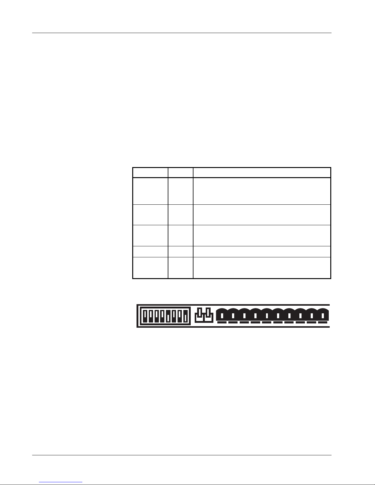
2.5.3 MPS Remote Inhibit and Fault Indicator Connections
The MPS has a Fault Indicator
(FLT) output and a discrete
Remote Inhibit (RI) input which
are both interface independent
and provide fault indication and
remote output shutdown in the
event of catastrophic failure.
The Fault Indicator relay contact
is open when the MPS detects
no faults. When the MPS
detects an internal fault, a
remote inhibit, or an output
inhibit, it lights the front panel
Fault LED and closes the relay
contact. The contact closure
alerts other system components
of the fault. In an auto-parallel
system (up to four MPS units
TERMINAL LABEL DEFINITION
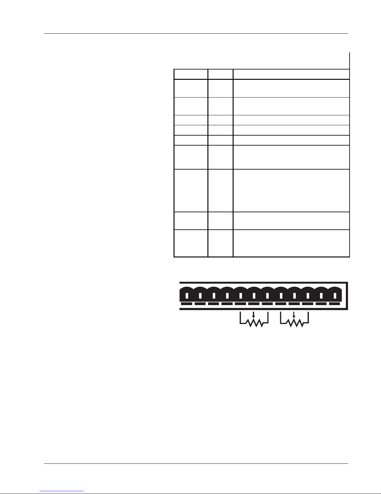
Table 2-1. RI, FLT, ON, and OVP Connections
1
2
3
4
5
6
RI+
RI–
FLT+
FLT–
ON+
ON–
7 NONE
8
OVP
Remote Inhibit – Active low, TTL-compatible input to
remotely force the output settings to 0 A and 1 V. Also
activate RI by shorting +RI to -RI with a relay contact closure
or a switch.
Fault Indicator – A relay contact that closes to indicate a
fault. Contact rating: 0.25 A resistive at 100 VDC, 3 W, 25
VA.
ON Indicator – A relay contact that closes to indicate when
the front panel circuit breaker is in the ON position. Contact
rating: 0.25 A resistive at 100 VDC, 3 W, 25 VA.
Factory Use Only. Do not connect to this terminal.
In auto-parallel MPS configurations, OVP ensures that the
activation of one MPS Over Voltage Protection circuit
activates all the other parallel MPS units' protection circuits.
connected in parallel) these
signals connect in parallel
between each of the MPS units
(See Paragraph 2.6 for details
MODE
INT
CAL AND ID V l
RI FLT ON
+- + - + - OVPImVm
12345678910
on connections between two
auto-parallel units). Make
connections to a rear panel
detachable terminal block
defined in Table 2-2 and Figure
2-1.
See Table 5-1B for
DIP Switch Definitions
Vl
EXT
Figure 2-1. RI, FLT, ON and OVP Connections
2.5.4 AC On Indicator
The MPS provides a discrete ON indicator. Terminals 5 and 6 on the terminal block connector, shown in
Figure 2-1 above, connect to relay contacts that close when the front panel circuit breaker is in the ON
position. There is also a front panel LED that lights when the MPS is ON and connected to AC power.
2.5.5 OVP Connection
In auto-parallel MPS configurations, this connection synchronizes the firing of the Over Voltage Protection
(OVP) circuits of each MPS (see Paragraph 4.7.4). See Paragraph 2.6 and Figure 2-4 for auto-parallel
connections.
2-4
Setup & Connections
Page 21
Lake Shore Model 620/622/623/647 Magnet Power Supply User’s Manual
2.5.6 MPS Analog Current And Voltage Monitoring Connections
The MPS provides amplified and buffered
current and voltage monitor output signals
Table 2-2. Analog Monitoring, Programming,
and Remote Sense Connections
at the terminal block on the back panel.
Connect these signals to external meters
TERMINAL LABEL DEFINITION
to indicate output current and voltage.
Obtain the Current Monitor signal through
9 Im
connections to terminals 9 (Im) and 11 (m)
with positive output currents producing a
positive monitor voltage of 10 mV/A from
Im to m.
Obtain the Voltage Monitor signal through
connections to terminals 10 (Vm) and
11 (m) with positive terminal voltages
10 Vm
11 m
12 Vp
13 +Vs
producing a positive monitor voltage of
10 mV/V from Vm to m.
14 –Is
2.5.7 External Current Programming
Remotely program MPS output current by
an external voltage or potentiometer.
15 Ip
Enable external analog programming via
the rear panel I MODE switch. When the I
MODE switch is in the INT I position,
external current mode is disabled. When
the I MODE switch is in the EXT I position,
16 +Is
the external programming voltage is
summed with the internal programming
voltage. Set the internal programming to
17
18
–S
+S
zero for external programming only. Apply
an external voltage from lp to m of 0 to
1.25 volts or use a 10 KΩ potentiometer to
control the output current over the entire
range. Make connections to rear panel
OVP Im Vm m Vp +Vs -ls lp +ls -S +S
7 8 9 101112131415161718
detachable terminal block defined in
Tables 2-3 and 2-4 and Figures 2-1 and 2-
2. The MPS produces 100 A of output
current for 1 V at the current programming
input.
Output Current Monitor – Voltage output
from Im to GND(M) is ±10 mV/A.
Output voltage monitor – Voltage output
from Vm to GND(M) is ±10 mV/V.
Monitor and program ground. GND(m).
Not Used.
Not Used.
Negative voltage supply for
programming external current with a
potentiometer
Current programming input voltage.
Voltage input from Ip to GND(m)
produces ±100 A/V. Voltage may come
from a voltage source or from the center
tap of a potentiometer connected from Is to +Is.
Positive voltage supply for programming
external current with a potentiometer.
Remote voltage sense correction.
Correction for load lead drops of up to
0.5 V per lead.
NOTE: MPS protection circuits reduce the
effect of open external programming leads.
An open external programming lead forces
external programming voltage to
approximately 0 volts.
2.5.8 Remote Sense Connections
The factory configures the MPS to sense, but not control remote voltage. Call Lake Shore to reconfigure the
MPS to control voltage at the load. When using remote sense, the MPS measures voltage at the magnet
instead of at the MPS output terminals allowing a more accurate reading of magnet voltage by eliminating
voltage drops in the leads connecting the MPS to the magnet. If using remote sense, the MPS bases the
voltage at the voltage monitor output on the remote sense voltage instead of the MPS terminal voltage.
Use AWG #24, shielded, twisted pair wiring for sense leads to minimize pickup of external noise. Any noise
on the sense leads may appear at the unit output. Ground sense shield to the MPS back panel.
Make Remote Sense Connections to the rear panel detachable terminal block defined in Table 2-3 and
Figure 2-2.
Setup & Connections
10K 10K
Figure 2-2. Analog Monitoring , Programming,
and Remote Sense Connections
2-5
Page 22
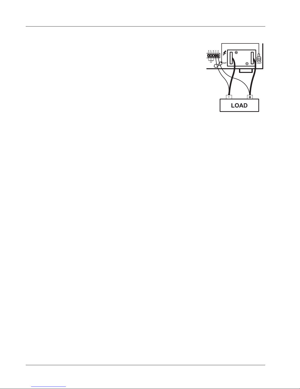
Lake Shore Model 620/622/623/647 Magnet Power Supply User’s Manual
NOTE: The MPS includes a protection circuit which reduces the effect of open
sense leads during remote voltage sensing operation. If the +S lead opens, the
MPS Rear View
output voltage changes because it is sensed between +OUT and the negative
side of the load. If the –S lead opens, the output voltage changes because it is
sensed between the positive side of the load and –OUT. If both leads open, the
output voltage is sensed internally.
The procedure below configures the MPS for remote voltage sensing as shown
in Figure 2-3.
1. Turn off the unit.
2. If present, disconnect any wires between the +OUT and –OUT terminals
and the +S and –S connections on the MPS rear panel.
Maintain
polarity!
Connect -S
to -OUT and
+S to +OUT.
3. Connect the sense leads from the MPS +S and –S connections to the load.
Maintain polarity when making these connections.
CAUTION: Maintain polarity between +S and +OUT and –S and –OUT. The
+S and –S inputs control the output voltage. Improper polarity may apply
Figure 2-3. Remote
Sensing Connections
damaging voltages to the load.
4. Connect the ground shield to the mounting screw. Make sure that the shield does not come into electrical
contact with either magnet lead.
2.6 MULTIPLE AUTO-PARALLEL SETUP
Connect up to four MPS units in an auto-parallel configuration for increased output current capability. The
maximum total current allowed is the sum of the maximum currents of the individual units. For example four
623 MPS units provide 4 × 155 = 620 amps total current. The maximum total power is the sum of the
maximum power ratings of the individual units.
Assign each unit a unique address: 1 for MPS 1, 2 for MPS 2, etc. The MPS at address 1 polls the control bus
to determine if an auto-parallel configuration is present and how many MPS units are involved. When multiple
MPS units are present, MPS 1 sends the output current and voltage limits, ramp status, output current step
limit, and other operating parameters to the other MPS units so all units operate identically.
For two MPS configuration, each MPS is programmed for half of the total output current. This is true for the
ramp destination current and ramp rate. Each MPS contributes half the output current required. MPS 1
software polls MPS 2 to determine the total output current. The output voltage, current settings during a ramp,
and instrument status from MPS 1 are reported (since the values are the same for both units.)
NOTE: When multiple MPS units are present, install the Model 6228 persistent switch heater output option in
MPS 1 for proper operation.
An analog signal is also provided for remote activation of the output over voltage protection (OVP) circuit. The
signals connect in parallel so that the output OVP circuits of each MPS activate in unison.
CAUTION: Consult Lake Shore prior to operating multiple MPS units in auto-parallel mode.
Use the procedure below and see Figure 2-4 to connect multiple MPS units in auto-parallel configuration:
1. Turn off all units and completely disconnect power at the source before changing MPS configuration.
2. Determine which MPS to assign as MPS 1 and configure it as follows:
a. Locate the CAL AND ID DIP switches on the rear panel. Turn ON (up position) switches 1 and 4. Turn
OFF (down position) switches 2, 3, and 5 through 8. (Switch 4 ON designates multiple MPS operation.
Switches 3, 2, and 1 respectively OFF, OFF, and ON assign the MPS address as 1). Note that the
CAL AND ID switch numbers are upside down (as viewed from the rear panel). Switch 1 is on the right
and switch 8 is on the left. Take care to use the correct switch numbers.
b. Move the I MODE switch to the INTernal (up) position.
2-6
Setup & Connections
Page 23

Lake Shore Model 620/622/623/647 Magnet Power Supply User’s Manual
c. Locate Communications Microprocessor (CMP) in the MPS rear panel. The CMP is the module with
two RJ-11 telephone jacks. Loosen two screws securing CMP to MPS rear panel and slide CMP out.
Just inside the CMP front panel, there is a set of DIP switches. Verify that switches 5, 6, and 7 are ON
(closed) and switches 1 through 4 and 8 are OFF (OPEN). (Switches 1–4 define the control bus as
Serial (RS-232C). Switches 5–8 define the control bus as RS-485 multidrop. Switch 8 terminates the
bus for long communications loop runs. Close switch 8 to terminate the control bus only if the MPS
units are a significant distance from each other.) Replace the CMP.
3. Configure the second MPS as MPS 2:
a. Locate the CAL AND ID switches on the rear panel. Turn ON (up position) switches 2 and 4. Turn
OFF (down position) switches 1, 3, and 5 through 8. (Switch 4 ON designates Multiple MPS operation.
Switches 3, 2 and 1 as OFF, ON, OFF, respectively, assign the MPS address as 2.)
b. Move the I MODE switch to the INTernal (up) position.
c. On the CMP, verify that switches 5, 6 and 7 are ON (closed) and switches 1 through 4 and 8 are OFF
(OPEN). Replace the CMP.
4. Connect the control bus. Use Lake Shore Model 2001 Modular Cables (provided) to interconnect the two
MPS CMP units.
5. Connect the MPS 1 over voltage protection (OVP) pin 8 to MPS 2 pin 8.
6. Connect the RI and FLT signals. Connect the +RI (terminal 1) to the +FLT (terminal 3) on MPS 2. Connect
the –RI (terminal 2) to the –FLT (terminal 4) on MPS 2. Do the same on MPS 1. Connect the +RI/+FLT
connection of MPS 2 to the +RI/+FLT connection of MPS 1. Connect the –RI/–FLT connection of MPS 2 to
the –RI/–FLT connection of MPS 1. If an external contact closure will remotely inhibit operation, connect it
across the +RI and –RI terminals of MPS 1. The +FLT and –FLT contact closure of MPS 1 indicates a
fault.
7. Connect the +OUT terminal of MPS 1 to the +OUT terminal of MPS 2. Connect the –OUT terminal of MPS
1 to the –OUT terminal of MPS 2. Make these leads as short as possible to minimize output potential
differences between the two MPS units and large enough to handle the maximum MPS current. Connect
the output terminals to the load using leads large enough to handle the total output current of both MPS
units.
NOTE: For proper operation, turn on MPS 1 and then MPS 2 within 15 seconds of MPS 1.
8. Verify all connections as summarized in Table 2-4.
9. To add a third MPS or a fourth MPS in parallel, make the RI/FLT,
OVP, CMP and output connections in parallel with the
connections of MPS 1 and MPS 2. For MPS 3, set the CAL AND
ID switches on the rear panel as follows : switches 5 through 8
are OFF, switches 4, 3, 2 and 1 are ON, OFF, ON, ON
respectively. For MPS 4, set the rear panel CAL AND ID
switches as follows : switches 5 through 8 are OFF, switches 4,
3, 2 and 1 are ON, ON, OFF, OFF respectively. Configure the
CMP switches for MPS 3 and MPS 4 as those in MPS 1 and
Table 2-3. Two-MPS Autoparallel
Configuration Connections
MPS 1 MPS 2
Control Bus
8 (OVP)
1 (+RI), 3 (+FLT)
2 (–RI), 4 (–FLT)
+OUT
–OUT
MPS 2.
NOTE: For proper operation, turn on MPS 1 and then the remaining MPS units within 15 seconds.
Control Bus
8 (OVP)
1 (+RI), 3 (+FLT)
2 (–RI), 4 (–FLT)
+OUT
–OUT
Setup & Connections
2-7
Page 24
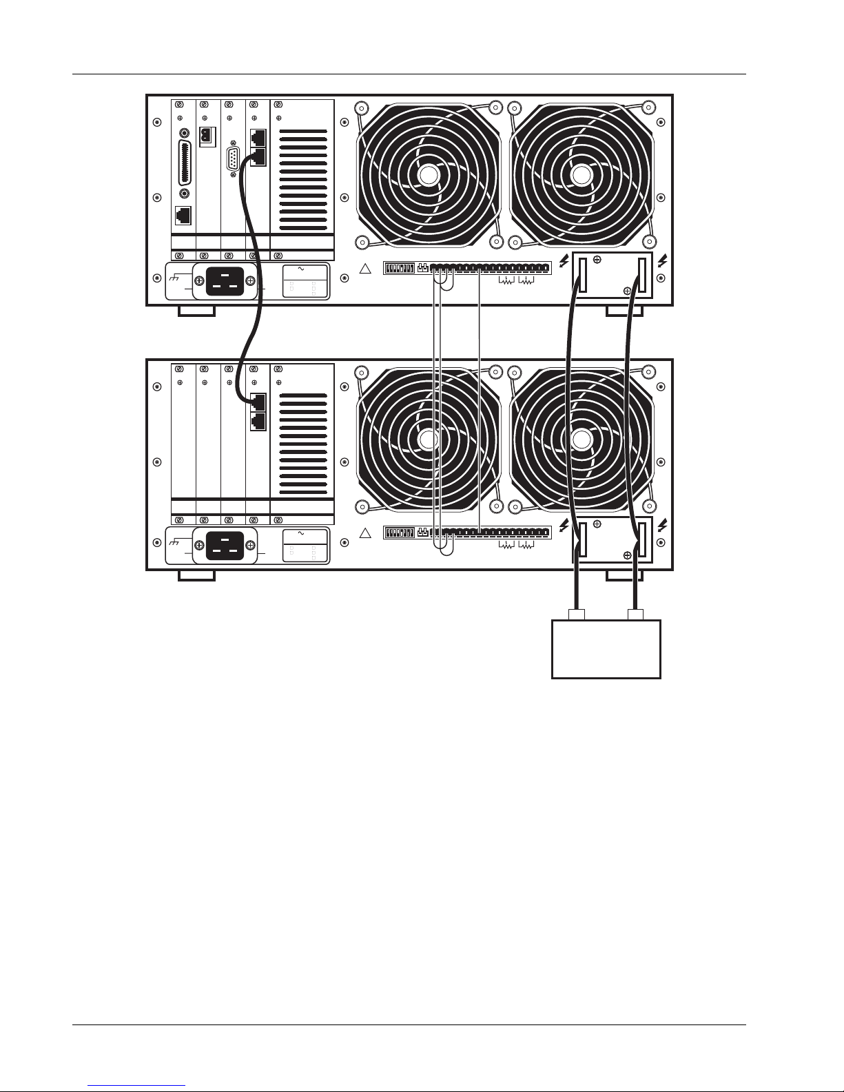
Lake Shore Model 620/622/623/647 Magnet Power Supply User’s Manual
RI FLT ON
MODE
INT
+ - + - + - OVPIm Vm mVp +Vs -ls lp +ls -S +S
LINE
-10% +5% 50-60 Hz
FIXED INTERNALLY
208
100
220
120
NL
NO USER SERVICEABLE PARTS INSIDE. REFER
SERVICING TO TRAINED SERVICE PERSONNEL.
240
CAL AND ID V l
!
WARNING:
1 2 3 4 5 6 7 8 9 101112131415161718
Vl
EXT
10K 10K
-OUT +OUT
MPS #1 Rear View
RI FLT ON
MODE
INT
+ - + - + - OVPIm Vm mVp +Vs -ls lp +ls -S +S
LINE
-10% +5% 50-60 Hz
FIXED INTERNALLY
208
100
220
120
NL
NO USER SERVICEABLE PARTS INSIDE. REFER
SERVICING TO TRAINED SERVICE PERSONNEL.
240
CAL AND ID V l
!
WARNING:
1 2 3 4 5 6 7 8 9 101112131415161718
Vl
EXT
10K 10K
-OUT +OUT
MPS #2 Rear View
-
+
LOAD
Figure 2-4. Typical Multiple MPS Connections for Two MPS Units
2.6.1 Multiple MPS Remote Inhibit Mode
In multiple MPS configuration, if the MPS RI indicators activate from an external contact closure, the MPS
units enter Multiple MPS Remote Inhibit Mode. They activate output overvoltage protection circuits and turn off
output circuits. If a charged load is present, OVP circuits discharge it. The front panel Fault annunciators turn
ON, and the internal audio indicators beep about once per second. If a MPS detects a fault, it initiates Multiple
MPS Remote Inhibit Mode by closing the FLT contacts. No delay is allowed (CAL AND ID switch 7 OFF, down
position) and multiple MPS operation (CAL AND ID switch 4 ON, up position) must be selected. After the load
discharges, turn OFF all units to reset.
2-8
Setup & Connections
Page 25

Lake Shore Model 620/622/623/647 Magnet Power Supply User’s Manual
2.7 POST-INSTALLATION INSTRUCTIONS
The MPS is electrically and mechanically inspected and operationally tested prior to shipment. It should be
damage-free and in perfect working order upon receipt. To confirm this, visually inspect the instrument for
damage and test it electrically to detect any concealed damage upon receipt. Study the entire MPS User’s
Manual before attempting to run the unit. See Chapter 3 for any questions on front panel control operation.
2.8 SYSTEM SHUTDOWN AND REPACKAGING FOR STORAGE OR SHIPMENT
Follow these general guidelines for system shutdown for storage or reshipment. If returning something, call
Lake Shore first to obtain a Return Goods Authorization (RGA) Number.
1. Turn off the power to all instruments. Unplug the power cord.
2. Remove or disconnect any interface cables and the magnet current output cables.
3. Repack the MPS upside down in the original box. If returning the MPS to Lake Shore and original box is
unavailable, please call Lake Shore for a replacement box.
4. Label the box for storage or shipment.
2.9 RETURNING EQUIPMENT TO LAKE SHORE
To return the MPS for repair or replacement, obtain a Return Goods Authorization (RGA) number from a
factory representative before returning the instrument to our service department. When returning an
instrument for service, Lake Shore requires the following information before attempting any repair:
1. Instrument model and serial number.
2. User's name, company, address, and phone number.
3. Malfunction symptoms.
4. Description of system.
5. Returned Goods Authorization number.
Consult the factory for shipping instructions. Ship the MPS upside down in the original shipping box.
Setup & Connections
2-9
Page 26

Lake Shore Model 620/622/623/647 Magnet Power Supply User’s Manual
This Page Intentionally Left Blank
2-10
Setup & Connections
Page 27
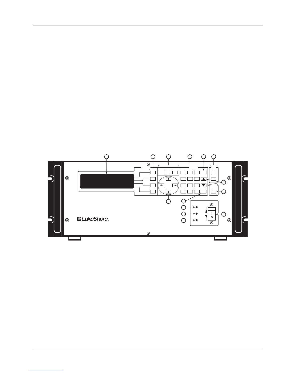
Lake Shore Model 620/622/623/647 Magnet Power Supply User’s Manual
CHAPTER 3
OPERATION
3.0 GENERAL
This chapter covers seven areas: MPS Front Panel (Paragraph 3.1), Power Up (Paragraph 3.2), Setting
Current on an MPS with Manual PSH Control (Paragraph 3.3), Setting Current with Automatic PSH Control
(Paragraph 3.4), Instrument Setup Screens (Paragraph 3.5), Function Menus (Paragraph 3.6), and an
Automatic Persistence Control Example (Paragraph 3.7).
Setup the MPS software with the MPS output terminals shorted together as in section 3.2. This ensures that
while the user learns MPS operation, an inadvertent keystroke causes no damage to the magnet.
3.1 THE MPS FRONT PANEL
Figure 3.1 below shows the MPS Front Panel. The up or down Display Cursor Control keys move the line
indicator to the line containing a value to be changed. Use either the Data Entry Keypad to enter the desired
value or the up or down Numeric Entry keys to increment or decrement the value. The Enter key accepts the
update, while the Esc key discards the change and returns to the prior value. Move the cursor to a particular
digit with the right and left Display Cursor Control keys and change it with the Numeric Entry keys.
A
Magnet Power Supply
Functions
B
Function
Menu
A. Display Screen
G. Data Entry Up and Down Keys. Increment and
B. Display Function Keys
C. Display Menu Selection Keys
D. Data Entry Keypad
E. Escape Key. Restores an old value and
returns from a Function Screen to
Normal Screen. Also Aborts a ramp or
automatic process.
F. Interface Keys
H. Output Inhibit Key
I. Display Cursor Control Keys
J. Enter Key. Accepts a change.
K. Power Indicator
L. Fault Indicator
M. Persistent Switch Heater Indicator
N. Power Switch
Figure 3-1 MPS Front Panel
Menu
Cursor
C
Normal
Next
Display
I
D
Data Entry
7 8 9
4 5 6
1 2 3
.
0
J
K
L
Switch Heater
M
Power
Persistent
E
F
Mode
Local
Esc
Remote
G
Output
Inhibit
Enter
+/-
ON
Fault
OFF
H
N
decrement numeric values, Pause/Restart
ramps, or execute some functions.
Operation
3-1
Page 28

Lake Shore Model 620/622/623/647 Magnet Power Supply User’s Manual
3.2 POWER UP
Read and follow instructions in Paragraphs 2.1 - 2.4.3 and the Forward safety recommendations before
applying power to the MPS. Do not connect the MPS to the magnet yet. Short the output terminals together
with a #4 gauge or larger cable to protect the magnet against incorrect configurations.
Turn on the MPS. It requires approximately 2 seconds for initialization. Initially, all front panel annunciators
come on and the alarm sounds for a short time. Within 1 second, the Fault and Persistent Switch Heater On
annunciators and the alarm turn off. If the MPS detects a high or low AC line fault, it blinks the front panel
Fault annunciator and turns off the input circuit breaker. If this occurs, verify that the AC source matches the
line voltage listed on the MPS rear panel.
Initially, the entire display clears and the alarm sounds for a short time. The MPS initializes itself and displays
the model identification. The Normal Display screen appears with a blinking asterisk indicating each update
when the unit is in normal operation.
Depending on the existence of the PSH Option Card and the mode of operation, the MPS displays one of
three possible Normal Displays on power up: one for Manual Mode (no PSH Option Card), one for Manual
PSH Control, or one for Automatic PSH Control. The factory-preset is the Normal Display for Manual Mode,
but the MPS remembers the last PSH mode selected at power down and powers up in that mode. Without an
PSH option installed, the MPS powers up in the Normal Display for Manual Mode.
Set Magnet Ramp Rate and Persistence Switch Ramp Rate in the Normal Display screen. Set Field Units,
Maximum Current, and Compliance Voltage in the Instrument Setup Screen. Set Current Step Limit in the
Step Limit/Zero screen.
CAUTION: Set magnet parameters according to manufacturer's specifications. Failure to do so may
damage the magnet and threaten user safety.
3.3 NORMAL DISPLAY FOR MANUAL MODE
Shown to the right is the default startup Normal
Display for Manual Mode. For operation with the
PSH card installed see Paragraph 3.4 for MANUAL
persistence mode or Paragraph 3.5 for
AUTOMATIC persistence mode.
SETTINGS:
¤
+ 0.1999A
COMPLIANCE
RAMP RATE
RAMP ENABLE
:§ 1.000V
:§ 1.000A/S
: <OFF> ¥
OUTPUTS: *
+1.999A
+0.001V
The Normal Display screen allows entry of MPS
output current (or field) settings at any time. Settings
cannot exceed limits in the INSTRUMENT SETUP screen. The OUTPUTS portion of the screen indicates
output values and computer interface status. The Normal Display key returns the display to this screen at any
time.
Use the Cursor keys to move the line indicator up or down. Parameters with a
¥ icon toggle with the Data
Entry up or down key. Change all others using any numeric entry mode, including the cursor.
CURRENT / FIELD:
MPS Output Setting. This line reads CURRENT if set to display amps and FIELD if set to display computed
field (see Paragraph 3.6.1.4). To set MPS output, move to the CURRENT / FIELD line and enter the new
setting. If RAMP ENABLE is ON, the current or computed field ramps to the new setting at the displayed
RAMP RATE. If RAMP ENABLE is OFF, the current or field changes to the new value immediately or to the
value that causes MPS voltage COMPLIANCE. However, it is not recommended to operate the MPS with
RAMP ENABLE OFF; it may cause a magnet quench (see Forward).
COMPLIANCE (Read only):
Compliance Setting. Change the COMPLIANCE voltage in the INSTRUMENT SETUP screen (See Paragraph
3.6.1.4).
RAMP RATE:
Ramp Rate Setting. Exceeding the maximum rated magnet voltage or current ramp rate may damage the
magnet. Users may configure the MPS to limit the voltage by adjusting the compliance. If RAMP ENABLE is
ON, RAMP RATE controls the rate at which the magnet current reaches the current setpoint as long as the
MPS does not go into compliance. (See Paragraph 3.6.1.4).
NOTE: To pause or restart a ramp, press either the Data Entry up or down key. To abort a ramp, press Esc.
3-2
Operation
Page 29

Lake Shore Model 620/622/623/647 Magnet Power Supply User’s Manual
The magnet manufacturer supplies the inductance of the magnet, maximum ramp voltage, and maximum
current ramp rate. The relationship for these parameters is given by the equation:
di
max
where: V
L
≥
dt
= rated maximum magnet ramp voltage in volts,
max
L = magnet inductance in henrys, and
di/dt = maximum magnet current ramp rate in amps/second.
To set the Magnet Ramp Rate for manual PSH control or no PSH control, move to the RAMP RATE line and
enter a ramp rate less than the magnet's maximum ramp rate. In manual PSH control, the MPS uses the
RAMP RATE value to ramp both the magnet current and the persistence switch current. To activate ramping,
move to the RAMP ENABLE line and toggle RAMP ON. Upon entering a new current set point, the current
ramps at the entered ramp rate.
RAMP ENABLE: <ON> or <OFF>
RAMP ENABLE ON causes current to ramp at the specified ramp rate when the current/field is changed. Turn
RAMP ENABLE OFF to force the MPS to step immediately to the new CURRENT (or FIELD) SETTING. Move
to the RAMP ENABLE line and toggle the RAMP ENABLE OFF.
3.4 NORMAL DISPLAY FOR MANUAL PSH CONTROL
To the right is the default start-up Normal Display
screen for an MPS with a PSH option card installed
and Manual Persistence Control Mode selected. To
change to Automatic Persistence Control Mode,
press the MENU key and select Automatic Mode
from Function Menu 1. For Automatic Persistence
Control Mode see Paragraph 3.5.
SETTINGS:
¤
+ 0.1999A
COMPLIANCE
RAMP RATE
RAMP ENABLE
PERSISTENCE
:§ 1.000V
:§ 1.000A/S
: <OFF> ¥
: <ON> ¥
OUTPUTS: *
+1.999A
+0.001V
The Normal Display for Manual PSH Control functions the same as the Normal Display for Manual Mode with
the exception of the option below:
PERSISTENCE: <ON> or <OFF>
Persistence Mode Status. If Persistence Mode is On, the PSH heater is Off. If it is Off, the PSH heater is On.
Note: To set PSH heater current, see Chapter 6 Options And Accessories.
3.5 NORMAL DISPLAY FOR AUTOMATIC PSH CONTROL
To the right is the default startup Normal Display
screen for an MPS with a PSH option card installed
and Automatic Persistence Control selected. To
change to Manual Persistence Control Mode press
the MENU key and select MANUAL MODE. For
Manual PSH Control Mode, see Paragraph 3.4.
AUTOMATIC MODE:
¤MGT START
MGT END
MGT RATE
PERS RATE
LAST END
PERSISTENCE
RUN ¥
: 0.000A
: 0.000A
: 1.000A/S
: 1.000A/S
: 0.000A
: <OFF>
OUTPUTS: *
+0.000A
+0.001V
STANDBY
When using a Persistence Switch, Automatic Mode
simplifies superconducting magnet control. After the user defines initial parameters, Automatic Mode permits
the MPS to use two different ramp rates and four time delays, and to manage the Persistence Switch Heater
to change magnet current from its existing value to a new value automatically. Dithering is supported (see
Paragraph 3.9).
Use the Cursor keys to move the line indicator up or down. Change parameters using any numeric entry
mode, including the cursor.
MGT START: 0 to ±50.000 A (620), 0 to ±125.000 A (622), 0 to ±155.000 A (623), 0 to ±72.000 A (647)
Magnet Start Current. The current in the magnet in persistence prior to the automatic run. The MPS opens the
persistence switch after it reaches this current and the user-specified delay expires.
Operation
3-3
Page 30

t
Lake Shore Model 620/622/623/647 Magnet Power Supply User’s Manual
MGT END: 0 to ±50.000 A (620), 0 to ±125.000 A (622), 0 to ±155.000 A (623), 0 to ±72.000 A (647)
Magnet End Current. The desired magnet current. To set a new current, move to the MGT END line and enter
a new current, then move to the RUN line and toggle to activate Automatic Mode. The MPS automatically
ramps to the new current, returns the magnet to persistence, then ramps MPS current back down to zero.
MGT RATE: 0 to ±99.999 A/sec
Magnet Ramp Rate. Rate in amperes per second that the MPS charges the magnet. Exceeding the maximum
rated voltage or current ramp rate may damage the magnet. The user may configure the MPS to limit the
charging voltage.
The magnet manufacturer supplies the inductance of the magnet, maximum ramp voltage, and maximum
current ramp rate. The relationship for these parameters is given by the equation:
di
L
V<
max
d
where: L = magnet inductance in henrys,
di/dt = maximum magnet current ramp rate in amps/second,
V
= rated maximum magnet ramp voltage in volts.
max
To set the Magnet Ramp Rate for automatic PSH control, move to the MGT RATE line and enter a ramp rate
less than the magnet's maximum ramp rate. Upon entering a new current set point, the magnet current ramps
at the entered magnet ramp rate.
PERS RATE: 0 to ±99.999 A/sec
Persistence Switch Ramp Rate. Rate in amperes per second of the MPS when in Persistence Mode. The
current is flowing in the Persistent Switch and the rate is chosen as such. To set the Persistence Switch Ramp
Rate, move to the PERS RATE line and enter a persistence switch ramp rate less than the maximum allowed.
This value is usually considerably higher than the magnet ramp rate as there is little inductance in the
persistence switch.
LAST END:
The ending charge current from the last time the MPS charged the magnet. The MPS sets this field after it
charges the magnet to the Magnet End value. Once it reaches Magnet End, the MPS sets the value of Last
End equal to the value of Magnet End. The user cannot change the Last End value. The MPS stores it in nonvolatile memory and remembers it even when the MPS is Off.
PERSISTENCE: <ON> or <OFF> (Read only)
Persistence Mode Status. If Persistence Mode is On, the PSH heater is Off. If it is Off, the PSH heater is On.
The persistent switch takes the superconducting magnet into and out of persistence mode.
To exit persistent mode, the MPS current ramps up to match the persistent current, and the persistent switch
heater coil heats the switch until it becomes normal (non-superconducting). A delay allows magnet current to
settle. Then the magnet current ramps to a new value.
To enter persistent mode, the MPS removes current from the persistent switch heater. After a delay to allow
the switch to superconduct, the MPS current ramps down to 0 at a rate low enough to ensure the switch
remains superconducting. The magnet current then circulates in the superconducting loop formed by the
magnet and the persistent switch.
Note: To set PSH current see Chapter 6 Options And Accessories.
RUN
¥¥¥¥:
Press either of the Data Entry up or down key to initiate Automatic Mode.
3-4
Operation
Page 31
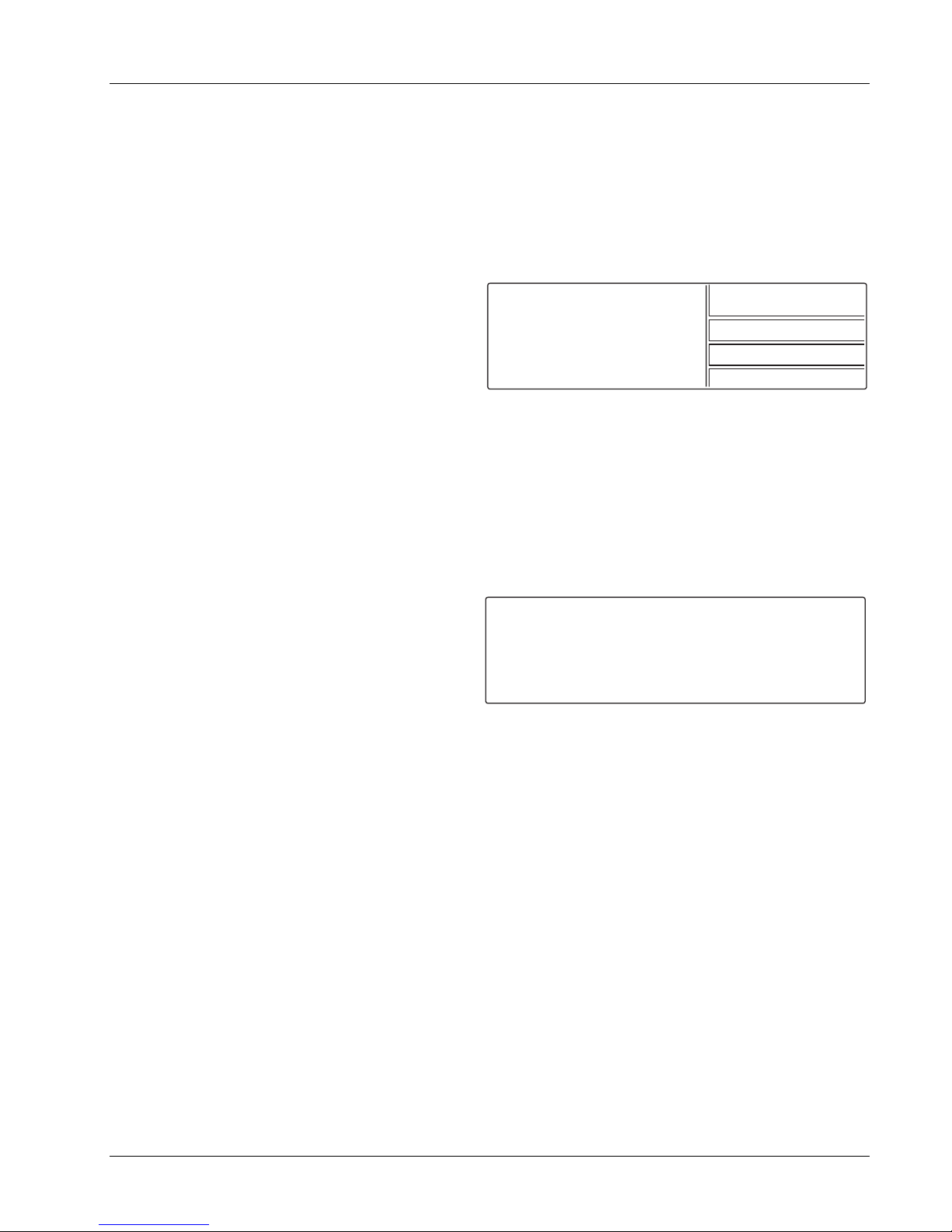
Lake Shore Model 620/622/623/647 Magnet Power Supply User’s Manual
3.6 FUNCTION MENUS
The MPS uses a system of three Function Menus for setup. Function Menus 1 and 2 do not require a PSH
Option Card, but the presence of one changes the look of the menus. The Function Menu 3 requires a PSH
Option Card in order to display. Press Function Menu to display Function Menu 1. To choose a different
menu, press Next Menu; Function Menu 2 displays. Each press of Next Menu displays the next menu.
Pressing Next Menu with Function Menu 3 displayed returns to Function Menu 1. To exit a Function Menu,
press Function Menu. To exit the menu system, press Normal Display or Escape. See Figure 3-1.
3.6.1 Function Menu 1
Function Menu 1 for an MPS with a PSH Option
Card appears to the right. The 1/3 in the upper right
corner indicates Menu 1 of 3. It has four selections:
AUTOMATIC MODE/MANUAL MODE, INTERFACE
SETUP, STEP LIMIT/ZERO and INSTR. SETUP.
AUTOMATIC MODE
INTERFACE SETUP
STEP LIMIT/ZERO
INSTR. SETUP
1/3
3.6.1.1 Automatic Mode / Manual Mode
AUTOMATIC MODE appears in the menu only on MPS units with a PSH Option Card installed and operating
in MANUAL MODE. Without a PSH Option Card, this menu item is empty and a “1/2” appears in the upper
right corner indicating menu 1 of 2. If the PSH option is installed, then the menu item toggles between
MANUAL and AUTOMATIC PSH control. If the unit is in MANUAL MODE this menu item reads AUTOMATIC
MODE and pressing the corresponding Display Function key places the MPS in AUTOMATIC PSH control
mode. If the unit is in AUTOMATIC MODE, this menu item reads MANUAL MODE and pressing the
corresponding Display Function key places the MPS in MANUAL PSH control mode.
3.6.1.2 Interface Setup Screen
Press the Function Menu key followed by the
INTERFACE SETUP Function key to display setup
screen to the right. Use the Cursor keys to move the
line indicator up or down. Parameters with a
¥ icon
change with the Data Entry up or down key. Change
all others using any numeric entry mode, including
INTERFACE SETUP:
¤ IEEE ADD
TRMS/EOI
RS232C
CB DEF
CB ADD
VW ANGLE
MF ID
: 12
: (CR LF) EOI
: 9600,N,8,1
: 9600,0,7,1
: 0
: 9
: 622 (1)
¥
¥
¥
¥
¥
OUTPUTS: *
+1.999A
+0.001V
the cursor.
IEEE ADD: 1 to 30
Defines the IEEE Address. The default is 12.
TRMS/EOI: CR LF, LF CR, DAB, LF, with or without EOI
Choose from the following options: (CR LF) EOI, (LF CR) EOI, (DAB) EOI, (LF) EOI, (CR LF), (LF CR), (DAB),
(LF). When EOI displays, End Or Identify (EOI) is asserted during the last byte of a multibyte transfer. The
default is Carriage Return and Line Feed (CR LF) with EOI ON.
RS-232C: 1200,N,8,1
Select 300, 1200, or 9600 Baud. The other parameters are fixed at No Parity, 8 Data Bits, and 1 Stop Bit.
CB DEF: 9600,o,7,1 (Read only)
Control Bus Definition. Fixed at 9600 Baud, odd parity, 7 data bits, and 1 stop bit. See Appendix C.
CB ADD: 0 to 32
Control Bus Address. See Appendix C.
VW ANGLE: 2 to 9
Display viewing angle. 9 indicates viewing from above, 5 in the middle, and 2 from below. Initial value is 5.
MF ID: 620 (1), 622 (1), 623 (1), or 647 (1) (Read only)
MPS ID. A 1 indicates only one MPS. On the master MPS (MPS1) of a multiple MPS configuration, the number
indicates the number of units connected in parallel. A slave MPS with a display in a multiple MPS configuration
displays “S” (for slave) instead of a number. Polling at power up determines the number of units in parallel.
Operation
3-5
Page 32

Lake Shore Model 620/622/623/647 Magnet Power Supply User’s Manual
3.6.1.3 Step Limit/Zero Screen
Press the Function Menu key to display Function
Menu 1. Press the STEP LIMIT/ZERO Function Key
to display the Step Limit/Zero screen to the right.
This screen combines two features: Current Step
Limit and Current Zero.
Use the Cursor keys to move the line indicator up or
down. Parameters with a
¥ icon toggle with the Data
CURRENT STEP LIMIT:
¤STATUS
I STEP
ZERO:
STATUS
I ZERO
I MODE
: <OFF>
: + 10.000A
: <OFF>
: + 0.000A
: EXTERNAL
¥
OUTPUTS: *
+1.999A
¥
+0.001V
Entry up or down key. Change all others using any numeric entry mode, including the cursor.
3.6.1.3.1 Current Step Limit
When a superconducting magnet quenches, the magnet becomes resistive. The output current forces the
MPS output to the compliance voltage setting and the output current drops rapidly. To avoid excessive
cryogen boil-off, the output current setting should be changed to 0 as quickly as possible. The output current
step limit, if exceeded, automatically resets the output to 0 A. The Step Limit function also prevents the user
from entering steps that exceed the current step limit.
STATUS: <OFF> or <ON> I STEP: + 0.010 A to + 999.99 A
Output Current Step Limit Status. Output Current Step Limit.
3.6.1.3.2 Current Zero
There may be configurations, like multiple auto-parallel MPS units, that introduce an output current offset from
zero. This small offset current may result in high energy stored in the magnet load. The output current zero
feature allows the user to zero this output current offset. The MPS stores the current zero value in non-volatile
memory. Before accessing output current zero from the MPS front panel, enter a current of zero and allow the
output current to settle to the offset value.
If the status is ON, toggle it OFF and allow current to settle, to clear the old value before entering a new value.
When the status is toggled ON, the MPS stores the output current as the current zero and displays it as the I
ZERO value.
3.6.1.4 Instrument Setup Screen
The Instrument Setup screen defines the major
operating characteristics of the Normal Display.
Press the Function Menu key to display Function
Menu 1. Press the INSTR. SETUP Function key to
display the Instrument Setup screen to the right.
INSTRUMENT SETUP:
¤FLD ENABLE
B UNITS
tesla/A
IMAX SET
COMPLIANCE
: <OFF>
:tesla(T)
:§ 0.1000
:§125.000A
:§ 30.000V
¥
¥
OUTPUTS: *
+1.999A
+0.001V
Use the Cursor keys to move the line indicator up or
down. Parameters with a
¥ icon toggle with the Data
Entry up or down key. Change all others using any numeric entry mode, including the cursor.
NOTE: FLD ENABLE, B UNITS, and FIELD/A apply to superconducting magnets where there is a linear
relationship between current and field. Do not confuse this with the Model 6226 Gaussmeter Card reading.
This is a computed field directly related to the current by the constant entered on the fourth line.
FLD ENABLE: <ON> or <OFF>
Field Enable. Allows the user to change the Normal Display units from amps to field units. To change Normal
Display units, move to the Field Enable line and toggle it ON. Move to the B UNITS (Field Units) line and
toggle the units between kG or Tesla. Move the cursor to the kG/A or Tesla/A line and enter the magnet Field
to Current ratio. Usually, the ratio is on the magnet data sheet. If not, call the magnet manufacturer. The MPS
now sets and displays magnet field in the desired units. The Default is Field Enable OFF.
B UNITS: kG or tesla Define B Field Units in kilogauss (kG) or tesla. The Default is kG.
FIELD/A: kG/A or tesla/A
Magnet Field to Current ratio. Obtain this value from the magnet data sheet, or calculate it from magnet
manufacturer information. The Default is 1.000 kG/A (0.1000 tesla/A).
3-6
Operation
Page 33

V
i
V
i
Lake Shore Model 620/622/623/647 Magnet Power Supply User’s Manual
IMAX SET: 0.00 A to +50.00 A (620), +125.00 A (622), +155.00 A (623), or +72.00 A (647)
Current Maximum Setting. MPS current cannot exceed this setting. The software allows no setting above
these limits. The rated maximum magnet current is the current above which magnet damage may occur.
Never exceed the rated maximum current.
I
MAX is the maximum output current. ISET is the constant output current. The value for ISET cannot exceed the
value for IMAX. For example, if the user sets I
of 1 A to 1 A. If the user increases I
current to 1 A, not 10 A. Changing I
MAX to 10 A, and sets ISET to 1 A, the MPS still limits constant output
SET to 10 A allows a constant output current of 10 A, and so on.
MAX to 1 A, the MPS limits any constant output current in excess
To set IMAX, move to the IMAX SET line and enter the maximum current allowed for the magnet.
COMPLIANCE: 0.00 V to ± 5.00 V (620), ± 30.00 V (622 & 623), or ± 32.00 V (647)
Compliance Voltage Limit. The MPS cannot exceed the Compliance Voltage Limit of the given model.
Set the compliance voltage lower than the rated voltage of both the magnet and, if present, the magnet
protection diodes. Determine these values from magnet manufacturer information. Once the user enters a
Compliance voltage, the MPS retains it in non-volatile memory as the default value.
Some magnets come equipped with diodes across the magnet leads to protect the magnet in the event of a
magnet quench or a ramp rate that produces a charging voltage that exceeds the rated voltage of the magnet.
Set the MPS voltage limit to below the rated voltage of the protection diodes.
CAUTION: Never set the MPS voltage limit above the rated voltage of the magnet's built-in protection
diodes. Doing so may result in damage to the magnet and/or its diodes.
If the magnet voltage reaches the MPS compliance voltage during charging, the MPS limits the ramp rate and
holds the voltage at the compliance until the end of charging or until the ramp rate falls below:
set
where V
L
= MPS compliance voltage, and L = magnet inductance in henrys.
set
The MPS automatically switches between operation as a current source and limitation by the compliance
voltage. The MPS operates most smoothly as a current source. As such, current ramp rate is limited by:
d
dt
<
set
where
L
and
d
= max magnet current ramp rate in amperes/second, V
dt
L = magnet inductance in henrys.
= MPS compliance voltage,
set
In a multiple MPS configuration, each MPS must operate in current mode. If one unit operates in compliance
mode while the others operate in current mode, uneven distribution of the current load results.
Though compliance voltage is user-defined, if operation above safe diode voltage is a possibility, Lake Shore
can limit the hardware output voltage range and OVP to a safe level for the magnet. Example: ±3 volts
maximum output voltage limit with an OVP setting of ±7 to 9 volts (assuming this voltage is below the diode
forward voltage at 4.2 K). Return the MPS to the factory for this hardware modification.
To set the compliance voltage, move to the COMPLIANCE line and enter a compliance voltage less than the
maximum voltage for both the magnet and the magnet protection diodes.
Software also automatically limits MPS output power to 1000 VA (622 & 623) or 2000 VA (647) by adjusting
the voltage. For example, if the user sets current to 0 amps and compliance to 30 volts, then changes current
to 100 amps, the MPS software automatically sets compliance to 10 volts.
3.6.2 Function Menu 2 Screen
To display Function Menu 2 shown on the right,
press the Function Menu key to display Menu 1,
then the Next Menu key. The 2/3 in the upper right
corner indicates Menu 2 of 3. Without a PSH Option
Card, a “2/2” appears in the upper right corner
indicating menu 2 of 2. With all options installed,
OUTPUTS ONLY
LHe LEVEL
FIELD
PSH SETUP
2/3
Function Menu 2 has four possible selections:
OUTPUTS ONLY, LHe LEVEL, FIELD and PSH SETUP . <NP> indicates the function is “Not Present” and the
associated function key is ignored.
Operation
3-7
Page 34
3.6.2.1 Outputs Only Screen
Press the OUTPUT ONLY Function key to display a
screen with output values in larger characters for
remote viewing. There are two screens: one with the
LHe Level/Field Option, one without the LHe
Level/Field Option.
Lake Shore Model 620/622/623/647 Magnet Power Supply User’s Manual
Outputs Only Screen without LHe Level/Field Option
*
1.999A+
3.6.2.2 LHe Level
Enters the Liquid Helium (LHe) Level screen. See
Paragraph 6.2 for a detailed description.
3.6.2.3 Field
Enters the Field screen. See Paragraph 6.2 for a
detailed description.
3.6.2.4 PSH Setup
Enters the Persistent Switch Heater (PSH) screen.
See Paragraph 6.3 for a detailed description.
3.6.3 FUNCTION MENU 3 SCREEN (PSH Option Card ONLY)
To display Function Menu 3 shown on the right,
press the Function Menu key, then press the Next
Menu key twice. Function Menu 3 has one selection:
DELAYS.
NOTE: The Delay Screen functions only with the
PSH option. Without the PSH, Function Menu 3 will
not appear.
3.6.3.1 Delays Setup Screen
Select DELAYS using the Function key to display
the Delays screen. Here, the user programs four
delays associated with Automatic Mode.
RUN UP
The time between initial ramp up to current and
PSH activation (Persistence Mode OFF). The delay
allows persistence switch current to settle. Specify a time from 1 to 999 seconds. Default is 60 seconds.
+ 0.001V
Outputs Only Screen with LHe Level/Field Option
1.999A+
14.4in
+ 0.001V
AUTOMATIC MODE DELAYS:
¤RUN UP
PERS OFF
RAMP END
PERS ON
: 60 S
: 60 S
: 60 S
: 60 S
63.475kG
+
DELAYS
OUTPUTS: *
+1.999A
+0.001V
LVL: +14.4 in
FLD: +63.48 kG
*
3/3
PERS OFF
The time between PSH activation (Persistence Mode OFF) and initial ramp to setpoint. The delay allows
persistence switch to go normal. Specify a time from 1 to 999 seconds. Default is 60 seconds.
RAMP END
The time between ramp up to setpoint and PSH deactivation (Persistence Mode ON). The delay allows
magnet current to settle. Specify a time from 1 to 999 seconds. Default is 60 seconds.
PERS ON
The time between PSH deactivation (Persistence Mode ON) and initial ramp back to zero. The delay allows
the persistence switch to superconduct. Specify a time from 1 to 999 seconds. Default is 60 seconds.
3-8
Operation
Page 35

Lake Shore Model 620/622/623/647 Magnet Power Supply User’s Manual
3.6.3.2 DELAY SETUP SCREEN WITH DITHERING
To access the dithering feature, turn ON (up
position) switch 5 of the rear panel CAL AND ID DIP
switches. Select DELAY/DITHER from Function
Menu 3 to display the AUTOMATIC MODE DELAY
screen to the right.
AUTOMATIC MODE DELAYS:
¤RUN UP
PERS OFF
RAMP END
PERS ON
DITHER
DITHER
DITHER
: 60 S
: 60 S
: 60 S
: 60 S
: 60 S
: +0.50%
: <OFF> ¥
OUTPUTS: *
+1.999A
+0.000V
DITHER : XX S
The dwell in seconds for each of five dithering excursions from the desired Magnet End Current. Default = 60
seconds.
DITHER : + X.XX%
The maximum dither excursion from the Magnet End Current in percent. Default = 0.5%.
DITHER : <OFF>
To enable dithering, this must read <ON>. Move the cursor to the last line using the Up/Down cursor keys.
Press either the Data Entry up or down key to toggle the Dither Feature on and off. Default is off.
3.7 MANUAL PERSISTENCE CONTROL EXAMPLE
Assume the magnet is in persistence with a current of 20 amperes. It is desired to change the magnet current
to 30 amperes and return to persistence mode.
Connect the MPS to the magnet and the PSH heater terminals to the persistence switch. Turn on the MPS
and set the PSH heater current to the desired current. See Paragraph 6.3.2 to set heater current. The Normal
manual screen displays (see Paragraph 3.3).
First, ramp the MPS to the value of current in the magnet. Actually, MPS current flows in the persistence
switch, not the magnet. As MPS current increases, the persistence switch current decreases eventually to
zero. Select a suitable ramp rate for current in the persistence switch, enable the ramp if not enabled, and
enter 20 amperes into the setpoint setting. The MPS ramps to 20 amperes. After settling, the MPS current
equals the magnet current, with zero current in the persistence switch.
Using the cursor keys, move to the last line PERSISTENCE: <ON> and press a Data Entry up or down arrow.
The heater turns on, and the <ON> changes to <OFF>. If it does not change, check the heater wiring and/or
heater current specified. If an error message **OUT OF CMPL** appears, then the heater power supply is at
its voltage limit. If so, check the wiring, and/or change the heater current.
At this point, the MPS and magnet currents are 20 amperes. Select a suitable ramp rate for current in the
magnet and enter the desired current (30 amperes) into the setpoint setting. The MPS and magnet current
ramp to 30 amperes.
Using the cursor keys, move to the last line PERSISTENCE: <ON> and press a Data Entry up or down arrow.
The heater turns off, and the <OFF> changes to <ON>.
Now ramp the MPS to zero current. The magnet is in persistence at 30 amperes. Figure 3-2 illustrates the
process just described. The same process can be done automatically. See Paragraphs 3.5, 3.8.
3.8 AUTOMATIC PERSISTENCE CONTROL EXAMPLE
1. Enter the Instrument Setup screen and set the
Compliance voltage limit which the MPS
cannot exceed. See magnet manufacturer
information to determine this value. Once set,
the MPS retains the value in non-volatile
INSTRUMENT SETUP:
¤FLD ENABLE
B UNITS
tesla/A
IMAX SET
COMPLIANCE
: <OFF>
:tesla(T)
:§ 0.1000
:§125.000A
:§ 30.000V
¥
¥
OUTPUTS: *
+1.999A
+0.001V
memory as the default value. Return to the
Automatic Mode display.
Operation
3-9
Page 36
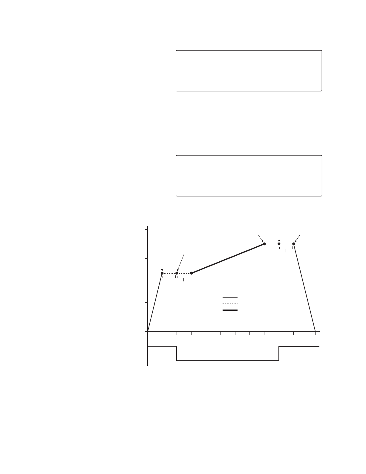
Lake Shore Model 620/622/623/647 Magnet Power Supply User’s Manual
2. Enter these parameters in the Automatic Mode Screen:
MAG START: Magnet Start Current (only if
LAST END is unknown). For this example,
we assume an initial MPS hook-up to this
magnet and a previous magnet charge to
20 A.
MGT END: Magnet End Current. Enter 30
A.
AUTOMATIC MODE:
¤MGT START
MGT END
MGT RATE
PERS RATE
LAST END
PERSISTENCE
RUN ¥
: 0.000A
: 0.000A
: 1.000A/S
: 1.000A/S
: 0.000A
: <OFF>
OUTPUTS: *
+0.000A
+0.001V
STANDBY
MGT RATE: Magnet Charging Rate. Base this figure on the maximum magnet current supplied by the
magnet manufacturer. For this example, enter 0.4 A/S (amperes per second).
PERS RATE: Persistence Switch Charging Rate. Base this figure on the maximum Persistence Switch
current (generally much higher than the magnet charging rate). Anything over approximately 20 A/S
appears instantaneous. For this example, enter 4 A/S.
3. Enter the following parameters in the Automatic Delay Screen (Function Menu 3).
RUN UP: The time between initial ramp up
to current and PSH activation (Persistence
Mode OFF). Enter 5 seconds.
PERS OFF: The time between PSH
activation (Persistence Mode OFF) and
AUTOMATIC MODE DELAYS:
¤RUN UP
PERS OFF
RAMP END
PERS ON
: 60 S
: 60 S
: 60 S
: 60 S
OUTPUTS: *
+1.999A
+0.001V
LVL: +14.4 in
FLD: +63.48 kG
initial ramp to setpoint. Enter 5 seconds.
RAMP END: The time between ramp up to setpoint and PSH deactivation (Persistence Mode ON). Enter
5 seconds.
PERS ON: The time between PSH deactivation (Persistence Mode ON) and initial ramp back to zero.
Enter 5 seconds.
4. Return to the Automatic
Mode Screen. Move to the
RUN line, then toggle to
activate Automatic Mode.
The MPS automatically runs
through the cycle as defined,
providing messages on the
AUTOMATIC MODE
35
30
MGT
START
25
20
Persistence Off
(PSH On)
MGT
END
Persistence On
(PSH Off)
RAMP
PERS
END
ON
Delay
Delay
LAST
END
bottom line of the display to
RAMP
detail the current step of the
cycle. When complete, the
display returns to
STANDBY.
After determining proper system
15
10
MPS Current Output (amperes)
5
UP
Delay
PERS
OFF
Delay
PERS RATE Ramp
Delay
MGT RATE Ramp
Delay times, it is unnecessary to
visit the Delay Screen each time;
the delays store in non-volatile
memory. After the MPS
completes the cycle once, it
0
ON
5
10
15
20
25
30
35
40
45
Time (seconds)
50
stores the ending current value
to LAST END. To make
subsequent changes to magnet
current simply enter a new MGT
OFF
Persistence
Mode Status
Figure 3-2 Typical Automatic Mode Cycle
END setpoint.
57.5
To pause a ramp or skip a time out, press either the Data Entry up or down key. To abort the operation, press
Escape. After an abort, <RUN> continues an automatic process from where it left off.
3-10
Operation
Page 37

Lake Shore Model 620/622/623/647 Magnet Power Supply User’s Manual
3.9 DITHERING IN AUTOMATIC MODE
Dithering is a means of arriving at the magnet current by executing excursions around the final current which
decay to zero in a specified dwell (delay) time.
For example, suppose the final magnet current (MGT END) is 100 amperes, the maximum dither is 0.5%, and
the Dither Delay is 30 seconds. The operation in the Automatic Mode proceeds the same as in Paragraph 3.8
up to the time that the magnet current ramps. The current in the magnet ramps to 100 * (1 + 0.005) = 100.5
amperes, which is 0.5% above the final magnet current. When the current reaches 100.5 amperes, it dwells
for 30 seconds at that current. After the 30 seconds, the current ramps at the MGT RATE to 100 *(1 - .0025) =
99.75 amperes, that is, half of the 0.5% in the opposite direction. The 30 second dwell begins when the
current reaches 99.75 amperes. The process continues at 100 * (1 + 0.00125) = 100.125 amperes, then 100 *
(1 - 0.000625) = 99.9375 amperes, then 100 * (1 + 0.0003125) = 100.031 amperes, and finally 100 amperes.
To access the dithering feature, turn ON (up
position) switch 5 of the rear panel CAL AND ID DIP
switches. Select DELAY/DITHER from Function
Menu 3 to display the AUTOMATIC MODE DELAY
screen shown to the right.
AUTOMATIC MODE DELAYS:
¤RUN UP
PERS OFF
RAMP END
PERS ON
DITHER
DITHER
DITHER
: 60 S
: 60 S
: 60 S
: 60 S
: 60 S
: +0.50%
: <OFF> ¥
OUTPUTS: *
+0.000A
+0.000V
To enable dithering, move the cursor to the last line
using the Up/Down cursor keys. Press either the
Data Entry up or down key to toggle the Dither
Feature on and off. Default is off. For our example,
the DITHER (delay) changes to 30 S from the
default 60 S. The dither of 0.5% is the default. If a
Dither of 1% were entered, the process would
AUTOMATIC MODE:
¤MGT START
MGT ENG
MGT RATE
PERS RATE
LAST END
PERSISTENCE
<DITHER = 0.05%>
:+
100.000A
:+
:+
:+
:+
:
10.000A
1.000A
1.000A
10.000A
<OFF>
OUTPUTS: *
+100.500A
+0.001V
20
¥ TO SKIP
produce 1% over the MGT END, then -0.5% under,
+0.25% over, -0.125% under, 0.0625% over and finally the MGT END selected.
The last line of the Automatic Mode screen shows the stage of the dithering. The screen above indicates the
first current of the dithering at 0.5% above the 100 amperes with 20 seconds left in the Dither delay. Press
either the Data Entry up or down key to skip the delay and ramp immediately to the next current in the dither.
Operation
3-11
Page 38

Lake Shore Model 620/622/623/647 Magnet Power Supply User’s Manual
This Page Intentionally Left Blank.
3-12
Operation
Page 39

Lake Shore Model 620/622/623/647 Magnet Power Supply User’s Manual
CHAPTER 4
REMOTE OPERATION
4.0. GENERAL
Either of two computer interfaces on the optional 6224 card permit remote MPS operation: the IEEE-488
Interface (Paragraph 4.1) and the Serial Interface (Paragraph 4.2). Use only one of the interfaces at a time.
The two interfaces share a common set of commands described in Paragraph 4.3. For further information on
RS-485 Mainframe Control Bus Operation, see Appendix C.
4.1. IEEE-488 INTERFACE
The IEEE-488 Interface is an instrumentation bus with hardware and programming standards that simplify
instrument interfacing. The MPS IEEE-488 Interface complies with the IEEE-488.2-1987 standard and
incorporates the functional, electrical, and mechanical specifications of the standard unless otherwise
specified in this manual.
All instruments on the interface bus perform one or more of the interface functions of TALKER, LISTENER, or
BUS CONTROLLER. A TALKER transmits data onto the bus to other devices. A LISTENER receives data
from other devices through the bus. The BUS CONTROLLER designates to the devices on the bus which
function to perform. The MPS performs the functions of TALKER and LISTENER but cannot be a BUS
CONTROLLER. The BUS CONTROLLER is the digital computer which tells the MPS which functions to
perform.
Below are MPS IEEE-488 interface capabilities:
• SH1: Source handshake capability • SR1: Service request capability
• RL1: Complete remote/local capability • AH1: Acceptor handshake capability
• DC1: Full device clear capability • PP0: No parallel poll capability
• DT0: No device trigger capability
• C0: No system controller capability
• T5: Basic TALKER, serial poll capability, talk only, unaddressed to talk if addressed to listen
• L4: Basic LISTENER, unaddressed to listen if addressed to talk
4.1.1 IEEE-488 Interface Settings
To use the IEEE-488 interface, the user must set
the IEEE Address and Terminators. Press the
Function Menu key, then press the key
corresponding to INTERFACE SETUP to display the
Interface Setup screen. Use the cursor keys to
move the arrow indicator to IEEE ADD and
INTERFACE SETUP:
¤ IEEE ADD
TRMS/EOI
RS232C
CB DEF
CB ADD
VW ANGLE
MF ID
: 12
: (CR LF) EOI
: 9600,N,8,1
: 9600,0,7,1
: 0
: 9
: 622 (1)
¥
¥
¥
¥
¥
OUTPUTS: *
+1.999A
+0.001V
TRMS/EOI.
IEEE ADD: 1 to 30
Use the Data Entry up or down arrows to increment or decrement the IEEE Address. The default value is 12.
The range of choices is from 1 to 30.
TRMS/EOI: CR LF, LF CR, DAB, LF, with or without EOI
Use the Data Entry up or down arrows to cycle through the following choices: (CR LF) EOI, (LF CR) EOI,
(DAB) EOI, (LF) EOI, (CR LF), (LF CR), (DAB), (LF). If turned on, End Or Identify (EOI) is asserted during the
last byte of a multibyte transfer. The default is Carriage Return and Line Feed (CR LF) with EOI ON.
Remote Operation
4-1
Page 40

Lake Shore Model 620/622/623/647 Magnet Power Supply User’s Manual
4.1.2 IEEE-488 Command Structure
The Model 622/623 supports several command types. There are three groups of commands:
1. Bus Control – see Paragraph 4.1.2.1.
a. Universal
(1) Uniline
(2) Multiline
b. Addressed Bus Control
2. Common – see Paragraph 4.1.2.2.
3. Interface and Device Specific – see Paragraph 4.1.2.3.
4.1.2.1 Bus Control Commands
A Universal Command addresses all devices on the bus. Universal Commands include Uniline and Multiline
Commands. A Uniline Command (Message) asserts only a single signal line. The MPS recognizes two of
these messages from the BUS CONTROLLER: Remote (REN) and Interface Clear (IFC). The MPS sends
one Uniline Command: Service Request (SRQ).
REN (Remote) – Puts the MPS into remote mode.
IFC (Interface Clear) – Stops current operation on the bus.
SRQ (Service Request) – Tells the bus controller that the MPS needs interface service.
A Multiline Command asserts a group of signal lines. All devices equipped to implement such commands do
so simultaneously upon command transmission. These commands transmit with the Attention (ATN) line
asserted low. There are two Multiline commands recognized by the MPS:
LLO (Local Lockout) – Prevents the use of instrument front panel controls.
DCL (Device Clear) – Clears MPS interface activity and puts it into a bus idle state.
Finally, Addressed Bus Control Commands are Multiline commands that must include the MPS listen address
before the instrument responds. Only the addressed device responds to these commands. The MPS
recognizes three of the Addressed Bus Control Commands:
SDC (Selective Device Clear) – The SDC command performs essentially the same function as the DCL
command except that only the addressed device responds.
GTL (Go To Local) – The GTL command is used to remove instruments from the remote mode. With some
instruments, GTL also unlocks front panel controls if they were previously locked out with the LLO command.
SPE (Serial Poll Enable) and SPD (Serial Poll Disable) – Serial polling accesses the Service Request
(SRQ) Status Register. This status register contains important operational information from the unit requesting
service. The SPD command ends the polling sequence.
4.1.2.2 Common Commands
Common Commands are addressed commands which create commonalty between instruments on the bus.
All instruments that comply with the IEEE-488 1987 standard share these commands and their format.
Common commands all begin with an asterisk. They generally relate to “bus” and “instrument” status and
identification. Common query commands end with a question mark (?). See Paragraph 4.3 for a complete
listing of all MPS common commands.
4.1.2.3 Interface and Device Specific Commands
Device Specific Commands are addressed commands. The MPS supports a variety of Device Specific
commands to program instruments remotely from a digital computer and to transfer measurements to the
computer. Most Device Specific Commands perform functions also performed from the front panel. This
section discusses Common and Device Specific commands. Device Specific Commands consist of Interface,
Display, Channel, Control Process and Curve commands. See Paragraph 4.3 for a complete listing of all MPS
interface and device specific commands.
4.1.3 Status Registers
There are two status registers: the Status Byte Register (Paragraph 4.1.3.1), and the Standard Event Status
Register (Paragraph 4.1.3.2).
4-2
Remote Operation
Page 41
Lake Shore Model 620/622/623/647 Magnet Power Supply User’s Manual
4.1.3.1 Status Byte and Service Request Enable Registers
The Status Byte Register consists of a single data byte containing seven bits of MPS status information.
STATUS BYTE REGISTER FORMAT
7 6 5 4 3 2 1 0
Bit
128 64 32 16 8 4 2 1 Weighting
SDR SRQ ESB OVP ERR RSC LIM ODR
Bit Name
If the Service Request is enabled, any bits that are set cause the MPS to pull the SRQ management low to
signal the BUS CONTROLLER. These bits reset to zero upon a serial poll of the Status Byte Register.
The Service Request Enable Register inhibits or enables any of the status reports in the Status Byte Register.
The *SRE command sets the bits. A bit that is set enables its function. Inhibit these reports by turning OFF
their corresponding bits in the Service Request Enable Register. Refer to the *SRE discussion.
Setting Data Ready (SDR) Bit (7). When set, the MPS resets current and voltage to 0 A and 1 V because of
OVP or RI activity.
Service Request (SRQ) Bit (6). Determines whether the MPS is to report via the SRQ line and five bits
determine which status reports to make. If bits 0, 1, 2, 3, 4 and/or 5 are set, then the corresponding bit in the
Status Byte Register is set. The MPS produces a service request only if bit 6 of the Service Request Enable
Register is set. If disabled, the Status Byte Register can still be read by the BUS CONTROLLER by means of
a serial poll (SPE) to examine the status reports, but the Service Request does not interrupt the BUS
CONTROLLER. The *STB common query reads the Status Byte Register but does not clear the bits. Certain
bits in the Status Byte Register continually change. Above are bit assignments in the Status Byte Register.
These reports occur only if the bits are enabled in the Service Request Enable Register.
Event Status (ESB) Bit (5). When set, it indicates if one of the bits from the Standard Event Status Register
has been set. (Refer to Paragraph 4.1.4.2.)
Overvoltage Protection (OVP) Bit (4) Indicates overvoltage (quench) protection circuit activation.
Error (ERR) Bit (3). Indicates operation error. The error displays on the front panel and can be read using the
*TST? Command.
Ramp Segment Complete (RSC) Bit (2). Indicates active ramp segment completion.
Limit Exceeded (LIM) Bit (1). Indicates a new current or voltage exceeds the current or compliance voltage
limit. Read the new setting with the ISET? or VSET? commands.
Output Data Ready (ODR) Bit (0). When set, makes current and voltage readings available.
4.1.3.2 Standard Event Status and Standard Event Status Enable Registers
The Standard Event Status Register supplies various conditions of the instrument.
STANDARD EVENT STATUS REGISTER FORMAT
7 6 5 4 3 2 1 0
Bit
128 64 32 16 8 4 2 1 Weighting
PON
not used
CME EXE DDE QYE
not used
OPC
Bit Name
Bits 2 and 6 are not used. The reports of this register occur only if the bits are enabled in the Standard Event
Status Enable Register along with bit 5 of the Service Request Enable Register.
Remote Operation
4-3
Page 42

Lake Shore Model 620/622/623/647 Magnet Power Supply User’s Manual
The Standard Event Status Enable Register enables any of the Standard Event Status Register reports. The
Standard Event Status Enable command (*ESE) sets the Standard Event Status Enable Register bits. Set a
bit to enable its function. To set a bit, send the *ESE command with the bit weighting for each bit to set added
together. See the *ESE command for further details.
The Standard Event Status Enable Query, *ESE?, reads the Standard Event Status Enable Register. *ESR?
reads the Standard Event Status Register. Once this register is read, all bits are reset to zero.
Power On (PON) Bit (7). This bit is set when the power cycles from OFF to ON.
Command Error (CME) Bit (5). Set upon detection of a command error since the last reading. This means
the instrument could not interpret the command due to a syntax error, unrecognized header, unrecognized
terminators, or unsupported command.
Execution Error (EXE) Bit (4). Set upon detection of an execution error. Occurs when the instrument is
instructed to do something outside its capabilities.
Device Dependent Error (DDE) Bit (3). Reserved for future use.
Query Error (QYE) Bit (2). Indicates a query error. Occurs rarely and involves loss of data due to a full output
queue.
Operation Complete (OPC) Bit (0). Generated in response to the *OPC (operation complete) common
command. It indicates MPS completion of all selected pending operations.
4.1.4 Example IEEE Setup and Program
Below is an example of how to setup and run a simple program using the built-in MPS IEEE-488 Interface. It
does not reflect every hardware/software configuration found in the field. This example uses the National
Instruments GPIB - PCII/IIA card and QuickBasic 4.0 or 4.5 on a PC compatible.
4.1.4.1 GPIB Board Installation
Use the following procedure to install the GPIB Board.
1. Install GPIB-PCII/IIA card using National Instruments instructions.
2. Install NI - 488.2 software (for DOS). Version 2.1.1 was used for the example.
3. Verify that config.sys contains the command: device = C:\GPIB.COM
4. Reboot the computer.
5. Run IBTEST to test software configuration. Do not install the instrument before running IBTEST.
6. Run IBCONF to configure the GPIB - PCII/IIA board and dev 12. Set the EOS byte to 0AH. See setup in
Fig 4-1. IBCONF modifies gpib.com.
7. Connect the instrument to the interface board and power up the instrument. Verify the address as 12 and
the terminators as CR LF.
4.1.4.2 Run The Example QuickBasic Program
Use the following procedure to run the QuickBasic Program.
1. Copy c:\gpib-pc\Qbasic\qbib.obj to the QuickBasic directory (QB4).
2. Change to the QuickBasic directory and type: link /q qbib.obj,,,bqlb4x.lib where x = 0 for
QB4.0 and 5 for QB4.5 This one-time only command produces the library file qbib.qlb. The procedure is
found in the National Instruments QuickBasic readme file Readme.qb.
3. Start QuickBasic. Type: qb /l qbib.qlb. Start QuickBasic in this way each time the IEEE interface is
used to link in the library file.
4. Create the IEEE example interface program in QuickBasic. See Table 4-1. Name the file “ieeeexam.bas”
and save.
5. Run the program.
4-4
Remote Operation
Page 43

Lake Shore Model 620/622/623/647 Magnet Power Supply User’s Manual
4.1.5 Notes On Using the IEEE Interface
• The term "free field" indicates a floating decimal point that may be placed any appropriate place in the
string of digits.
• [term] indicates where the user places terminating characters or where they appear on a returning
character string from the MPS.
• To chain commands together, insert a semi-colon, comma, or blank space between them. Some
programming languages allow only blank spaces to chain. Multiple queries cannot be chained. The MPS
responds to the last query entered when addressed as a talker.
• Queries generally use the same syntax as an associated setting command followed by a question mark.
They most often return the same information that is sent. Some queries have no command form.
• Leading zeros and zeros following a decimal point are unneeded in a command string, but they are sent in
response to a query. A leading “+” is not required, but a leading “–” is required.
• As characters are received over the interface, they store in a buffer with a length of 95 characters. After
receiving the terminators, any new parameters are stored. The Mainframe requires about 100 msec to
store new parameters before receiving any new commands.
• The Mainframe implements new parameters and updates measurement data once per 500 msec operation
cycle (noted by the blinking asterisk to the left of the mode status). Sending new parameters or requesting
data at a rate faster than 2 Hz is not recommended.
Table 4-1 Sample BASIC IEEE-488 Interface Program
' IEEEEXAM.BAS EXAMPLE PROGRAM FOR IEEE-488 INTERFACE
'
' This program works with QuickBasic 4.0/4.5 on an IBM PC or compatible.
'
' The example requires a properly configured National Instruments GPIB-PC2 card. The REM
' $INCLUDE statement is necessary along with a correct path to the file QBDECL.BAS.
' CONFIG.SYS must call GPIB.COM created by IBCONF.EXE prior to running Basic. There must
' be QBIB.QBL library in the QuickBasic Directory and QuickBasic must start with a link
' to it. All instrument settings are assumed to be defaults: Address 12, Terminators
' <CR> <LF>, and EOI active.
'
' To use, type an instrument command or query at the prompt. The command transmits to the
' instrument and the MPS receives and displays the response. If no query is sent, the
' instrument responds to the last query received. Type "EXIT" to exit the program. NOTE: The
' INPUT instruction accepts no commas as part of an input string. If a comma appears in an
' instrument command, replace it with a space.
'
REM $INCLUDE: 'c:\gpib-pc\qbasic\qbdecl.bas 'Link to IEEE calls
CLS 'Clear screen
PRINT "IEEE-488 COMMUNICATION PROGRAM"
PRINT
CALL IBFIND("dev12", DEV12%) 'Open communication at address 12
TERM$ = CHR$(13) + CHR$(10) 'Terminators are <CR><LF>
LOOP2: IN$ = SPACE$(2000) 'Clear for return string
INPUT "ENTER COMMAND (or EXIT):"; CMD$ 'Get command from keyboard
CMD$ = UCASE$(CMD$) 'Change input to upper case
IF CMD$ = "EXIT" THEN END 'Get out on Exit
CMD$ = CMD$ + TERM$
CALL IBWRT(DEV12%, CMD$) 'Send command to instrument
CALL IBRD(DEV12%, IN$) 'Get data back each time
ENDTEST = INSTR(IN$, CHR$(13)) 'Test for returned string
IF ENDTEST > 0 THEN 'String is present if <CR> is seen
IN$ = MID$(IN$, 1, ENDTEST - 1) 'Strip off terminators
PRINT "RESPONSE:", IN$ 'Print return string
ELSE
PRINT "NO RESPONSE" 'No string present if timeout
END IF
GOTO LOOP2 'Get next command
Remote Operation
4-5
Page 44
Lake Shore Model 620/622/623/647 Magnet Power Supply User’s Manual
National Instruments GPIB0 Configuration GPIB-PC2/2A Ver 2.1
Primary GPIB Address ..................→0 ↑ Select the primary GPIB address by
Secondary GPIB Address .............NONE using the left and right arrow keys.
Timeout setting..............................10sec
This address is used to compute the
Terminate Read on EOS...............Yes talk and listen addresses which
Set EOI with EOS on Writes .........Yes identify the board or device on the
Type of compare on EOS..............7-Bit GPIB. Valid primary addresses range
EOS byte.......................................0Ah from 0 to 30 (00H to 1EH).
Send EOI at end of Write ..............Yes
* Adding 32 to the primary address
System Controller..........................Yes forms the Listen Address (LA).
Assert REN when SC....................No * Adding 64 to the primary address
Enable Auto Serial Polling.............No forms the Talk Address (TA).
Enable CIC Protocol......................No
Bus Timing ....................................500nsec EXAMPLE: Selecting a primary
Parallel Poll Duration.....................Default address of 10 yields the following:
Use this GPIB board......................Yes 10 + 32 = 42 (Listen address)
Board Type....................................PCII 10 + 64 = 74 (Talk address)
Base I\O Address ..........................02B8h ↓
F1: Help F6: Reset Value F9/Esc: Return to Map Ctl PgUp/PgDn: Next/Prev Board
National Instruments DEV12 Configuration GPIB-PC2/2A Ver 2.1
Primary GPIB Address ..................→0 ↑ Select the primary GPIB address by
Secondary GPIB Address .............NONE using the left and right arrow keys.
Timeout setting..............................10sec
This address is used to compute the
Terminate Read on EOS...............Yes talk and listen addresses which
Set EOI with EOS on Writes .........Yes identify the board or device on the
Type of compare on EOS..............7-Bit GPIB. Valid primary addresses range
EOS byte.......................................0Ah from 0 to 30 (00H to 1EH).
Send EOI at end of Write ..............Yes
* Adding 32 to the primary address
Enable Repeat Addressing ...........Yes forms the Listen Address (LA).
* Adding 64 to the primary address
forms the Talk Address (TA).
EXAMPLE: Selecting a primary
address of 10 yields the following:
10 + 32 = 42 (Listen address)
10 + 64 = 74 (Talk address)
↓
F1: Help F6: Reset Value F9/Esc: Return to Map Ctl PgUp/PgDn: Next/Prev Board
Figure 4-1 Typical National Instruments GPIB Configuration from IBCONF.EXE
4-6
Remote Operation
Page 45
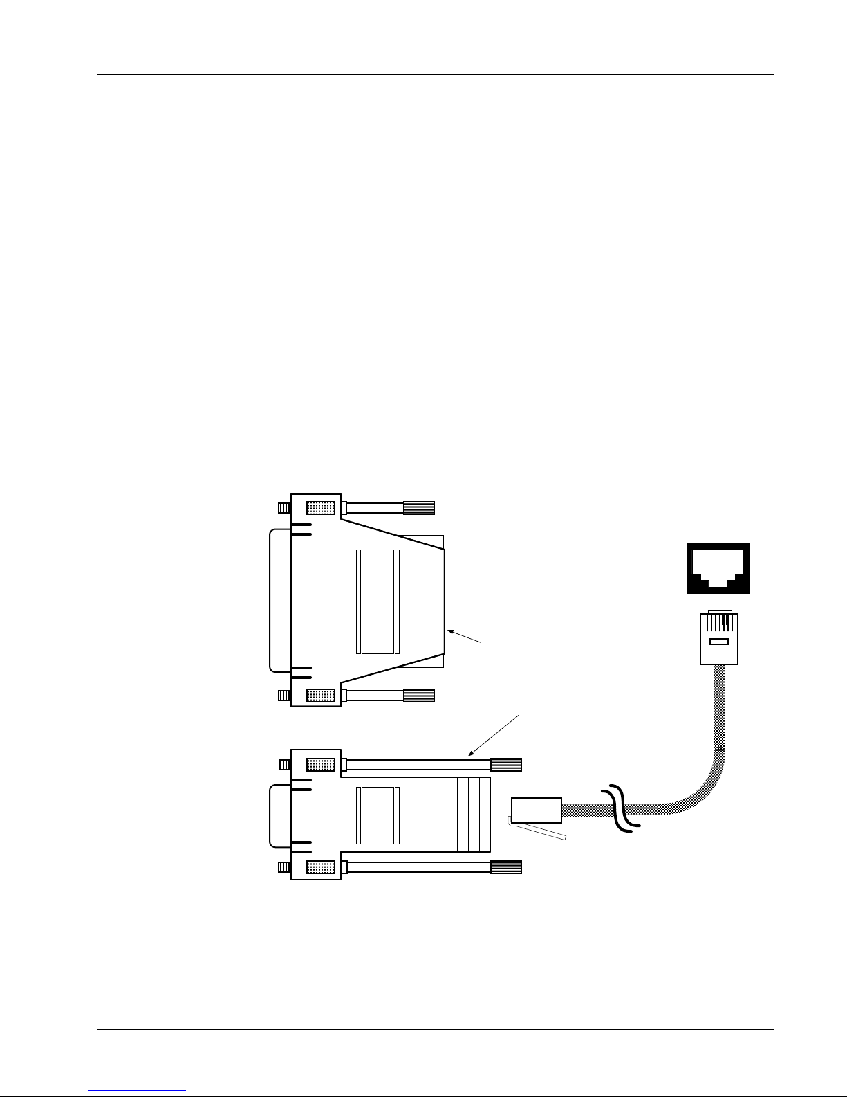
Lake Shore Model 620/622/623/647 Magnet Power Supply User’s Manual
4.2 SERIAL I/O INTERFACE
RS-232C is a standard of the Electronics Industries Association (EIA) and one of the most common interfaces
between a computer and electronic equipment. The Customer supplied computer must have a Serial Interface
port. The MPS Serial Interface complies with the electrical format of the RS-232C Interface Standard. A Serial
Interface between the computer and the MPS permits remote monitoring and control of MPS control functions,
which in turn controls MPS operation. See Figure 4-2.
The Serial Interface can both transmit and receive information. In transmit (Tx) mode, the instrument converts
parallel information to serial and sends it over a cable up to 50 feet long (or longer with proper shielding). In
receive (Rx) mode, the instrument converts serial information back to parallel for processing.
See Paragraph 4.2.1 for Serial Interface hardware configuration and adapters, Paragraph 4.2.2 for Serial
Interface settings, and Paragraph 4.2.3 for a sample BASIC program to establish communications between
the computer and the MPS.
The Serial Interface shares Device Specific commands with the IEEE-488 interface listed in Paragraph 4.3.
However, without the advantage of the IEEE-488 Architecture, there are several limitations:
• The ∗OPC and ∗RST Common Commands are not supported.
• The END Bus Control Command is not supported.
• Terminators are fixed to CRLF.
• A query must be added to the end of a command string if the MPS must return information. (Over
IEEE-488, the last query response is sent when addressed to talk.) For example: “ISET 10;ISET?”
would set the output current to 10 A and immediately query the output current setting.
LSCI Model
2002 RJ-11
To customer-supplied
computer with DB-25
Serial Interface
Connector configured
as DCE. If the
to DB-25
Adapter
Serial Interface
Output on rear of
MPS
SERIAL I/OSERIAL I/O
1
interface is DTE, a Null
Modem Adapter is
required to exchange
Transmit and Receive
lines.
To customer-supplied
LSCI Model 2003 RJ-11
to DE-9 Adapter
The Model 2001, 2002, and 2003 are
options available from Lake Shore.
Use whichever adapter that matches
your computer serial interface
connector. Pin outs are described in
Paragraph 5.7.
computer with DE-9
Serial Interface
Connector configured
as DTE. If the interface
is DCE, a Null Modem
Adapter is required to
exchange Transmit and
LSCI Model 2001 RJ-11
Cable Assembly
Receive lines.
C-MPS-4-2.eps
Figure 4-2. Serial Interface Adapters
Remote Operation
4-7
Page 46
Lake Shore Model 620/622/623/647 Magnet Power Supply User’s Manual
4.2.1 Serial Interface Hardware Configuration
Below is a technical description of the 6224 option card for the Serial Interface configuration. (Note: See
Appendix C for Serial Interface on CMP.) Table 4.2 defines communication parameters. Terminators are fixed
to Carriage Return (CR) and Line Feed (LF).
The serial interface connector is a standard 6-wire RJ-11 (telephone) jack. Lake Shore offers the Model 2001
10-foot Cable Assembly, Model 2002 RJ-11 to DB-25 Adapter, and the Model 2003 RJ-11 to DE-9 Adapter.
See Chapter 5 for Serial I/O connector and adapter pinouts, and for RJ-11 pinouts. See Paragraph 5.7 for
adapter wiring.
Table 4-2 Serial Interface Specifications
Transmission: Three-W ire Bits per Character: 1 Start, 8 Data, 1 Stop
Baud Rate: 300, 1200 or 9600 Timing Format: Asynchronous
Parity Type: None Connector: Two RJ-11 Modular Socket
Fixed Terminator: CR (0DH) LF (0AH) Transmission Mode: Half Duplex
Data Interface Levels: Transmits & Receives Using EIA Voltage Levels
4.2.2 Serial Interface Settings
To use the Serial Interface, set the Baud rate. Press
the Function Menu key, then press the function key
corresponding to INTERFACE SETUP to display the
screen to the right. Use the cursor keys to move the
arrow indicator to RS232C. Press the Data Entry up
or down arrows to cycle between 300, 1200, or 9600
INTERFACE SETUP:
¤ IEEE ADD
TRMS/EOI
RS232C
CB DEF
CB ADD
VW ANGLE
MF ID
: 12
: (CR LF) EOI
: 9600,N,8,1
: 9600,0,7,1
: 0
: 9
: 622 (1)
¥
¥
¥
¥
¥
OUTPUTS: *
+1.999A
+0.001V
Baud. The remainder of the parameters are fixed at
No Parity, 8 Data Bits, and 1 Stop Bit.
4.2.3 Sample BASIC Serial Interface Program
The QuickBASIC V4.0 program in Table 4.3 is a sample interactive serial poll routine for the MPS Serial
Interface. Below are typical examples using this BASIC program. (User input is in bold type.)
ENTER COMMAND? *IDN? Identification Query. Returns manufacturer, model number,
0, and Firmware Date.
LSCI,622,0,120193
ENTER COMMAND? ISET 25;IOUT? Output Current Setting and Query. Instructs unit to set
current to 25 amps and then asks for current reading.
+24.9975A
ENTER COMMAND? OVP? Overvoltage (Quench) Protection Circuit Status Query. Unit
returns setting, where 0 = Off and 1 = On.
0
ENTER COMMAND? RI? Remote Inhibit Status Query. Unit returns setting, where
0 = Inactive and 1 = Active.
0
ENTER COMMAND? MODE? Mode Status Query. Instrument returns mode, where
0 = Local, 1 = Remote, or 2 = Remote with Lockout.
1
4-8
Remote Operation
Page 47

Lake Shore Model 620/622/623/647 Magnet Power Supply User’s Manual
4.2.4 Notes On Using The Serial Interface
• To chain commands together, insert a semi-colon (;) between them. Multiple queries cannot be chained.
• Queries use the same syntax as the associated setting command followed by a question mark (?). They
usually return the same information that is sent.
• Add a query to the end of a command string if the controller must return information. For example, RMP
0;RMP? commands the MPS to pause the ramp then return the ramp status to confirm the change.
• The MPS returns nothing queries without a “?" and ignores misspelled commands and queries.
• The term "free field" indicates a floating decimal point that can be placed at any appropriate place in the
string of digits.
• Leading zeros and zeros following a decimal point are unneeded in a command string, but they are sent in
response to a query. A leading “+” is not required, but a leading “–”
is required.
• [term] indicates where the user places terminating characters or where they appear on a returning character
string from the MPS.
' SEREXAM.BAS EXAMPLE PROGRAM FOR SERIAL INTERFACE
' This program works with QuickBasic 4.0/4.5 or Qbasic on an IBM PC or compatible
' with a serial interface. It uses the COM1 communication port at 9600 BAUD. Enter
' an instrument command or query at the prompt. The command transmits to the
' instrument which displays any query response. Type "EXIT" to exit the program.
' NOTE: The INPUT instruction in this example accepts no commas as part of an input
' string. If a comma appears in an instrument command, replace it with a space.
'
CLS 'Clear screen
PRINT " SERIAL COMMUNICATION PROGRAM"
PRINT
TIMEOUT = 2000 'Read timeout (may need more)
BAUD$ = "9600"
TERM$ = CHR$(13) + CHR$(10) 'Terminators are <CR><LF>
OPEN "COM1:" + BAUD$ + ",N,8,1,RS" FOR RANDOM AS #1 LEN = 256
LOOP1: INPUT "ENTER COMMAND (or EXIT):"; CMD$ 'Get command from keyboard
CMD$ = UCASE$(CMD$) 'Change input to upper case
IF CMD$ = "EXIT" THEN CLOSE #1: END 'Get out on Exit
CMD$ = CMD$ + TERM$
PRINT #1, CMD$; 'Send command to instrument
IF INSTR(CMD$, "?") <> 0 THEN 'Test for query
RS$ = "" 'If query, read response
N = 0 'Clr return string and count
Table 4-3. Sample BASIC Serial Interface Program
WHILE (N < TIMEOUT) AND (INSTR(RS$, TERM$) = 0) 'Wait for response
IN$ = INPUT$(LOC(1), #1) 'Get one character at a time
IFIN$=""THENN=N+1ELSEN=0'Add 1 to timeout if no chr
RS$ = RS$ + IN$ 'Add next chr to string
WEND 'Get chrs until terminators
IF RS$ <> "" THEN 'See if return string is empty
RS$ = MID$(RS$, 1, (INSTR(RS$, TERM$) - 1)) 'Strip off terminators
PRINT "RESPONSE:"; RS$ 'Print response to query
ELSE
PRINT "NO RESPONSE" 'No response to query
END IF
END IF 'Get next command
GOTO LOOP1
Remote Operation
4-9
Page 48

Lake Shore Model 620/622/623/647 Magnet Power Supply User’s Manual
4.3 SUMMARY OF IEEE-488/SERIAL INTERFACE COMMANDS
Below is an alphabetical list of IEEE-488/Serial Interface commands consisting of Operational Commands
(Paragraph 4.3.1), Interface Commands (Paragraph 4.3.2), Ramping Commands (Paragraph 4.3.3), Current
Zero Commands (Paragraph 4.3.4), Current Step Limit Commands (Paragraph 4.3.5), Computed Field
Commands (Paragraph 4.3.6), and Common Commands (Paragraph 4.3.7).
OPERATIONAL COMMANDS
Cmd Function
ERR? Error Status Summary
IMAX Upper Current Limit
IMAX? Upper Current Limit Query
IOUT? Output Current Query
ISET Output Current Setting
ISET? Output Current Setting Query
IV? Output Summary Query
OVP? Overvoltage Protection Query
RES? Resolution
RI? Remote Inhibit Status Query
VOUT? Output Voltage Query
VSET Compliance Voltage Setting
VSET? Compliance Voltage Setting Query
INTERFACE COMMANDS
Cmd Function
END EOI Status
END? EOI Status Query
MODE Interface Status Mode
MODE? Interface Status Mode Query
TERM Terminator
TERM? Terminator Query
RAMPING COMMANDS
Cmd Function
RAMP Ramp Segment Parameters
RAMP? Ramp Segment Parameters Query
RMP Ramp Status
RMP? Ramp Status Query
SEG Active Ramp Segment
SEG? Active Ramp Segment Query
CURRENT STEP LIMIT COMMANDS
Cmd Function
ISTP Output Current Step Limit
ISTP? Output Current Step Limit Query
ISTPS Output Current Step Limit Status
ISTPS? Output I Step Limit Status Query
STEP? Output I Step Limit Exceeded Query
STEPR1 Output I Step Limit Exceeded Reset
COMPUTED FIELD COMMANDS
Cmd Function
CFPA Program Computed Field/Amp Constant
CFPA? Computed Field/Amp Constant Query
CFUNI Program Computed Field Display Units
CFUNI? Computed Field Display Units Query
CFPS Set Computed Field Display Status
CFPS? Computed Field Status Query
COMMON COMMANDS
Cmd Function
*CLS Interface Clear
*ESE Std. Event Status Enable Reg
*ESE? Std. Event Status Query
*ESR? Std. Event Status Enable Query
*IDN? Identification Query
*OPC Operation Complete
*OPC? Operation Complete Query
*RST Reset Command
*SRE Service Request
*SRE? Service Request Query
*STB? Status Byte Query
*TST? Self Test Query
*WAI Wait-To-Continue
CURRENT ZERO COMMANDS
Cmd Function
IMODE? Current Programming Mode Query
VMODE? Voltage Programming Mode Query
ZI Zero Current Value Status
ZI? Zero Current Value Query
ZIS Zero Current Status
ZIS? Zero Current Status Query
See Chapter 6 for additional IEEE-488 commands for the following MPS Options:
Model 6226/6476 LHe Level and Gaussmeter Input Card . . . . . . . . . . . . . . . . . . Paragraph 6.2
Model 6228 Persistent Switch Heater Output . . . . . . . . . . . . . . . . . . . . . . . Paragraph 6.3
COMMAND (Shortcut Command): Short command description.
Input: Syntax of user input.
Returned: Informational response to query.
Remarks: Explanation and definition of informational response.
4-10
Remote Operation
Page 49

Lake Shore Model 620/622/623/647 Magnet Power Supply User’s Manual
4.3.1 Operational Commands Description
Below is a list of MPS Operational Commands which configure the various functions.
ERR? Error Status Query
Input: ERR?
Returned: [OVP] [RI] [STEP]
Remarks: Returns 0 if the error is inactive or 1 if it is active. Returns three characters plus up to two
terminators.
IMAX Programs Upper Current Limit
Input: IMAX [current] where [current] = a value between 0 and +50 A (620), 0 and +125 A (622),
0 and +155 A (623), or 0 and +72 A (647).
Remarks: Programs the upper (soft) current limit of the MPS. Truncates the value to the 0.001 place. The
initial condition is +000.0000 A. The current limit is always forced to a plus. Setting is limited by
product limits. Control Bus inputs 4 places, display rounds to 0.01 or 0.001 place.
IMAX? Current Limit Query
Input: IMAX?
Returned: A number between 0 and +50 A (620), 0 and +125 A (622), 0 and +155 A (623),
or 0 and +72 A (647).
Remarks: Nine characters plus up to two terminators are returned. Value is shown as
a “+,” but applies to both positive and negative entries.
IOUT? (I?) Output Current Query
Input: IOUT? or I?
Returned: A number between 0 and ±50 A (620), 0 and ±125 A (622), 0 and ±155 A (623),
or 0 and ±72 A (647).
Remarks: Returns nine characters plus up to two terminators.
ISET (I) Enter Output Current
Input: ISET [current] or I [current] where [current] = a value between 0 and ±50 A (620),
0 and ±125 A (622), 0 and ±155 A (623), or 0 and ±72 A (647).
Remarks: Value is truncated to the 0.001 place. Initial condition is +000.0000 A. Setting is limited by
IMAX. Control Bus inputs 4 places, display rounds to 0.01 or 0.001 place.
ISET? Output Current Setting Query
Input: ISET?
Returned: A number between 0 and ±50 A (620), 0 and ±125 A (622), 0 and ±155 A (623),
Remarks: Returns nine characters plus up to two terminators.
or 0 and ±72 A (647).
IV? Output Summary Query
Input: IV?
Returned: [IOUT], [VOUT], [STB], [I MODE], [V MODE]
Remarks: Returns twenty-seven characters plus up to two terminators.
Remote Operation
4-11
Page 50

Lake Shore Model 620/622/623/647 Magnet Power Supply User’s Manual
OVP? Overvoltage (Quench) Protection Circuit Status Query
Input: OVP?
Returned: 0 if the circuit is inactive, or 1 if it is active.
Remarks: One character plus up to two terminators are returned.
RES? Resolution Query
Input: RES?
Returned: 0 for low resolution or 1 for high resolution. (This command maintains compatibility with older
Remarks: Returns two characters plus up to two terminators.
MPS versions. Remote interface operation does not change since the remote resolution is
already to the 0.0001 place.)
RI? Remote Inhibit Status Query
Input: RI?
Returned: 0 if the remote inhibit is inactive, or 1 if it is active.
Remarks: One character plus up to two terminators are returned.
VOUT? (V?) Output Voltage Query
Input: VOUT? or V?
Returned: A number between 0 and ±5.000 V (620), 0 and ±30.000 V (622/623),
or 0 and ±32.000 V (647).
Remarks: Returns nine characters plus up to two terminators.
VSET (V) Enter Compliance Voltage
Input: VSET [voltage] or V [voltage] where [voltage]: = a value from 0 and ±5.000 V (620),
0 and ±30.000 V (622/623), or 0 and ±32.000 V (647).
Remarks: The initial condition is +00.0000 V. The voltage setting is always forced to a “+.” Control Bus
inputs 4 places, display rounds to 0.01 or 0.001 place.
VSET? Compliance Voltage Setting Query
Input: VSET?
Returned: A number between 0 and ±5.000 V (620), 0 and ±30.000 V (622/623),
or 0 and ±32.000 V (647).
Remarks: Returns nine characters plus up to two terminators.
4-12
Remote Operation
Page 51

Lake Shore Model 620/622/623/647 Magnet Power Supply User’s Manual
4.3.2 Interface Commands Description
The MPS Interface Commands below help configure IEEE-488 interface compatibility for a variety of computer
equipment.
END Programs MPS Interface EOI (End Or Identify) Status
Input: END [status] where [status] = 0 to enable the EOI, or 1 to disable it.
Remarks: When enabled, the hardware EOI line becomes active with the last byte of a transfer. Not
supported by Control Bus.
END? End Of Identify (EOI) Query
Input: END?
Returned: 0 if EOI is enabled, or 1 if it is disabled.
Remarks: Returns 1 character plus up to 2 terminators. Not supported by Control Bus.
MODE Programs MPS Interface Mode Status
Input: MODE [status] where [status] = 0 for local mode, 1 for remote mode, or 2 for remote mode
with local lockout. Supported in Control Bus operation.
MODE? Interface Mode Status Query
Input: MODE?
Returned: 0 for local mode, 1 for remote mode, or 2 for remote mode with local lockout.
Remarks: Returns 1 character plus up to 2 terminators. Supported by Control Bus.
TERM Programs MPS Interface Terminating Characters
Input: TERM [type] where [type] = 0 for a carriage return and line feed (CR)(LF
1 for a line feed and carriage return (LF)(CR
EOI
2 for a line feed (LF
3 for no terminating characters (DAB
),
EOI
Remarks: Terminating characters are sent when the MPS completes its message on output. They also
identify the end of an input message. Control Bus fixes terminators at (CR)(LF) on receipt and
transmission.
EOI
),
EOI
),
) DAB = Last Data Byte
TERM? Terminator Query
Input: TERM?
Returned: 0 for a carriage return and line feed (CR)(LF
1 for a line feed and carriage return (LF)(CR
2 for a line feed (LF
3 for no terminating characters (DAB
Remarks: Control Bus fixes terminators at (CR)(LF) on receipt and transmission.
EOI
)
EOI
EOI
)
EOI
) DAB = Last Data Byte
)
Remote Operation
4-13
Page 52

Lake Shore Model 620/622/623/647 Magnet Power Supply User’s Manual
4.3.3 Ramping Commands Description
The following MPS Ramping Commands configure the various functions of the ramping features.
RAMP Programs Ramp Segment Parameters
Input: RAMP[segment],[initial ramp current],[final ramp current],[ramp rate],[00],[--:--:--:--]
[segment] = 1. (Future updates will allow up to nine segments.)
where:
[initial ramp current] = 0 and ±50 A (620), 0 and ±125 A (622), 0 and ±155 A (623),
or 0 and ±72 A (647).
[final ramp current] = 0 and ±50 A (620), 0 and ±125 A (622), 0 and ±155 A (623), or
0 and ±72 A (647).
[ramp rate] = 0 to 99.9999 A/S.
[00]: Reserved for future use (Operation to perform). Need not be present for
proper command operation.
[--:--:--:--]: Reserved for future use (DWELL time in days, hours, minutes and
seconds). Does not need to be present for proper command operation.
Remarks: Truncates value to 0.001 place. Enter values with no embedded spaces. Undefined
parameters are set to 0. Control Bus inputs 4 places, display rounds to 0.01 or 0.001 place.
Example: RAMP1,+125.0000,-125.0000,01.0000[term]
Indicates: Ramp Segment = 1;
Initial Ramp Current = +125.0000 A;
Final Ramp Current = -125.0000 A;
Ramp Rate = 01.0000 A/S; commas can be replaced by blanks.
RAMP? Ramp Parameter Query
Input: RAMP?
Returned: Values are the same format as described above for programming in the ramp segments.
Remarks: Returns 48 characters and up to two terminators.
RMP Programs Ramp Status
Input: RMP [ramp status] where
turn on the ramp segment or continue a ramp on hold.
[ramp status] = 0 to turn off (HOLD) the ramp definitely, or 1 to
RMP? Ramp Status Query
Input: RMP?
Returned: 0 for holding, or 1 for ramping.
Remarks: One character plus up to two terminators are returned.
SEG Programs Active Ramp Segment
Input: SEG [segment] where [segment] = 1. (Future updates will allow multiple ramp segments).
SEG? Active Ramp Segment Query
Input: SEG?
Returned: 1. (Future updates will allow multiple ramp segments).
Remarks: Returns one character plus up to two terminator.
4-14
Remote Operation
Page 53

Lake Shore Model 620/622/623/647 Magnet Power Supply User’s Manual
4.3.4 Current Zero Commands Description
The following MPS commands configure the various functions of the current zero features.
IMODE? Current Programming Mode Query
Input: IMODE?
Returned: 0 if I MODE switch is set to EXT, or 1 if set to INT.
Remarks: Returns one character plus up to two terminators. W hen multiple MPS units are present, the
current programming mode of MPS No. 1 is reported.
VMODE? Voltage Programming Mode Query
Input: VMODE?
Returned: 0 if the V MODE switch is set to EXT, or 1 if set to INT.
Remarks: Returns one character plus up to two terminators. W hen multiple MPS units are present, the
voltage programming mode of MPS No. 1 is reported.
ZI Programs Current Zero Value
Input: ZI [current zero] where [current zero] = a value between ±999.9999.
Remarks: Enter this setting after enabling ZI Status. Control Bus inputs 4 places, display rounds to 0.01
or 0.001 place. If a ZI value is entered over the Control Bus, status automatically turns ON.
ZI? Current Zero Value Query
Input: ZI?
Returned: A number between ±999.9999.
Remarks: Returns nine characters plus up to two terminators.
ZIS Programs Current Zero Status
Input: ZIS [status] where [status] = 0 to turn OFF the current zero, or 1 to turn it ON.
Remarks: When the current zero is turned off, the current zero value resets to 0.
ZIS? Current Zero Status Query
Input: ZIS?
Returned: 0 if the current zero is OFF, or 1 if it is ON.
Remarks: Returns one character plus up to two terminators.
Remote Operation
4-15
Page 54

Lake Shore Model 620/622/623/647 Magnet Power Supply User’s Manual
4.3.5 Current Step Limit Commands Description
The following MPS commands configure the various functions of the current step limit features.
ISTP Programs Output Current Step Limit
Input: ISTP [step limit] where [step limit] = a value between 0 and +999.9900.
Remarks: Truncates the value to the 0.001 place. The initial condition is +000.000 A. The step limit is
forced to a plus. Control Bus inputs 4 places, display rounds to 0.01 or 0.001 place.
ISTP? Output Current Step Limit Query
Input: ISTP?
Returned: A number between 0 and +999.9900 A.
Remarks: Returns nine characters plus up to two terminators. Value is shown as a “+”, but applies to both
positive and negative step changes.
ISTPS Programs Output Current Step Limit Status
Input: ISTPS [status] where [status] = 0 to turn OFF output current step limit, or 1 to turn it ON.
Remarks: The initial condition is 0.
ISTPS? Output Current Step Limit Status Query
Input: ISTPS?
Returned: 0 for OFF, or 1 for ON.
Remarks: Returns one character plus up to two terminators.
STEP? Output Current Step Limit Exceeded Query
Input: STEP?
Returned: 0 if the step limit has not been exceeded, or 1 if it has been exceeded.
Remarks: Returns one character plus up to two terminators.
STEPR1 Output Current Step Limit Status Reset
Input: STEPR1
Returned: Nothing
Remarks: When the output current step limit has been exceeded, this command must be issued before
normal operation can be resumed.
4-16
Remote Operation
Page 55

4.3.6 Computed Field Commands Description
The MPS can also display Computed Field rather than current. This is useful with Superconducting magnets
because there is a linear relationship between the current and actual field to a reasonable degree of accuracy.
This feature is not to be confused with the field as measured with the Model 6226 Liquid Helium Level and
Gaussmeter Input Card. The commands and queries below allow users to calculate the same Computed field
in the host computer as is displayed on the MPS front panel.
Lake Shore Model 620/622/623/647 Magnet Power Supply User’s Manual
CFPA Programs Computed Field/Ampere Constant
Input: CFPA [field/ampere] where field/ampere is kG/ampere or tesla/ampere dependent on the
computed field units.
Remarks: Programs the kG/ampere or tesla/ampere constant used primarily in superconducting
magnets. Limited to 9.999 kG/ampere (0.9999 tesla). Value is rounded to 0.001 kG/ampere or
0.0001 tesla/ampere. Be aware of MPS units via the CFUNI? query so as not to be in error by
a factor of 10.
CFPA? Computed Field/Ampere Constant Query
Input: CFPA?
Returned: A number between 0 and 9.999 kG/ampere or 0.9999 tesla/ampere
Remarks: Query units with CFUNI? to verify correct units. Returns 5 character plus up to 2 terminators.
CFUNI Program Computed Field Display Units
Input: CFUNI [Units] where Units = K displays kG, Units = T displays tesla.
Remarks: Enable computed field status with CFPS to display computed field.
CFUNI? Computed Field Units Query
Input: CFUNI?
Returned: Returns K if units = kG, T if units = tesla.
Remarks: Returns 1 character plus up to 2 terminators.
CFPS Set Computed Field Display Status
Input: CFPA [Status] where Status = 0 displays amperes, Status = 1 displays Computed Field.
Remarks: The computed field = kG or tesla based on the CFUNI units.
CFPS? Computed Field Status Query
Input: CFPA?
Returned: 0 = amperes currently displayed, 1 = Computed Field currently displayed.
Remarks: Returns 1 character plus up to 2 terminators.
Remote Operation
4-17
Page 56
Lake Shore Model 620/622/623/647 Magnet Power Supply User’s Manual
4.3.7 Common Commands Description
The MPS Common Commands below are input/output commands defined by the IEEE-488 standard and
shared with other instruments complying with the standard. Common commands begin with “*”.
*CLS Clear Status Register Command
Input: *CLS
Returned: Nothing.
Remarks: Clears the Status Register, but not the instrument. It clears the bits in the Status Byte Register
and the Standard Event Status Register and terminates all pending operations. The
instrument-related command is *RST.
*ESE Enables Status Reports In The Standard Event Status Enable Register
Input: *ESE [bit weighting] where [bit weighting] = the sum of the bit weighting of each bit to be
set. The value can be 000 to 255. See the discussion on registers and below.
Remarks: Each bit is assigned a bit weighting. See the format of the Standard Event Status Register
(given below) to see bit weighting and register placement. Further explanation of each bit is
discussed in the register section following the Common Command Table. See Paragraph
4.1.3.2 for a complete description of status bits.
7 6 5 4 3 2 1 0
Bit
128 64 32 16 8 4 2 1 Weighting
PON
not used
CME EXE DDE QYE
not used
OPC
Bit Name
Example: To set a bit, send the command *ESE with the sum of the bit weighting for each bit
desired. For example, to set bits 0, 3, 4, and 5, send the command *ESE57. 57 is the sum of
the bit weighting for each bit: Bit Weighting
0 1
3 8
4 16
5 32
57
*ESE? Standard Event Status Enable Query
Input: *ESE?
Returned: An integer between 000 and 255.
Remarks: Reads the Standard Event Status Enable Register. The integer returned represents the bits set
in the Standard Event Status Enable Register. It is a sum of the bit weighting of each bit set.
Returns three digits plus up to two terminators.
*ESR? Standard Event Status Register Query
Input: *ESE?
Returned: An integer between 000 and 255.
Remarks: Reads the Standard Event Status Register. The integer returned represents bits set in the
Service Request Enable Register. It is a sum of the bit weighting of each bit set. This Query
supplies various error conditions and whether the MPS has been powered off and on since the
last query. Returns three digits plus up to two terminators.
4-18
Remote Operation
Page 57

Lake Shore Model 620/622/623/647 Magnet Power Supply User’s Manual
*IDN? Identification Query
Input: *IDN?
Returned: Manufacturer, Model Number, Model Serial Number, Firmware Date.
Remarks: Returns seventeen characters plus up to two terminators.
Example: LSCI,622,0,120193[term]
*OPC Operation Complete Status
Input: *OPC
Returned: Nothing.
Remarks: Causes the MPS to set an update cycle counter to 2. Each time through an update cycle,
parameters entered by device dependent commands update and the cycle count decrements.
Two update cycles complete all pending device dependent commands. When this occurs, the
MPS sets the operation complete bit in the Standard Event Status Register (not the
IEEE-488.2 defined operation). Not supported by Control Bus.
*OPC? Operation Complete Status Query
Input: *OPC?
Returned: 0 or 1, where 0 indicates incomplete, 1 indicates complete.
Remarks: Places 1 in the instrument output queue and sets the Operation Complete Bit in the Standard
Event Status Register upon completion of all pending selected device operations. This must be
sent as the last command in a command string. Returns one character plus up to two
terminators. Not supported by Control Bus.
*RST Instrument Reset Command
Input: *RST
Returned: Nothing.
Remarks: Restores MPS to power-up settings just like the DCL and SDC bus commands. The MPS
reverts to the Normal Display Screen, forces ramp status to the Hold mode, and clears any
latched error along with the Status Byte and the Standard Event Status Registers. Not
supported by Control Bus.
Remote Operation
4-19
Page 58
Lake Shore Model 620/622/623/647 Magnet Power Supply User’s Manual
*SRE Enables Status Reports In The Service Request Enable Register
Input: *SRE [bit weighting] where [bit weighting] = the sum (000 to 255) of bit weighting of each
bit to be set. See the discussion on registers and below.
Remarks: Each bit is assigned a bit weighting. See the format of the Status Byte Register (given below)
to see weighting and register placement of bits. See the register section following the Common
Command Table. See Paragraph 4.1.3.1 for a complete description of status bits.
7 6 5 4 3 2 1 0
Bit
128 64 32 16 8 4 2 1 Weighting
SDR SRQ ESB OVP ERR RSC LIM ODR
Bit Name
Example: If a bit in the Service Request Enable Register is set (1), its function is enabled and
reported in the Status Byte Register. For example, to enable bits 1, 2, 4 and 6, send the
command *SRE86. 86 is the sum of the bit weighting for each bit: Bit
Weighting
1 2
2 4
4 16
6 64
86
*SRE? Service Request Enable Query
Input: *SRE?
Returned: An integer from 000-255.
Remarks: Reads the Service Request Enable Register. The integer returned represents the sum of the
bit weighting of each bit set. Returns three digits plus up to two terminators.
*STB? Status Byte Query
Input: *STB?
Returned: An integer from 000-255.
Remarks: Reads the Status Byte Register. The integer returned represents the sum of the bit weighting
of each bit set. Although this query acts like a serial poll, it does not reset the register to all
zeros. Returns three digits plus up to two terminators.
*TST? Self Test Query
Input: *TST?
Returned: 0 = No errors 3 = Reserved 6 = AC High 9 = OI Active
1 = Remote Inhibit Active 4 = STP Error 7 = Rail High
2 = OVP Active 5 = AC Low 8 = Overtemperature Error
A = Setpoint Entry STP B = Rate Entry STP C = OPP (Overpower Protection) Error
Remarks: Causes instrument to report any failures. Returns 1 character plus up to 2 terminators.
*WAI Wait-to-Continue Command
Input: *WAI
Returned: Nothing.
Remarks: The command prevents the instrument from executing any further commands or queries until
4-20
all previous ones have been serviced. This command is accepted but not supported (not the
IEEE-488.2 defined operation). Not supported by the Control Bus.
Remote Operation
Page 59

Lake Shore Model 620/622/623/647 Magnet Power Supply User’s Manual
CHAPTER 5
ERROR MESSAGES AND TROUBLESHOOTING
5.0 GENERAL
This chapter covers Software Error Messages
(Paragraph 5.1), Factory Default Settings (Paragraph 5.2), Calibration Procedure (Paragraph 5.3),
Performance Test (Paragraph 5.4), Rear Panel
Connectors Definition (Paragraph 5.5), IEEE-488
Connector Definition (Paragraph 5.6), and Serial
Interface Cable and Adapters (Paragraph 5.7).
The MPS sounds the alarm and halts operation until
the user presses a Data Entry up or down key to clear
the fault. When the fault clears, the MPS opens the
FLT contacts, silences the alarm, and displays the
normal display.
Remote Inhibit (RI) Detected
5.1 SOFTWARE ERROR MESSAGES
The MPS constantly monitors its circuits for faults
like low or high line voltage, line loss, or internal
temperature and rail faults. Upon detection, the
error and a brief description display. Below are
error messages that may display during normal
operation:
Error 01 – Unwriteable NOVRAM Error
ERROR 01:
AN UNWRITEABLE NOVRAM DATA LOCATION
EXISTS IN THE DISPLAY NOVRAM. THIS
ERROR IS NOT CORRECTABLE BY THE USER.
CONTACT LSCI FOR A REPLACEMENT NOVRAM.
Error 02 – NOVRAM Data Verification Error
ERROR 02:
A NOVRAM DATA VERIFICATION ERROR EXISTS
IN THE DISPLAY NOVRAM. INITIALIZE THE
NOVRAM BY PRESSING THE Esc KEY FOR
10 SECONDS. IF THE ERROR STILL EXISTS,
CONTACT LSCI FOR A REPLACEMENT NOVRAM.
Error 06 – Calibration Data NOVRAM Error
ERROR 06:
A CALIBRATION DATA NOVRAM ERROR EXISTS
IN THE MAINFRAME. MAINFRAME CALIBRATION
MUST BE PERFORMED. CONTACT LSCI.
Output Current Step Limit Exceeded
If the MPS detects an output current change that
exceeds the step limit, it enters Step Limit Mode
and forces MPS output to 0 amps and 1 volt. On
the next display update cycle, the MPS closes the
FLT contacts to indicate the fault, sounds an alarm
about once per second, and displays:
I STEP LIMIT EXCEEDED:
OUTPUT CURRENT CHANGED
MORE THAN THE I STEP
LIMIT IN ONE UPDATE.
THE OKUTPUT SETTINGS ARE
FORCED TO 0 AND 1 V.
PRESS ¥ TO CLEAR ERROR.
OUTPUTS: *
OUTPUTS: *
+1.999A
+1.999A
+0.001V
*STEP LIMIT ^ *
The Remote Inhibit (RI) and Fault (FLT) indicators
provide hardware fault indication and remote shutdown
in addition to internal protection features. The FLT
indicator is a set of normally closed contacts when the
unit is OFF. When the unit is ON and no fault is
present, the contacts are open. If the MPS detects a
fault or an RI input assertion from an external contact
closure, it enters Remote Inhibit Mode, forces output
settings to 0 amps and 1 volt, and turns ON the front
panel Fault annunciator. The MPS closes the FLT
contacts to indicate a fault, sounds the alarm once per
second, and displays:
REMOTE INHIBIT:
THE OUTPUT CURRENT SETTING IS FORCED TO ZERO.
THE OUTPUT SETTINGS
CANNOT BE CHANGED UNTIL
RI IS RELEASED.
OUTPUTS: *
+1.999A
+0.001V
**REMOTE INH.**
The alarm stops sounding when RI is removed, but the
MPS continues to display RI until the user enters new
output settings, then turns them OFF. This latching
action informs the user of RI activity.
When the MPS detects no RI input activity, it turns
OFF the front panel Fault annunciator and internal
alarm, and opens the FLT contacts. When the MPS
software detects open FLT contacts (RI is inactive), it
displays the Normal Display.
To insert a 2 to 3 second delay between RI activation
and the initial fault operation, turn CAL AND ID switch
7 ON (up); the MPS polls for RI activity after the delay.
If RI is still active, the fault operation continues; if not, it
is ignored.
In multiple MPS configuration, if an external contact
closure activates the MPS RI indicators, the MPS units
enter Multiple MPS Remote Inhibit Mode. They activate
their output over voltage protection (OVP) circuits and
turn off their output circuits. If a charged load is
present, the OVP circuits discharge it, the front panel
Fault annunciators turn ON, and the alarm sounds
about once per second. If a MPS detects a fault, it
closes the FLT contacts to initiate Multiple MPS
Remote Inhibit Mode.
Error Messages & Troubleshooting
5-1
Page 60

Lake Shore Model 620/622/623/647 Magnet Power Supply User’s Manual
No delay is allowed (CAL AND ID switch 7 OFF,
down) and multiple MPS operation (CAL AND ID
switch 4 ON, up) must be selected. After the load
discharges, turn OFF all units to reset. The MPS
displays the OVP error message:
OVERVOLTAGE PROTECTION:
FAULT OR RI DETECTED.
OVP IS ENABLED AND
OUTPUTS ARE DESABLED
LOAD MUST BE DISCHARGED
AND ALL UNITS TURNED
OFF TO RESET.
OUTPUTS: *
+1.999A
+0.001V
**REMOTE INH.**
Overvoltage Protection (OVP) Circuit Activated
If the voltage across the MPS output terminals
rises above ±40 volts, the output over voltage
protection (OVP) circuit activates. The MPS also
may activate the OVP circuit in response to faults.
Upon activation, the OVP circuit uses thyristors to
crowbar the output voltage to between 1 and 1.3
volts until magnet current reaches zero. If this
occurs, change the output current setting to zero.
If the MPS detects OVP activity on power up
(output current greater than ±1 A), it turns ON the
front panel Fault annunciator, closes FLT contacts,
and sounds the alarm twice per second. W hen the
MPS detects the fault, it closes the FLT contacts to
indicate a fault, sounds the alarm once per
second, and displays:
OVERVOLTAGE PROTECTION:
THE OUTPUT CURRENT SETTING IS FORCED TO ZERO.
OVP IS ACTIVE UNTIL THE
OUTPUT CURRENT FALLS
BELOW 1 A.
OUTPUTS: *
+1.999A
+0.001V
**OVER VOLTAGE**
When output current falls below 1 A, the MPS
turns OFF the front panel Fault annunciator and
alarm, and opens the FLT contacts. When the
MPS detects no OVP activity, the Normal Display
appears.
The MPS continues to display OVP and sounds
the alarm until the user enters new output settings,
then turns them OFF. This latching action informs
the user of OVP activity. The MPS opens the FLT
contacts upon detecting OVP inactivity.
Level Alarm Reached
A unique level probe zero reference feature allows
the user to define the current liquid level reading
as the “zero reference” and reads levels above or
below that reference. If turned ON, the software
level alarm notifies the user if the continuously
variable liquid level reaches the set point. The
MPS closes the FLT contacts to indicate the fault,
sounds the alarm about once per second, and
displays:
LIQUID HELIUM LEVEL:
¤ READING
UNITS
NEXT RDG
PERIOD
ALARM
ZERO REF
CALIBRATE PROBE
: <OFF>
:in (E)
:00:16
:01:00
:+ 14.5 <ON>
:+ 0.0<OFF>
OUTPUTS: *
¥
¥
¥
¥
¥
+1.999A
+0.001V
LVL: +14.4 in
FLD: +63.48 kG
**LEVEL ALARM**
The alarm sounds until the level alarm is turned OFF.
When it is turned OFF (or disabled), the MPS opens
the FLT contacts and silences the alarm.
Low AC (LO AC) Detected
If the AC line falls below 80% of the nominal line
selected, the MPS enters AC Loss Mode. If this occurs
on power up, the MPS turns off the front panel circuit
breaker and displays:
LO AC INPUT
LINE FAULT:
THE UNIT WILL BE TURNED
OFF TO AVOID DAMAGE.
VERIFY AC INPUT SETTING
OUTPUTS: *
+1.999A
+0.001V
**LOW AC LINE**
This indicates that the AC source does not match the
line voltage listed on the rear panel.
Upon utility loss during normal operation of a single
MPS with a charged load, the MPS disables utility input
circuitry and uses the load as an energy source. It
turns OFF the front panel Power annunciator and turns
ON the front panel Fault annunciator. It closes the FLT
contacts to indicate a fault and sounds the alarm about
once per second. The MPS sets output voltage
compliance to the level required to maintain operation
and continuously monitors output current. If the utility
recovers, the MPS enters Remote Inhibit Mode and
forces output settings to 0 amps and 1 volt. If the utility
does not recover, the MPS activates the output OVP
circuit and turns OFF the front panel circuit breaker
when the output current drops below 10 amps. Upon
power down, the MPS enters AC Loss Mode.
NOTE: A utility loss while the MPS returns energy from
a charged load to the utility presents no hazard to
personnel working on the utility circuit. The MPS is not
a UPS. It uses the utility voltage wave form to draw
energy from the utility with a sinusoidal current and
return energy to the utility with a sinusoidal current. If
there is no utility reference signal, the MPS disables
utility input circuitry and uses the load for energy.
If utility loss occurs during normal operation in a
multiple MPS configuration, the MPS detecting the
utility loss initiates Multiple MPS Remote Inhibit Mode
by closing the FLT contacts and turning off the front
panel circuit breaker. Then the remaining MPS units
enter Multiple MPS Remote Inhibit Mode.
5-2
Error Messages & Troubleshooting
Page 61
Lake Shore Model 620/622/623/647 Magnet Power Supply User’s Manual
High AC (HI AC) Detected
Any time the AC line rises above 120% of the
nominal line selected, the MPS turns off the front
panel circuit breaker and enters AC Loss Mode.
This halts excessive utility voltages to internal
circuitry. If this occurs on power up, the MPS turns
off the front panel circuit breaker and displays:
HI AC INPUT
LINE FAULT:
THE UNIT WILL BE TURNED
OFF TO AVOID DAMAGE.
VERIFY AC INPUT SETTING
OUTPUTS: *
+1.999A
+0.001V
** HI AC LINE**
Output Inhibit
When the red Output Inhibit button is pressed, the
MPS displays:
OUTPUT INHIBIT:
THE OUTPUT CURRENT SETTING IS FORCED TO ZERO.
THE OUTPUT SETTINGS
CANNOT BE CHANGED UNTIL
OI IS RELEASED.
OUTPUTS: *
OUTPUTS: *
+1.999A
+1.999A
+0.001V
+0.001V
**OUTPUT INH.**
**OUTPUT INH.**
I STEP Limit Exceeded
When the user attempts to change the current setting
by more than the step limit setting, the MPS displays:
Overtemperature Detected
If the MPS detects internal over temperature or
other internal fault, it activates the OVP circuit,
turns off the front panel circuit breaker, and then
turns itself off. OVP stays active until it completely
discharges the load. If the heat sink temperature
exceeds 95 °C (203 °F), the MPS displays:
INTERNAL
OUTPUTS: *
+1.999A
TEMP FAULT:
THE UNIT WILL BE TURNED
OFF TO AVOID DAMAGE.
INTERNAL TEMP TOO HI
Rail Fault Detected
** TEMP FAULT**
+0.001V
Excessive DC rail voltage (unable to return power
to the utility or some other internal fault), causes
the MPS to display:
INTERNAL
RAIL FAULT:
THE UNIT WILL BE TURNED
OFF TO AVOID DAMAGE.
DC RAIL VOLTAGE TOO HI
OUTPUTS: *
+1.999A
+0.001V
** RAIL FAULT**
PSH Current Not The Same As Saved Value
When the PSH is turned ON, the MPS checks the
present current setting against the current setting
stored when the PSH was turned OFF. If the two
do not match, the MPS sounds an alarm for about
½ second and displays:
CAUTION! SETTING NOT SAME AS SAVED VALUE
LAST PERSISTENCE CURRENT :
PRESENT SUPPLY CURRENT :
ENTER KEY TO CHANGE TO LAST PERSISTENCE
CURRENT, WAIT RUNUP DELAY, THEN TURN OFF.
¥ KEY TO TURN OFF AT PRESENT CURRENT.
Esc KEY TO ABORT.
HEATER CURRENT: 50 mA
10.000 A
5.000 A
Press the Data Entry up or down arrow to turn the
PSH ON. Press no key for approximately 30
seconds, or press Esc to keep the PSH OFF.
I STEP LIMIT EXCEEDED
BY THIS SETTING
OUTPUT CURRENT WOULD BE SET TO MORE THAN
I STEP LIMIT PERMITTED IN 1 UPDATE.
THE CURRENT SETTING WILL NOT BE CHANGED.
Caution – Persistence Is Off, Heater Is On
When the user attempts to start Automatic Mode with
persistence Off, the MPS displays:
CAUTION
THE PERSISTENCE IS OFF.
THE SWITCH HEATER IS ON.
CANNOT BEGIN WITH HEATER ON.
HIT THE Esc KEY TO ABORT.
Caution – Same Magnet Start and End Current
To enter an automatic PSH cycle, the magnet start and
end current must be different. If they are the same, the
MPS displays:
CAUTION
THE MAGNET START CURRENT AND THE MAGNET
END CURRENT ARE THE SAME. PRESS THE Esc
KEY TO ABORT, THE ENTER KEY TO CONTINUE.
Maximum Power Output Exceeded
When users utilize external current programming and
output power exceeds 1000 watts, the MPS displays:
MAXIMUM POWER OUTPUT
EXCEEDED:
THE OUTPUT POWER IS
GREATER THAN PERMITTED.
SEE MANUAL FOR LIMIT.
THE OUTPUT CURRENT IS
FORCED TO ZERO AMPERE.
PRESS ¥ TO CLEAR ERROR.
Front panel settings are software limited to prevent
power over 1000 watts.
OUTPUTS: *
OUTPUTS: *
+1.999A
+1.999A
+0.001V
**OVER POWER **
Error Messages & Troubleshooting
5-3
Page 62

Lake Shore Model 620/622/623/647 Magnet Power Supply User’s Manual
5.2 Factory Default Settings
Below is a list of factory-presets. To reinitialize the MPS to factory presets at any time, hold the Esc key for
about 15 seconds.
NOTE: If the MPS is part of a superconducting magnet system, the system supplier may change some of the
parameters below to optimize MPS operation to the superconducting magnet it works with.
Automatic Mode Screen – This screen is unavailable if PSH option is not installed
MGT START: 0.000A – Magnet Start
MGT END: 0.000A – Magnet End
MGT RATE: 1.000A/S – Magnet Rate
PERS RATE: 1.000A/S – Persistence Rate
LAST END: 0.000A – Ending current from last magnet charge
PERSISTENCE: <ON> – Persistence Mode Status
RUN: ¥ – Ramp Start Toggle
Automatic Mode Delays Screen
RUN UP: 60 S – Run Up
PSH OFF: 60 S – PSH Off
RAMP END: 60 S – Ramp End
PSH ON: 60 S – PSH On
Manual Mode Screen
CURRENT: +0.000A – Current Setting
COMPLIANCE: +1.000V – Compliance Voltage Setting (Cannot be changed in this screen)
RAMP RATE: +1.000A/S – Ramp Rate
RAMP ENABLE: <OFF> – Ramp Enable Off
PERSISTENCE: <ON> – Persistence Status (Not present if PSH option not installed)
Instrument Setup Screen
FLD ENABLE: <OFF> – Magnetic Field Enable Off
B UNITS: kG – Magnetic B-Field Units
kG/A: ±0.100 – Field per Amperes
IMAX SET: ±50.000A (620), ±125.000A (622), ±155.000A (623), ±72.000A (647) – Maximum Current
COMPLIANCE: ±5.000V (620), ±30.000V (622/623), ±32.000V (647), – Maximum Compliance Voltage
(Retains Last Setting On Power Down)
Step Limit/Zero Screen
CURRENT STEP LIMIT:
STATUS: <ON> – Output Current Step Limit Status
I STEP: +10.000A – Output Current Step Limit
ZERO:
STATUS: <OFF> – Output Current Zero Status
I ZERO: +0.000A – Output Current Zero Value
I MODE: INTERNAL – Output Current Programming Mode (Display Only)
Interface Setup Screen (If Present)
IEEE ADD: 12 – IEEE 488 Address
TRMS/EOI: (CR LF) EOI – Terminators (Carriage Return & Line Feed) and EOI On
RS-232C: 1200,N,8,1 – Serial I/O Definition (9600 Baud, No Parity, 8 data bits, 1 stop bit)
CB DEF: 9600,o,7,1 – Control Bus Definition (9600 Baud, Odd Parity, 7 data bits, 1 stop bit)
CB ADD: 0 – Control Bus Address
VW ANGLE: 5 – Viewing Angle (5 = Straight On)
MF ID: 622 (1) – Mainframe ID Number
Liquid Helium Level Screens (If Present)
READING: 00.00 <OFF> – Level Reading and Status
UNITS: in (E) – Level Probe Units – Inches (English)
NEXT RDG: 00:00 – Next Reading (HH:MM)
PERIOD: 01.00 – Period (HH:MM)
ALARM: +0.0<OFF> – Level Alarm and Status
ZERO REF: +0.0<OFF> – Level Zero Reference and Status
Field Screen (If Present) Persistent Switch Heater (PSH) Screen (If Present)
FIELD PROBE SETTING: HEATER: 50mA – PSH Current
UNITS: kG – Field Units in Kilogauss STATUS: <OFF> – PSH Status
CALIBRATE PROBE: LAST END: 0.000A – Ending current from last magnet charge
mV/kG: +0.800 – Field Probe Sensitivity
5-4
Error Messages & Troubleshooting
Page 63

Lake Shore Model 620/622/623/647 Magnet Power Supply User’s Manual
5.3 CALIBRATION
NOTE: Calibration is only as accurate as the current monitor shunt. The factory uses a current monitor shunt
rated at 0.02% accuracy. Shunt manufacturers typically stock accuracy values of 0.25% or better. To use a
different value, adjust readings given in the procedure.
1. Equipment requirements for MPS calibration:
a. Current monitor shunt, 100 mV output at 100A (1 milliohm), 0.02% accurate.
b. Load resistor, 10V at 100A (0.1 ohm), 1 kW.
c. Digital Volt Meter (DVM) with a resolution of 100 nV, 6½ digits, 0.0035% accurate (HP 3457A or
equivalent).
d. A computer with a RS-232C serial interface.
e. LSCI Model 2002 RJ-11 to DB-25 adapter or Model 2003 RJ-11 to DE-9 adapter, depending on the
computer serial output connector.
2. Turn OFF and unplug the MPS before configuring it for calibration.
3. Configure the Control Bus Serial Interface for RS-232C Operation. See Paragraph C4.0. Connect output
to a computer using a modular cable, or if equipped, use the IEEE 6224 card.
4. Connect current monitoring shunt and load resistor in series to +OUT and –OUT terminals.
5. Enable MPS calibration. Locate rear panel CAL AND ID switches and turn ON (up) switch 8. Verify that
both MODE switches in the INTernal (up) position.
6. Plug the MPS in, turn it ON, and allow it to warm up for one hour.
NOTE: To terminate calibration at any time, send CALDN. Cycle MPS power to recover calibration
constants present prior to calibration initiation.
Calibration determines a zero, positive span, and negative span digital calibration constant for both current
and voltage. Enter calibration constants with extreme caution. If a constant is entered incorrectly,
terminate calibration with CALDN and re-start the sequence.
7. When calibrating current, the MPS forces ISET to calibration current. When calibrating voltage, the MPS
forces VSET to calibration voltage and ISET to IMAX. Set IMAX to equal or greater than calibration
current. Input and note the IMAX value using IMAX?. For this calibration, send IMAX+50 to set IMAX to
50. Turn OFF the output current step feature during calibration. Input and note the output current step
status using ISTPS?. Send ISTPS0 to turn OFF output current step limiting.
8. Connect the DVM reading voltage across the +OUT and –OUT terminals.
9. Send VZER to inform the MPS of output voltage calibration and force output voltage to 0V. Verify a DVM
reading of 0V ±0.1V. Allow MPS output to settle for 2 minutes.
10. Read actual output voltage from DVM. Send the MPS the actual voltage using CALZ+xxx.xxxx. If actual
voltage is +0.0123V, send CALZ+0.0123. The MPS determines the zero voltage calibration constant.
11. Send VCAL5 to force output voltage to +5 volts. Verify that the DVM reads +5V ±10%. Allow MPS output
to settle for 2 minutes.
12. Read actual output voltage from the DVM. Send the actual voltage using CALPL+xxx.xxxx. If actual voltage
is +5.1234V, send CALPL+5.1234. The MPS determines the positive voltage calibration constant.
13. After the MPS determines the positive voltage calibration constant, it automatically sets output voltage to
the same value with the opposite sign. Verify a DVM reading of -5V ±10%. Allow MPS output to settle for 2
minutes.
14. Read actual output voltage from the DVM. Send the actual voltage using CALMN-xxx.xxxx. If actual
voltage is -4.8766V, send CALMN-4.8766. The MPS determines the negative voltage calibration constant.
15. The MPS stores the zero, positive, and negative voltage calibration constants, then sets the output voltage
to 0. Verify a DVM reading of 0V ±0.1V before continuing the calibration.
16. Connect DVM across current monitoring resistor.
Error Messages & Troubleshooting
5-5
Page 64

Lake Shore Model 620/622/623/647 Magnet Power Supply User’s Manual
17. Send IZER to force output current to 0 amps. Verify a DVM reading of 0V ±0.01V. Allow MPS output to
settle for 2 minutes.
18. Convert DVM voltage reading to current. A reading of +0.000345V equals +0.345A. Send actual current
using CALZ+xxx.xxxx. If actual current is +0.345 amps, send CALZ+0.3450. The MPS determines the
zero current calibration constant.
19. Send ICAL50 to inform MPS of output current calibration and to force output current to +50 amps. Verify a
DVM reading of +0.05V ±10%. Allow MPS output to settle for 2 minutes.
20. Convert DVM voltage reading to current. A reading of +0.512345V equals +51.2345A. Send actual current
with CALPL+xxx.xxxx. If actual current is +51.2345A, send CALPL+51.2345. The MPS determines the
positive current calibration constant.
21. After the MPS determines the positive current calibration constant, it automatically sets output current to
the same value with the opposite sign. Verify that the DVM reads -0.05V ±10%. Allow MPS output to settle
for 2 minutes.
22. Convert voltage reading from DVM to current. A reading of -0.0487655V equals -48.7655A. Send actual
current with CALMN-xxx.xxxx. If actual current is 48.7655A, send CALMN-48.7655. The MPS
determines the negative current calibration constant.
23. The MPS stores the zero, positive, and negative current calibration constants then sets output current to
0. Verify a DVM reading of 0V ±0.00005V before continuing the calibration.
24. Use IMAX and STPS to restore IMAX and output current step to Step 7 values.
25. Turn off MPS and disconnect calibration loads.
26. Restore original Control Bus Serial Interface settings.
27. Disable MPS calibration. Turn OFF (down) CAL AND ID switch 8.
5.4 PERFORMANCE TEST
Performance tests verify proper MPS operation into a resistive load without testing all specified parameters.
The tests include no troubleshooting information, but can provide information that may localize faults. If any
tests fail, contact authorized service personnel.
WARNING: For service, return MPS to Lake Shore or a factory representative. Lake Shore Cryotronics,
Inc. cannot be held liable for injury or death of personnel attempting unauthorized MPS repairs.
Test Equipment Required
1. Current monitor shunt, 100 mV output, rated at 150 A . Manufacturers typically stock this shunt value. If a
different value is used, adjust readings given in the procedure.
2. Digital Volt Meter (DVM) capable of reading DC voltage from 100 mV with 0.1 mV accuracy to 35 V with
0.1 V resolution.
Performance Test Procedure
The test procedure includes both front panel and remote operation. Execute the performance tests in the
order given. Note any non-compliance.
Test Setup
1. Connect input power to the MPS as outlined in Sections 2.5 through 2.5.3 of this manual.
2. Disconnect any leads from MPS output terminals.
3. Set Programming Mode Switches on the MPS rear panel(s) to the INT (up) position. Set the CAL and ID
switch 7 OFF (down).
4. Turn ON MPS. Initially, the display clears and the alarm sounds for a short time. Within two seconds, the
Normal Display appears.
5-6
Error Messages & Troubleshooting
Page 65

Lake Shore Model 620/622/623/647 Magnet Power Supply User’s Manual
Output Voltage Verification
5. From the MPS front panel, select the Instrument Setup (INSTR. SETUP) menu and change compliance
voltage to 5 V. Press the Normal Display key to return to the Normal Display screen.
6. Set output current to +1 A. Use the DVM to read the voltage across the MPS unit(s) output terminals. The
reading should be +5 V ±0.3 V.
7. Set output current to 1 A. The DVM should read 5 V ±0.3 V.
8. Turn OFF MPS.
Output Current Verification
9. Use AWG #4 wire to connect the current monitor shunt between the MPS +OUT and -OUT terminals.
Connect DVM across the shunt monitoring terminals. Note DVM offset reading.
10. Turn ON MPS. Within two seconds, the Normal Display appears.
11. Select the Instrument Setup (INSTR. SETUP) menu and change compliance voltage to 2 Volts. Press the
Normal Display key to return to the Normal Display screen.
12. Wait 1 minute for MPS output to settle. The DVM should read the same as recorded for Step 9 ±0.01 mV.
13. Set output current to +50 Amps The DVM should read about +33 mV. After about 1 minute, the DVM
should read +33.333 mV ±0.117 mV (not including offset from Step 9).
14. Models 622/623 ONLY: Set output current to +100 Amps. The DVM should read about +66 mV. After
about 1 minute, the DVM should read +66.666 mV ±0.233 mV (not including offset from Step 9).
15. Set output current to -50 Amps. The DVM should read about -33 mV. After about 1 minute, the DVM
should read -33.333 mV ±0.117 mV (not including the offset from Step 9).
16. Models 622/623 ONLY: Set output current to -100 Amps. The DVM should read about -66 mV. After
about 1 minute, the DVM should read -66.666 mV ±0.233 mV (not including the offset from Step 9).
17. Set output current to 0 A.
Fault/RI Operation Verification
18. Short the MPS RI input with a shorting jumper. MPS output current should drop to 0 A, and the alarm
should sound about once per second. Verify the MPS displays the RI screen shown in Paragraph 3.7.1.
19. With the unit ON, disconnect AC power connector. The front panel circuit breaker should trip.
20. The performance verification is complete.
Error Messages & Troubleshooting
5-7
Page 66
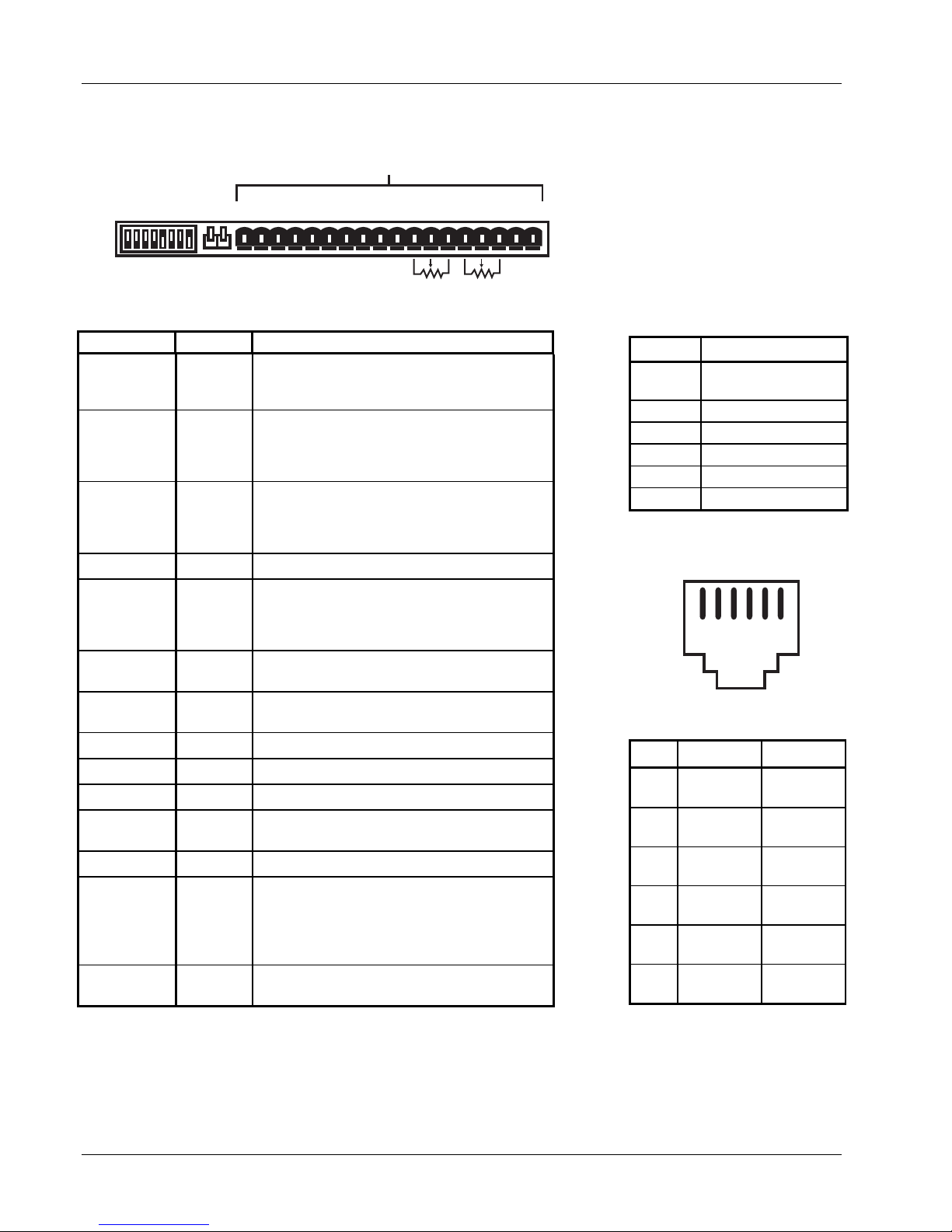
C
Lake Shore Model 620/622/623/647 Magnet Power Supply User’s Manual
5.5 REAR PANEL CONNECTOR DETAIL
Figure 5-1 MPS Rear Panel Connectors
MPS Rear Panel Connectors
RI FLT ON
MODE
INT
+ - + - + - OVP Im Vm m Vp +Vs -ls lp +ls -S +S
CAL AND ID V l
Active
Open
8 7 6 5 4 3 2 1
Table 5-1A Rear Panel Connector Definitions
TERMINAL LABEL DEFINITION
1
2
3
FLT +
4
5
6
7 Reserved
8
9 Im
10 Vm
11 m
12 Vp
13 +Vs
14 –Is
15 Ip
16
17
18
123456789101112131415161718
Vl
EXT
RI+
RI–
Remote Inhibit – Active low, TTL-compatible
input to remotely disable the output (force the
output settings to 0 A and 1 V).
Fault Indicator – Normally open contact closure
10K
to indicate a fault condition has occurred.
FLT–
Contact rating: 0.25 A resistive at 100 VDC, 3 W,
25 VA.
ON Indicator – Contact closure to indicate when
ON+
ON–
the front panel circuit breaker is in the ON
position. Contact rating: 0.25 A resistive at 100
VDC, 3 W, 25 VA.
None
Overvoltage Protection Enable – Analog signal
OVP
connected in parallel to other MPS Units to
remotely activate the output overvoltage
protection circuit.
Output Current Monitor – Voltage output from Im
to GND(M) is ±0.01 V/A.
Output voltage monitor – Voltage output from Vm
to GND(M) is ±0.01 V/V.
Monitor and program ground. GND(M).
Factory Use Only
Factory Use Only
Enable external output current programming via
MODE switch.
Voltage input from Ip to GND(M) is ±0.01 V/A.
A 10 kΩ potentiometer from +Is to –Is with center
tap to Ip produces the minimum voltage for full
+Is
scale current output (±1.25 V for Model 622 or
±1.55 V for Model 623). Voltage applied to Ip
sums with internal current programming voltage.
–S
+S
Remote voltage sense correction. Correction for
load lead drops of up to 0.5 V per lead.
10K
Table 5-1B Rear Panel
AL
AND ID Switch Definitions
Switch Function
1 - 3
LSB Multi-
Mainframe Address
4 Multi-Mainframe
5 Dither
6 Not Used
7 Inhibit Delay
8 Calibration
Figure 5-2 Serial
Interface Connector
123456
Table 5-2 Serial Interface
Connector Definition
PIN
1
2
3
4
5
6
RS-232C
FUNCTION
No
Function
Receive
Data
Signal
Ground
Signal
Ground
Transmit
Data
No
Connection
RS-485
FUNCTION
No
Connection
A
No
Connection
No
Connection
B
No
Connection
5-8
Error Messages & Troubleshooting
Page 67
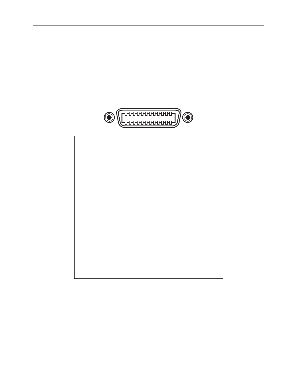
Lake Shore Model 620/622/623/647 Magnet Power Supply User’s Manual
5.6 IEEE-488 INTERFACE CONNECTOR (WHEN MODEL 6224 OPTION IS PRESENT)
Connect to rear MPS IEEE-488 Interface connector with cables specified in the IEEE-488-1978 standard
document. The cable has 24 conductors with an outer shield. The connectors at each end are 24-way
Amphenol 57 Series (or equivalent) with piggyback receptacles to daisy-chain multiple devices. Secure
connectors in the receptacles by a pair of captive locking screws with metric threads.
The total length of cable allowed in a system is 2 meters for each device on the bus, or 20 meters total for a
maximum of 15 devices. The figure below and the table to the right shows the IEEE-488 Interface connector
pin location and signal names.
SH1 AH1 T5 L4 SR1 RL1 PP0 DC1 DT0 C0 E1
121110987654321
24 23 22 21 20 19 18 17 16 15 14 13
PIN SYMBOL DESCRIPTION
1
2
3
4
5
6
7
8
9
10
11
12
13
14
15
16
17
18
19
20
21
22
23
24
DIO1
DIO2
DIO3
DIO4
EOI
DAV
NRFD
NDAC
IFC
SRQ
ATN
SHIELD
DIO5
DIO6
DIO7
DIO8
REN
GND 6
GND 7
GND 8
GND 9
GND 10
GND11
GND
Data Input/Output Line 1
Data Input/Output Line 2
Data Input/Output Line 3
Data Input/Output Line 4
End Or Identify
Data Valid
Not Ready For Data
Not Data Accepted
Interface Clear
Service Request
Attention
Cable Shield
Data Input/Output Line 5
Data Input/Output Line 6
Data Input/Output Line 7
Data Input/Output Line 8
Remote Enable
Ground Wire – Twisted pair with DAV
Ground Wire – Twisted pair with NRFD
Ground Wire – Twisted pair with NDAC
Ground Wire – Twisted pair with IFC
Ground Wire – Twisted pair with SRQ
Ground Wire – Twisted pair with ATN
Logic Ground
Figure 5-3. IEEE-488 Interface Connector
Error Messages & Troubleshooting
5-9
Page 68
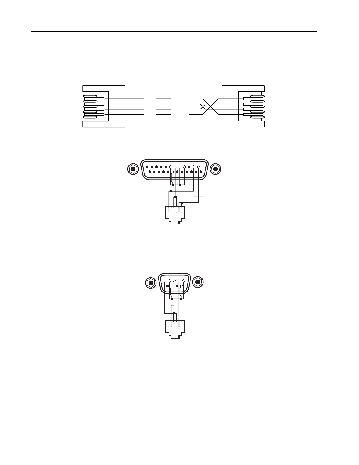
Lake Shore Model 620/622/623/647 Magnet Power Supply User’s Manual
5.7 SERIAL INTERFACE CABLE AND ADAPTERS
To aid in Serial Interface troubleshooting, the figures below provide wiring information for the cable assembly
and the two mating adapters.
6
345
12
C-MPS-5-4.eps
TxD
Gnd
Gnd
RxD
YELLOW
GREEN
RED
BLACK
12
3
4
56
Figure 5-4. Model 2001 RJ-11 Cable Assembly Wiring
13 12 11 10 9 8 7 6 5 4 3 2 1
25 24 23 22 21 20 19 18 17 16 15 14
DB-25
CONNECTOR
RxD
Gnd
TxD
123456
RJ-11
RECEPTACLE
Figure 5-5. Model 2002 RJ-11 to DB-25 Adapter Wiring
= Not Used
54321
9876
DB-9
CONNECTOR
RxD
Gnd
RJ-11
RECEPTACLE
TxD
123456
Figure 5-6. Model 2003 RJ-11 to DB-9 Adapter Wiring
5-10
Error Messages & Troubleshooting
Page 69

Lake Shore Model 620/622/623/647 Magnet Power Supply User’s Manual
CHAPTER 6
OPTIONS AND ACCESSORIES
6.0 GENERAL
This chapter covers MPS options and accessories: Model 6224 IEEE-488/Serial Interface installation
(Paragraph 6.1), Model 6226/6476 Liquid Helium Level and Gaussmeter Input Card (Paragraph 6.2), Model
6228 Persistent Switch Heater Output (Paragraph 6.3), Model 6228-2 Persistent Switch Heater Output
(Paragraph 6.4), and Accessories (Paragraph 6.5).
6.1 MODEL 6224 IEEE-488/SERIAL INTERFACE
This option interfaces with a Customer-supplied computer equipped with a compatible IEEE-488 or Serial
Interface. It accesses operating data and stored parameters and remotely controls front panel operations.
Only one Model 6224 is required for multiple MPS installations. See Chapter 4 for MPS remote operation.
Installation Procedure
WARNING
• This procedure is intended for trained service personnel who understand electronic circuitry and
the hazards involved. Do not attempt this procedure unless qualified.
• To prevent shock hazard, turn off the instrument and disconnect AC line power and all test
equipment before proceeding.
1. Turn unit OFF and disconnect power cord.
2. Remove the two screws of the blank option cover plate to the far left of the MPS rear panel and remove
the cover plate. If another option exists in this slot, remove it. The IEEE cable should point down. Install
the option in the far slot to avoid IEEE cable interference with the power cord.
3. Slide the Model 6224 board into the MPS with the board handle towards the bottom of the MPS. Tighten
the two screws that secure the board to the MPS rear panel.
4. (If Required) Install the option removed from the Model 6224 slot into a different slot.
5. Set the IEEE-488 operating parameters as outlined in Paragraph 4.1.1 and the Serial Interface as outlined
in Paragraph 4.2.2.
6.2 MODEL 6226/6476 LIQUID HELIUM LEVEL AND GAUSSMETER INPUT CARD
The Model 6226/6476 Liquid Helium Level and Gaussmeter Input Option combines liquid helium level and
field monitoring in one input card. It monitors liquid level in percent, inches, or centimeters, and field in
kilogauss or tesla. The field measurement is quantitative. Each input has independent excitation.
The level probe interfacing supports NbTi superconducting filaments and includes entry of probe length and
determination of probe resistance over the length. A unique level probe zero reference feature allows the user
to define the current liquid level reading as the “zero reference” and reads levels above or below that
reference. A software level alarm notifies the user when the continuously variable liquid level set point has
been reached.
When the liquid level measurement is not active, the field measurement is. The field interfacing supports Hall
sensors and includes probe zero and entry of probe sensitivity in millivolts per kilogauss.
The Model 6226 and Model 6476 have the same level circuitry. The Model 6226 Gaussmeter is designed to
operate with Hall sensors requiring 100 mA of excitation current. The Model 6476 Gaussmeter is designed to
operate with high sensitivity Hall sensors requiring 1 mA or excitation current. Cards identified by a 1996
copyright containing 6XX6.S firmware are field-configurable to either model.
Options & Accessories
6-1
Page 70

Lake Shore Model 620/622/623/647 Magnet Power Supply User’s Manual
Below are specifications for the Model 6226/6476 Liquid Helium Level and Gaussmeter Input Card:
Liquid Helium Level:
Probe Type: NbTi Superconducting Filament Sample Period: Fixed at 5 seconds
Number of Inputs: 1 four lead measurement Maximum Resistance: 428
Ω
Nominal Excitation Current: 70 mA Display Resolution: 1%, 0.1 inch, 0.1 cm
Compliance: 30 V Electronic Accuracy: 1% of full scale
Input Voltage Resolution: > 1 mV out of 30 volts full scale
Sample Interval: 1 min to 24 hours, continuous, or read on demand
Model 6226 Gaussmeter:
Cryogenic Hall Sensor Type: Lake Shore Model HGCT-3020 (transverse) or Model HGCA-3020 (axial)
Number of Inputs: 1 four lead measurement Display Resolution: 0.01 kG, 0.001 tesla
Nominal Excitation Current: 100 mA Electronic Accuracy: 1% of full scale
Probe Magnetic Sensitivity: 0.8 mV/kG ±30%
Nominal Field Range: Nominal ±125 kG (@ 0.8 mV/kG)
Input Voltage Resolution: > 0.01 mV out of 0.1 volts full scale
Sample Interval: Probe excited continuously & read when level is not
Model 6476 Gaussmeter:
Cryogenic Hall Sensor Type: Lake Shore Model MST-410 (transverse) or Model MSA-410 (axial)
Number of Inputs: 1 four lead measurement
Nominal Excitation: 1 mA
Probe Magnetic Sensitivity: 20 mV/mG
Nominal Field Range: Nominal
± 20 kG (@ 20 mV/kG)
±50%
Input Voltage Resolution: > 0.04 mV out of 0.4 volts full scale
Sample Interval: Probe excited continuously & read when level is not
Display Resolution: 0.01 kG (0.001T)
Electronic Accuracy: 1% of full scale
Contact Lake Shore for details on a variety of Hall Probes and Sensors.
6.2.1 Hall Sensor Mounting Considerations - Models HGCT-3020 and HGCA-3020
The Lake Shore Model HGCT-3020 (Transverse) and Model HGCA-3020 (Axial) Cryogenic Hall Sensors are
four terminal, solid state devices that produce output voltage proportional to the product of the input current,
magnetic flux density, and the sine of the angle between the field vector and the plane of the Hall generator.
The active area of the Model HGCT-3020 Transverse Hall Sensor is approximately 0.04 inch in diameter with
the center indicated by a cross on one face of the package. When the control current is applied with the red
lead positive with respect to the black lead, and the magnetic field is perpendicular into the face of the probe
with the cross on it, the Hall voltage is positive at the blue lead with respect to the yellow lead. A reversal in the
mechanical orientation or in the direction of either the magnetic field or the control current results in a polarity
change of the output voltage.
The active area of the Model HGCA-3020 Axial Hall Sensor is approximately 0.03 inch in diameter in the
center of the face opposite the leads. W hen the control current is applied with the red lead positive with
respect to the black lead, and the magnetic field is perpendicular into the face of the probe opposite the leads,
the Hall voltage is positive at the blue lead with respect to the yellow lead. Again, a reversal in mechanical
orientation or in the direction of either the magnetic field or control current results in a output voltage polarity
change.
Handle the Hall sensor with care. The ceramic substrate is brittle and very sensitive to bending stress. Mount
the sensor to minimize mechanical strains as the sensor cools. Failure rates approaching 10% occur on initial
cool down with improperly installed sensors (sensors surviving initial cool down generally experience no
problems on subsequent cycles). Avoid applying tension to the leads. Bend the leads at any angle so long as
the bend is at least 0.125 inch away from the substrate connection. Mount the device to a non-flexible, smooth
surface with a coefficient of thermal expansion no greater than a factor of three different from that of the
ceramic substrate (about 7 x 10
-6
in/in per K).
6-2
Options & Accessories
Page 71
Lake Shore Model 620/622/623/647 Magnet Power Supply User’s Manual
Locate the probe in a cavity that is 0.003 inch wider and 0.01 inch longer than the substrate, and with a depth
the same or slightly greater than the thickness of the package. Tack the leads outside the slot with GE-7031
varnish or other similar substance. Sparingly apply the mounting substance to the corners or a dot on each
side of the sensor to hold it in place. Avoid applying mounting substance on top of the sensor. Alternately, use
Kapton
apply only light pressure to the sensor. If epoxy is the mounting substance, use it sparingly and use the same
type as is used in the sensor, Stycast
®
tape or a mechanical cover over the top of the sensor to keep it in place. The tape or cover should
®
2850-FT epoxy. Never pot the probe.
A room temperature calibration over the range of ±30 kG comes with each probe. The calibration specifies the
terminating resistor (not included) required to maintain an accuracy of ±1% of reading up to ±30 kG and ±2%
of reading up to ±150 kG over the entire temperature range. For a terminating resistor, use a metal film
resistor with 1% or better accuracy mounted across the output voltage leads as close to the probe as is
practical. To extend the leads, use AW G 34 stranded copper with Teflon insulation (the same wire used on the
probe). Any impedance in the output leads acts as a voltage divider with the terminating resistor. Probe
reading reproducibility is within ±1% over repeated thermal cycling between 4.2 K and room temperature.
6.2.2 The Model MSA-410 and MST-410 Hall Sensors
Models MSA-410 and MST-410 gaussmeter probes are used with the Model 6476. Lake Shore offers a tenfoot extension cable (Model MPEC-410-10).
6.2.3 Connections
The Model 6226/6476 has one rear panel 9-pin connector to interface with the
level and field probes. See Table 6-1.
6.2.4 Installation
The 6226/6476 Liquid Helium Level and Gaussmeter Input Option is factoryinstalled if ordered with a MPS or may be field installed at a later date. For
field installation, use the procedure below:
WARNING
• This procedure is intended for trained service personnel who
understand electronic circuitry and the hazards involved. Do not
attempt this procedure unless qualified.
• To prevent shock hazard, turn off the instrument and disconnect AC
Table 6-1 Model 6226/6476
Connections
Terminal Description
1
2
3
4
5
6
7
8
9
Field –Current
Field –Voltage
Field +Voltage
Field +Current
Shield
Level –Current
Level –Voltage
Level +Voltage
Level +Current
line power and all test equipment before removing cover.
1. Turn off the MPS and disconnect the power cord.
2. Locate the Optional Plug-In Board Slots on the MPS rear panel. Loosen the two screws that secure one of
the blank cover plates and remove the cover plate.
3. Slide the Model 6226/6476 board into the MPS with the board handle towards the bottom of the MPS.
Tighten the two screws that secure the board to the MPS rear panel.
Options & Accessories
6-3
Page 72
Lake Shore Model 620/622/623/647 Magnet Power Supply User’s Manual
6.2.5 LHe Level
Access liquid helium level and field monitoring from
the MPS front panel. Press Function Menu and
then Next Menu to display Function Menu 2. If the
Model 6226/6476 Option is not present, <NP>
appears next to LHe LEVEL and FIELD and
associated function keys are ignored.
OUTPUTS ONLY
LHe LEVEL
FIELD
PSH SETUP
2/3
6.2.5.1 LHe Level Operation
Press the LHe LEVEL Function key to display the
Liquid Helium Level screen. The Menu window
returns to display Output values.
The cursor up and down keys move the line
indicator. The
¥ icon indicates parameters changed
only with the Data Entry up and down arrows. When
LIQUID HELIUM LEVEL:
¤READING
UNITS
NEXT RDG
PERIOD
ALARM
ZERO REF
CALIBRATE SENSOR
: <OFF>
: in (E)
: 00:16
: 01:00
:+ 14.5 <ON>
:+ 0.0<OFF>
¥
¥
¥
¥
¥
OUTPUTS: *
+1.999A
+0.001V
LVL: +14.4 in
FLD: +63.48 kG
there are <ON> or <OFF> indicators, the Data Entry
up and down arrows change the status if they are the first data entry keys used.
READING: <OFF> or <ON>
Level Reading Status. The Data Entry up or down arrow initiates a level reading.
UNITS: in. (E), %, or cm (M)
Level Units. The Data Entry up or down arrow scrolls through the available units: inches (English), %
(percent), or centimeters (Metric).
NEXT RDG: 00:00 (Time in Hours:Minutes)
The Time to Next Reading.
PERIOD: 00:00 (Time in Hours:Minutes)
Level Sample Period. A time of 00:00 indicates a continuous reading (20 second period, 5 seconds for level
reading). Use any numeric entry mode to change the value. Period limit is 23:59.
ALARM: + 0.0 (Reading) and <OFF> or <ON>
Level Alarm and Alarm Status. The Data Entry up or down arrow toggles the status. Use any numeric entry
mode to change the value.
ZERO REF: + 0.0 (Reading) and <OFF> or <ON>
Level Zero Reference Value and Status. The Data Entry up or down arrow toggles the status. When ON, the
value entered is the zero reference reading which the software subtracts from the actual level reading to give a
“relative” level reading. Use any numeric entry mode to change the value.
CALIBRATE SENSOR
Change level sensor length, units, and calibration from this screen. The Data Entry up or down arrow displays
the Level Calibration screen.
If the level alarm is on and the MPS detects that the
level alarm has been reached, the MPS closes the
FLT contacts to indicate the fault, sounds an alarm
about once per second, and displays the screen to
the right. The alarm continues to sound until the
level alarm is turned off. When the alarm is turned
off (or disabled), the MPS opens the FLT contacts
and turns off the alarm.
6-4
Options & Accessories
LIQUID HELIUM LEVEL:
¤READING
UNITS
NEXT RDG
PERIOD
ALARM
ZERO REF
CALIBRATE SENSOR
: <OFF>
: in (E)
: 00:16
: 01:00
:+ 14.5 <ON>
:+ 0.0<OFF>
¥
¥
¥
¥
¥
OUTPUTS: *
+1.999A
+0.001V
LVL: +14.4 in
FLD: +63.48 kG
**LEVEL ALARM**
Page 73

Lake Shore Model 620/622/623/647 Magnet Power Supply User’s Manual
6.2.5.2 Field Probe Setting and Calibration
Press Function Menu and then Next Menu to
display Function Menu 2. Press the FIELD Function
key to display the Field screen to the right.
FIELD PROBE SETTING:
UNITS: T or kG
FIELD PROBE SETTING:
¤UNITS
CALIBRATE PROBE
mV/kG
ZERO RDG
: kG ¥
: + 0.800
:¥TO CALIBRATE
OUTPUTS: *
+1.999A
+0.001V
LVL: +14.4 in
FLD: +0.501 kG
Field Units. The Data Entry up or down arrows scroll
between the units: T (tesla) or kG (kilogauss). The default is kG.
CALIBRATE PROBE:
NOTE: The entries below change probe calibration. Do not change unless probe is actually being calibrated.
mV/kG: +XXX.XXX
Field Probe Sensitivity. Each Hall Probe comes with a mV/kG sensitivity. Use any numeric entry mode to
change the value from 0 to 999.999.
ZERO RDG: <OFF> or <ON>
Field Probe Zero Reading. Connect the Hall Probe and place it in zero magnetic field. Press a Data Entry up
or down arrow key to zero the probe.
6.2.6 Level Sensor Calibration
To enter or measure level sensor parameters,
select CALIBRATE SENSOR (line 8) in the LIQUID
HELIUM LEVEL screen. Prior to this, select a length
of inches or centimeters (not percent). Units of
length do not display on the calibration screen if
LEVEL SENSOR CONSTANTS:
¤LENGTH
MIN ¦
¦/inch
SELF CALIBRATION:
CALIBRATE MIN ¦
CALIBRATE ¦/inch
: 24.0 in
: 0.00
: 10.41
¥
¥
OUTPUTS: *
+0.000A
+0.000V
LVL: +14.4 in
FLD: +0.501 kG
percent is selected.
LENGTH: 24.0 in or LENGTH: 61.0 cm
Level Sensor Length. Use any numeric entry mode to change the value. Allows values from 0.0 to 999.9.
MIN
ΩΩΩΩ: 0.00 (ohms)
Level Sensor minimum resistance in ohms. If minimum resistance is known, enter it directly with the Data
Entry keys. Otherwise, measure it as shown below under SELF CALIBRATION: CALIBRATE MIN
ΩΩΩΩ.
ΩΩΩΩ /inch: 10.41 or ΩΩΩΩ /cm : 4.10
Level Sensor resistance per unit length. If the value is known, enter it directly with the Data Entry keys.
Otherwise, it can be measured as shown below under SELF CALIBRATION: CALIBRATE
CALIBRATE MIN
ΩΩΩΩ ¥
¥
¥¥
Ω/inch(cm).
Measures the Level Sensor minimum resistance. Connect the level sensor immersed in LHe to the active level
sensor length. Move the cursor to CALIBRATE MIN
the display changes to CALIBRATING MIN
ΩΩΩΩ…. After measurement, the display updates the minimum
ΩΩΩΩ and press a Data Entry up/down arrow key. That line of
resistance in line 3 and the display returns to that shown above.
CALIBRATE
ΩΩΩΩ/inch ¥
¥ or CALIBRATE Ω
¥¥
Ω/cm ¥
ΩΩ
¥
¥¥
Measures the Level Sensor resistance per unit length. The resistance per unit length is a function of
temperature. The effective value can be determined from the value measured at a more convenient
temperature. Figure 6-1 and Table 6-2 show the resistance values as a function of temperature of a NbTi
filament. The procedure described below measures the resistance per unit length at room temperature.
Take the level sensor out of the liquid and allow its temperature to stabilize. Move the cursor to CALIBRATE
ΩΩΩΩ/inch and press a Data Entry up/down arrow key. That line of the display changes to CALIBRATING
ΩΩΩΩ/inch(cm)…. After measurement, the display updates the Ω/inch (Ω/cm) in line 4 and the display returns to
that shown above.
NOTE: If the resistance is too large, the value is not updated. In that case, use a lower temperature or an
ohmmeter to measure the resistance.
Options & Accessories
6-5
Page 74
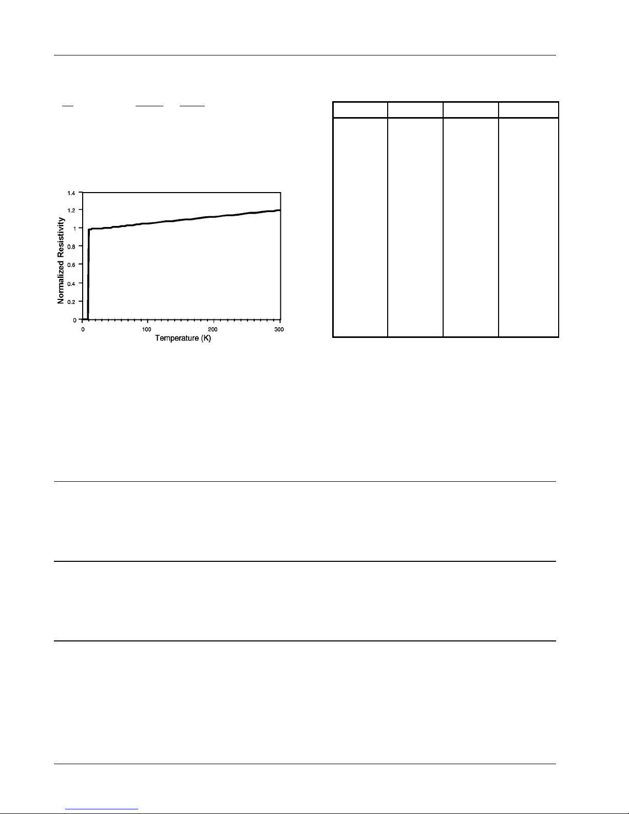
Look up the R
Ω
F
I
effective
G
J
H
K
L
where L
computed value in line 4 manually.
Figure 6-1. NbTi Filament Resistance Chart
REF/R(T)
is the sensor length (line 2). Enter the
active
Lake Shore Model 620/622/623/647 Magnet Power Supply User’s Manual
in Table 6-2 at the temperature of the sensor during measurement. Use the equation:
L
R
T
bg
=×
L
active
O
R
REF
M
P
R
M
P
T
bg
N
Q
Table 6-2. NbTi Filament Resistance Values
Temp. (K) Temp. (°C) Temp. (°F) R ref/R (T)
305.15
300.15
299.15
298.15
297.15
296.15
295.15
294.15
293.15
292.15
291.15
290.15
273.15
80.00
77.35
75.00
22.00
20.00
15.00
10.00
32.00
27.00
26.00
25.00
24.00
23.00
22.00
21.00
20.00
19.00
18.00
17.00
0.00
–193.15
–195.80
–198.15
–251.15
–253.15
–258.15
–263.15
89.60
80.60
78.80
77.00
75.20
73.40
71.60
69.80
68.00
66.20
64.40
62.60
32.00
–315.67
–320.44
–324.67
–420.07
–423.67
–432.67
–441.67
0.8401
0.8424
0.8428
0.8433
0.8438
0.8442
0.8447
0.8452
0.8456
0.8461
0.8466
0.8470
0.8550
0.9613
0.9630
0.9646
0.9973
0.9981
1.0000
1.0046
6.2.7 Model 6226/6476 IEEE-488 Remote Operation Commands
Cmd Function
BFLD? Magnetic Field Query
BUNI Program Field Units
BUNI? Field Units Query
IBS? Field Summary Query
LALM Program Level Alarm
LALM? Level Alarm Query
Cmd Function
LALMS Program Level Alarm Status
LALMS? Level Alarm Status Query
LEVL Read Level
LEVL? Level Query
LUNI Program Level Units
LUNI? Level Units Query
Cmd Function
PER Program Sample Period
PER? Sample Period Query
ZREF Program Probe Zero Reference
ZREF? Probe Zero Reference Query
ZREFS Program Zero Reference Status
ZREFS? Zero Reference Status Query
BFLD? Magnetic Field Query
Input: BFLD?
Returned: A number between ±999.9999.
Remarks: Returns nine characters plus up to two terminators.
BUNI Program Magnetic Field Units
Input: BUNI [units] where [units] = kG for kilogauss, or T for tesla (10 kilogauss).
Remarks: The initial status is kG. Verify there is a space between the command and the units
parameter.
BUNI? Magnetic Field Units Query
Input: BUNI?
Returned: Either kG for kilogauss or T for tesla (10 kilogauss).
Remarks: Returns two characters plus up to two terminators.
6-6
Options & Accessories
Page 75

Lake Shore Model 620/622/623/647 Magnet Power Supply User’s Manual
IBS? Magnetic Field Summary Query
Input: IBS?
Returned: [IOUT], [BFLD], [STB]
Remarks: Returns 23 characters plus up to two terminators.
LALM Program Level Alarm
Input: LALM [alarm] where [alarm] is the level value between 0 and ±999.9 that activates the
alarm. The value is truncated (not rounded) to the tenths place.
Remarks: The initial condition is 0. The alarm value uses the existing units. Conversion is made if units
are changed.
LALM? Level Alarm Query
Input: LALM?
Returned: The value returned is a number between ±999.9000.
Remarks: Nine characters plus up to two terminators are returned.
LALMS Program Level Alarm Status
Input: LALMS [status] where [status] = 0 for OFF, or 1 for ON.
Remarks: The initial condition is 0.
LALMS? Level Alarm Status Query
Input: LALMS?
Returned: 0 or 1. 0 indicates that the level alarm has not been reached. 1 indicates that the level is
below the alarm value and the alarm has been activated.
Remarks: Returns one character plus up to two terminators.
LEVL Read LHe Level
Input: LEVL [status] where [status] = 1 to read the level, or 0 not to read it.
Remarks: Reading the level requires a minimum of 5 seconds to update the level reading.
LEVL? LHe Level Query
Input: LEVL?
Returned: A number between ±999.9000.
Remarks: Returns nine digits plus up to two terminators.
LUNI Program LHe Level Units
Input: LUNI [units] where [units] = "%" for percentage, "E" for English units (inches), or "M" for
metric units (centimeters).
Remarks: The initial condition is E (inches). Make sure there is a space between the command and the
units parameter.
Options & Accessories
6-7
Page 76

Lake Shore Model 620/622/623/647 Magnet Power Supply User’s Manual
LUNI? LHe Level Units Query
Input: LUNI?
Returned: % for percentage, E for English units (inches), or M for metric units (centimeters)
Remarks: Returns one character plus up to two terminators are returned.
PER Program Sample Period
Input: PER [hours]:[minutes] where [hours] = 0 to 23, and [minutes] = 0 to 59.
Remarks: Programs the sample period in hours and minutes. The initial condition is 00:00, which
defines a continuous sample period. Max. time is 23 hours, 59 seconds.
PER? Sample Period Query
Input: PER?
Returned: Hours and minutes programmed for the sample period, a comma, then the hours and minutes
left in the sample period. Example - 23:59,10:10[term]. Indicates an initial sample period
program of 23 hours and 59 minutes with 10 hours and 10 minutes remaining.
Remarks: Returns eleven characters plus up to two terminators.
ZREF Programs the probe zero reference
Input: ZREF [zero reference] where [zero reference] = a value between 0 and ±999.9 truncated
(not rounded) to the tenths place.
Remarks: The initial condition is 0. The zero reference uses the existing units. Conversion is made if
units are changed.
ZREF? Probe Zero Reference Query
Input: ZREF?
Returned: A number between ±999.9000.
Remarks: Returns nine characters plus up to two terminators.
ZREFS Program Probe Zero Reference Status
Input: ZREFS [status] where [status] = 1 to add the zero reference value to the level reading, or 0
to return the level reading to absolute.
Remarks: Programs the probe zero reference status. The initial condition is 0. The level read above the
zero reference is positive while the level read below the zero reference is negative.
ZREFS? Zero Reference Status Query
Input: ZREFS?
Returned: 0 if the probe zero reference status is disabled, or 1 if it is enabled.
Remarks: Returns one character plus up to two terminators.
6-8
Options & Accessories
Page 77
Lake Shore Model 620/622/623/647 Magnet Power Supply User’s Manual
6.3 MODEL 6228 AND 6228-8MUX PERSISTENT SWITCH HEATER OUTPUT
The Model 6228 Persistent Switch Heater (PSH) Output Option provides a variable 0-124 mA DC output in 4
mA increments. The output compliance is an 8 volt minimum and the load can be up to 100 ohms. An MPS
front panel annunciator indicates PSH output current status. Model 6228 specifications are as follows:
Output Range: 0 to +124 mA Load: 100 ohms maximum
Output Resolution: 4 mA Off State Leakage Current: Less than 1 mA
Output Compliance: 8V minimum (8.7 typical at 124 mA)
The Model 6228 output current is present on a detachable terminal block with the I+ output on the terminal
towards the top of the board (1) and the I- terminal towards the bottom of the board (2).
6.3.1 Installation
WARNING
• This procedure is intended for trained service personnel who understand electronic circuitry and
the hazards involved. Do not attempt this procedure unless qualified.
• To prevent shock hazard, turn off the instrument and disconnect AC line power and all test
equipment before removing cover.
NOTE: With multiple MPS units, install the Model 6228 in MPS1 for proper operation.
The 6228 is factory-installed if ordered with a MPS or can be field installed at a later date. For field installation,
use the following procedure.
1. Turn off the MPS and disconnect the power
cord.
2. Locate the Optional Plug-In Board Slots on the
MPS rear panel. Remove the two screws that
secure a blank cover plate to the MPS rear
panel and remove the cover plate.
CAUTION! SETTING NOT SAME AS SAVED VALUE
LAST PERSISTENCE CURRENT :
PRESENT SUPPLY CURRENT :
ENTER KEY TO CHANGE TO LAST PERSISTENCE
CURRENT, WAIT RUNUP DELAY, THEN TURN OFF.
¥ KEY TO TURN OFF AT PRESENT CURRENT.
Esc KEY TO ABORT.
HEATER CURRENT: 50 mA
10.000 A
5.000 A
3. Slide the Model 6228 board into the MPS with the board handle towards the bottom of the MPS. Tighten
the two screws that secure the board to the MPS rear panel.
6.3.2 Model 6228 Operation
Access PSH Control from the MPS front panel.
Press Function Menu then Next Menu to display
Function Menu 2. If the 6228 PSH Option is not
present, <NP> appears next to PSH SETUP and the
associated function key is ignored.
Press the PSH SETUP function key to enter the
OUTPUTS ONLY
LHe LEVEL
FIELD
PSH SETUP
2/3
PSH Screen.
The cursor up and down keys move the line indicator (
→). The ¥ icon indicates parameters changed only with
the Data Entry up and down arrows. Change all others using all the numeric entry modes, including the cursor.
HEATER: XXX mA
PSH Heater Current. Use any numeric entry mode
to change the value from 0 to 999 mA.
PERSISTENCE HTR SETUP:
¤HEATER
STATUS
LAST END
: 50 mA
: <HTR ON>
: + 0.000A
OUTPUTS: *
+2.000A
+0.000V
STATUS: <OFF> or <ON>
PSH Status. Use the Data Entry up or down arrows
to toggle the status.
LAST END: + 0.000 A
Last Current Setting. This value is the current setting when the PSH was turned off. This value is retained in
non-volatile memory so that the output current can be set to the magnet current when the PSH is turned on.
Options & Accessories
6-9
Page 78
Lake Shore Model 620/622/623/647 Magnet Power Supply User’s Manual
When PSH is ON, the MPS compares the present
current setting with the current setting stored when
PSH was OFF. If the two do not match, the MPS
sounds the alarm for ½ second and displays:
Press a Data Entry up or down arrow to turn ON the
PSH. If Esc is pressed, or no key is pressed for
approximately 30 seconds, the PSH is not turned
ON.
6.3.3 Model 6228-8MUX Operation
The 6226-8MUX is a persistence card with a
multiplexed output. The output specifications are the
same as the single 6228 option card. The heater
supply current connects to one of eight persistence
heaters. The PSH SETUP screen displays an
additional line indicating the channel active if the
heater is turned on. To change channels, access
the PSH SETUP screen, move the cursor to the
CHANNEL line, and use the Data Entry up and
down arrows to increment to the desired channel.
Select Channel 0 to force the heater off.
If the heater is on and connected to a channel,
changing channels may cause problems. A warning
displays to prevent a mishap.
The Normal Manual screen shows which channel
connects to the heater when the heater turns on
(persistence off). W hen a zero displays, the heater
is off and not connected to any of the multiplexed
outputs. When a 1 through 8 displays, then that
multiplexed channel is controlled.
CAUTION! SETTING NOT SAME AS SAVED VALUE
LAST PERSISTENCE CURRENT :
PRESENT SUPPLY CURRENT :
ENTER KEY TO CHANGE TO LAST PERSISTENCE
CURRENT, WAIT RUNUP DELAY, THEN TURN OFF.
¥ KEY TO TURN OFF AT PRESENT CURRENT.
Esc KEY TO ABORT.
PERSISTENCE HTR SETUP:
¤HEATER
STATUS
LAST END
CHANNEL
PERSISTENCE HTR SETUP:
¤HEATER
STATUS
LAST END
THE HEATER IS ON.
CANNOT CHANGE CHANNEL
WITH THE HEATER ON.
Esc TO CONTINUE.
SETTINGS:
+2.000A
COMPLIANCE
RAMP RATE
RAMP ENABLE
¤CH 1,PERS.
HEATER CURRENT: 50 mA
: 50 mA
: <HTR ON>
: + 0.000A
: 1 ¥ +0.000V
: 50 mA
: <HTR ON>
: + 0.000A
OUTPUTS: *
+2.000A
OUTPUTS: *
+2.000A
OUTPUTS: *
10.000 A
5.000 A
+0.000V
+2.000A
:+ 5.000V
:+ 1.000A/S
: <OFF> ¥
: <ON> ¥
+1.000V
The magnet is put in and taken out of persistence via the last line on the Normal Manual Screen as with the
6228 PSH card. To change the channel number, access the Normal Manual Screen, use the Right/Left Cursor
to move to the channel number, and then use the numerical keypad entry keys. The data Entry up or down
arrow toggles the persistence on and off.
The Automatic Mode shown to the right allows
channel selection on line 7 prior to running the
Automatic change of persistence current.
To change the channel number on the Automatic
Screen, use the Right/Left Cursor to move to the
channel number, and then use the numerical
AUTOMATIC MODE:
¤MGT START
MGT END
MGT RATE
PERS RATE
LAST END
CH 1,PERS.
RUN ¥
: 10.000A
: 15.000A
: 1.000A/S
: 1.000A/S
: 10.000A
: <ON>
OUTPUTS: *
+0.000A
+0.001V
STANDBY
keypad entry keys. The Data Entry up or down arrow
not toggle persistence on and off. Persistence toggles on and off automatically.
does
6.3.4 PSH Card Voltage Constraints
The PSH (Persistence Switch Heater) card of the MPS supplies a current to a resistance heating element to
"normal" a persistence wire opening the ends of a supercooled magnet to enable charge (current) change.
Program current from 0 to 124 mA through the PSH Setup screen. Three conditions must be met when
selecting an appropriate current:
1. The current must be enough to "normal" the switch element. The magnet manufacturer specifies this
current and the heater resistance. This current must fall between the two following extremes.
2. The selected current multiplied by the heater resistance (e = i
× r) must be greater than 0.65 Vdc for the
MPS to accurately determine switch status when heated. If less than 0.65 Vdc, the MPS may not properly
report switch mode.
6-10
Options & Accessories
Page 79

3. The selected current multiplied by the heater resistance (e = i × r) must be less than 15 Vdc for the MPS
to accurately determine compliance of the switch heater (open resistance).
Examples: A 100 ohm heater resistance set for 100 mA yields 10 volt compliance (Ohm's Law). This is
greater than the required 0.75 Vdc and yet less than 15 Vdc. This allows proper performance. A 10 ohm
heater resistance set for 50 mA yields 0.5 Vdc – less than the minimium for acceptable operation. The MPS
cannot reliably determine the switch status and may report erroneously in some conditions. The best solution
is to raise the current to 100 mA or greater while meeting all conditions.
6.3.5 Model 6228 Remote Operation Commands
Lake Shore Model 620/622/623/647 Magnet Power Supply User’s Manual
IPSH Program PSH Current
Input: IPSH [current] where [current] = a value from 0 to 125 mA
Remarks: The initial condition is 0 mA. Current can be set from 0 to 125 mA but will actually be set in
4 mA increments.
IPSH? PSH Current Query
Input: IPSH?
Returned: A number between 0 and 125.
Remarks: Returns three characters plus up to two terminators.
PSH Program PSH Heater Status
Input: PSH [status] where [status] = 0 to turn off the persistent switch heater, or 1 to turn on the
persistent switch heater. Heater ON means persistence is OFF.
PSH? PSH Heater Status Query
Input: PSH?
Returned: 0 if the heater is OFF, or 1 if the heater is ON. If a current setting of 0 is entered, the value
returned is 0. Heater ON means persistence is OFF.
Remarks: Returns one character plus up to two terminators.
PSHC? PSH Compliance Status Query
Input: PSHC?
Returned: 0 if PSH output is under the output compliance limit, or 1 if the output is over the limit.
Remarks: Returns one character plus up to two terminators.
PSHIS? Current Setting When PSH Was Turned Off
Input: PSHIS?
Returned: The value returned is a number between ±125.0000 A.
Remarks: Returns nine characters plus up to two terminators.
Options & Accessories
6-11
Page 80

Lake Shore Model 620/622/623/647 Magnet Power Supply User’s Manual
PSHS? PSH Summary Query
Input: PSHS?
Returned: [PSH][PSH status][PSH compliance][current value][command status] where:
[PSH] = 0 if PSH is present, or 1 if PSH is not present,
[PSH heater status] = 0 if heater is OFF, or 1 if it is ON,
[PSH compliance] = 0 if PSH is under compliance or 1 if it is over.
[current value] = up to three characters which give the current value
[command status] = 0 if the command status is OFF, or 1 if it is ON.
Remarks: Returns seven characters plus up to two terminators.
PSHCH Program PSH Channel (Multiplex PSH Card ONLY)
Input: PSHCH [channel], where [channel] = 0 to 8
Returned: Nothing.
Remarks: Command applies to the Model 6228-8MUX Card ONLY. 0 = heater OFF; 1 to 8 = heater ON.
PSHCH? PSH Channel Query (Multiplex PSH Card ONLY)
Input: PSHCH?
Returned: Channel number from 0 to 8
Remarks: Command applies to the Model 6228-8MUX Card ONLY. 0 = heater OFF; 1 to 8 = heater ON.
Returns one character plus up to two terminators.
6.4 MODEL 6228-2 PERSISTENT SWITCH HEATER OUTPUT
The Model 6228-2 Persistent Switch Heater Output Option controls a second Persistent Switch. The output
has the same specifications as the 6228 card.
The PSH SETUP screen using a 6228 and a 6228-2 card appears to the right. Only the heater currents can be
changed on this screen. The status of the heater is either on or off. The last value is the current of the power
supply when the heater was last turned off.
The PSH SETUP screen using a 6228-8MUX and a
6228-2 card appears to the right. Note that the
Channel displays for the 6228-8MUX card. The
heater currents and channel of the 6228-8MUX can
be changed on this screen. The status of the heater
is either on or off. The last value LAST 1 is the
PERSISTENCE HTR SETUP:
¤HEATER 1
STATUS 1
LAST 1
CHANNEL
HEATER 2
STATUS 2
LAST 2
: 50 mA
: <HTR ON>
: + 0.000A
: 1 ¥
: 50 mA
: <HTR ON>
: + 0.000A
OUTPUTS: *
+2.000A
+0.000V
current of the power supply when the heater was
last turned off for the given channel of the 6228-8MUX.
The PSH SETUP screen using ONLY a 6228-2 card
appears to the right.
PERSISTENCE HTR2 SETUP: OUTPUTS: *
+2.000A
¤HEATER 2
STATUS 2
LAST 2
: 50 mA
: <HTR ON>
: + 0.000A
+0.000V
6-12
Options & Accessories
Page 81

6.4.1 Model 6228-2 Remote Operation Commands
Lake Shore Model 620/622/623/647 Magnet Power Supply User’s Manual
IPSHB Program PSH Current
Input: IPSHB [current] where [current] = a value from 0 to 125 mA
Remarks: The initial condition is 0 mA. Current can be set from 0 to 125 mA but will actually be set in 4
mA increments.
IPSHB? PSH Current Query
Input: IPSHB?
Returned: A number between 0 and 125.
Remarks: Returns three characters plus up to two terminators.
PSHB Program PSH Heater Status
Input: PSHB [status] where [status] = 0 to turn OFF the persistent switch heater, or 1 to turn ON
the persistent switch heater. Heater ON means persistence is OFF.
PSHB? PSH Heater Status Query
Input: PSHB?
Returned: 0 if the heater is OFF, or 1 if the heater is ON. If a current setting of 0 is entered, the value
returned is 0. Heater ON means persistence is OFF.
Remarks: Returns one character plus up to two terminators.
PSHBC? PSH Compliance Status Query
Input: PSHBC?
Returned: 0 if PSH output is under the output compliance limit, or 1 if the output is over the limit.
Remarks: Returns one character plus up to two terminators.
PSHBIS? Current Setting When PSH Was Turned Off
Input: PSHBIS?
Returned: The value returned is a number between ±125.0000 A.
Remarks: Returns nine characters plus up to two terminators.
PSHBS? PSH Summary Query
Input: PSHBS?
Returned: [PSHB][PSHB status][PSHB compliance][current value][command status] where:
[PSHB] = 0 if PSH is present, or 1 if PSH is not present,
[PSHB heater status] = 0 if heater is OFF, or 1 if it is ON,
[PSHB compliance] = 0 if PSH is under compliance or 1 if it is over.
[current value] = up to three characters which give the current value
[command status] = 0 if the command status is OFF, or 1 if it is ON.
Remarks: Returns seven characters plus up to two terminators.
Options & Accessories
6-13
Page 82
Lake Shore Model 620/622/623/647 Magnet Power Supply User’s Manual
6.5 ACCESSORIES
Accessories are devices that perform a secondary duty as an aid or refinement to the primary unit. Below are
MPS accessories.
MODEL NUMBER DESCRIPTION OF ACCESSORY
106-720 Terminal Block Mate, 18-Contact.
106-726 Detachable Power Connector.
106-730 Terminal Block Mate, 4 contact.
115-010 Detachable 240 VAC Line Cord (Great Britain).
115-011 Detachable 120 VAC Line Cord (USA, Canada).
115-012 Detachable 220 VAC Line Cord (Europe, SA).
2001
2002
2003
RJ-11 Cable Assembly. Four-Wire Cable Assembly with RJ-11 plugs on each end. Used
with RS-232C Interface. Cable is 14 feet (4.6 meters) long. See Figure 5-4.
RJ-11 to DB-25 Adapter. Adapts RJ-11 receptacle to female DB-25 connector. Used to
connect Model 622/623 to Serial Port on rear of Customer’s computer. See Figure 5-5.
RJ-11 to DE-9 Adapter. Adapts RJ-11 receptacle to female DE-9 connector. Used to
connect Model 622/623 to Serial Port on rear of Customer’s computer. See Figure 5-6.
6007 Serial Optical Isolation Link.
8072 IEEE-488 Interface Cable. Cable is 3.4 feet (1 meter) in length.
MAN-623 Model 622/623 User’s Manual.
MST-410
MSA-410
Transverse Probe. Used in electromagnetic fields. This probe is the same as used with the
Lake Shore Model 410 Gaussmeter.
Axial Probe. Used in electromagnetic fields. This probe is the same as used with the Lake
Shore Model 410 Gaussmeter.
MPEC-410-3 Extension Cable. Used with the Model MST-410 and MSA-410 listed above.
Hall Sensor, Magnetic Field, Cryogenic, Transverse. This is an individual transverse Hall
HGCT-3020
sensor meant for use in cryogenic magnet applications. Refer to Paragraph 6.2.1. for
mounting considerations.
Hall Sensor, Magnetic Field, Cryogenic, Axial. This is an individual axial Hall sensor
HGCA-3020
meant for use in cryogenic magnet applications. Refer to Paragraph 6.2.1. for mounting
considerations.
MCT-3160-WN
MCA-2560-WN
Probe, Magnetic Field, Cryogenic, Transverse. This is a complete 60 inch long Probe
Assembly using a Model HGCT-3020 Transverse Hall Sensor.
Probe, Magnetic Field, Cryogenic, Axial. This is a complete 60 inch long Probe Assembly
using a Model HGCA-3020 Axial Hall Sensor.
— Output Cable Set. Output cables are 4 AWG. Each cable is 12 feet (3 meters) long.
6-14
Options & Accessories
Page 83
Lake Shore Model 620/622/623/647 Magnet Power Supply User’s Manual
APPENDIX A
UNITS FOR MAGNETIC PROPERTIES
Conversion from CGS to SI Units
Quantity Symbol
Magnetic flux density,
Magnetic induction
Magnetic Flux
Magnetic potential difference,
magnetomotive force
Magnetic field strength,
magnetizing force
(Volume) magnetizationg M emu/cm
(Volume) magnetization 4πM G 10
Magnetic polarization,
intensity of
magnetization
(Mass) magnetization
Magnetic moment
Magnetic dipole moment j emu, erg/G 4π x 10
(Volume) susceptibility
(Mass) susceptibility
(Molar) susceptibility
Permeability µ dimensionless 4π x 10
Relative permeabilityj µ
(Volume) energy
density, energy product
Demagnetization factor D, N dimensionless 1/4π dimensionless
NOTES:
a. Gaussian units and cgs emu are the same for magnetic properties. The defining relation is B = H + 4πM.
b. Multiply a number in Gaussian units by C to convert it to SI (e.g. 1 G x 10
c. SI (Système International d'Unités) has been adopted by the National Bureau of Standards. Where two conversion factors are given, the upper
one is recognized under, or consistent with, SI and is based on the definition B = µ
recognized under SI and is based on the definition B = µ
d. 1 gauss = 10
e. Both oersted and gauss are expressed as cm
f. A/m was often expressed as "ampere-turn per meter" when used for magnetic field strength.
g. Magnetic moment per unit volume.
h. The designation "emu" is not a unit.
i. Recognized uder SI, even thoug based on the definition B = µ
j. µ
= µ/µ0 = 1 + χ, all in SI. µr is equal to Gaussian µ.
r
k. B • H and µ
R.B. Goldfarb and F.R. Fickett, U.S. Department of Commerce, National Bureau of Standards, Bolder, Colorado 80303, March 1985, NBS Special
Publication 696. For sale by the Superintendent of Documents, U.S. Government Printing Office, Washington, D.C. 20402.
5
M • H have SI units J/m3, M • H and B • H/4π have Gaussian units erg/cm3.
0
gamma (γ).
k
B gauss (G)d 10-4
φ maxwell (Mx), G•cm2 10-8
U, F gilbert (Gb) 10/4π
H oersted (Oe),e Gb/cm 103/4π A/mf
J, I emu/cm3 4π x 10-4 T, Wb/m2i
σ, M emu/g
m emu, erg/G 10-3
χ, κ
χρ, κρ cm3/g, emu/g
χ
, κ
mol
cm3/mol, emu/mol
mol
not defined - dimensionless
r
W erg/cm3 10-1 J/m3
-½
•g½•s-1 in terms of base units.
Gaussian
& CGS emua
3h
103 A/m
dimensionless
emu/cm3
-4
T/G = 10-4T).
H + J, where the symbol I is often used in place of J.
0
H + J. See footnote c.
0
Conversion
Factor, Cb
Rationalized mksc
SI &
tesla (T), Wb/m
weber (Wb), volt
second (V•s)
ampere (A)
3
/4π A/m
2
1
4π x 10
-7
A•m
/kg
Wb•m/kg
A•m2, joule per
-10
Wb•mi
-
(4π)2 x 10⁻⁷
4π x 10-3
(4π)2 x 10
4π x 10-6
(4π)2 x 10
(H + M), where to µ0 = 4π x 10-7H/m. The lower one is not
0
-10
-13
-7
H/m, Wb/(A•m)
tesla (J/T)
Henry per meter
(H/m), Wb/(A•m)
m3/kg
H•m2/kg
m3/mol
H•m2/mol
2
Magnetic Units
A-1
Page 84

Lake Shore Model 620/622/623/647 Magnet Power Supply User’s Manual
This Page Intentionally Left Blank
A-2
Magnetic Units
Page 85
Lake Shore Model 620/622/623/647 Magnet Power Supply User’s Manual
APPENDIX B
MAINFRAME CONTROL BUS OPERATION
B1.0 GENERAL
There are seven elements to the Model 622/623 Mainframe Control Bus operating instructions: Control Bus
Serial Interface Specifications (Paragraph B2.0), Control Bus Serial Interface Connector (Paragraph B3.0),
Control Bus Serial Interface Configuration (Paragraph B4.0), Selecting the Control Bus Serial Interface
Address (Paragraph B5.0), Control Bus Serial Interface Operation (Paragraph B6.0), and a sample control bus
serial interface program (Paragraph B7.0).
B2.0 CONTROL BUS SERIAL
INTERFACE SPECIFICATIONS
The MPS Mainframe control bus serial
interface may be configured either for
RS-232C or RS-485. RS-232C is an
unbalanced (single ended), non
terminated line for short distances
(typically less than 50 feet) where the
host computer serial interface is
dedicated to one MPS Mainframe.
RS-485 is a balanced, terminated line
for multidrop (party-line)
configurations with up to 32 drivers
and receivers sharing the same line
for data transmission. Each interface
instrument has a unique address and
operates in a polled mode. Set the
MPS Mainframe to respond to one of
32 addresses.
Serial Interface
Specification
Transmission Three Wire Two Wire
Address Configuration None Polled 1-32
Distance 50 Feet 4000 Feet
Connector Dual RJ-11 Modular (phone) Jacks
Timing Format Asynchronous
Transmission Rate Half Duplex
Baud Rate 9600
Bits per Character 1 Start, 7 Data, 1 Parity, 1 Stop
Parity Type Odd
Data Interface Levels Tx/Rx Using EIA Levels
Terminator LF (0AH)
Configured
For RS-232C
Configured
For RS-485
B3.0 CONTROL BUS SERIAL INTERFACE CONNECTOR
The serial interface connectors use dual standard
6-wire RJ-11 modular (phone) jacks. The two
connectors are in parallel and facilitate the RS-485
multidrop configuration. Lake Shore Model 2001 data
cables, which maintain pin 1 polarity, simplify multiple
Mainframe interconnection. Lake Shore offers the
Model 2002 RJ-11 to DB-25 adapter and Model 2003
RJ-11 to DE-9 adapter to connect to the host
computer.
Mainframe Control Bus Operation
Pin RS-232C Function RS-485 Function
1 No Connection No Connection
2 Receive Data A
3 Signal Ground No Connection
4 Signal Ground No Connection
5 Transmit Data B
6 No Connection No Connection
B-1
Page 86
Lake Shore Model 620/622/623/647 Magnet Power Supply User’s Manual
B4.0 CONTROL BUS SERIAL INTERFACE CONFIGURATION
Configure the control bus serial interface for either RS-232C or RS-485 communications with DIP switches on
the Communications Processor Board (CMP). The CMP plugs into the Mainframe rear panel. The standard
control bus serial interface configuration is RS-485. Use the procedure below to change or verify the serial
interface configuration.
1. Turn off Mainframe and unplug the power cord.
2. Loosen the two screws that secure the CMP to
the rear panel and slide the CMP out.
Configuration
DIP Switch
CMP
RS-232C
Terminated
RS-485
Unterminated
RS-485
1 Closed Open Open
3. Locate and configure the control bus serial
interface DIP switches as defined in the table to
the right. The DIP switches are just inside the
CMP front panel. Switches 1-4 define the
interface as RS-232C. Switches 5-8 define the
interface as RS-485 multidrop. Switch 8
activates 100
Ω bus termination for long serial
interface runs. For RS-485, terminate extremely
long main lines at the furthest point from the
2 Closed Open Open
3 Closed Open Open
4 Closed Open Open
5 Open Closed Closed
6 Open Closed Closed
7 Open Closed Closed
8 Open Closed Open
host. Limit main line length to under 4000 feet
and multiple short stub lines from the main line
(Mainframe to Mainframe) to under 50 feet. A typical RS-485 configuration runs the main line from the
host to one of the first Mainframe serial interface jacks; a Model 2001 cable plugs into the other first
Mainframe serial interface jack to connect to the second Mainframe, and so on. Connect up to 32
Mainframes in this way. Terminate the last Mainframe only if it is a significant distance from the host.
Assign unique addresses to multiple Mainframes on a RS-485 interface.
4. Replace the CMP.
B5.0 SELECTING THE CONTROL BUS SERIAL INTERFACE ADDRESS
Multiple Mainframes on the RS-485 interface each have a unique address and operate in a polled mode. Set
the MPS Mainframe to respond to one of 32 addresses. Prefix all commands sent to a Mainframe with the
Mainframe address. A Mainframe query response includes the address prefix if the address is not 0. The
receipt of the LF (0AH) terminator resynchronizes communications and alerts all Mainframes that the next
character is an address. A Mainframe with address 0 responds to all commands on the interface. A Mainframe
using RS-232C can be given a unique address as well, but RS-232C is not suited for multi-drop operation.
Access the Control Bus serial interface address from the Interface Setup screen. Press the Function Menu
key to display Function Menu 1. Press the key corresponding to INTERFACE SETUP to display the Interface
Setup screen.
Use the cursor key to move to the line indicating CB DEF and CB ADD; defined as follows.
CB DEF: 9600 Baud, No Parity, 8 Data Bits, and 1
Stop Bit
Control Bus Definition. The control bus should be
defined as above.
CB ADD: 0 to 32
Control Bus Address. Use the Data Entry up or
down arrows to increment or decrement the Control Bus Address. The initial condition is 0.
B-2
Mainframe Control Bus Operation
INTERFACE SETUP:
¤ IEEE ADD
TRMS/EOI
RS232C
CB DEF
CB ADD
VW ANGLE
MF ID
: 12
: (CR LF) EOI
: 9600,N,8,1
: 9600,0,7,1
: 0
: 9
: 622 (1)
¥
¥
¥
¥
¥
OUTPUTS: *
+1.999A
+0.001V
Page 87

Lake Shore Model 620/622/623/647 Magnet Power Supply User’s Manual
B6.0 CONTROL BUS SERIAL INTERFACE OPERATION
The host computer initiates the serial interface link and transmits either a command or a query to the
Mainframe. The Mainframe stores the characters in a buffer until the carriage return (CR), line feed (LF)
terminator sequence. After receiving the terminators, the Mainframe responds appropriately to a query, if
present, and stores the new input parameters.
Queries output requested data immediately following the processing of the command and terminator
sequence. If more than one query is sent, the last query received is acknowledged. Commands and queries
can be sent in the same command string. For example, the command string
ISET+10 VSET+10 updates the
current setting to +10 amps and the voltage setting to +10 volts. No query was sent, therefore the Mainframe
returns no response. The command string ISET+10 VSET+10 ISET?
setting as well.
causes the Mainframe to return the current
The serial interface shares device specific commands with the IEEE-488 interface. Tables B-1 and B-2
summarize the commands. See Chapter 3 of this manual for detailed command descriptions. The END and
TERM remote commands are IEEE-488 interface specific commands not supported by the serial interface.
When programming a Mainframe from the serial interface, consider the notes below. See Chapter 3 for
additional notes on commands.
• The control bus serial interface transmission mode (asynchronous half duplex), format (10 bits per
character; 1 start, 7 data, 1 odd parity, and 1 stop), and baud rate (9600) are all fixed at the factory as
outlined previously in the Serial Interface Specifications.
• The control bus cannot be used for remote interfacing if a Multiple Mainframe (MMF) configuration is used.
In MMF mode, the Control Bus is used for Mainframe to Mainframe communications.
• End of string terminators are fixed at (CR)(LF).
• A query must be added to the end of a command string if the Mainframe is required to return information.
• Chain commands together with a semi-colon, a comma, or a blank. Some programming languages do not
allow separators other than a blank.
• At 9600 baud, each character takes about 1 millisecond to transmit. Some host computers DMA serial
interface access. The program must allow for the transmission time delay before looking for a query
response.
• Characters received by the Mainframe are stored in a buffer. After receiving the terminators, the Mainframe
stores any new parameters and responds to the query (if requested). The Mainframe requires about
100 milliseconds to store new parameters before receiving any more new commands.
• The Mainframe implements new parameters and updates measurement data once per 500 millisecond
operation cycle. Do not send new parameters or request data at a rate faster than 2 Hz.
Mainframe Control Bus Operation
B-3
Page 88

Lake Shore Model 620/622/623/647 Magnet Power Supply User’s Manual
B7.0 CONTROL BUS SERIAL INTERFACE SAMPLE PROGRAM
The following PC program is an interactive program that prompts the user for a Mainframe command and
displays the Mainframe response. The command must include a query for the Mainframe to respond.
'This QuickBasic 4.0 program is for an IBM PC or compatible. Enter the
'Mainframe command at the prompt. The Mainframe response then displays.
'"END" exits the program.
COUNT = 1000
TERM$ = CHR$(13) + CHR(10)
OPEN "com1:9600,o,7,1,RS" FOR RANDOM AS #1 LEN = 256
L1: INPUT "ENTER COMMAND (END TO EXIT):", CMD$
CMD$ = UCASE$(CMD$)
IF CMD$ = "END" THEN CLOSE #1: END
PRINT #1, CMD$ + TERM$
IF INSTR(CMD$, "W") <> 0 OR INSTR(CMD$, "XD") <> 0 OR INSTR(CMD$, "?") <> 0 THEN
RS$=""
N=0
WHILE (N < COUNT) AND ((INSTR(RS$, TERM$) = 0) OR (RS$ = "")
R$ = INPUT$(LOC(1), #1)
IFR$=""THENN=N+1ELSEN=0
RS$=RS$+R$
WEND
IF RS$ <> "" THEN
RS$ = MID$(RS$, 1, (INSTR(RS$, TERM$) - 1))
PRINT "RESPONSE:"; RS$
ELSE
PRINT "NO RESPONSE"
END IF
END IF
GOTO L1
END
B-4
Mainframe Control Bus Operation
Page 89
Lake Shore Model 620/622/623/647 Magnet Power Supply User’s Manual
Table B-1 MPS Mainframe Control Bus Remote Command Summary
Input
Command
Query Function
*CLS – Clear all pending status.
*ESE *ESE? Event status register enable.
– *ESR? Event status register contents.
– *IDN? Product identification.
*SRE *SRE? Service request (status byte) enable.
– *STB? Status byte register contents.
– *TST? Self-test error status.
MODE MODE? IEEE interface mode status (not used).
TERM TERM? IEEE interface terminator status. Terminators fixed at (CR)(LF).
I, ISET I?, ISET? Output current setting.
V, VSET V?, VSET? Output compliance voltage setting.
– IOUT? Output current measurement.
– VOUT? Output voltage measurement.
– ? Output current, voltage, status byte, and programming mode.
IMAX IMAX? Maximum output current setting limit.
RAMP1 RAMP? Ramp segment parameter programming.
SEG SEG? Active ramp segment (fixed at 1).
RMP RMP? Ramp active enable and status.
VCAL
ICAL
CALPL
CALMN
–
Mainframe digital calibration.
VZER
IZER
CALZ
ZI ZI? Output current zero setting.
ZIS ZIS? Output current zero enable and status.
– IMODE? Current programming mode switch status.
– VMODE? Voltage programming mode switch status.
– RES?
Normal or high resolution status. (This command is obsolete. It is
retained to maintain compatibility with older MPS units.)
– OVP? Output overvoltage protection status.
– ERR? Error Status.
– RI? Remote inhibit status.
ISTP ISTP? Output current step setting.
ISTPS ISTPS? Output current step enable and status.
STEPR1 – Output current step status reset.
Mainframe Control Bus Operation
B-5
Page 90
Lake Shore Model 620/622/623/647 Magnet Power Supply User’s Manual
Table B-2 Additional MPS Mainframe Control Bus Remote Commands
Input
Command
– ADR
Query Function
Mainframe address. Multidrop address 0-32 available. Commands
sent must have the address as the first character. Query response
will be “00” thru “32.”
LOC
LOCK
UNLOCK
REM
–
CMD
ERRC
Mainframe Programming Status. Query response will be the same
as what is programmed. There is no real change in Mainframe
status. MPS equivalent commands are:
LOC UNLOCK MODE0 MODE0
LOCK REM MODE2 MODE1
Mainframe Operational Status. Query response is status byte
register contents, comma, standard event status register contents
(equivalent to *STB? and *ESR? queries). Form of the response is
XXX,XXX where XXX ranges from 000 to 255. *SRE and *ESE are
forced to 255 to get a status response.
– S1 Mainframe Error Status. Query response is equivalent to ERR?.
WA RA Output Current Setting. MPS equivalent commands are:
WA ISET ISET? RA
PO OP Output Current Polarity Setting and Status.
– AD1, AD8 Output Current Measurement. MPS equivalent command: IOUT?
– AD2 Output Voltage Measurement. MPS equivalent command: VOUT?
– AD3 – AD7
Internal Control Voltages. Query response forced to 000 until
required responses are defined.
BAUD – Communications Baud Rate (Not Supported). Fixed at 9600.
N – Turn Mainframe Power ON (Not Supported).
F – Turn Mainframe Power OFF (Not Supported).
RS – Reset Mainframe Faults. (Only action taken is I Step Reset.)
B-6
Mainframe Control Bus Operation
 Loading...