

Lake Shore 480 User Manual
Fluxmeter
User’s Manual
Model 480
Lake Shore Cryotronics, Inc.
575 McCorkle Blvd.
Westerville, Ohio 43082-8888 USA
E-mail:
sales@lakeshore.com
service@lakeshore.com
Visit our website at:
www.lakeshore.com
Fax: (614) 891-1392
Telephone: (614) 891-2243
Methods and apparatus disclosed and described herein have been developed solely on company funds of Lake Shore Cryotronics, Inc.
No government or other contractual support or relationship whatsoever has existed which in any way affects or mitigates proprietary
rights of Lake Shore Cryotronics, Inc. in these developments. Methods and apparatus disclosed herein may be subject to U.S. Patents
existing or applied for. Lake Shore Cryotronics, Inc. reserves the right to add, improve, modify, or withdraw functions, design
modifications, or products at any time without notice. Lake Shore shall not be liable for errors contained herein or for incidental or
consequential damages in connection with furnishing, performance, or use of this material.
Revision: 2.2 P/N 119-028 25 July 2017

Lake Shore Model 480 Fluxmeter User’s Manual
LIMITED WARRANTY STATEMENT
WARRANTY PERIOD: THREE (3) YEARS
1. Lake Shore warrants that products manufactured by Lake Shore (the "Product") will be free from defects in materials
and workmanship for three years from the date of Purchaser's physical receipt of the Product (the "Warranty Period"). If
Lake Shore receives notice of any such defects during the Warranty Period and the defective Product is shipped freight
prepaid back to Lake Shore, Lake Shore will, at its option, either repair or replace the Product (if it is so defective) without
charge for parts, service labor or associated customary return shipping cost to the Purchaser. Replacement for the
Product may be by either new or equivalent in performance to new. Replacement or repaired parts, or a replaced Product,
will be warranted for only the unexpired portion of the original warranty or 90 days (whichever is greater).
2.Lake Shore warrants the Product only if the Product has been sold by an authorized Lake Shore employee, sales
representative, dealer or an authorized Lake Shore original equipment manufacturer (OEM).
3.The Product may contain remanufactured parts equivalent to new in performance or may have been subject to
incidental use when it is originally sold to the Purchaser.
4. The Warranty Period begins on the date the Product ships from Lake Shore’s plant.
5.This limited warranty does not apply to defects in the Product resulting from (a) improper or inadequate installation
(unless OT&V services are performed by Lake Shore), maintenance, repair or calibration, (b) fuses, software, power
surges, lightning and non-rechargeable batteries, (c) software, interfacing, parts or other supplies not furnished by Lake
Shore, (d) unauthorized modification or misuse, (e) operation outside of the published specifications, (f) improper site
preparation or site maintenance (g) natural disasters such as flood, fire, wind, or earthquake, or (h) damage during
shipment other than original shipment to you if shipped through a Lake Shore carrier.
6.This limited warranty does not cover: (a) regularly scheduled or ordinary and expected recalibrations of the Product; (b)
accessories to the Product (such as probe tips and cables, holders, wire, grease, varnish, feed throughs, etc.); (c)
consumables used in conjunction with the Product (such as probe tips and cables, probe holders, sample tails, rods and
holders, ceramic putty for mounting samples, Hall sample cards, Hall sample enclosures, etc.); or, (d) non-Lake Shore
branded Products that are integrated with the Product.
7.To the extent allowed by applicable law, this limited warranty is the only warranty applicable to the Product and replaces
all other warranties or conditions, express or implied, including, but not limited to, the implied warranties or conditions of
merchantability and fitness for a particular purpose. Specifically, except as provided herein. Lake Shore undertakes no
responsibility that the products will be fit for any particular purpose for which you may be buying the Products. Any implied
warranty is limited in duration to the warranty period. No oral or written information, or advice given by the Company, its
Agents or Employees, shall create a warranty or in any way increase the scope of this limited warranty. Some countries,
states or provinces do not allow limitations on an implied warranty, so the above limitation or exclusion might not apply to
you. This warranty gives you specific legal rights and you might also have other rights that vary from country to country,
state to state or province to province.
8.Further, with regard to the United Nations Convention for International Sale of Goods (CISC,) if CISG is found to apply
in relation to this agreement, which is specifically disclaimed by Lake Shore, then this limited warranty excludes
warranties that: (a) the Product is fit for the purpose for which goods of the same description would ordinarily be used, (b)
the Product is fit for any particular purpose expressly or impliedly made known to Lake Shore at the time of the conclusion
of the contract, (c) the Product is contained or packaged in a manner usual for such goods or in a manner adequate to
preserve and protect such goods where it is shipped by someone other than a carrier hired by Lake Shore.
9.Lake Shore disclaims any warranties of technological value or of non-infringement with respect to the Product and Lake
Shore shall have no duty to defend, indemnify, or hold harmless you from and against any or all damages or costs
incurred by you arising from the infringement of patents or trademarks or violation or copyrights by the Product.
10.THIS WARRANTY IS NOT TRANSFERRABLE. This warranty is not transferrable.
11.Except to the extent prohibited by applicable law, neither Lake Shore nor any of its subsidiaries, affiliates or suppliers
will be held liable for direct, special, incidental, consequential or other damages (including lost profit, lost data, or
downtime costs) arising out of the use, inability to use or result of use of the product, whether based in warranty, contract,
tort or other legal theory, regardless whether or not Lake Shore has been advised of the possibility of such damages.
Purchaser's use of the Product is entirely at Purchaser's risk. Some countries, states and provinces do not allow the
exclusion of liability for incidental or consequential damages, so the above limitation may not apply to you.
A

12.This limited warranty gives you specific legal rights, and you may also have other rights that vary within or between
jurisdictions where the product is purchased and/or used. Some jurisdictions do not allow limitation in certain warranties,
and so the above limitations or exclusions of some warranties stated above may not apply to you.
13.Except to the extent allowed by applicable law, the terms of this limited warranty statement do not exclude, restrict or
modify the mandatory statutory rights applicable to the sale of the product to you.
CERTIFICATION
Lake Shore certifies that this product has been inspected and tested in accordance with its published specifications and that this product
met its published specifications at the time of shipment. The accuracy and calibration of this product at the time of shipment are traceable
to the United States National Institute of Standards and Technology (NIST); formerly known as the National Bureau of Standards (NBS).
FIRMWARE LIMITATIONS
Lake Shore has worked to ensure that the Model 480 firmware is as free of errors as possible, and that the results you obtain from the
instrument are accurate and reliable. However, as with any computer-based software, the possibility of errors exists.
In any important research, as when using any laboratory equipment, results should be carefully examined and rechecked before final
conclusions are drawn. Neither Lake Shore nor anyone else involved in the creation or production of this firmware can pay for loss of
time, inconvenience, loss of use of the product, or property damage caused by this product or its failure to work, or any other incidental or
consequential damages. Use of our product implies that you understand the Lake Shore license agreement and statement of limited
warranty.
FIRMWARE LICENSE AGREEMENT
The firmware in this instrument is protected by United States copyright law and international treaty provisions. To maintain the warranty,
the code contained in the firmware must not be modified. Any changes made to the code is at the user’s risk. Lake Shore will assume no
responsibility for damage or errors incurred as result of any changes made to the firmware.
Under the terms of this agreement you may only use the Model 480 firmware as physically installed in the instrument. Archival copies are
strictly forbidden. You may not decompile, disassemble, or reverse engineer the firmware. If you suspect there are problems with the
firmware, return the instrument to Lake Shore for repair under the terms of the Limited Warranty specified above. Any unauthorized
duplication or use of the Model 480 firmware in whole or in part, in print, or in any other storage and retrieval system is forbidden.
TRADEMARK ACKNOWLEDGMENT
Many manufacturers and sellers claim designations used to distinguish their products as trademarks. Where those designations appear
in this manual and Lake Shore was aware of a trademark claim, they appear with initial capital letters and the ™ or
MS-DOS® and Windows/95/98/NT/2000® are trademarks of Microsoft Corp.
NI-488.2™ is a trademark of National Instruments.
PC, XT, AT, and PS-2 are trademarks of IBM.
®
symbol.
Copyright © 1999 – 2017 by Lake Shore Cryotronics, Inc. All rights reserved. No portion of this manual may be
reproduced, stored in a retrieval system, or transmitted, in any form or by any means, electronic, mechanical,
photocopying, recording, or otherwise, without the express written permission of Lake Shore.

Lake Shore Model 480 Fluxmeter User’s Manual
EU DECLARATION OF CONFORMITY
This declaration of conformity is issued under the sole responsibility of the manufacturer.
Manufacturer:
Lake Shore Cryotronics, Inc.
575 McCorkle Boulevard
Westerville, OH 43082
USA
Object of the declaration:
Model(s): 480
Description: Fluxmeter
The object of the declaration described above is in conformity with the relevant Union harmonization
legislation:
2014/35/EU Low Voltage Directive
2014/30/EU EMC Directive
References to the relevant harmonized standards used to the specification in relation to which
conformity is declared:
EN 61010-1:2010
Overvoltage Category II
Pollution Degree 2
EN 61326-1:2013
Class A
Controlled Electromagnetic Environment
Signed for and on behalf of:
Place, Date:
Westerville, OH USA Scott Ayer
29-SEP-2016 Director of Quality & Compliance
C

Lake Shore Model 480 Fluxmeter User’s Manual
Electromagnetic Compatibility (EMC) for the Model 480 Fluxmeter
Electromagnetic Compatibility (EMC) of electronic equipment is a growing concern worldwide.
Emissions of and immunity to electromagnetic interference is now part of the design and manufacture
of most electronics. To qualify for the CE Mark, the Model 480 meets or exceeds the generic
requirements of the European EMC Directive 89/336/EEC as a CLASS A product. A Class A product
is allowed to radiate more RF than a Class B product and must include the following warning:
WARNING: This is a Class A product. In a domestic environment, this product may
cause radio interference in which case the user may be required to take
The instrument was tested under normal operating conditions with sensor and interface cables
attached. If the installation and operating instructions in the User’s Manual are followed, there should
be no degradation in EMC performance.
Pay special attention to instrument cabling. Improperly installed cabling may defeat even the best
EMC protection. For the best performance from any precision instrument, follow the grounding and
shielding instructions in the User’s Manual. In addition, the installer of the Model 480 should consider
the following:
• Leave no unused or unterminated cables attached to the instrument.
• Make cable runs as short and direct as possible.
• Do not tightly bundle cables that carry different types of signals.
adequate measures.

Lake Shore Model 480 Fluxmeter User’s Manual
This Page Intentionally Left Blank
C

Lake Shore Model 480 Fluxmeter User’s Manual
Table of Contents
Chapter/Paragraph Title Page
1 INTRODUCTION .................................................................................................................................... 1-1
1.0 GENERAL ........................................................................................................................... 1-1
1.1 PRODUCT DESCRIPTION ................................................................................................. 1-1
1.2 SPECIFICATIONS .............................................................................................................. 1-2
1.3 SAFETY SUMMARY ........................................................................................................... 1-4
1.4 SAFETY SYMBOLS ............................................................................................................ 1-4
2 MAGNETIC MEASUREMENT OVERVIEW ........................................................................................... 2-1
2.0 GENERAL ........................................................................................................................... 2-1
2.1 INTEGRATING INSTRUMENTS ........................................................................................ 2-1
2.1.1 What Is An Integrator? ..................................................................................................... 2-1
2.1.2 Why Integrators Are Used For Magnetic Measurement .................................................. 2-1
2.1.3 Important Integrator Characteristics ................................................................................ 2-2
2.1.4 Reducing Integrator Drift .................................................................................................. 2-3
2.1.5 Dielectric Absorption ........................................................................................................ 2-3
2.1.6 Analog Versus Digital Integrators .................................................................................... 2-4
2.1.7 Fluxmeter Measurements in Magnetizers ....................................................................... 2-4
2.1.8 Making AC Measurements .............................................................................................. 2-6
2.2 COIL CHARACTERISTICS ................................................................................................. 2-6
2.2.1 Coil Sensitivity.................................................................................................................. 2-6
2.2.2 Coil Size ........................................................................................................................... 2-7
2.2.3 Coil Resistance ................................................................................................................ 2-7
2.2.4 Coil Temperature Coefficient ........................................................................................... 2-8
2.2.5 Coil Orientation ................................................................................................................ 2-8
2.2.6 Field Uniformity ................................................................................................................ 2-9
2.2.7 Lead Pickup ..................................................................................................................... 2-9
2.2.8 Inductance, Capacitance, and Self Resonance ............................................................... 2-9
2.2.9 Lake Shore Coils and Probes .......................................................................................... 2-9
2.3 FLUX OVERVIEW ............................................................................................................. 2-10
2.4 FLUX DENSITY OVERVIEW ............................................................................................ 2-10
2.4.1 What is Flux Density? .................................................................................................... 2-10
2.4.2 How Flux Density (B) Differs from Magnetic Field Strength (H) .................................... 2-11
2.5 MAGNETIC MOMENT OVERVIEW .................................................................................. 2-11
2.5.1 What is Magnetic Moment? ........................................................................................... 2-11
2.5.2 Important Parameters of a Hemholtz Coil ..................................................................... 2-11
2.5.3 Hemholtz Coil Constant Determination (For Non-Lake Shore Coils) ............................ 2-12
2.6 MAGNETIC POTENTIAL OVERVIEW .............................................................................. 2-13
2.6.1 What is Magnetic Potential? .......................................................................................... 2-13
2.6.2 Important Parameters of a Potential Coil ....................................................................... 2-13
3 SETUP .................................................................................................................................................... 3-1
3.0 GENERAL ........................................................................................................................... 3-1
3.1 RECEIVING THE MODEL 480 ........................................................................................... 3-1
3.1.1 Inspection and Unpacking ............................................................................................... 3-1
3.1.2 Repackaging For Shipment ............................................................................................. 3-1
3.2 REAR PANEL DEFINITION ................................................................................................ 3-2
3.3 LINE INPUT ASSEMBLY .................................................................................................... 3-2
3.3.1 Line Voltage and Fuse Verification .................................................................................. 3-2
Table of Contents i

Lake Shore Model 480 Fluxmeter User’s Manual
TABLE OF CONTENTS (Continued)
Chapter/Paragraph Title Page
3.3.2 Power Cord ...................................................................................................................... 3-2
3.3.3 Power Switch .................................................................................................................... 3-2
3.4 COIL INPUT CONNECTION ............................................................................................... 3-3
3.5 PROBE INPUT CONNECTION ........................................................................................... 3-3
3.5.1 Attachment To A Non-Lake Shore Coil ............................................................................ 3-3
3.6 TERMINAL BLOCK ............................................................................................................. 3-4
3.6.1 Alarm Relay Connection................................................................................................... 3-4
3.6.2 Analog Output Connections ............................................................................................. 3-4
3.6.3 External Reset Connections ............................................................................................. 3-4
3.6.4 Optional Input Connection ................................................................................................ 3-4
4 BASIC OPERATION ............................................................................................................................... 4-1
4.0 GENERAL ............................................................................................................................ 4-1
4.1 TURNING ON POWER ....................................................................................................... 4-1
4.2 DISPLAY DEFINITION ........................................................................................................ 4-1
4.3 READING FORMAT ............................................................................................................ 4-2
4.4 KEYPAD DEFINITION ......................................................................................................... 4-2
4.5 GENERAL KEYPAD OPERATION ..................................................................................... 4-3
4.6 QUICK START PROCEDURES .......................................................................................... 4-4
4.6.1 DC Integrator Measurement In Units of V·s, WbN, or MxN ............................................. 4-4
4.6.2 DC Flux Measurement In Units of V·s, Mx, or Wb ......................................................... 4-5
4.6.3 DC Flux Density Measurement In Units of G or T ............................................................ 4-6
4.6.4 Moment Measurement In Unit of Wb·cm ......................................................................... 4-7
4.6.5 Potential Measurement In Unit of A ................................................................................. 4-8
5 ADVANCED OPERATION ..................................................................................................................... 5-1
5.0 GENERAL ............................................................................................................................ 5-1
5.1 UNITS SELECTION ............................................................................................................ 5-1
5.2 COIL PARAMETERS .......................................................................................................... 5-2
5.3 COIL SETUP ....................................................................................................................... 5-2
5.3.1 Input Resistance ............................................................................................................... 5-3
5.3.2 Coil Resistance ................................................................................................................ 5-4
5.3.3 Number of Turns (N) ........................................................................................................ 5-4
5.3.4 Area (A) ............................................................................................................................ 5-4
5.3.5 Area Turns (AN) ............................................................................................................... 5-5
5.3.6 Helmholtz Constant .......................................................................................................... 5-5
5.3.7 Potential Constant ............................................................................................................ 5-5
5.4 MAKING MEASUREMENTS IN PERCENT ........................................................................ 5-6
5.4.1 Before Using Set Percent ................................................................................................. 5-6
5.4.2 Set Percent (%) ................................................................................................................ 5-6
5.4.3 Percent Scale Factor ........................................................................................................ 5-6
5.5 COIL CALIBRATION ........................................................................................................... 5-7
5.5.1 Before using Coil Calibration ............................................................................................ 5-7
5.5.2 Calibrating a Coil .............................................................................................................. 5-7
5.6 COIL SELECT AND PARAMETER STORAGE .................................................................. 5-7
5.6.1 Storing New Coil Parameters into Instrument Memory .................................................... 5-8
5.6.2 Storing New Coil Parameters into Probe Memory ........................................................... 5-8
5.6.3 Selecting Saved Coil Parameters .................................................................................... 5-8
ii Table of Contents

Lake Shore Model 480 Fluxmeter User’s Manual
TABLE OF CONTENTS (Continued)
Chapter/Paragraph Title Page
5.7 RANGE SELECTION .......................................................................................................... 5-9
5.8 READING RESET ............................................................................................................... 5-9
5.9 DRIFT ADJUSTMENT ...................................................................................................... 5-10
5.9.1 Automatic Drift Adjustment ............................................................................................ 5-10
5.9.2 Manual Drift Adjustment ................................................................................................ 5-11
5.9.3 DriftTrak™ ...................................................................................................................... 5-11
5.10 DC AND AC MEASUREMENT MODES ........................................................................... 5-12
5.10.1 DC Measurement Mode ................................................................................................. 5-12
5.10.2 AC Measurement Mode ................................................................................................. 5-13
5.11 PEAK HOLD AND PEAK RESET ..................................................................................... 5-14
5.11.1 Peak Hold in DC Mode .................................................................................................. 5-14
5.11.2 Peak Hold in AC Mode .................................................................................................. 5-14
5.11.3 Activating Peak Mode .................................................................................................... 5-14
5.11.4 Peak Reset .................................................................................................................... 5-15
5.11.5 Choosing Positive, Negative or Both Peaks .................................................................. 5-15
5.12 FILTER .............................................................................................................................. 5-15
5.13 DISPLAY RESOLUTION .................................................................................................. 5-16
5.14 ALARM AND RELAY OPERATION .................................................................................. 5-16
5.14.1 Alarm Setup ................................................................................................................... 5-17
5.14.2 Relay Setup ................................................................................................................... 5-18
5.14.3 Turning Alarm On and Off .............................................................................................. 5-19
5.15 ANALOG OUT OPERATION ............................................................................................ 5-19
5.15.1 Corrected Analog Output ............................................................................................... 5-19
5.15.2 Monitor Analog Output ................................................................................................... 5-20
5.16 EXTERNAL RESET .......................................................................................................... 5-21
5.17 OPTIONAL INPUT ............................................................................................................ 5-21
5.18 LOCKING AND UNLOCKING THE KEYPAD ................................................................... 5-21
5.19 RESETTING TO DEFAULT VALUES ............................................................................... 5-22
6 COMPUTER INTERFACE OPERATION ............................................................................................... 6-1
6.0 GENERAL ........................................................................................................................... 6-1
6.1 IEEE-488 INTERFACE ....................................................................................................... 6-1
6.1.1 IEEE-488 Interface Settings ............................................................................................ 6-2
6.1.2 IEEE-488 Command Structure ........................................................................................ 6-2
6.1.3 Status Registers............................................................................................................... 6-3
6.1.4 IEEE Interface Example Programs .................................................................................. 6-5
6.1.5 Troubleshooting ............................................................................................................. 6-13
6.2 SERIAL I/O INTERFACE .................................................................................................. 6-14
6.2.1 Serial Interface Hardware Configuration ....................................................................... 6-14
6.2.2 Serial Interface Settings ................................................................................................. 6-14
6.2.3 Serial Interface Example Programs ............................................................................... 6-15
6.2.4 Troubleshooting ............................................................................................................. 6-19
6.3 IEEE-488/SERIAL INTERFACE COMMAND SUMMARY ................................................ 6-20
6.3.1 Command List Structure ................................................................................................ 6-21
6.3.2 IEEE-488/Serial Interface Commands (Alphabetical Listing) ........................................ 6-21
Table of Contents iii

Lake Shore Model 480 Fluxmeter User’s Manual
TABLE OF CONTENTS (Continued)
Chapter/Paragraph Title Page
7 ACCESSORIES, COILS, AND PROBES ............................................................................................... 7-1
7.0 GENERAL ............................................................................................................................ 7-1
7.1 ACCESSORIES ................................................................................................................... 7-1
7.2 FIELD MEASURING PROBES ............................................................................................ 7-3
7.2.1 100 cm2 Field Probe ......................................................................................................... 7-3
7.2.2 30 cm2 Field Probe ........................................................................................................... 7-4
7.3 HELMHOLTZ COILS ........................................................................................................... 7-5
7.4 REFERENCE MAGNETS .................................................................................................... 7-7
8 SERVICE................................................................................................................................................. 8-1
8.0 GENERAL ............................................................................................................................ 8-1
8.1 GENERAL MAINTENANCE PRECAUTIONS ..................................................................... 8-1
8.2 ELECTROSTATIC DISCHARGE ........................................................................................ 8-1
8.2.1 Identification of Electrostatic Discharge Sensitive Components ...................................... 8-2
8.2.2 Handling Electrostatic Discharge Sensitive Components ................................................ 8-2
8.3 LINE VOLTAGE SELECTION ............................................................................................. 8-2
8.4 FUSE REPLACEMENT ....................................................................................................... 8-3
8.5 REAR PANEL CONNECTOR DEFINITIONS ...................................................................... 8-4
8.5.1 Serial Interface Cable Wiring............................................................................................ 8-6
8.5.2 IEEE-488 Interface Connector ......................................................................................... 8-7
8.6 TOP OF ENCLOSURE REMOVAL AND REPLACEMENT ................................................ 8-8
8.6.1 Removal Procedure .......................................................................................................... 8-8
8.6.2 Installation Procedure ....................................................................................................... 8-8
8.7 EPROM REPLACEMENT ................................................................................................... 8-8
8.8 ERROR MESSAGES .......................................................................................................... 8-9
8.9 CALIBRATION PROCEDURE........................................................................................... 8-10
8.9.1 Required Equipment List ................................................................................................ 8-10
8.9.2 A/D Reference Voltages ................................................................................................. 8-10
8.9.3 Initialize for Calibration ................................................................................................... 8-10
8.9.4 AC Peak Offset ............................................................................................................... 8-11
8.9.5 AC RMS and AC Peak Gain Calibration ........................................................................ 8-11
8.9.6 DC and DC Peak Calibration.......................................................................................... 8-12
8.9.7 Output Calibration .......................................................................................................... 8-13
8.9.8 Finalize Calibration ......................................................................................................... 8-14
APPENDIX A – GLOSSARY OF TERMINOLOGY ..................................................................................... A-1
APPENDIX B – UNITS FOR MAGNETIC PROPERTIES ............................................................................ B-1
iv Table of Contents

Lake Shore Model 480 Fluxmeter User’s Manual
LIST OF ILLUSTRATIONS
Figure No. Title Page
3-1 Model 480 Rear Panel ..................................................................................................................... 3-2
3-2 Line Input Assembly ......................................................................................................................... 3-3
4-1 Model 480 Normal Display Definition ............................................................................................... 4-1
4-2 Model 480 Front Panel ..................................................................................................................... 4-2
5-1 Model 480 AC Frequency Response ............................................................................................. 5-13
5-2 Examples of Alarm Activation Inside and Outside High and Low Setpoints .................................. 5-18
6-1 GPIB0 Setting Configuration ............................................................................................................ 6-6
6-2 DEV 12 Device Template Configuration .......................................................................................... 6-6
6-3 Typical National Instruments GPIB Configuration from IBCONF.EXE .......................................... 6-11
7-1 100 cm2 Field Probe ......................................................................................................................... 7-3
7-2 30 cm2 Field Probe ........................................................................................................................... 7-4
7-3 Model FH-2.5 Helmholtz Coil ........................................................................................................... 7-5
7-4 Model FH-6 Helmholtz Coil .............................................................................................................. 7-6
7-5 Model FH-12 Helmholtz Coil ............................................................................................................ 7-6
7-6 Lake Shore Reference Magnets ...................................................................................................... 7-7
7-7 Model RM-1/2 Half-Rack Mounting Kit ............................................................................................. 7-8
7-8 Model RM-2 Dual Rack-Mount Shelf ............................................................................................... 7-8
8-1 Power Fuse Access ......................................................................................................................... 8-3
8-2 COIL INPUT Connector Details ....................................................................................................... 8-4
8-3 PROBE INPUT Connector Details ................................................................................................... 8-4
8-4 Relays and Analog Signals Terminal Block ..................................................................................... 8-5
8-5 SERIAL I/O Connector Details ......................................................................................................... 8-5
8-6 IEEE-488 Rear Panel Connector Details ......................................................................................... 8-7
8-7 Location of Operating Software EPROM ......................................................................................... 8-9
LIST OF TABLES
Table No. Title Page
2-1 Examples of Copper Wire Resistance ............................................................................................. 2-8
3-1 Sample AC Line Input List ............................................................................................................... 3-3
5-1 Units and Associated Coil Parameters ............................................................................................ 5-1
5-2 Default Values ................................................................................................................................ 5-22
6-1 IEEE-488 Interface Program Control Properties .............................................................................. 6-8
6-2 Visual Basic IEEE-488 Interface Program ....................................................................................... 6-9
6-3 Quick Basic IEEE-488 Interface Program ...................................................................................... 6-12
6-4 Serial Interface Specifications ........................................................................................................ 6-14
6-5 Serial Interface Program Control Properties .................................................................................. 6-16
6-6 Visual Basic Serial Interface Program ........................................................................................... 6-17
6-7 Quick Basic Serial Interface Program ............................................................................................ 6-18
8-1 AC Calibration Table ...................................................................................................................... 8-11
8-2 DC Calibration Table ...................................................................................................................... 8-12
Table of Contents v

Lake Shore Model 480 Fluxmeter User’s Manual
This Page Intentionally Left Blank
vi Table of Contents

Lake Shore Model 480 Fluxmeter User’s Manual
CHAPTER 1
INTRODUCTION
1.0 GENERAL
This chapter provides introductory information for the Lake Shore Model 480 Fluxmeter. Product
description is in Paragraph 1.1, specifications in Paragraph 1.2, safety summary in Paragraph 1.3, and
safety symbols in Paragraph 1.4.
1.1 PRODUCT DESCRIPTION
The Model 480 is a precision integrating fluxmeter that works with a variety of sensing coils to measure changing
flux. It is fundamentally an analog integrator under microprocessor control. The analog integrator has excellent
specifications and is very flexible. It performs well in a variety of magnet applications from a fast pulse to a slow
ramp. The microprocessor optimizes the performance of the integrator and enables numerous features and
interfaces. The Model 480 fits well into test and measurement operations from all manual to fully automated with
quick setup and ease of use. The fluxmeter complements the existing line of Lake Shore gaussmeters.
Manual Magnet Testing
A bright display and fast reading update make the Model 480 ideal for manual magnet sorting and testing. The low
drift of the instrument improves productivity with fewer adjustments. Remote terminals allow for foot pedal reading
reset to keep hands on the work, not the instrument. Configurable alarms give an audible signal or relay closure to
signify pass/fail.
Automated Magnet Testing
In automated testing, time is money. The Model 480 has many features to enhance throughput. The instrument has
a fast update rate and settling time. It recovers quickly from reading reset to start a new reading cycle. IEEE-488
and serial computer interfaces included with the Model 480 can be used to control most instrument functions.
Relays and analog outputs can be used for automation without a computer interface.
Magnetizing
The magnetizing process places unique demands on all associated electronics. The Model 480 responds with very
fast peak capture that can keep up with the fastest magnetizing pulses. Both a positive and negative peak can be
captured from the same pulse. The input of the Model 480 is protected against the high voltages at its input present
during magnetizing.
Materials Analysis
High resolution and low drift define the role of the fluxmeter in analytical measurement. The high resolution of the
Model 480 is reinforced by a low noise floor. A configurable filter helps keep the readings quiet. Automatic and
manual drift adjustment modes help optimize the low-drift characteristics of the integrators. The IEEE-488 and
serial computer interfaces included with the Model 480 allow automated data taking.
AC Magnetic Fields
Sensing coils are sensitive to AC magnetic fields but many conventional integrating fluxmeters can not measure
AC fields. The Model 480 has an AC mode that enables it to measure fields over a wide frequency range using
simple sensing coils. Applications are limited to field volumes as large or larger than the coil but for some, it is an
inexpensive way to make low drift AC field measurements.
Drift Adjustment
Adjusting or nulling the drift of an analog integrator wastes time. It can be the only unpleasant part of using an
integrating fluxmeter. Lake Shore innovation brings some relief. The Model 480 has a built in drift algorithm that
continually adjusts drift when the instrument and coil are idle. It is ready when you are to make precision low drift
measurements. The adjustment algorithm has no effect during flux integration. Manual drift adjustment is also
available.
Coils and Probes
Coils and probes wound by the user or from other manufacturers can easily be used with the Model 480. The
Model 480 allows the user to save parameters for up to 10 existing coils/probes and quickly switch between them.
Lake Shore also offers several sensing coils and probe assemblies for use with the Model 480 which offer several
conveniences. They are factory calibrated for accuracy and interchangeability. Calibration data is loaded into
memory in the probe connector so it does not have to be entered by the user. Special coil assemblies are also
available and can be designed to meet customer specifications.
Introduction 1-1
DC Ranges:
300 mVs
30 mVs
30 mVs
3 mVs
DC Resolution:
0.001 mVs
0.0005 mVs
0.0005 mVs
0.0005 mVs
DC Peak Ranges:
300 mVs
30 mVs
30 mVs
3 mVs
DC Peak Resolution:
0.01 mVs
0.001 mVs
0.001 mVs
0.001 mVs
DC Peak Min. Reading:
0.05 mVs
0.005 mVs
0.005 mVs
0.005 mVs
AC Ranges:
30 mVs
3 mVs
300 µVs
30 µVs
AC Resolution:
0.001 mVs
0.0001 mVs
0.01 µVs
0.01 µVs
AC Min. Rdg:
3.000 mVs
0.3000 mVs
30.00 µVs
3.00 µVs
AC Peak Ranges:
30 mVs
3 mVs
300 µVs
AC Peak
Resolution:
0.01 mVs
0.001 mVs
1 µVs
AC Peak Min. Reading:
0.01 mVs
0.001 mVs
5 µVs
Lake Shore Model 480 Fluxmeter User’s Manual
1.2 SPECIFICATIONS
Measurement
Number of Inputs: 1
Input Type: Two-lead, ground referenced
Input Resistance: 100 k or 10 k
Maximum Operating Input Voltage: 60 V
Absolute Maximum Input Voltage: 100 V; WARNING: Voltages between 60 V and 100 V will not
damage the instrument but could result in damage to other instruments or personal injury.
Update Rate: 5 readings per second on display, 30 readings per second IEEE-488, 30 readings per second serial
DC
DC Display Resolution: To 5¾ digits
DC Integrator Capacitance: 1 µF nominal
DC Input Resistance:
DC Accuracy: Offset: ±10 µVs ±DC Integrator Drift
Gain: ±0.25% of reading (<10 Vs/s max. rate of change)
DC Minimum d/dt: 20 µVs/minute
DC Maximum d/dt: 60 Vs/s
DC Integrator Drift: ±1 Vs/minute, 0.0004% FS/minute on 300 mVs range
(100 k input resistance constant temperature environment)
DC Peak
DC Peak Display Resolution: 4¾ digits
DC Peak Integrator Capacitance: 1 µF nominal
DC Peak Input Resistance:
100 k 10 k
100 k 10 k
DC Peak Accuracy: Offset: ±100 µVs ±DC Integrator Drift
Gain: ±5% of reading (<10 Vs/s max. rate of change)
DC Peak Maximum d/dt: 60 Vs/s
DC Peak Update Rate: May reduce update rate to ¼ normal
AC
AC Display Resolution: 4¾ digits
AC Integrator Capacitance: 0.1 µF nominal
AC Input Resistance: 100 k
AC Frequency Response: 2 Hz to 50 kHz (see Figure 5-1)
AC Accuracy: ±1% of reading ±10 µVs (10 Hz – 10 kHz sinusoidal)
±5% of reading: ±10 µVs (2 Hz – 50 kHz sinusoidal)
AC Integrator Drift: N/A
AC Peak
AC Peak Display Resolution: 3¾ digits
AC Peak Integrator Capacitance: 0.1 µF nominal
AC Peak Input Resistance: 100 k
AC Peak Accuracy: ±5% of reading ±10 µVs (10 Hz – 10 kHz sinusoidal)
±10% of reading ±10 µVs (2 Hz – 50 kHz sinusoidal)
AC Peak Update Rate: May reduce update rate to ¼ normal
Front Panel
Display Type: Two line by 20 character, vacuum fluorescent display
Display Resolution: To ±5¾ digits
Display Update Rate: 5 readings per second
Display Units: Vs, MxN, WbN, Vs, Mx, Wb, G, T, Wbcm, A, %
Units Multipliers: p, n, , m, k, M, G
Annunciators: AC AC input signal
DC DC input signal
Positive and Negative peaks
R Remote Operation
ª Alarm on
Keypad: 21 full travel keys
1-2 Introduction

Lake Shore Model 480 Fluxmeter User’s Manual
Specifications (Continued)
Interfaces
IEEE-488.2 Capabilities: SH1,AH1,T5,L4,SR1,RL1,PP0,DC1,DT0,C0,E1
Serial Interface: RS-232C Electrical, DA-9 Connector, 9600 BAUD
External Reset Type: Contact Closure
Alarms
Number: 2
Settings: High and low set point, Inside/Outside, Audible
Actuators: Display Annunciator, Beeper, Relays for High, Low, and Middle
Relays
Number of Relays: 3
Contacts: Normally open (NO), normally closed (NC), and common (C)
Contact Rating: 30 VDC at 2 A
Operation: Follows high and low alarms. Can be operated manually.
Connector: Detachable terminal block
Monitor Analog Output
Scale: ±3V = ±FS on Vs range
Accuracy: ±1% of reading ±10 mV, (DC to 10 kHz)
±5% of reading ±10 mV, (10 kHz to 50 kHz)
Minimum load resistance: 1 k
Connector: Detachable terminal block
Corrected Analog Output
Scale: User Selected
Range: ±10 V
Resolution: 0.3 mV
Accuracy: ±2.5 mV
Minimum load resistance: 1 k
Connector: Detachable terminal block
General
Ambient Temperature: 15 – 35 °C at rated accuracy. 5 – 40 °C with reduced accuracy
Power Requirement: 100, 120, 220, 240 VAC, +5% -10%, 50 or 60 Hz, 20 watts
Size: 217 mm W × 90 mm H × 317 mm D half rack (8.5 × 3.5 × 12.5 inches)
Weight: 3 kilograms (6.6 pounds)
Approval: CE Mark (consult Lake Shore for availability)
Ordering Information
Part number Description
Instrument
480 Fluxmeter
Specify line voltage when ordering
Instrument Accessories
RM-1/2 Rack Mount Kit for mounting one ½ rack fluxmeter in 482.6 mm rack
RM-2 Rack Mount Kit for mounting two ½ rack fluxmeters in 482.6 mm rack
4004 IEEE-488 cable, 1 meter
119-028* Model 480 User's Manual
106-739* Terminal Block Mating Connector (8 pin, quantity 2)
Probes and Coils (ordered separately)
FNT-6R04-100 Field Probe (100 cm2)
FNT-5R04-30 Field Probe (30 cm2)
FH-2.5 Helmholtz Coil (2.5 inch I.D.)
FH-6 Helmholtz Coil (6 inch I.D.)
FH-12 Helmholtz Coil (12 inch I.D.)
FCBL-6 User Programmable Cable with PROM (6 feet long)
Custom probes/coils/fixtures available (consult Lake Shore for more information)
* Accessories/options included with a new Model 480.
Introduction 1-3
Lake Shore Model 480 Fluxmeter User’s Manual
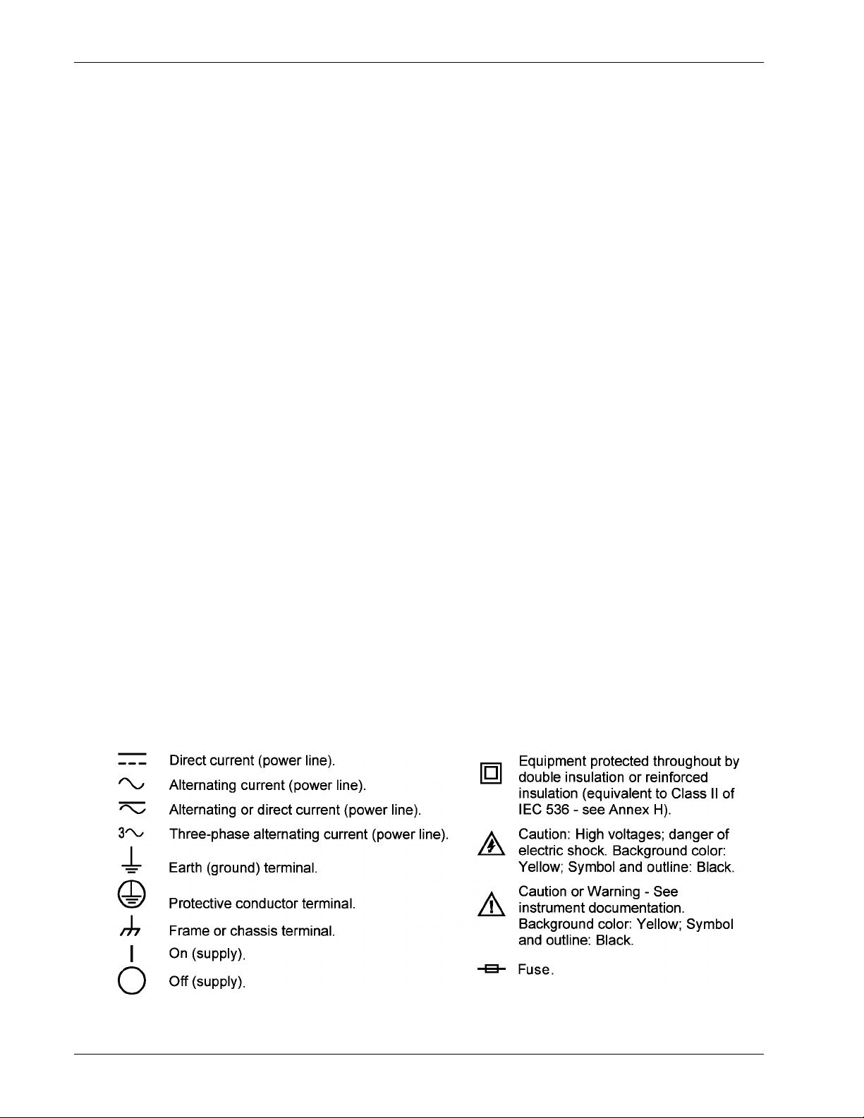
1.3 SAFETY SUMMARY
Observe these general safety precautions during all phases of instrument operation, service, and
repair. Failure to comply with these precautions or with specific warnings elsewhere in this manual
violates safety standards of design, manufacture, and intended instrument use. Lake Shore assumes
no liability for Customer failure to comply with these requirements.
The Model 480 protects the operator and surrounding area from electric shock or burn, mechanical
hazards, excessive temperature, and spread of fire from the instrument. Environmental conditions
outside of the conditions below may pose a hazard to the operator and surrounding area.
• Indoor use.
• Altitude to 2,000 meters.
• Temperature for safe operation: 5 °C to 40 °C.
• Maximum relative humidity: 80% for temperature up to 31 °C decreasing linearly to 50% at 40 °C.
• Power supply voltage fluctuations not to exceed ±10% of the nominal voltage.
• Overvoltage category II.
• Pollution degree 2.
Ground The Instrument. To minimize shock hazard, connect the instrument chassis and cabinet to an
electrical ground. The instrument is equipped with a three-conductor AC power cable. Plug the power
cable into an approved three-contact electrical outlet or use a three-contact adapter with the grounding
wire (green) firmly connected to an electrical ground (safety ground) at the power outlet. The power jack
and mating plug of the power cable meet Underwriters Laboratories (UL) and International
Electrotechnical Commission (IEC) safety standards.
Ventilation. The instrument has ventilation holes in its top and bottom covers. Do not block these holes
when the instrument is turned on.
Do Not Operate In An Explosive Atmosphere. Do not operate the instrument in the presence of
flammable gases or fumes. Operation of any electrical instrument in such an environment constitutes a
definite safety hazard.
Keep Away From Live Circuits. Operating personnel must not remove instrument covers. Refer
component replacement and internal adjustments to qualified maintenance personnel. Do not replace
components with power cable connected. To avoid injuries, always disconnect power and discharge
circuits before touching them.
Do Not Substitute Parts Or Modify Instrument. Do not install substitute parts or perform any
unauthorized modification to the instrument. Return the instrument to an authorized Lake Shore
Cryotronics, Inc. representative for service and repair to ensure that safety features are maintained.
Cleaning. Do not submerge instrument. Clean only exterior with a damp cloth and mild detergent.
1.4 SAFETY SYMBOLS
1-4 Introduction
Lake Shore Model 480 Fluxmeter User’s Manual
CHAPTER 2
MAGNETIC MEASUREMENT OVERVIEW
2.0 GENERAL
This chapter provides an overview of magnetic measurements relating to the operation of the Lake
Shore Model 480 Fluxmeter. Integrating instruments is in Paragraph 2.1; coil characteristics in
Paragraph 2.2, flux overview in Paragraph 2.3, flux density overview in Paragraph 2.4, magnetic
moment overview in Paragraph 2.5, and magnetic potential overview in Paragraph 2.6.
2.1 INTEGRATING INSTRUMENTS
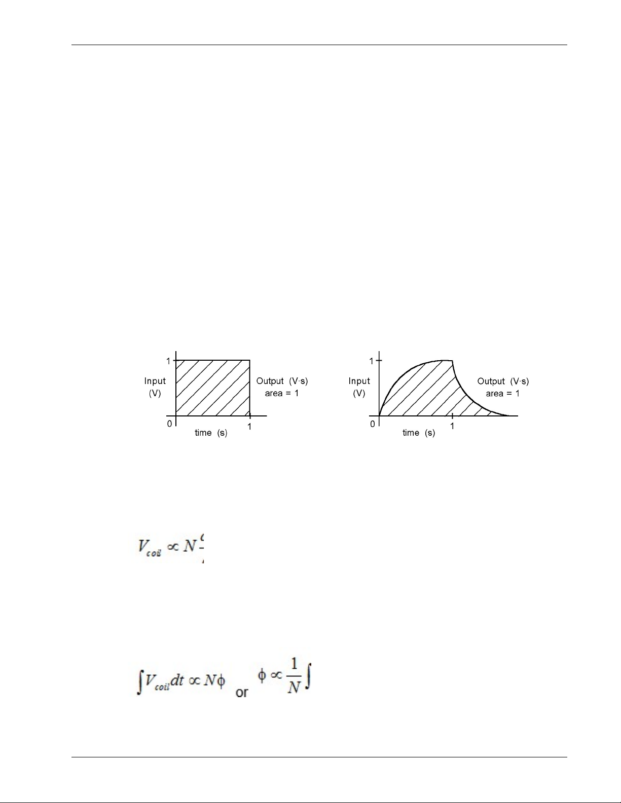
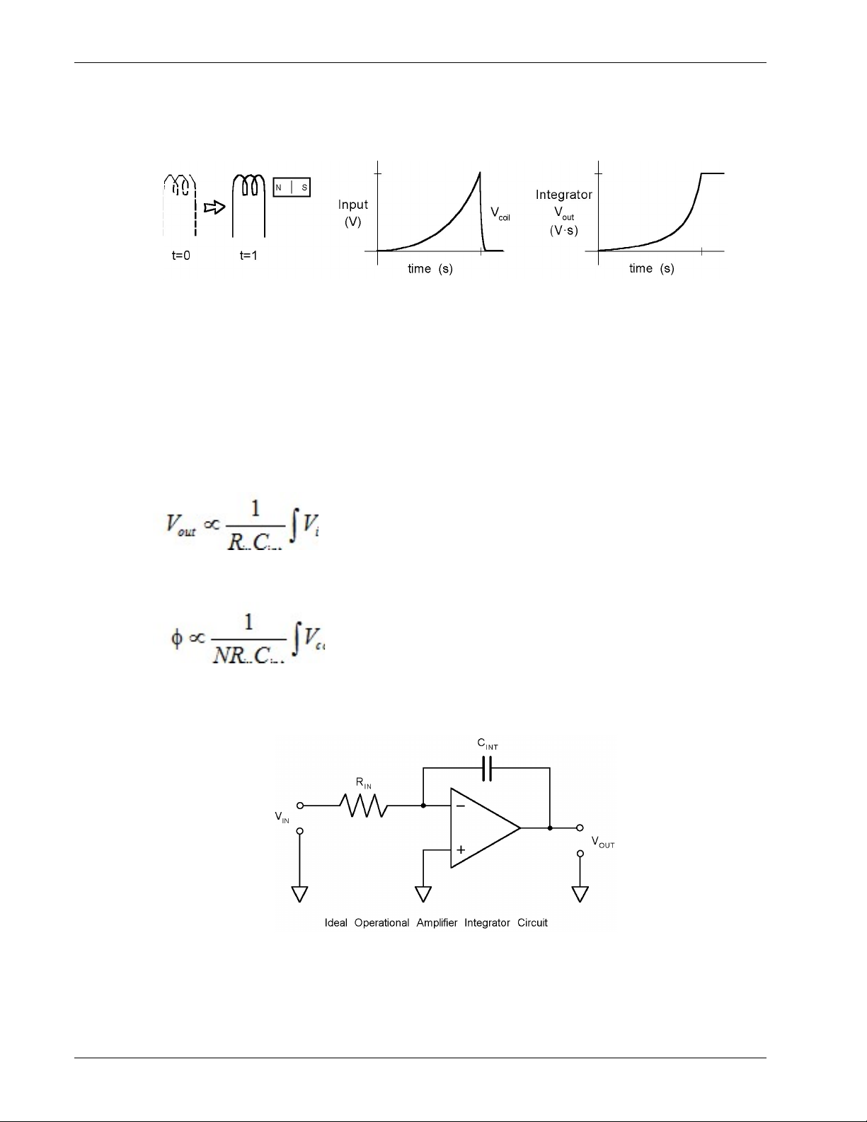
2.1.1 What Is An Integrator?
The output of the integrator in a fluxmeter is proportional to () the voltage at its input as it varies
with time. In the most simple example, a voltage of 1 volt (V) present at the input of a fluxmeter for
1 second (s) results in a reading of 1 volt second (V·s). Volt seconds are the primary unit of
measurement for an integrator. The product of volts and seconds is the area under the voltage line if
it were plotted on a graph against time. When the input voltage changes in an irregular way,
integrator output cannot be calculated by simply multiplying voltage and time. The integrator reacts
continuously to the changing input to give an accurate area measurement.
C-480-2-1.eps
2.1.2 Why Integrators Are Used For Magnetic Measurement
Integrators are used in magnetic measurements because of the physical relationship between coils of
wire and magnetic flux (). The instantaneous voltage produced across a coil (V
the number of turns in the coil (N) times the rate of change in flux (d/dt):
It is inconvenient to use this relationship directly for DC measurements because the voltage
disappears as soon as the flux stops changing. The voltage is also proportional to the rate of change
in flux and not the total change in flux which is often the desired measurement. If V
look at the area under V
plotted against time, the above problems disappear. The integrator output
coil
is proportional to the total change in flux and rate of change does not matter. Expressed
mathematically:
) is proportional to
coil
is integrated to
coil
Magnetic Measurement Overview 2-1
Lake Shore Model 480 Fluxmeter User’s Manual
Why Integrators Are Used For Magnetic Measurement (Continued)
The total flux change can be measured with a fluxmeter as a coil moves near a magnet or as a
magnet moves near a coil.
C-480-2-2.eps
2.1.3 Important Integrator Characteristics
Some parameters that describe the integrator in a fluxmeter are familiar like range and resolution. If
the measurement range is too small, an over range condition can exist. If the range is too large, there
is not enough resolution to make accurate measurements. Available integrator ranges should be
taken into account when designing sensing coils. Ranges are often expressed in volt seconds which
is the fundamental measurement of the integrator. Range can be expressed in flux units if the number
of coil turns is known.
Some characteristics of integrators are not seen in other measurements. Two components dominate
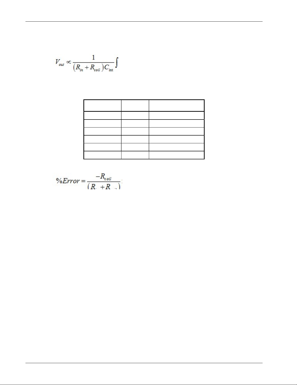
the behavior of an integrator, its input resistance (Rin) and integrating capacitor (C
for a voltage integrator is:
The product Rin C
considered the integrator gain. A more complete expression for flux is:
is called the integrator time constant, but for practical purposes, 1/RinC
int
In the ideal case, Rin and C
could be any value and only their product would matter. In reality there
int
are practical limits to both. Instrument manufacturers optimize the two values for best performance.
Many specifications are given based on specific values of Rin and C
int
).The expression
int
can be
int
.
C-480-2-3.eps
For most users, the choice of fluxmeter Rin and C
has little meaning to their measurement. There
int
are exceptions. The integrator resistance is the sum of input resistance and coil resistance. Coil
resistance must be accounted for when it is a meaningful percentage of Rin. Refer to Paragraph 2.2.3
for more details.
2-2 Magnetic Measurement Overview

Important Integrator Characteristics (Continued)
Lake Shore Model 480 Fluxmeter User’s Manual
Other integrator characteristics that may affect measurements are drift, maximum input voltage, and
maximum and minimum rate of input change. These characteristics are a result of fluxmeter design;
the user often has little control. Check specifications carefully before choosing a fluxmeter for any
application or designing a coil for a fluxmeter.
2.1.4 Reducing Integrator Drift
Drift is the most noticeable and often the largest source of error in integrating fluxmeters. Drift is a
slow change in reading when no change in flux exists. It is caused by any small error voltage at the
integrator input.
Manufacturers spend significant time and effort reducing the drift in instrument integrators.
Component type and value, circuit board layout and manufacturing methods are all optimized to
reduce drift. Temperature change contributes so much to drift that critical components are often
thermally isolated from other parts of the circuit.
Low drift is a result of good fluxmeter design, but users can do things to maintain low drift:
1. Use the instrument on the range specified for lowest drift.
2. Attach sensing coil leads tightly and avoid unnecessary junctions or connections.
3. Keep drafts or other temperature changes away from the coil lead contacts.
4. Allow the instrument to warm up before drift is adjusted and adjust drift as often as practical
during use.
5. Reset the integrator often, before every critical measurement if possible.
Some instruments have built in software algorithms that help adjust drift to zero before measurement.
Other algorithms work in a different way to cancel drift during measurement. It is important to
understand the difference and the affects on measurements.
2.1.5 Dielectric Absorption
All capacitors exhibit a characteristic that can be described as a tendency to rebound from any fast
change. When capacitors are discharged to zero volts momentarily, a small voltage will rise a few
seconds later across the capacitor. Likewise, a rapid charge of a capacitor to some voltage will be
followed by a slight reduction of that potential occurring over several seconds. This characteristic is
usually referred to as Dielectric Absorption. The effect of dielectric absorption in the Model 480
fluxmeter is a slight reading change over several seconds after a larger reading change. This occurs
predictably during reading changes from 0 to some level and more notably occurs when the reading
is reset. A reset from a large, full scale reading will show a “creeping up” of the reading for several
seconds after the reset. The level of this effect is approximately 0.03% of the reading change. The
effect is most noticeable in the first few seconds and stabilizes after 20-30 seconds. For the most
accurate reset of larger measurements an initial reset should be followed by a second reset a few
seconds later.
As inconvenient as this is, capacitor limitations create this condition and cannot be easily remedied.
The capacitor selection for the Model 480 included testing of many vendors and capacitor dielectric
types. The selected capacitors offer the best overall characteristics including that of dielectric
absorption. It is felt that even though this is certainly a source of error for all analog integrating
fluxmeters, the Model 480 is capable of seeing this characteristic with it’s increased resolution while
others have simply ignored it. During instrument factory calibration readings are taken 1 to 2 seconds
after any signal transition. DC Peak, AC and AC Peak readings do not suffer from this anomaly.
Magnetic Measurement Overview 2-3
Lake Shore Model 480 Fluxmeter User’s Manual
2.1.6 Analog Versus Digital Integrators
Most of the integrator discussion in this manual is based on analog integrators. Analog integrators are
made with analog amplifiers, resistors and capacitors. Digital integrators approximate the action of
analog integrators by combining voltage sampling and software integration algorithms. There are
advantages and disadvantages to both types of integrators.
The performance of digital circuitry continues to improve and the price continues to decline. There are
now few analog functions that cannot be approximated digitally. Digital circuits are generally smaller
and have fewer discrete components. Their behavior is more repeatable with fewer calibrations.
Digital integration is likely the best choice to integrate predictable and well behaved signals.
Analog circuit technology is not standing still. Fast changing, high voltage, or very low voltage signals
are still integrated most accurately with analog integrators. The general purpose Model 480 uses an
analog integrator. The instrument must perform well with any type of input signal. The digital circuitry
surrounding the analog integrator offers most of the advantages of a fully digital circuit.
2.1.7 Fluxmeter Measurements In Magnetizers
Magnet materials such as Alnico and Samarium Cobalt are not permanent magnets until they are
conditioned in a magnetizer. The magnetizer produces strong fields by passing current through a coil
fixture. The magnetizer and coil fixture are optimized based on the magnet material and shape. If the
magnetizing field is not strong enough the magnet will not be fully magnetized.
Best cycle times and coil life are achieved when the magnetizer is operated at the minimum voltage
required to attain the needed magnetic field. The Model 480 provides an easy way to measure the
peak field when the magnetizer voltage is being determined during initial setup. Peak field is best
measured in an empty magnetizer fixture. During production magnetizing fixtures age and it is not
uncommon for a coil turn to short. Magnetizer current measurements are not enough to identify many
fixture problems. Peak field should be measured periodically as part of a quality control process and
to determine the general health of the fixture.
Many users want a way to determine if the Model 480 is fast enough to capture the peak field
generated by their magnetizer. The remainder of this section describes how the Model 480 can be
used with even the fastest magnetizers if the sense coil is designed properly. Discussion begins with
an approximation of the wave shape of the field generated by a magnetizer. The maximum rate of
change is then identified and it is shown how that rate of change is the only true limit on peak speed.
Finally coil sensitivity is discussed and examples are given of how to determine appropriate area
turns of a coil.
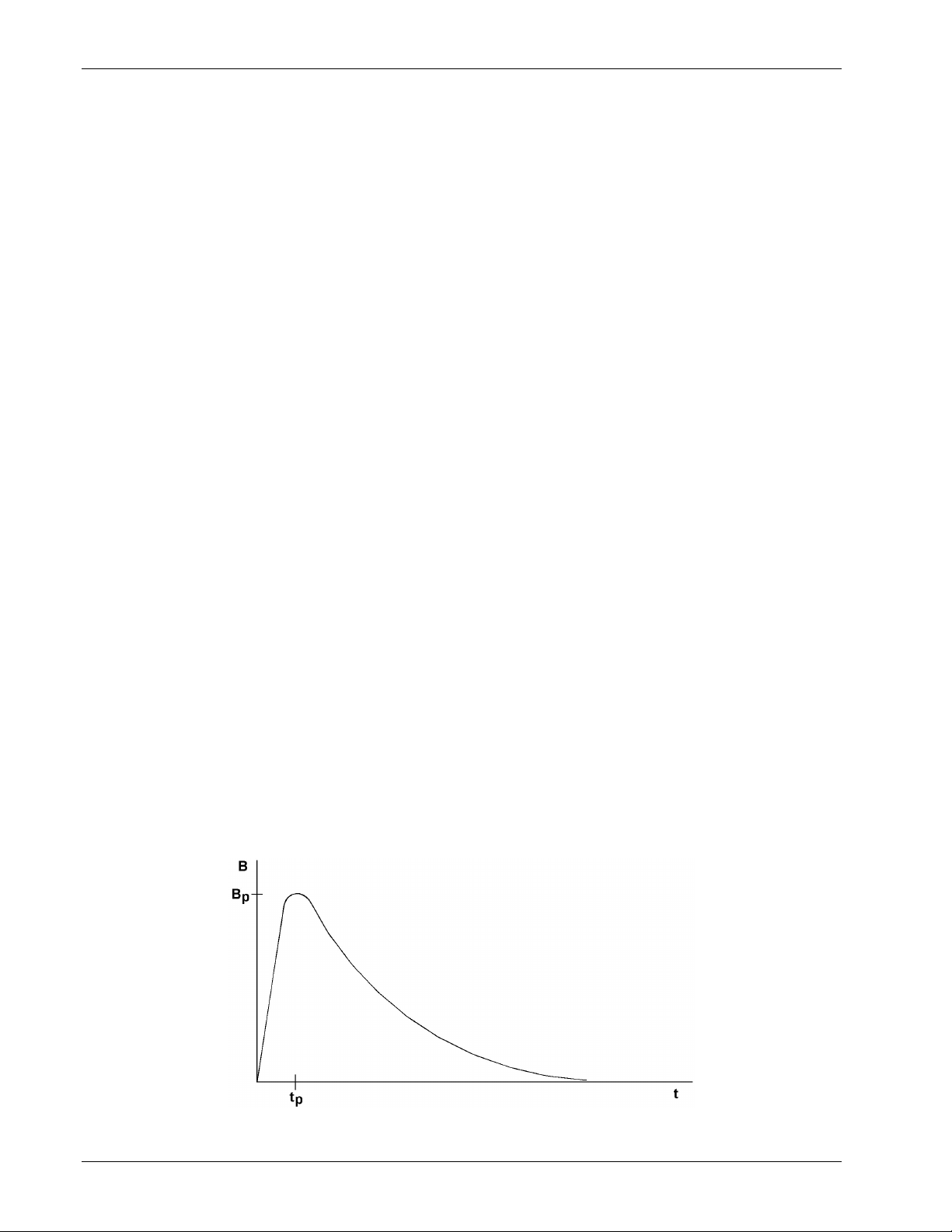
2.1.7.1 The Magnetizer Pulse
In many cases the magnetizer current is provided by a quick, high current discharge of a capacitor
bank. The shape of the magnetic field during this discharge is shown in the figure below.
P-Mag_pulse.bmp
2-4 Magnetic Measurement Overview
Lake Shore Model 480 Fluxmeter User’s Manual
The Magnetizer Pulse (Continued)
The time “tp” to reach peak magnetic field “Bp” is considered the rise time of the pulse. These are
two important parameters to consider when selecting or designing the sense coil for the 480.
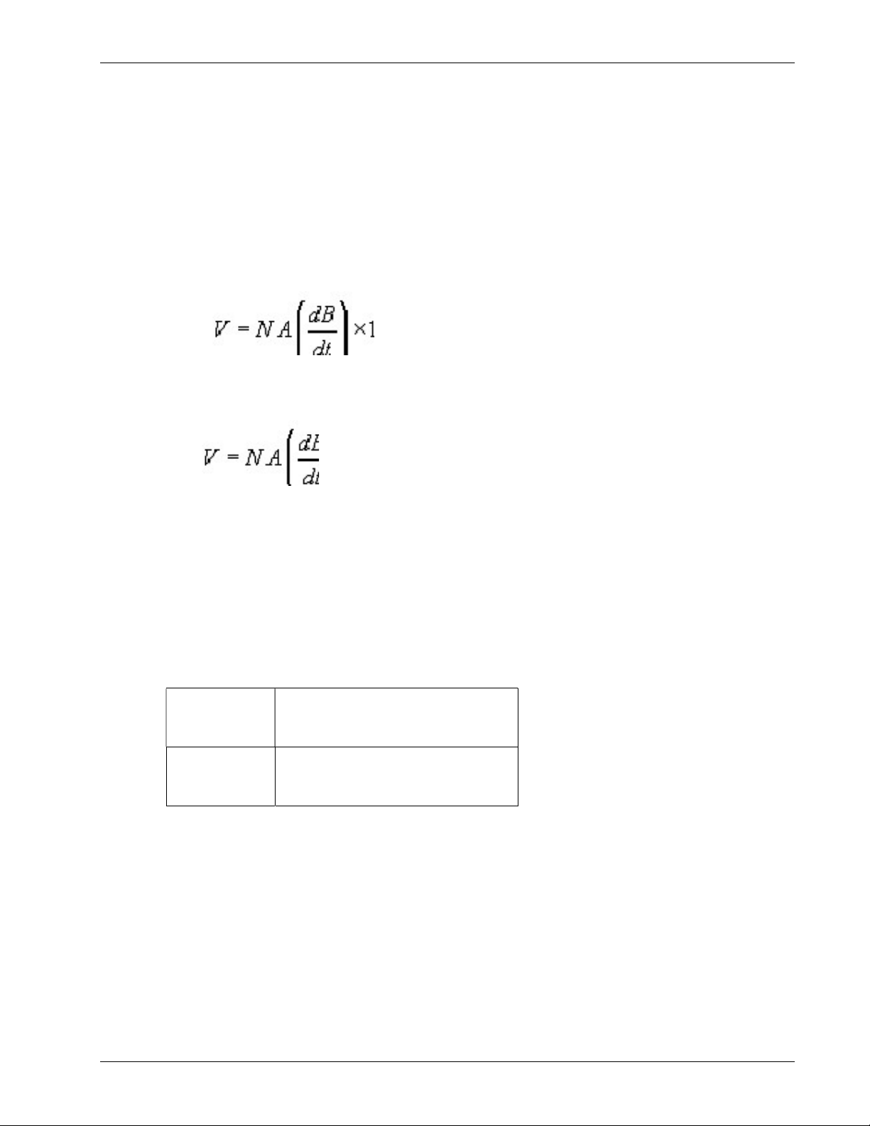
2.1.7.2 Coil Output Voltage Limits
Because of slew rate requirements and safety considerations, the maximum voltage at the coil
output should be limited to 60 volts. The Model 480 Fluxmeter is capable of measuring the fastest
of magnetizer pulses, so long as the 60 volt limit is not exceeded. Therefore, the area turns of the
coil must be matched to the peak field and rise time of the magnetic field pulse.
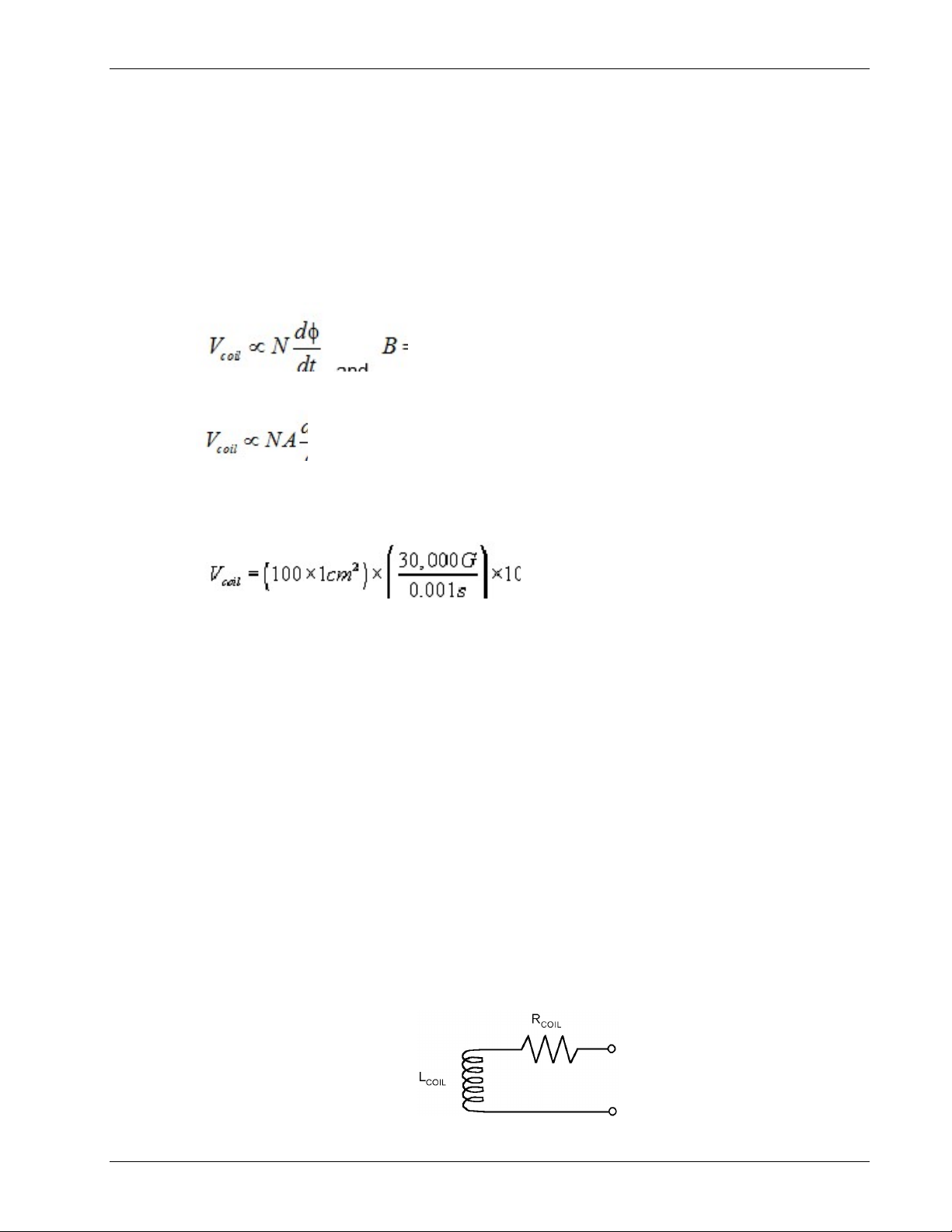
The equation for calculating the coil voltage in CGS units is:
where V = volts, A = cm2, B = gauss, N = number of coil turns, and t = seconds.
The equation for calculating the coil voltage in SI units is:
where V = volts, A = meters2, B = tesla, N = number of coil turns, and t = seconds.
2.1.7.3 Calculation of Minimum Rise Time
What is the fastest pulse allowable? When the area·turns (NA) of the coil and the desired peak field
(Bp) are known, the above equations can be used to calculate the minimum rise time.
tp = NAB/V (SI units)
Calculations of minimum rise times are given for two standard Lake Shore probes.
V = 60 volts and cm2 × 10-4 = meters2
NA = 30 cm2
If Bp = 3 tesla, tp > 150 s
If Bp = 5 tesla, tp > 250 s
If Bp = 7 tesla, tp > 350 s
NA = 100 cm2
If Bp = 3 tesla, tp > 500 s
If Bp = 5 tesla, tp > 833 s
If Bp = 7 tesla, tp > 1200 s (1.2 ms)
2.1.7.4 Calculation Of Area·Turns
Often the user will make his own coil to be used with a specific magnetizing fixture. The maximum
areaturns (NA) needs to be calculated, to ensure the 60 volt input limit is not exceeded. The
equation below can be used.
NA Vtp/Bp meters2 (SI units)
For example, if the rise time tp is 5 s and the peak field Bp is 3 tesla, then the following is a
calculation of the maximum areaturns (NA) to ensure the coil voltage will not exceed 60 volts.
NA (60V) (5 × 10⁻⁶ s) / 3 T = 1 × 10⁻⁴ meter2 = 1 cm2
Magnetic Measurement Overview 2-5
Lake Shore Model 480 Fluxmeter User’s Manual
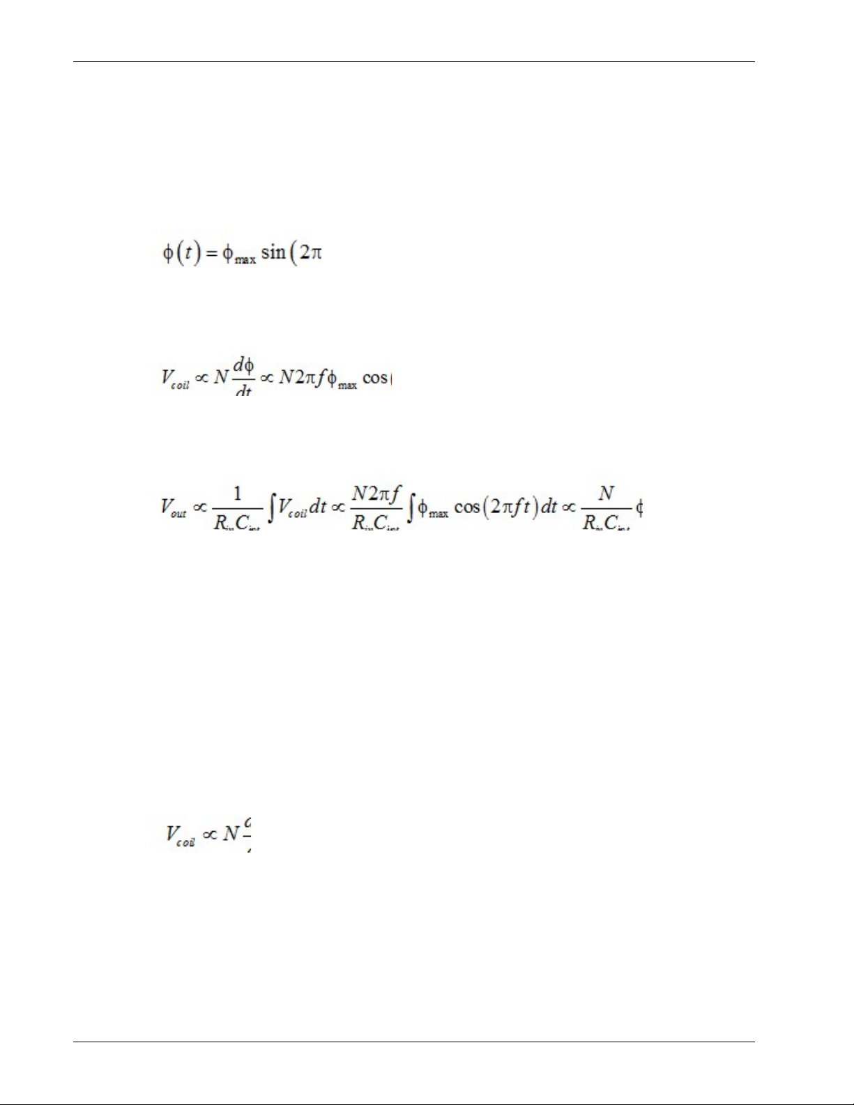
2.1.8 Making AC Measurements
Traditionally, integrating fluxmeters make DC flux measurements where the measured field changes
in a non-periodic way. With only slight modifications to the integrator, a fluxmeter can measure
periodic AC fields. AC measurements are useful in measuring stray fields around transformers or the
poles of a rotating magnet.
A simple expression for a sinusoidal AC flux ((t)) as it varies with time is:
where
is the maximum amplitude of flux, f is the frequency, and t is time.
max
The voltage generated by a sense coil in a field changing this way is proportional to the derivative of
the field:
Note that coil voltage amplitude depends on frequency (f) and flux amplitude (
).
max
The integrator in the instrument reverses the action of the coil and removes the direct frequency
dependence:
The integrator output voltage can be processed by a peak detector to find
converter to find the RMS flux value. The relationships hold true for non-sinusoid AC fields also.
MAX
or through an RMS
The above discussion assumes that the coil inductance and capacitance are small and that the
frequency band of the instrument is not exceeded. Refer to Paragraph 2.2.8 for more details.
2.2 COIL CHARACTERISTICS
One reason fluxmeters are popular is the low cost and simple construction of sensing coils. Some coils
are as simple as a few turns of copper wire. Coil construction gets more complicated to meet special
measurement needs. The inclusion of magnetic materials or special geometries can make a coil a
specialized measurement tool.
2.2.1 Coil Sensitivity
Sensitivity is the instantaneous voltage (V
seen in the equation
) produced for a given rate of change in flux (d/dt). As
coil
the coil voltage is directly proportional to the number of turns (N), as well as the rate of change in flux.
Total change in flux can be measured as the fluxmeter integrates the instantaneous voltage over the
measurement interval.
The following is an example of coil sensitivity related to a permanent magnet. Consider a permanent
magnet has a pole area (A) = 1 cm2 and internal flux density (B) of 1000 G. The flux () = BA =
1,000 Mx. A typical coil of 100 turns (N) that fits snugly around the magnet pole generates an
integrator output of 1000 Mx times 100 turns = 105 MxN = 1mV·s as the magnet is moved into the
coil. A coil of more turns would give a larger output.
2-6 Magnetic Measurement Overview
Coil Sensitivity (Continued)
Number of turns is important to coil design because it determines coil sensitivity. Ideally, increasing
the number of turns always improves coil sensitivity, but in the real world, several factors limit the
number of turns. The most important are coil size, DC resistance of the wire, and peak output voltage.
It is possible for a coil to be too sensitive. Coils should be designed so the instantaneous coil voltage
does not exceed the rated input voltage of the integrator. Magnetizers can create very large
instantaneous coil voltages because their flux changes so quickly (d/dt is large). It is not difficult to
calculate the maximum instantaneous coil voltage if the maximum rate of field change is known.
Using the equations:
Lake Shore Model 480 Fluxmeter User’s Manual
gives us
If V
is in volts, N in turns, A in cm2, B in gauss, and t in seconds, V
coil
magnetizer of modest energy can achieve a flux density change (dB) of 3 T (30,000 G) in 1 ms (dt).
If a coil of 1 cm2 area (A) and 100 turns (N) is in that field, the voltage generated during firing is:
Note that high energy magnetizers with faster rise times can produce dangerous voltages with many
fewer turns.
2.2.2 Coil Size
Application often dictates coil size. Some low field coils may be several feet in diameter to contain
enough changing flux for a measurable coil voltage. Coils for high gradient fields are small as
possible so the coil area does not exceed the uniform field area. Coil size often limits the number of
turns and therefore the sensitivity.
Coils of any length can be used with a fluxmeter, from a single turn to a long solenoid. In practice, the
coil should be limited in length so the same flux lines link all turns. Substantial error occurs when the
flux lines curve out of the coil and link only part of the turns. The fluxmeter assumes all of the turns
see the same flux.
Some coil geometries count on coil length to achieve specific measurement goals. Coil length can
help eliminate the effect of field non-uniformity (Paragraph 2.2.6) or measure magnetic potential
(Paragraph 2.6).
= NA(dB/dt) 10-8. A
coil
2.2.3 Coil Resistance
Coil resistance is sometimes overlooked because it does not appear in ideal equations for a coil or
integrator, but it can limit sensitivity. Wire does have resistance and with enough turns it can become
applicable. Coil resistance must be accounted for when it is a meaningful percentage of the integrator
input resistance.
C-480-2-4.eps
Magnetic Measurement Overview 2-7
Coil Resistance (Continued)
The DC resistance of the coil must be added to the input resistance of the integrator to get an
accurate volt second reading. The expression for a voltage integrator becomes:
Lake Shore Model 480 Fluxmeter User’s Manual
Manufacturers specify integrator resistance for a fluxmeter typically between 1 k to 100 k.
Table 2-1 lists examples of copper wire resistance.
Table 2-1. Examples of Copper Wire Resistance
AWG Annealed
Copper
O.D. inches
at 20 °C
Ohms per 1,000 feet
at 20 °C
40 0.0031 1079.2
38 0.0040 648.2
36 0.0050 414.8
34 0.0063 261.3
32 0.0080 162.0
30 0.0100 103.7
To calculate the percentage error in reading due to coil resistance:
As an example, if R
= 100 k and R
in
= 1 k, an error of -1% results. If R
coil
= 10 k and R
in
an error of -9.1% results if coil resistance is not taken into account.
= 1 k,
coil
2.2.4 Coil Temperature Coefficient
Since coil resistance is temperature dependent, care must be taken when large temperature changes
are expected. The temperature coefficient of resistance for copper magnet wire is +0.4%/°C
(+0.22%/°F). For example, a temperature increase of 10 °C in a 1000 coil causes a resistance
increase of 40 to 1040 . If R
changes from -9.1% to -9.43%.
2.2.5 Coil Orientation
Coil voltage is related to the number of changing flux lines passing through the center of the coil. The
flux measured is a true indication of the number of lines passing through. The angle of the flux lines
passing through the coil does not matter, that is not to say that the orientation of a coil to a magnet
does not matter. Changing coil orientation relative to a magnet often changes the number of flux lines
that pass through the coil. Orient the coil perpendicular to the flux lines for the most repeatable
measurements.
= 10 k, the attenuation from R
in
in the Paragraph 2.2.3 example
coil
2-8 Magnetic Measurement Overview
Lake Shore Model 480 Fluxmeter User’s Manual
2.2.6 Field Uniformity
Flux measurement is a true indication of lines of flux passing through a coil. Field uniformity does not
affect flux measurement, but other magnetic measurements such as flux density assume uniform flux
over the coil area. When measuring flux density in a non-uniform field, the fluxmeter reads the
average flux density.
There are some unique coil configurations that help eliminate the effect of field non-uniformity. The
length to outer diameter ratio of a coil can be optimized to measure flux density at the center of the
coil rather than the average flux density. For more information consult:
Zijlstra, H. Experimental Methods in Magnetism, Wiley, pg. 3, 1967.
Herzog & Tischler, Measurement of Inhomogeneous Magnetic Fields, Review of Scientific
Instruments, Vol. 24, pg. 1000, 1953.
2.2.7 Lead Pickup
Loops other than the sensor coil should be eliminated or minimized. Loops in lead wires see changing
flux just like a coil. Their voltage is an error added or subtracted from the coil voltage. Twisted leads
from the coil to the fluxmeter are recommended to reduce loop area and minimize error voltage.
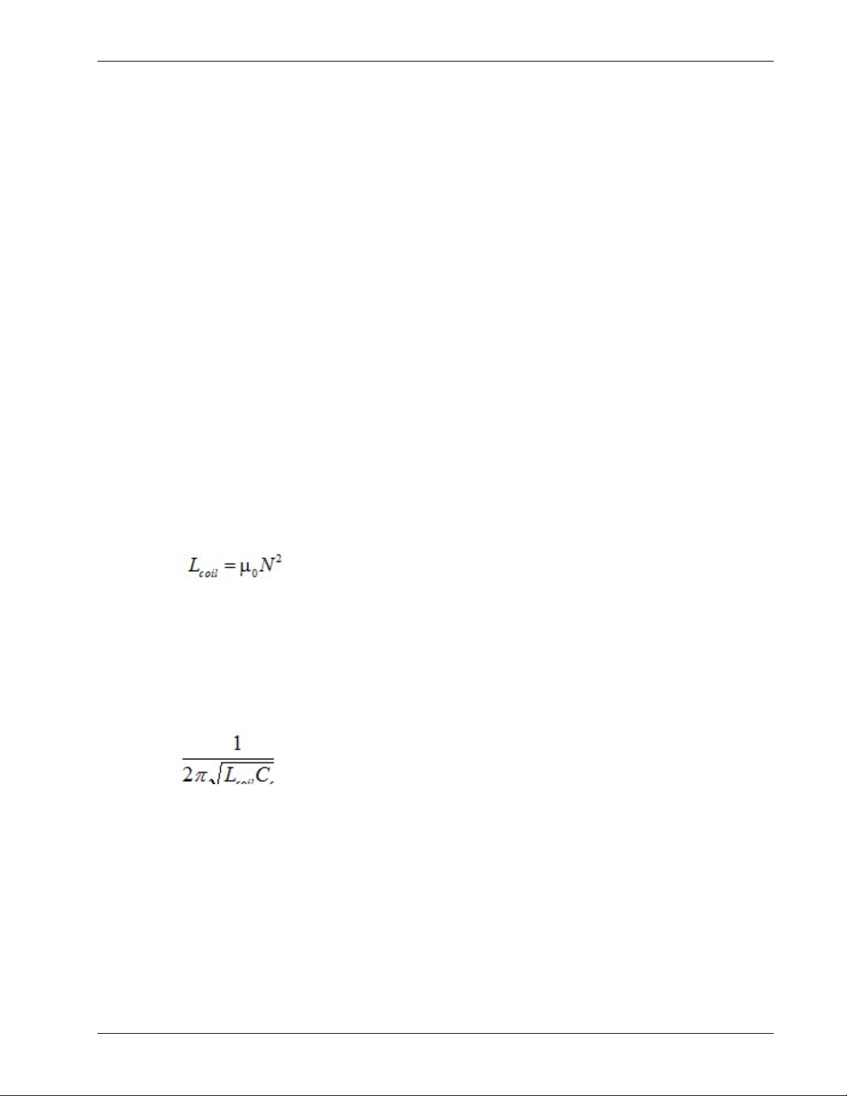
2.2.8 Inductance, Capacitance, and Self Resonance
There are error sources that are only important when making AC or very fast peak DC
measurements.
Keep coil inductance (L
impedance of a coil due to inductance is 2 f L
) small, or it acts similar to coil resistance and reduces sensitivity. The real
coil
coil
resistance of the integrator, or the signal is attenuated. The attenuation changes with frequency
because the impedance does. The equation for calculating inductance of an ideal long solenoid is:
. That value should be small compared to the input
where 0 = 410-7 H/m, N = turns, A = area in m2, l = length in m, and L
Equations for flat search and Helmholtz coils are more complicated because there is no simple
relationship between inductance and length, but the effects of area and number of turns remain
consistent.
There is capacitance between each turn of wire in a coil (C
capacitance itself is most often negligible at frequencies below 50 kHz. However, the capacitance
reacts with the coil inductance to make the coil resonate. Operating anywhere near the coil resonant
frequency gives unpredictable results. The frequency of resonance is:
2.2.9 Lake Shore Coils and Probes
It may be desirable to purchase pre-fabricated sense coils optimized for Model 480 use. Lake Shore
offers search and Helmholtz coils. Dimensions and specifications appear in Chapter 7. They are
designed for every day use with well secured windings and strain relief at connection points.
Factory calibration ensures accurate measurements from the start without field calibrating the coil in a
magnet standard. They also ensure interchangeability of probes and fluxmeters for reproducible
measurements. Lake Shore calibrations use the most accurate standards available. Each coil comes
with calibration data that may include number of turns, area, and resistance.
Lake Shore sense coils are very easy to use. Calibrated coil parameters are usually pre-programmed
into non-volatile memory in the connector. Users need only plug in the connector, turn the power on,
and begin taking measurements.
is in henries (H).
coil
). Impedance resulting from the
coil
Magnetic Measurement Overview 2-9
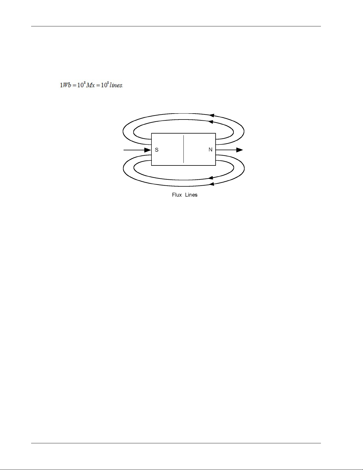
Lake Shore Model 480 Fluxmeter User’s Manual
2.3 FLUX OVERVIEW
Scientists envision a magnetic field as lines of flux leaving the north pole of a magnet and returning to
the south pole. The symbol for flux is . A unit of flux is called a line. In the CGS system, one line of flux
equals one maxwell (Mx). In the SI system, the flux unit is the weber (Wb), where:
Flux is the basic Model 480 magnetic measurement. All other measurements derive from flux
measurement and knowledge of the coil geometry.
C-480-2-5.eps
Flux is measured to indicate energy transferred by a magnet or the energy capacity of a permanent
magnet, to sort magnets, or to determine other magnetic properties such as flux density
(Paragraph 2.4).
The most common way to measure flux is with a coil and integrating fluxmeter. Knowing only the
number of turns in the coil, the fluxmeter measures flux as it changes. Changing flux generates a
voltage in the coil. The coil voltage is integrated by the fluxmeter to show the total change in flux.
2.4 FLUX DENSITY OVERVIEW
2.4.1 What is Flux Density?
A magnetic field consists of flux lines. Flux density is the number of flux lines passing perpendicular
through a plane of unit area (A). The symbol for flux density is B where B = /A. The CGS system
measures flux density in gauss (G) where 1 G = 1 Mx/cm2. The SI system measures flux density in
tesla (T) where 1 T = 1 Wb/m2.
Flux density is important when magnet systems concentrate flux lines into a specific area like the pole
pieces in an electromagnet. Forces generated on current carrying wires like those in a motor
armature are proportional to flux density. Saturation of magnetic core material is also a function of flux
density.
Flux density is often the desired measurement quantity when using a fluxmeter. In a uniform field, flux
density can be calculated by dividing measured flux by the area of the search coil. This can be done
with a fluxmeter as long as the lines of flux are perpendicular to the plane of a flat coil or along the
axis of a longer coil. Hall effect gaussmeters make similar measurements.
Fluxmeters can also measure flux density inside a piece of magnetic material. In this case coils are
wrapped tightly around a material core to ensure the area of the coil is the same as the cross section
of the core. Gaussmeters cannot make this type of measurement.
2-10 Magnetic Measurement Overview

Lake Shore Model 480 Fluxmeter User’s Manual
2.4.2 How Flux Density (B) Differs from Magnetic Field Strength (H)
Flux density is often confused with magnetic field strength. Magnetic field strength is a measure of the
force producing flux lines. The symbol for magnetic field strength is H. In the CGS system, it is
measured in oersteds (Oe). In the SI system, it is measured in amps per meter (A/m):
Flux density and magnetic field strength are related by the permeability () of the magnetic medium.
B = H. Permeability is a measure of how well a material makes a path for flux lines.
The confusion of flux density and magnetic field strength is also related to permeability. In the CGS
system, the permeability of air (of vacuum) is 1. Therefore, 1 G = 1 Oe or B = H in air. Many people
incorrectly assume therefore that in the CGS system, B = H at all times. Adding to the confusion, in
the SI system permeability of air is not 1, so B is not equal to H even in air.
2.5 MAGNETIC MOMENT OVERVIEW
2.5.1 What is Magnetic Moment?
Magnetic moment (m) measures the magnetic field strength (H) produced at points in space by a
plane current loop or a magnetized body. The CGS system measures moment in emu and defines it
as the pole strength of a permanent magnet multiplied by the distance between the poles. This is
sometimes called dipole moment (j = Wb m). The SI system measures moment in amps times square
meters (Am2) and defines it as the current in a conducting loop times the area of the loop or
Magnetic moment is measured to determine various performance factors of permanent magnets. For
example, magnetization (M) can be calculated by dividing magnetic moment by the volume of a
magnet.
A Helmholtz coil and fluxmeter provide a measurement proportional to the magnetic moment of a
permanent magnet, as defined in the CGS System. If the Helmholtz coil constant is known, magnetic
moment can be accurately determined. Uncalibrated coils provide reliable comparative data.
Magnetometers like a vibrating sample magnetometer (VSM) also make moment measurements, but
usually of much smaller values.
2.5.2 Important Parameters of A Helmholtz Coil
For predictable permanent magnet measurements with a Helmholtz coil, the physical dimensions of
the coil must be controlled. A Helmholtz coil is two parallel coils spaced so the average diameter of
the coils is twice the distance between their central planes. No dimension of the coil cross section
should exceed 10% of the coil diameter. Coil diameter should be three to five times the maximum
dimension of the part under evaluation.
An empirically derived calibration constant (Kh) in centimeters is often provided with the coil to allow
a fluxmeter to operate in Wb·cm, a more convenient form of the SI unit Wb·m, where:
Magnetic Measurement Overview 2-11

Lake Shore Model 480 Fluxmeter User’s Manual
2.5.3 Helmholtz Coil Constant Determination (For Non-Lake Shore Coils)
To use a Helmholtz coil and the Model 480 Fluxmeter to make magnet moment measurements, a
Helmholtz Coil Constant is required. Regretfully, this parameter is rarely available. Either the coil is
made in-house or the vendor supplies a coil sensitivity (flux density per current unit) rather than the
coil constant needed. Given below in Paragraphs 2.5.3.1 and .2 are methods of measuring values
which can be used to calculate the constant. Paragraph 2.5.3.3 gives formulas for calculating the coil
constant when coil sensitivity is given.
2.5.3.1 By Measurement of Amperes per Gauss
A gaussmeter and current source are required. In free air, one gauss = one oersted. Directly
measure the current required (amperes) to produce a certain magnetic field (gauss = oersted). In
the calculation of the coil constant, we have to convert oersteds to amperes/centimeter. The Lake
Shore 480 fluxmeter accepts a value for coil constant only in centimeters.
COIL CONSTANT = K = I/H = amperes/oersted = amperes/amperes/cm = cm (units only)
Example: A common Helmholtz coil might require 1 ampere to generate a 30 gauss field.
Thus, K = 1 ampere/30 oersteds = 1 ampere/ (30 × 0.796 A/cm) = 0.0419 cm
2.5.3.2 By Measurement of Amperes per Tesla
Most of the comments above hold, except that the relationship between flux density (B) and
magnetic field strength (H) in the SI system is not as simple as in the cgs system.
H = B/ 0 where 0 = 4 × 10⁻⁷ (for H = A/m), or
H = B/ 0 where 0 = 4 × 10⁻⁵ (for H = A/cm)
COIL CONSTANT = K = I/H = amperes/amperes/cm = cm (units only)
Example: The same coil as above requires 1 ampere to generate a 3 mT (millitesla) field.
Thus, H = 0.003/ (4 × 10⁻⁵) = 23.87 A/cm
K = 1 ampere/(23.87 A/cm) = 0.0419 cm
2.5.3.3 Conversion of Coil Sensitivity
The coil constant conversion factors can be derived by inverting and using the same math as
above.
Coil Sensitivity in gauss per ampere
(1/Sensitivity) × 1.256 = K (cm)
Coil Sensitivity in milligauss per ampere
(1/Sensitivity) × 1256 = K (cm)
Coil Sensitivity in millitesla per ampere
(1/Sensitivity) × 0.1256 = K (cm)
Coil sensitivity in microtesla per ampere
(1/Sensitivity) × 125.6 = K (cm)
2-12 Magnetic Measurement Overview

Lake Shore Model 480 Fluxmeter User’s Manual
2.6 MAGNETIC POTENTIAL OVERVIEW
2.6.1 What is Magnetic Potential?
Magnetic potential (sometimes called magnetostatic potential) is the line integral of magnetizing force
between two points in a magnetic field. It is the scalar value analogous to voltage in an electrical
circuit. The symbol for magnetic potential is U. The CGS system measures magnetic potential in
gilberts (Gb) or oersted times centimeters (Oe·cm). The SI system measures it in amps (A).
Magnetic potential can be used to derive the internal magnetic field strength (H) of a permanent
magnet. The difference in magnetic potential between two points, where no electrical current exists, is
proportional to magnetic field strength (H). With magnetic field strength measured with a potential coil
and flux density measured by other means, the second quadrant operating point of the magnet can
be determined.
A potential coil with a fluxmeter measures the magnetic potential difference between two points on a
permanent magnet. The potential coil is generally a long thin solenoid. The tip of the coil is placed
perpendicular to the pole of a magnet with the other end of the coil out near zero field. The difference
between readings at the two poles is the magnetic potential difference.
2.6.2 Important Parameters of a Potential Coil
It is important that the potential coil length is much larger than its diameter. Coil area and number of
turns determine sensitivity. The coil must be much longer than the volume of magnetic field.
An empirically derived calibration constant (Kp) in amps per volt seconds (A/V·s) is often provided
with the coil to allow a fluxmeter to operate in the SI unit of amps.
Magnetic Measurement Overview 2-13

Lake Shore Model 480 Fluxmeter User’s Manual
This Page Intentionally Left Blank
2-14 Magnetic Measurement Overview
 Loading...