

Lakeshore 340, 3464, 3465, 3462, 3468 Installation Instructions Manual
p
Model 340 Input Option Card Installation
Field Installation
Input option card kit:
(1) 10-conductor ribbon cable
(1) Option card
(4) 32 mm (1.25 in) metal standoffs
(8) 4-40 machine screws
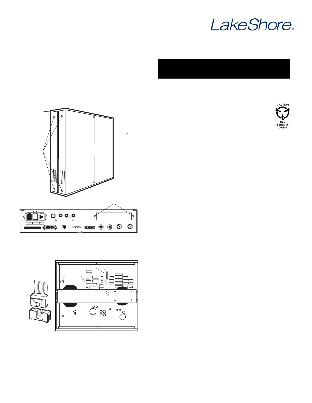
REAR PLASTIC
BEZEL
SIDE COVER
SCREWS
(On Both Sides)
TOP COVER SCREWS
(Remove bottom
cover screws also)
OPTION PLATE SCREWS
To remove top
and bottom
covers, slide
them to the rear
on the tracks.
REAR PANEL
These instructions apply to 3462,
3464, 3465, and 3468 o
Required tools: Small Phillips-head screwdriver and
5/64-inch Allen wrench
CAUTION: The components on this board are
electrostatic discharge sensitive (ESDS)
devices. Wear shock-proof wrist straps
(resistor limited to <5 mA) to prevent injury to
service personnel and to avoid inducing an
electrostatic discharge (ESD) into the device.
1. Turn Model 340 power switch OFF. Unplug power cord
from wall outlet, then instrument.
2. Stand the unit on its face. Use the Allen wrench to
remove the 4 screws on each side of the covers
(Figure 1).
3. Use the small Phillips screwdriver to remove any top
and bottom cover screws; instrument may have 1 or 2
screws on the top and bottom covers.
tion cards
OFF ON
-10% +5%
LINE 100 / 120
FUSE
50-60 Hz
DATA
175 VA MAX
DATA CARD
HEATER FUSE
HEATER OUTPUT
2.5 A
120
220 / 240
2.0 A
1.0 A
IEEE-488 INTERFACE
.25x1.25in SB
5x25mm SB
S
H1 AH1 T5 L4 SR1 RL1 PP0 DC1 DT0 C0 E1
60V MAX
!
WARNING
NO USER SERVICEABLE PARTS INSIDE. REFER
SERVICING TO TRAINED SERVICE PERSONNEL.
EXT
SERIAL I/O
LOHI
!
FOR CONT5INUED PROTECTION AGAINST FIRE HAZARD,
REPLACE FUSE WITH SAME TYPE AND RATING.
DIGITAL I/O
WARNING
RELAYS
LO HI
NC C NO NC C NO
OPTION PLATE
ANALOG
OUT 1
Figure 1. Cover and Option Plate Screws
IGNORE
HOLE #1 HOLE #2
ARROW
NUB
PLUG
SLOT
ANALOG OPTION PLUG
TRANSFORMER ASSEMBLY
Figure 2. Model 340 Mounting Holes
and Analog Option Plug
ANALOG
OUT 2
HOLE #4
HOLE #3
INPUT A
l+V+l-
4. Remove rear plastic bezel. The covers are tracked.
Slide the top and bottom covers to the rear on the
INPUT B
l+V+l-
V-
V-
tracks to remove them.
5. Remove rear panel option plate screws and set aside.
Remove rear panel option plate.
6. With the instrument still standing on its face, turn it to
view the inside circuit board. The upper half of the
circuit board above the transformer assembly contains
four holes where metal standoffs install (Figure 2).
Find Hole #1 to the left between C245 and C265.
Find Hole #2 114 mm (4.5 in) to the right of Hole #1,
and just to the left of C298 and U154.
Find Hole #3 114 mm (4.5 in) to the right of Hole #2,
and just to the left and below the Digital Option plug
(J9).
Find Hole #4 64 mm (2.5 in) above Hole #3, just to the
left and above the digital option plug (J9). Ignore hole to
left and beneath Hole #4.
Into each hole, insert a 4-40 screw through the bottom
of the circuit board, and thread it into a metal standoff
on the top of the circuit board.
Lake Shore Cryotronics, Inc. 575 McCorkle Blvd Westerville, Ohio 43082
Tel: (614) 891-2244 Fax: (614) 818-1600 e-mail: service@lakeshore.com
www.lakeshore.com
F023-07-00 Revision A 1/24/2008
INPUTS
HOLE #1 HOLE #2
Figure 3. Option Card Mounting Holes
and Analog Plug
HOLE #4
PLUG
7. Just beneath the transformer assembly is the analog
option plug (J18). Plug either end of the ribbon cable
into the analog option plug (J18). Slide the arrow nub
down the plug slot for correct positioning (Figure 2).
8. Plug the other end of the ribbon cable into the option
card plug (J3), on the lower right corner of the card
(Figure3).
9. Place the option card on top of the metal standoffs in
the instrument. Fit the card sensor inputs out the rear
panel option opening. Retrieve option plate screws from
Step 5 and use to slightly tighten the option card to the
HOLE #3ANALOG
rear panel.
10. Align the holes in the card with the corresponding metal
standoffs. Insert a 4-40 screw through each option card
hole and thread it to the metal standoff beneath. Go
back and tighten the two screws securing the option
card to the rear panel.
11. Stand instrument on face. Slide top and bottom covers
on. Reposition rear plastic bezel, then rethread all cover
screws. The completed installation of the 3462 card
should look like Figure 4. (Others will look similar.)
LINE
-10% +5%
50-60 Hz
175 VA MAX
DATA CARD
12. Replace power cord. Turn on power switch. To verify
option card installation, press Options, then press
More three times. The Model 340 displays the option in
the REVISION INFORMATION.
OFF ON
100 / 120
FUSE
2.0 A
DATA
.25x1.25in SB
220 / 240
1.0 A
5x25mm SB
120
HEATER FUSE
2.5 A
NO USER SERVICEABLE PARTS INSIDE. REFER
IEEE-488 INTERFACE
S
SERVICING TO TRAINED SERVICE PERSONNEL.
H1 AH1 T5 L4 SR1 RL1 PP0 DC1 DT0 C0 E1
HEATER OUTPUT
!
WARNING
60V MAX
EXT
SERIAL I/O
LOHI
!
WARNING
FOR CONT5INUED PROTECTION AGAINST FIRE HAZARD,
REPLACE FUSE WITH SAME TYPE AND RATING.
DIGITAL I/O
RELAYS
LO HI
NC C NO NC C NO
MODEL 3462
ANALOG
OUT 1
Figure 4. Model 340 Rear Panel with Model 3462 Option Card Installed
ANALOG
OUT 2
INPUT C INPUT D
l+V+l-
INPUT A
l+V+l-
l+V+l-
V-
V-
V-
INPUT B
l+V+l-
V-
Lake Shore Cryotronics, Inc. 575 McCorkle Blvd Westerville, Ohio 43082
Tel: (614) 891-2244 Fax: (614) 818-1600 e-mail: service@lakeshore.com
www.lakeshore.com
F023-07-00 Revision A 1/24/2008
 Loading...