

Lakeshore 336 User Manual
User’s Manual
Model 336
Temperature Controller
Lake Shore Cryotronics, Inc.
575 McCorkle Blvd.
Westerville, Ohio 43082-8888 USA
Methods and apparatus disclosed and described herein have been developed solely on company funds of
Lake Shore Cryotronics, Inc. No government or other contractual support or relationship whatsoever has existed
which in any way affects or mitigates proprietary rights of Lake Shore Cryotronics, Inc. in these developments.
Methods and apparatus disclosed herein may be subject to U.S. Patents existing or applied for.
Lake Shore Cryotronics, Inc. reserves the right to add, improve, modify, or withdraw functions, design modifications,
or products at any time without notice. Lake Shore shall not be liable for errors contained herein or for incidental or
consequential damages in connection with furnishing, performance, or use of this material.
Rev. 1.9 P/N 119-048 7 December 2015
sales@lakeshore.com
service@lakeshore.com
www.lakeshore.com
Fax: (614) 891-1392
Telephone: (614) 891-2243
| www.lakeshore.com

LIMITED WARRANTY STATEMENT
WARRANTY PERIOD: THREE (3) YEARS
1.Lake Shore warrants that products manufactured by Lake Shore (the
"Produ ct") will be f ree from def ects in materials and workmanship for
three years from the date of Purchaser's physical receipt of the Product (the "Warranty Period"). If Lake Shore receives notice of any such
defects during the Warranty Period and the defective Product is
shipped freight prepaid back to Lake Shore, Lake Shore will, at its
option, either repair or replace the Product (if it is so defective) without charge for parts, service labor or associated customary return
shipping cost to the Purchaser. Replacement for the Product may be
by either new or equivalent in performance to new. Replacement or
repaired parts, or a replaced Product, will be warranted for only the
unexpired portion of the original warranty or 90 days (whichever is
greater).
2.Lake Shore warrants the Product only if the Product has been sold
by an authorized Lake Shore employee, sales representative, dea ler or
an authorized Lake Shore original equipment manufacturer (OEM).
3.The Product may contain remanufactured parts equivalent to new
in performance or may have been subject to incidental use when it is
originally sold to the Purchaser.
4.The Warranty Period begins on the date the Product ships from Lake
Shore’s plant.
5.This limited warranty does not apply to defects in the Product
resulting from (a) improper or inadequate installation (unless OT&V
services are performed by Lake Shore), maintenance, repair or calibration, (b) fuses, software, power surges, lightning and non-rechargeable batteries, (c) software, interfacing, parts or other supplies not
furnished by Lake Shore, (d) unauthorized modification or misuse, (e)
operation outside of the published specifications, (f ) improper site
preparation or site maintenance (g) natural disasters such as flood,
fire, wind, or earthquake, or (h) damage during shipment other than
original shipment to you if shipped through a Lake Shore carrier.
6.This limited warranty does not cover: (a) regularly scheduled or ordinary and expected recalibrations of the Product; (b) accessories to the
Product (such as probe tips and cables, holders, wire, grease, varnish,
feedthroughs, etc.); (c) consumables used in conjunction with the
Product (such as probe tips and cables, probe holders, sample tails,
rods and holders, ceramic putty for mounting samples, Hall sample
cards, Hall sample enclosures, etc.); or, (d) non-Lake Shore branded
Products that are integrated with the Product.
7. To the extent allowed by applicable law, this limited warranty is the
only warranty applicable to the Product and replaces all other warranties or conditions, express or implied, including, but not limited to,
the implied warranties or conditions of merchantability and fitness
for a particular purpose. Specifically, except as provided herein, Lake
Shore undertakes no responsibi lity that the products will be fit for any
particular purpose for which you may be buying the Products.
Any implied warranty is limited in duration to the warranty period. No
oral or written information, or advice given by the Company, its
Agents or Employees, shall create a warranty or in any way increase
the scope of this limited warranty. Some countries, states or provinces
do not allow limitations on an implied warranty, so the above limitation or exclusion might not apply to you. This warranty gives you specific legal rights and you might also have other rights that vary from
country to country, state to state or province to province.
8.Further, with regard to the United Nations Convention for International Sale of Goods (CISC,) if CISG is found to apply in relation to this
agreement, which is specifically disclaimed by Lake Shore, then this
limited warranty excludes warranties that: (a) the Product is fit for the
purpose for which goods of the same description would ordinarily be
used, (b) the Product is fit for any particular purpose expressly or
impliedly made known to Lake Shore at the time of the conclusion of
the contract. (c) the Product is contained or packaged in a manner
usual for such goods or in a manner adequate to preserve and protect
such goods where it is shipped by someone other than a carrier hired
by Lake Shore.
9. Lake Shore disclaims any warranties of technological value or of
non-infringement with respect to the Product and Lake Shore shall
have no duty to defend, indemnify, or hold harmless you from and
against any or all damages or costs incurred by you arising from the
infringement of patents or trademarks or violation or copyrights by
the Product.
10.THIS WARRANTY IS NOT TRANSFERRABLE. This warranty is not
transferrable.
11.Except to the extent prohibited by applicable law, neither Lake
Shore nor any of its subsidiaries, affiliates or suppliers will be held liable for direct, special, incidental, consequential or other damages
(including lost profit, lost data, or downtime costs) arising out of the
use, inability to use or result of use of the product, whether based in
warranty, contract, tort or other legal theory, regardless whether or
not Lake Shore has been advised of the possibility of such damages.
Purchaser's use of the Product is entirely at Purchaser's risk. Some
countries, states and provinces do not allow the exclusion of liability
for incidental or consequential damages, so the above limitation may
not apply to you.
12.This limited warranty gives you specific legal rights, and you may
also have other rights that vary within or between jurisdictions where
the product is purchased and/or used. Some jurisdictions do not allow
limitation in certain warranties, and so the above limitations or exclusions of some warranties stated above may not apply to you.
13.Except to the extent allowed by applicable law, the terms of this
limited warranty statement do not exclude, restrict or modify the
mandatory statutory rights applicable to the sale of the product
to you.
Model 336 Temperature Controller

CERTIFICATION
Lake Shore certifies that this product has been inspected and tested
in accordance with its published specifications and that this product
met its published specifications at the time of shipment. The accuracy and calibration of this product at the time of shipment are traceable to the United States National Institute of Standards and
Technology (NIST); formerly known as the National Bureau of Standards (NBS).
FIRMWARE LIMITATIONS
Lake Shore has worked to ensure that the Model 336 firmware is as
free of errors as possible, and that the results you obtain from the
instrument are accurate and reliable. However, as with any computer-based software, the possibility of errors exists.
In any important research, as when using any laboratory equipment,
results should be carefully examined and rechecked before final conclusions are drawn. Neither Lake Shore nor anyone else involved in
the creation or production of this firmware can pay for loss of time,
inconvenience, loss of use of the product, or prop erty damage caused
by this product or its failure to work, or any other incidental or consequential damages. Use of our product implies that you understand
the Lake Shore license agreement and statement of limited warranty.
FIRMWARE LICENSE AGREEMENT
The firmware in this instrument is protected by United States copyright law and international treaty provisions. To maintain the warranty, the code contained in the firmware must not be modified. Any
changes made to the code is at the user's risk. Lake Shore will assume
no responsibility for damage or errors incurred as result of any
changes made to the firmware.
FIRMWARE LICENSE AGREEMENT (continued)
Under the terms of this agreement you may only use the Model 336
firmware as physically installed in the in strument. Archival copies are
strictly forbidden. You may not decompile, disassemble, or reverse
engineer the firmware. If you suspect there are problems with the
firmware, return the instrument to Lake Shore for repair under the
terms of the Limited Warranty specified above. Any unauthorized
duplication or use of the Model 336 firmware in whole or in part, in
print, or in any other storage and retrieval system is forbidden.
TRADEMARK ACKNOWLEDGMENT
Many manufacturers and sellers claim designations used to distinguish their products as trademarks. Where those designations
appear in this manual and Lake Shore was aware of a trademark
claim, they appear with initial capital letters and the ™ or ® symbol.
Alumel™ and Chromel™ are trademarks of
Conceptech, Inc., Corporation
Apiezon™ is a registered trademark of M&I Materials, Ltd.
CalCurve™, Cernox™, SoftCal™, Rox™, Curve Handler™ are trademarks of Lake Shore Cryotronics, Inc.
Java™ is a registered trademark of Sun Microsystems, Inc.
of Santa Clara, CA
LabVIEW® is a registered trademark of National Instruments.
Mac® is a registered trademark of Apple, Inc., registered in the U.S and
other countries.
Microsoft Windows®, Excel®, and Windows Vista® are registered
trademarks of Microsoft Corporation in the United States and other
countries.
Stycast® is a trademark of Emerson & Cuming.
WinZip™ is a registered trademark of Nico Mak of Connecticut.
Copyright 2009 - 2015 Lake Shore Cryotronics, Inc. All rights reserved. No portion of this manual may be
reproduced, stored in a retrieval system, or transmitted, in any form or by any means, electronic, mechanical,
photocopying, recording, or otherwise, without the express written permission of Lake Shore.
| www.lakeshore.com
Model 336 Temperature Controller

Electromagnetic Compatibility (EMC) for the Model 336 Temperature Controller
Electromagnetic Compatibility (EMC) of electronic equipment is a growing concern worldwide. Emissions of and
immunity to electromagnetic interference is now part of the design and manufacture of most electronics. To qualify
for the CE Mark, the Model 336 meets or exceeds the requirements of the European EMC Directive 89/336/EEC as a
CLASS A product. A Class A product is allowed to radiate more RF than a Class B product and must include the following warning:
WARNING:This is a Class A product. In a domestic environment, this product may cause radio interference in which
case the user may be required to take adequate measures.
The instrument was tested under normal operating conditions with sensor and interface cables attached. If the
installation and operating instructions in the User's Manual are followed, there should be no degradation in EMC
performance.
This instrument is not intended for use in close proximity to RF Transmitters such as two-way radios and cell
phones. Exposure to RF interference greater than that found in a typical laboratory environment may disturb the
sensitive measurement circuitry of the instrument.
Pay special attention to instrument cabling. Improperly installed cabling may defeat even the best EMC protection.
For the best performance from any precision instrument, follow the grounding and shielding instructions in the
User's Manual. In addition, the installer of the Model 336 should consider the following:
D Shield measurement and computer interface cables.
D Leave no unused or unterminated cables attached to the instrument.
D Make cable runs as short and direct as possible. Higher radiated emissions are possible with long cables.
D Do not tightly bundle cables that carry different types of signals.
| www.lakeshore.com

Model 336 Temperature Controller

i
Table of Contents
Chapter 1
Introduction
Chapter 2
Cooling System Design and
Temperature
Control
1.1 Product Description . . . . . . . . . . . . . . . . . . . . . . . . . . . . . . . . . . . . . . . . . . . . . . . . . . . . . . . . . . . . . . . . . . 1
1.1.1 Sensor Inputs . . . . . . . . . . . . . . . . . . . . . . . . . . . . . . . . . . . . . . . . . . . . . . . . . . . . . . . . . . . . . . . . . . . 2
1.1.2 Temperature Control . . . . . . . . . . . . . . . . . . . . . . . . . . . . . . . . . . . . . . . . . . . . . . . . . . . . . . . . . . . 2
1.1.3 Interface . . . . . . . . . . . . . . . . . . . . . . . . . . . . . . . . . . . . . . . . . . . . . . . . . . . . . . . . . . . . . . . . . . . . . . . . 3
1.1.4 Configurable Display . . . . . . . . . . . . . . . . . . . . . . . . . . . . . . . . . . . . . . . . . . . . . . . . . . . . . . . . . . . 4
1.1.5 Three Option Cards . . . . . . . . . . . . . . . . . . . . . . . . . . . . . . . . . . . . . . . . . . . . . . . . . . . . . . . . . . . . . 4
1.2 Sensor Selection . . . . . . . . . . . . . . . . . . . . . . . . . . . . . . . . . . . . . . . . . . . . . . . . . . . . . . . . . . . . . . . . . . . . . . 4
1.3 Model 336 Specifications . . . . . . . . . . . . . . . . . . . . . . . . . . . . . . . . . . . . . . . . . . . . . . . . . . . . . . . . . . . . 7
1.3.1 Input Specifications . . . . . . . . . . . . . . . . . . . . . . . . . . . . . . . . . . . . . . . . . . . . . . . . . . . . . . . . . . . . 7
1.3.2 Sensor Input Configuration . . . . . . . . . . . . . . . . . . . . . . . . . . . . . . . . . . . . . . . . . . . . . . . . . . . . 8
1.3.3 Thermometry. . . . . . . . . . . . . . . . . . . . . . . . . . . . . . . . . . . . . . . . . . . . . . . . . . . . . . . . . . . . . . . . . . . 8
1.3.4 Control. . . . . . . . . . . . . . . . . . . . . . . . . . . . . . . . . . . . . . . . . . . . . . . . . . . . . . . . . . . . . . . . . . . . . . . . . . 9
1.3.4.1 Heater Outputs (Outputs 1 and 2) . . . . . . . . . . . . . . . . . . . . . . . . . . . . . . . . . . . . 9
1.3.4.2 Unpowered Analog Outputs (Outputs 3 and 4) . . . . . . . . . . . . . . . . . . . . . .10
1.3.5 Front Panel . . . . . . . . . . . . . . . . . . . . . . . . . . . . . . . . . . . . . . . . . . . . . . . . . . . . . . . . . . . . . . . . . . . 10
1.3.6 Interface . . . . . . . . . . . . . . . . . . . . . . . . . . . . . . . . . . . . . . . . . . . . . . . . . . . . . . . . . . . . . . . . . . . . . . 11
1.3.7 General . . . . . . . . . . . . . . . . . . . . . . . . . . . . . . . . . . . . . . . . . . . . . . . . . . . . . . . . . . . . . . . . . . . . . . . 11
1.4 Safety Summary and Symbols . . . . . . . . . . . . . . . . . . . . . . . . . . . . . . . . . . . . . . . . . . . . . . . . . . . . . . 12
2.1 General . . . . . . . . . . . . . . . . . . . . . . . . . . . . . . . . . . . . . . . . . . . . . . . . . . . . . . . . . . . . . . . . . . . . . . . . . . . . . . .15
2.2 Temperature Sensor Selection . . . . . . . . . . . . . . . . . . . . . . . . . . . . . . . . . . . . . . . . . . . . . . . . . . . . . .15
2.2.1 Temperature Range . . . . . . . . . . . . . . . . . . . . . . . . . . . . . . . . . . . . . . . . . . . . . . . . . . . . . . . . . . 15
2.2.2 Sensor Sensitivity . . . . . . . . . . . . . . . . . . . . . . . . . . . . . . . . . . . . . . . . . . . . . . . . . . . . . . . . . . . . 15
2.2.3 Environmental Conditions . . . . . . . . . . . . . . . . . . . . . . . . . . . . . . . . . . . . . . . . . . . . . . . . . . . 16
2.2.4 Measurement Accuracy . . . . . . . . . . . . . . . . . . . . . . . . . . . . . . . . . . . . . . . . . . . . . . . . . . . . . . 16
2.2.5 Sensor Package . . . . . . . . . . . . . . . . . . . . . . . . . . . . . . . . . . . . . . . . . . . . . . . . . . . . . . . . . . . . . . . 16
2.3 Sensor Calibrations . . . . . . . . . . . . . . . . . . . . . . . . . . . . . . . . . . . . . . . . . . . . . . . . . . . . . . . . . . . . . . . . .16
2.3.1 Precision Calibration . . . . . . . . . . . . . . . . . . . . . . . . . . . . . . . . . . . . . . . . . . . . . . . . . . . . . . . . . 17
2.3.2 SoftCal™. . . . . . . . . . . . . . . . . . . . . . . . . . . . . . . . . . . . . . . . . . . . . . . . . . . . . . . . . . . . . . . . . . . . . . 17
2.3.3 Sensors Using Standard Curves . . . . . . . . . . . . . . . . . . . . . . . . . . . . . . . . . . . . . . . . . . . . . . 17
2.3.4 Curve Handler™ . . . . . . . . . . . . . . . . . . . . . . . . . . . . . . . . . . . . . . . . . . . . . . . . . . . . . . . . . . . . . . 17
2.4 Sensor Installation . . . . . . . . . . . . . . . . . . . . . . . . . . . . . . . . . . . . . . . . . . . . . . . . . . . . . . . . . . . . . . . . . . . 18
2.4.1 Mounting Materials . . . . . . . . . . . . . . . . . . . . . . . . . . . . . . . . . . . . . . . . . . . . . . . . . . . . . . . . . . 18
2.4.2 Sensor Location . . . . . . . . . . . . . . . . . . . . . . . . . . . . . . . . . . . . . . . . . . . . . . . . . . . . . . . . . . . . . . 18
2.4.3 Thermal Conductivity . . . . . . . . . . . . . . . . . . . . . . . . . . . . . . . . . . . . . . . . . . . . . . . . . . . . . . . . 18
2.4.4 Contact Area. . . . . . . . . . . . . . . . . . . . . . . . . . . . . . . . . . . . . . . . . . . . . . . . . . . . . . . . . . . . . . . . . . 19
2.4.5 Contact Pressure . . . . . . . . . . . . . . . . . . . . . . . . . . . . . . . . . . . . . . . . . . . . . . . . . . . . . . . . . . . . . 19
2.4.6 Lead Wire . . . . . . . . . . . . . . . . . . . . . . . . . . . . . . . . . . . . . . . . . . . . . . . . . . . . . . . . . . . . . . . . . . . . . 19
2.4.7 Lead Soldering. . . . . . . . . . . . . . . . . . . . . . . . . . . . . . . . . . . . . . . . . . . . . . . . . . . . . . . . . . . . . . . . 20
2.4.8 Thermal Anchoring Leads . . . . . . . . . . . . . . . . . . . . . . . . . . . . . . . . . . . . . . . . . . . . . . . . . . . . 20
2.4.9 Thermal Radiation . . . . . . . . . . . . . . . . . . . . . . . . . . . . . . . . . . . . . . . . . . . . . . . . . . . . . . . . . . . 20
2.5 Heater Selection and Installation . . . . . . . . . . . . . . . . . . . . . . . . . . . . . . . . . . . . . . . . . . . . . . . . . . . 21
2.5.1 Heater Resistance and Power. . . . . . . . . . . . . . . . . . . . . . . . . . . . . . . . . . . . . . . . . . . . . . . . 21
2.5.2 Heater Location . . . . . . . . . . . . . . . . . . . . . . . . . . . . . . . . . . . . . . . . . . . . . . . . . . . . . . . . . . . . . . 22
2.5.3 Heater Types . . . . . . . . . . . . . . . . . . . . . . . . . . . . . . . . . . . . . . . . . . . . . . . . . . . . . . . . . . . . . . . . . 22
2.5.4 Heater Wiring . . . . . . . . . . . . . . . . . . . . . . . . . . . . . . . . . . . . . . . . . . . . . . . . . . . . . . . . . . . . . . . . 22
2.6 Consideration for Good Control . . . . . . . . . . . . . . . . . . . . . . . . . . . . . . . . . . . . . . . . . . . . . . . . . . . . .23
2.6.1 Thermal Conductivity . . . . . . . . . . . . . . . . . . . . . . . . . . . . . . . . . . . . . . . . . . . . . . . . . . . . . . . . 23
2.6.2 Thermal Lag . . . . . . . . . . . . . . . . . . . . . . . . . . . . . . . . . . . . . . . . . . . . . . . . . . . . . . . . . . . . . . . . . . 23
2.6.3 Two-Sensor Approach . . . . . . . . . . . . . . . . . . . . . . . . . . . . . . . . . . . . . . . . . . . . . . . . . . . . . . . . 23
2.6.4 Thermal Mass . . . . . . . . . . . . . . . . . . . . . . . . . . . . . . . . . . . . . . . . . . . . . . . . . . . . . . . . . . . . . . . . 23
| www.lakeshore.com

2.6.5 System Non-Linearity. . . . . . . . . . . . . . . . . . . . . . . . . . . . . . . . . . . . . . . . . . . . . . . . . . . . . . . . . 23
2.7 PID Control . . . . . . . . . . . . . . . . . . . . . . . . . . . . . . . . . . . . . . . . . . . . . . . . . . . . . . . . . . . . . . . . . . . . . . . . . . 24
2.7.1 Proportional (P) . . . . . . . . . . . . . . . . . . . . . . . . . . . . . . . . . . . . . . . . . . . . . . . . . . . . . . . . . . . . . . . 24
2.7.2 Integral (I) . . . . . . . . . . . . . . . . . . . . . . . . . . . . . . . . . . . . . . . . . . . . . . . . . . . . . . . . . . . . . . . . . . . . . 24
2.7.3 Derivative (D). . . . . . . . . . . . . . . . . . . . . . . . . . . . . . . . . . . . . . . . . . . . . . . . . . . . . . . . . . . . . . . . . . 25
2.7.4 Manual Output. . . . . . . . . . . . . . . . . . . . . . . . . . . . . . . . . . . . . . . . . . . . . . . . . . . . . . . . . . . . . . . . 25
2.8 Manual Tuning . . . . . . . . . . . . . . . . . . . . . . . . . . . . . . . . . . . . . . . . . . . . . . . . . . . . . . . . . . . . . . . . . . . . . . 27
2.8.1 Setting Heater Range . . . . . . . . . . . . . . . . . . . . . . . . . . . . . . . . . . . . . . . . . . . . . . . . . . . . . . . . . 27
2.8.2 Tuning Proportional . . . . . . . . . . . . . . . . . . . . . . . . . . . . . . . . . . . . . . . . . . . . . . . . . . . . . . . . . . 27
2.8.3 Tuning Integral . . . . . . . . . . . . . . . . . . . . . . . . . . . . . . . . . . . . . . . . . . . . . . . . . . . . . . . . . . . . . . . . 28
2.8.4 Tuning Derivative . . . . . . . . . . . . . . . . . . . . . . . . . . . . . . . . . . . . . . . . . . . . . . . . . . . . . . . . . . . . . 29
2.9 Autotuning . . . . . . . . . . . . . . . . . . . . . . . . . . . . . . . . . . . . . . . . . . . . . . . . . . . . . . . . . . . . . . . . . . . . . . . . . . 29
2.10 Zone Tuning . . . . . . . . . . . . . . . . . . . . . . . . . . . . . . . . . . . . . . . . . . . . . . . . . . . . . . . . . . . . . . . . . . . . . . . . 30
2.11 Thermoelectric Devices . . . . . . . . . . . . . . . . . . . . . . . . . . . . . . . . . . . . . . . . . . . . . . . . . . . . . . . . . . . . 30
Chapter 3
Installation
3.1 General . . . . . . . . . . . . . . . . . . . . . . . . . . . . . . . . . . . . . . . . . . . . . . . . . . . . . . . . . . . . . . . . . . . . . . . . . . . . . . 31
3.2 Inspection and Unpacking . . . . . . . . . . . . . . . . . . . . . . . . . . . . . . . . . . . . . . . . . . . . . . . . . . . . . . . . . . 31
3.3 Rear Panel Definition . . . . . . . . . . . . . . . . . . . . . . . . . . . . . . . . . . . . . . . . . . . . . . . . . . . . . . . . . . . . . . . . 31
3.4 Line Input Assembly . . . . . . . . . . . . . . . . . . . . . . . . . . . . . . . . . . . . . . . . . . . . . . . . . . . . . . . . . . . . . . . . . 32
3.4.1 Line Voltage . . . . . . . . . . . . . . . . . . . . . . . . . . . . . . . . . . . . . . . . . . . . . . . . . . . . . . . . . . . . . . . . . . . 32
3.4.2 Line Fuse and Fuse Holder . . . . . . . . . . . . . . . . . . . . . . . . . . . . . . . . . . . . . . . . . . . . . . . . . . . . 32
3.4.3 Power Cord . . . . . . . . . . . . . . . . . . . . . . . . . . . . . . . . . . . . . . . . . . . . . . . . . . . . . . . . . . . . . . . . . . . 33
3.4.4 Power Switch . . . . . . . . . . . . . . . . . . . . . . . . . . . . . . . . . . . . . . . . . . . . . . . . . . . . . . . . . . . . . . . . . 33
3.5 Diode/Resistor Sensor Inputs . . . . . . . . . . . . . . . . . . . . . . . . . . . . . . . . . . . . . . . . . . . . . . . . . . . . . . . 33
3.5.1 Sensor Input Connector and Pinout . . . . . . . . . . . . . . . . . . . . . . . . . . . . . . . . . . . . . . . . . . 33
3.5.2 Sensor Lead Cable . . . . . . . . . . . . . . . . . . . . . . . . . . . . . . . . . . . . . . . . . . . . . . . . . . . . . . . . . . . . 34
3.5.3 Grounding and Shielding Sensor Leads . . . . . . . . . . . . . . . . . . . . . . . . . . . . . . . . . . . . . . 34
3.5.4 Sensor Polarity . . . . . . . . . . . . . . . . . . . . . . . . . . . . . . . . . . . . . . . . . . . . . . . . . . . . . . . . . . . . . . . . 34
3.5.5 Four-Lead Sensor Measurement . . . . . . . . . . . . . . . . . . . . . . . . . . . . . . . . . . . . . . . . . . . . . 35
3.5.6 Two-Lead Sensor Measurement . . . . . . . . . . . . . . . . . . . . . . . . . . . . . . . . . . . . . . . . . . . . . 35
3.5.7 Lowering Measurement Noise . . . . . . . . . . . . . . . . . . . . . . . . . . . . . . . . . . . . . . . . . . . . . . . 36
3.6 Capacitance Sensor Inputs (Model 3061) . . . . . . . . . . . . . . . . . . . . . . . . . . . . . . . . . . . . . . . . . . 36
3.6.1 Wiring, Guarding and Shielding . . . . . . . . . . . . . . . . . . . . . . . . . . . . . . . . . . . . . . . . . . . . . . 37
3.7 Thermocouple Sensor Inputs (Thermocouple Model 3060) . . . . . . . . . . . . . . . . . . . . . . . 37
3.7.1 Sensor Input Terminals . . . . . . . . . . . . . . . . . . . . . . . . . . . . . . . . . . . . . . . . . . . . . . . . . . . . . . . 37
3.7.2 Thermocouple Installation . . . . . . . . . . . . . . . . . . . . . . . . . . . . . . . . . . . . . . . . . . . . . . . . . . . 38
3.7.3 Grounding and Shielding . . . . . . . . . . . . . . . . . . . . . . . . . . . . . . . . . . . . . . . . . . . . . . . . . . . . . 38
3.8 Heater Output Setup . . . . . . . . . . . . . . . . . . . . . . . . . . . . . . . . . . . . . . . . . . . . . . . . . . . . . . . . . . . . . . . . 38
3.8.1 Heater Output Description . . . . . . . . . . . . . . . . . . . . . . . . . . . . . . . . . . . . . . . . . . . . . . . . . . . 38
3.8.2 Heater Output Connectors . . . . . . . . . . . . . . . . . . . . . . . . . . . . . . . . . . . . . . . . . . . . . . . . . . . 39
3.8.3 Heater Output Wiring . . . . . . . . . . . . . . . . . . . . . . . . . . . . . . . . . . . . . . . . . . . . . . . . . . . . . . . . 39
3.8.4 Heater Output Noise . . . . . . . . . . . . . . . . . . . . . . . . . . . . . . . . . . . . . . . . . . . . . . . . . . . . . . . . . 39
3.8.5 Powering Outputs 3 and 4 Using an External Power Supply . . . . . . . . . . . . . . . . 39
3.8.5.1 Choosing a Power Supply . . . . . . . . . . . . . . . . . . . . . . . . . . . . . . . . . . . . . . . . . . . . 40
3.8.5.2 Power Supply Setup . . . . . . . . . . . . . . . . . . . . . . . . . . . . . . . . . . . . . . . . . . . . . . . . . . 40
3.8.5.3 Connecting to the Model 336 . . . . . . . . . . . . . . . . . . . . . . . . . . . . . . . . . . . . . . . . 41
3.8.5.4 Programming Voltages Under 10 V . . . . . . . . . . . . . . . . . . . . . . . . . . . . . . . . . . 41
Chapter 4
Operation
Model 336 Temperature Controller
4.1 General . . . . . . . . . . . . . . . . . . . . . . . . . . . . . . . . . . . . . . . . . . . . . . . . . . . . . . . . . . . . . . . . . . . . . . . . . . . . . . 43
4.1.1 Understanding Menu Navigation . . . . . . . . . . . . . . . . . . . . . . . . . . . . . . . . . . . . . . . . . . . . 43
4.2 Front Panel Description . . . . . . . . . . . . . . . . . . . . . . . . . . . . . . . . . . . . . . . . . . . . . . . . . . . . . . . . . . . . . 44
4.2.1 Keypad Definitions . . . . . . . . . . . . . . . . . . . . . . . . . . . . . . . . . . . . . . . . . . . . . . . . . . . . . . . . . . . 44
4.2.1.1 Direct Operation Keys . . . . . . . . . . . . . . . . . . . . . . . . . . . . . . . . . . . . . . . . . . . . . . . . 44
4.2.1.2 Menu/Number Pad Keys . . . . . . . . . . . . . . . . . . . . . . . . . . . . . . . . . . . . . . . . . . . . . 45
4.2.2 Annunciators . . . . . . . . . . . . . . . . . . . . . . . . . . . . . . . . . . . . . . . . . . . . . . . . . . . . . . . . . . . . . . . . . 45
4.2.3 General Keypad Operation . . . . . . . . . . . . . . . . . . . . . . . . . . . . . . . . . . . . . . . . . . . . . . . . . . . 46
4.3 Display Setup . . . . . . . . . . . . . . . . . . . . . . . . . . . . . . . . . . . . . . . . . . . . . . . . . . . . . . . . . . . . . . . . . . . . . . . . 47

iii
4.3.1 Display Modes . . . . . . . . . . . . . . . . . . . . . . . . . . . . . . . . . . . . . . . . . . . . . . . . . . . . . . . . . . . . . . . .47
4.3.1.1 Four Loop Mode . . . . . . . . . . . . . . . . . . . . . . . . . . . . . . . . . . . . . . . . . . . . . . . . . . . . . . 47
4.3.1.2 All Inputs Mode . . . . . . . . . . . . . . . . . . . . . . . . . . . . . . . . . . . . . . . . . . . . . . . . . . . . . . . 48
4.3.1.3 Input Display Modes . . . . . . . . . . . . . . . . . . . . . . . . . . . . . . . . . . . . . . . . . . . . . . . . . .48
4.3.1.4 Custom Display Mode . . . . . . . . . . . . . . . . . . . . . . . . . . . . . . . . . . . . . . . . . . . . . . . . 49
4.3.2 Display Contrast . . . . . . . . . . . . . . . . . . . . . . . . . . . . . . . . . . . . . . . . . . . . . . . . . . . . . . . . . . . . . . 51
4.4 Input Setup . . . . . . . . . . . . . . . . . . . . . . . . . . . . . . . . . . . . . . . . . . . . . . . . . . . . . . . . . . . . . . . . . . . . . . . . . .51
4.4.1 Diode Sensor Input Setup . . . . . . . . . . . . . . . . . . . . . . . . . . . . . . . . . . . . . . . . . . . . . . . . . . . . . 52
4.4.2 Positive Temperature Coefficient (PTC) Resistor Sensor Input Setup . . . . . . . 52
4.4.3 Negative Temperature Coefficient (NTC) Resistor Sensor Input Setup . . . . . . 52
4.4.4 Range Selection . . . . . . . . . . . . . . . . . . . . . . . . . . . . . . . . . . . . . . . . . . . . . . . . . . . . . . . . . . . . . . . 52
4.4.5 Thermal Electromotive Force (EMF) Compensation . . . . . . . . . . . . . . . . . . . . . . . . .53
4.4.6 Thermocouple Sensor Input Setup (Model 3060 Only) . . . . . . . . . . . . . . . . . . . . . . 54
4.4.6.1 Internal Room Temperature Compensation . . . . . . . . . . . . . . . . . . . . . . . . .54
4.4.6.2 Internal Room Temperature Compensation Calibration Procedure 54
4.4.7 Capacitance Sensor Input Setup (Model 3061 Only) . . . . . . . . . . . . . . . . . . . . . . . .55
4.4.7.1 Range Selection . . . . . . . . . . . . . . . . . . . . . . . . . . . . . . . . . . . . . . . . . . . . . . . . . . . . . . . 55
4.4.7.2 Temperature Coefficient Selection . . . . . . . . . . . . . . . . . . . . . . . . . . . . . . . . . . . 56
4.4.7.3 Control Channel Changes . . . . . . . . . . . . . . . . . . . . . . . . . . . . . . . . . . . . . . . . . . . . 56
4.4.8 4-Channel Scanner Input Setup (Model 3062 Only) . . . . . . . . . . . . . . . . . . . . . . . .56
4.4.8.1 Type and Range Selection . . . . . . . . . . . . . . . . . . . . . . . . . . . . . . . . . . . . . . . . . . . .56
4.4.8.2 Update Rate . . . . . . . . . . . . . . . . . . . . . . . . . . . . . . . . . . . . . . . . . . . . . . . . . . . . . . . . . .57
4.4.9 Curve Selection . . . . . . . . . . . . . . . . . . . . . . . . . . . . . . . . . . . . . . . . . . . . . . . . . . . . . . . . . . . . . . .57
4.4.10 Filter . . . . . . . . . . . . . . . . . . . . . . . . . . . . . . . . . . . . . . . . . . . . . . . . . . . . . . . . . . . . . . . . . . . . . . . . .58
4.4.11 Input Name . . . . . . . . . . . . . . . . . . . . . . . . . . . . . . . . . . . . . . . . . . . . . . . . . . . . . . . . . . . . . . . . . . 60
4.4.12 Temperature Limit . . . . . . . . . . . . . . . . . . . . . . . . . . . . . . . . . . . . . . . . . . . . . . . . . . . . . . . . . .60
4.4.13 Preferred Units . . . . . . . . . . . . . . . . . . . . . . . . . . . . . . . . . . . . . . . . . . . . . . . . . . . . . . . . . . . . . . 60
4.4.14 Max/Min . . . . . . . . . . . . . . . . . . . . . . . . . . . . . . . . . . . . . . . . . . . . . . . . . . . . . . . . . . . . . . . . . . . . .60
4.5 Output and Control Setup . . . . . . . . . . . . . . . . . . . . . . . . . . . . . . . . . . . . . . . . . . . . . . . . . . . . . . . . . . . 60
4.5.1 Heater Outputs . . . . . . . . . . . . . . . . . . . . . . . . . . . . . . . . . . . . . . . . . . . . . . . . . . . . . . . . . . . . . . . 61
4.5.1.1 Max Current and Heater Resistance . . . . . . . . . . . . . . . . . . . . . . . . . . . . . . . . . 61
4.5.1.1.1 User Max Current . . . . . . . . . . . . . . . . . . . . . . . . . . . . . . . . . . . . . . . . . .61
4.5.1.2 Power Up Enable . . . . . . . . . . . . . . . . . . . . . . . . . . . . . . . . . . . . . . . . . . . . . . . . . . . . . 63
4.5.1.3 Heater Out Display . . . . . . . . . . . . . . . . . . . . . . . . . . . . . . . . . . . . . . . . . . . . . . . . . . . 63
4.5.1.4 Output Modes . . . . . . . . . . . . . . . . . . . . . . . . . . . . . . . . . . . . . . . . . . . . . . . . . . . . . . . . 63
4.5.1.4.1 Closed Loop PID Mode . . . . . . . . . . . . . . . . . . . . . . . . . . . . . . . . . . . . . . . . . . 63
4.5.1.4.2 Zone Mode . . . . . . . . . . . . . . . . . . . . . . . . . . . . . . . . . . . . . . . . . . . . . . . . . 64
4.5.1.4.3 Open Loop Mode . . . . . . . . . . . . . . . . . . . . . . . . . . . . . . . . . . . . . . . . . . .64
4.5.1.5 Control Parameters . . . . . . . . . . . . . . . . . . . . . . . . . . . . . . . . . . . . . . . . . . . . . . . . . . . 64
4.5.1.5.1 Control Input . . . . . . . . . . . . . . . . . . . . . . . . . . . . . . . . . . . . . . . . . . . . . . . 65
4.5.1.5.2 Proportional (P) . . . . . . . . . . . . . . . . . . . . . . . . . . . . . . . . . . . . . . . . . . . . 65
4.5.1.5.3 Integral (I) . . . . . . . . . . . . . . . . . . . . . . . . . . . . . . . . . . . . . . . . . . . . . . . . . . 65
4.5.1.5.4 Derivative (D) . . . . . . . . . . . . . . . . . . . . . . . . . . . . . . . . . . . . . . . . . . . . . . . 66
4.5.1.5.5 Manual Output . . . . . . . . . . . . . . . . . . . . . . . . . . . . . . . . . . . . . . . . . . . . . 66
4.5.1.5.6 Setpoint . . . . . . . . . . . . . . . . . . . . . . . . . . . . . . . . . . . . . . . . . . . . . . . . . . . . 67
4.5.1.5.7 Setpoint Ramping . . . . . . . . . . . . . . . . . . . . . . . . . . . . . . . . . . . . . . . . . .68
4.5.1.5.8 Heater Range . . . . . . . . . . . . . . . . . . . . . . . . . . . . . . . . . . . . . . . . . . . . . . . 69
4.5.1.5.9 ALL OFF . . . . . . . . . . . . . . . . . . . . . . . . . . . . . . . . . . . . . . . . . . . . . . . . . . . . . 70
4.5.2 Unpowered Analog Outputs . . . . . . . . . . . . . . . . . . . . . . . . . . . . . . . . . . . . . . . . . . . . . . . . . . 70
4.5.2.1 Warm Up Supply . . . . . . . . . . . . . . . . . . . . . . . . . . . . . . . . . . . . . . . . . . . . . . . . . . . . . 70
4.5.2.2 Monitor Out . . . . . . . . . . . . . . . . . . . . . . . . . . . . . . . . . . . . . . . . . . . . . . . . . . . . . . . . . . 70
4.6 Interface . . . . . . . . . . . . . . . . . . . . . . . . . . . . . . . . . . . . . . . . . . . . . . . . . . . . . . . . . . . . . . . . . . . . . . . . . . . . .70
4.6.1 USB . . . . . . . . . . . . . . . . . . . . . . . . . . . . . . . . . . . . . . . . . . . . . . . . . . . . . . . . . . . . . . . . . . . . . . . . . . . .70
4.6.2 Ethernet . . . . . . . . . . . . . . . . . . . . . . . . . . . . . . . . . . . . . . . . . . . . . . . . . . . . . . . . . . . . . . . . . . . . . . .71
4.6.3 IEEE-488 . . . . . . . . . . . . . . . . . . . . . . . . . . . . . . . . . . . . . . . . . . . . . . . . . . . . . . . . . . . . . . . . . . . . . .71
4.6.3.1 Remote/Local . . . . . . . . . . . . . . . . . . . . . . . . . . . . . . . . . . . . . . . . . . . . . . . . . . . . . . . . . 71
4.7 Locking and Unlocking the Keypad . . . . . . . . . . . . . . . . . . . . . . . . . . . . . . . . . . . . . . . . . . . . . . . . . . 71
| www.lakeshore.com

Chapter 5
Advanced
Operation
5.1 General . . . . . . . . . . . . . . . . . . . . . . . . . . . . . . . . . . . . . . . . . . . . . . . . . . . . . . . . . . . . . . . . . . . . . . . . . . . . . . 73
5.2 Autotune . . . . . . . . . . . . . . . . . . . . . . . . . . . . . . . . . . . . . . . . . . . . . . . . . . . . . . . . . . . . . . . . . . . . . . . . . . . . . 73
5.3 Zone Settings . . . . . . . . . . . . . . . . . . . . . . . . . . . . . . . . . . . . . . . . . . . . . . . . . . . . . . . . . . . . . . . . . . . . . . . . 75
5.4 Bipolar Control . . . . . . . . . . . . . . . . . . . . . . . . . . . . . . . . . . . . . . . . . . . . . . . . . . . . . . . . . . . . . . . . . . . . . . 77
5.5 Warm Up Supply . . . . . . . . . . . . . . . . . . . . . . . . . . . . . . . . . . . . . . . . . . . . . . . . . . . . . . . . . . . . . . . . . . . . 77
5.5.1 Warm Up Percentage . . . . . . . . . . . . . . . . . . . . . . . . . . . . . . . . . . . . . . . . . . . . . . . . . . . . . . . . . 77
5.5.2 Warm Up Control . . . . . . . . . . . . . . . . . . . . . . . . . . . . . . . . . . . . . . . . . . . . . . . . . . . . . . . . . . . . . 78
5.6 Monitor Out . . . . . . . . . . . . . . . . . . . . . . . . . . . . . . . . . . . . . . . . . . . . . . . . . . . . . . . . . . . . . . . . . . . . . . . . . 78
5.6.1 Monitor Units . . . . . . . . . . . . . . . . . . . . . . . . . . . . . . . . . . . . . . . . . . . . . . . . . . . . . . . . . . . . . . . . . 78
5.6.1.1 Polarity and Monitor Out Scaling Parameters . . . . . . . . . . . . . . . . . . . . . . . 79
5.7 Alarms and Relays . . . . . . . . . . . . . . . . . . . . . . . . . . . . . . . . . . . . . . . . . . . . . . . . . . . . . . . . . . . . . . . . . . . 80
5.7.1 Alarms . . . . . . . . . . . . . . . . . . . . . . . . . . . . . . . . . . . . . . . . . . . . . . . . . . . . . . . . . . . . . . . . . . . . . . . . 80
5.7.1.1 Alarm Annunciators . . . . . . . . . . . . . . . . . . . . . . . . . . . . . . . . . . . . . . . . . . . . . . . . . . 80
5.7.1.2 Alarm Latching . . . . . . . . . . . . . . . . . . . . . . . . . . . . . . . . . . . . . . . . . . . . . . . . . . . . . . . 80
5.7.2 Relays . . . . . . . . . . . . . . . . . . . . . . . . . . . . . . . . . . . . . . . . . . . . . . . . . . . . . . . . . . . . . . . . . . . . . . . . . 82
5.8 Curve Numbers and Storage . . . . . . . . . . . . . . . . . . . . . . . . . . . . . . . . . . . . . . . . . . . . . . . . . . . . . . . . 82
5.8.1 Curve Header Parameters . . . . . . . . . . . . . . . . . . . . . . . . . . . . . . . . . . . . . . . . . . . . . . . . . . . . 83
5.8.2 Curve Breakpoints . . . . . . . . . . . . . . . . . . . . . . . . . . . . . . . . . . . . . . . . . . . . . . . . . . . . . . . . . . . . 83
5.9 Front Panel Curve Entry Operations . . . . . . . . . . . . . . . . . . . . . . . . . . . . . . . . . . . . . . . . . . . . . . . . 84
5.9.1 Edit Curve . . . . . . . . . . . . . . . . . . . . . . . . . . . . . . . . . . . . . . . . . . . . . . . . . . . . . . . . . . . . . . . . . . . . . 84
5.9.1.1 Edit a Breakpoint Pair . . . . . . . . . . . . . . . . . . . . . . . . . . . . . . . . . . . . . . . . . . . . . . . . 85
5.9.1.2 Add a New Breakpoint Pair . . . . . . . . . . . . . . . . . . . . . . . . . . . . . . . . . . . . . . . . . . . 86
5.9.1.3 Delete a Breakpoint Pair . . . . . . . . . . . . . . . . . . . . . . . . . . . . . . . . . . . . . . . . . . . . . 86
5.9.1.4 Thermocouple Curve Considerations . . . . . . . . . . . . . . . . . . . . . . . . . . . . . . . . 86
5.9.2 View Curve . . . . . . . . . . . . . . . . . . . . . . . . . . . . . . . . . . . . . . . . . . . . . . . . . . . . . . . . . . . . . . . . . . . . 87
5.9.3 Erase Curve . . . . . . . . . . . . . . . . . . . . . . . . . . . . . . . . . . . . . . . . . . . . . . . . . . . . . . . . . . . . . . . . . . . 87
5.9.4 Copy Curve . . . . . . . . . . . . . . . . . . . . . . . . . . . . . . . . . . . . . . . . . . . . . . . . . . . . . . . . . . . . . . . . . . . . 87
5.10 SoftCal™ . . . . . . . . . . . . . . . . . . . . . . . . . . . . . . . . . . . . . . . . . . . . . . . . . . . . . . . . . . . . . . . . . . . . . . . . . . . 88
5.10.1 SoftCal™ With Silicon Diode Sensors . . . . . . . . . . . . . . . . . . . . . . . . . . . . . . . . . . . . . . . 88
5.10.2 SoftCal™ Accuracy With DT-400 Series Silicon Diode Sensors . . . . . . . . . . . . 89
5.10.3 SoftCal™ With Platinum Sensors . . . . . . . . . . . . . . . . . . . . . . . . . . . . . . . . . . . . . . . . . . . 90
5.10.4 SoftCal™ Accuracy With Platinum Sensors . . . . . . . . . . . . . . . . . . . . . . . . . . . . . . . . 90
5.10.5 SoftCal™ CalibrationCurve Creation . . . . . . . . . . . . . . . . . . . . . . . . . . . . . . . . . . . . . . . 91
Chapter 6
Computer
Interface Operation
6.1 General . . . . . . . . . . . . . . . . . . . . . . . . . . . . . . . . . . . . . . . . . . . . . . . . . . . . . . . . . . . . . . . . . . . . . . . . . . . . . . 93
6.2 IEEE-488 Interface . . . . . . . . . . . . . . . . . . . . . . . . . . . . . . . . . . . . . . . . . . . . . . . . . . . . . . . . . . . . . . . . . . 93
6.2.1 Changing IEEE-488 Interface Parameters . . . . . . . . . . . . . . . . . . . . . . . . . . . . . . . . . . . 94
6.2.2 Remote/Local Operation . . . . . . . . . . . . . . . . . . . . . . . . . . . . . . . . . . . . . . . . . . . . . . . . . . . . . . 94
6.2.3 IEEE-488.2 Command Structure . . . . . . . . . . . . . . . . . . . . . . . . . . . . . . . . . . . . . . . . . . . . . 94
6.2.3.1 Bus Control Commands . . . . . . . . . . . . . . . . . . . . . . . . . . . . . . . . . . . . . . . . . . . . . . 94
6.2.3.2 Common Commands . . . . . . . . . . . . . . . . . . . . . . . . . . . . . . . . . . . . . . . . . . . . . . . . . 95
6.2.3.3 Device Specific Commands . . . . . . . . . . . . . . . . . . . . . . . . . . . . . . . . . . . . . . . . . . 95
6.2.3.4 Message Strings . . . . . . . . . . . . . . . . . . . . . . . . . . . . . . . . . . . . . . . . . . . . . . . . . . . . . . 95
6.2.4 Status System Overview . . . . . . . . . . . . . . . . . . . . . . . . . . . . . . . . . . . . . . . . . . . . . . . . . . . . . . 96
6.2.4.1 Condition Registers . . . . . . . . . . . . . . . . . . . . . . . . . . . . . . . . . . . . . . . . . . . . . . . . . . 96
6.2.4.2 Event Registers . . . . . . . . . . . . . . . . . . . . . . . . . . . . . . . . . . . . . . . . . . . . . . . . . . . . . . . 96
6.2.4.3 Enable Registers . . . . . . . . . . . . . . . . . . . . . . . . . . . . . . . . . . . . . . . . . . . . . . . . . . . . . . 96
6.2.4.4 Status Byte Register . . . . . . . . . . . . . . . . . . . . . . . . . . . . . . . . . . . . . . . . . . . . . . . . . . 98
6.2.4.5 Service Request Enable Register . . . . . . . . . . . . . . . . . . . . . . . . . . . . . . . . . . . . . 98
6.2.4.6 Reading Registers . . . . . . . . . . . . . . . . . . . . . . . . . . . . . . . . . . . . . . . . . . . . . . . . . . . . 98
6.2.4.7 Programming Registers . . . . . . . . . . . . . . . . . . . . . . . . . . . . . . . . . . . . . . . . . . . . . . 98
6.2.4.8 Clearing Registers . . . . . . . . . . . . . . . . . . . . . . . . . . . . . . . . . . . . . . . . . . . . . . . . . . . . 99
6.2.5 Status System Detail: Status Register Sets . . . . . . . . . . . . . . . . . . . . . . . . . . . . . . . . . . . 99
6.2.5.1 Standard Event Status Register Set . . . . . . . . . . . . . . . . . . . . . . . . . . . . . . . . . . 99
6.2.5.2 Operation Event Register Set . . . . . . . . . . . . . . . . . . . . . . . . . . . . . . . . . . . . . . 100
6.2.6 Status System Detail: Status Byte Register and Service Request . . . . . . . . . . 101
6.2.6.1 Status Byte Register . . . . . . . . . . . . . . . . . . . . . . . . . . . . . . . . . . . . . . . . . . . . . . . . 101
Model 336 Temperature Controller

v
6.2.6.2 Service Request Enable Register . . . . . . . . . . . . . . . . . . . . . . . . . . . . . . . . . . . 102
6.2.6.3 Using Service Request (SRQ) and Serial Poll . . . . . . . . . . . . . . . . . . . . . . . 102
6.2.6.4 Using Status Byte Query (*STB?) . . . . . . . . . . . . . . . . . . . . . . . . . . . . . . . . . . . 103
6.2.6.5 Using the Message Available (MAV) Bit . . . . . . . . . . . . . . . . . . . . . . . . . . . . 103
6.2.6.6 Using Operation Complete (*OPC) and
Operation Complete Query (*OPC?) . . . . . . . . . . . . . . . . . . . . . . . . . . . . . . . 103
6.3 USB Interface . . . . . . . . . . . . . . . . . . . . . . . . . . . . . . . . . . . . . . . . . . . . . . . . . . . . . . . . . . . . . . . . . . . . . . 104
6.3.1 Physical Connection . . . . . . . . . . . . . . . . . . . . . . . . . . . . . . . . . . . . . . . . . . . . . . . . . . . . . . . . 104
6.3.2 Hardware Support . . . . . . . . . . . . . . . . . . . . . . . . . . . . . . . . . . . . . . . . . . . . . . . . . . . . . . . . . . 104
6.3.3 Installing the USB Driver . . . . . . . . . . . . . . . . . . . . . . . . . . . . . . . . . . . . . . . . . . . . . . . . . . . . 104
6.3.3.1 Installing the Driver From Windows® Update in
Windows 7 and Vista® . . . . . . . . . . . . . . . . . . . . . . . . . . . . . . . . . . . . . . . . . . . . . 104
6.3.3.2 Installing the Driver From Windows® Update in Windows® XP . . . 105
6.3.3.3 Installing the Driver From the Web . . . . . . . . . . . . . . . . . . . . . . . . . . . . . . . . 105
6.3.3.3.1 Download the driver: . . . . . . . . . . . . . . . . . . . . . . . . . . . . . . . . . . . . . 105
6.3.3.3.2 Extract the driver: . . . . . . . . . . . . . . . . . . . . . . . . . . . . . . . . . . . . . . . . 105
6.3.3.3.3 Manually install the driver . . . . . . . . . . . . . . . . . . . . . . . . . . . . . . . 106
6.3.3.4 Installing the USB Driver from the Included CD . . . . . . . . . . . . . . . . . . . 107
6.3.4 Communication . . . . . . . . . . . . . . . . . . . . . . . . . . . . . . . . . . . . . . . . . . . . . . . . . . . . . . . . . . . . . 107
6.3.4.1 Character Format . . . . . . . . . . . . . . . . . . . . . . . . . . . . . . . . . . . . . . . . . . . . . . . . . . . 108
6.3.4.2 Message Strings . . . . . . . . . . . . . . . . . . . . . . . . . . . . . . . . . . . . . . . . . . . . . . . . . . . . 108
6.3.5 Message Flow Control. . . . . . . . . . . . . . . . . . . . . . . . . . . . . . . . . . . . . . . . . . . . . . . . . . . . . . . 108
6.4 Ethernet Interface . . . . . . . . . . . . . . . . . . . . . . . . . . . . . . . . . . . . . . . . . . . . . . . . . . . . . . . . . . . . . . . . . 109
6.4.1 Ethernet Configuration . . . . . . . . . . . . . . . . . . . . . . . . . . . . . . . . . . . . . . . . . . . . . . . . . . . . . 109
6.4.1.1 Network Address Parameters . . . . . . . . . . . . . . . . . . . . . . . . . . . . . . . . . . . . . . 109
6.4.1.2 Network Addresss Configuration Methods . . . . . . . . . . . . . . . . . . . . . . . . 110
6.4.1.3 DNS Parameters . . . . . . . . . . . . . . . . . . . . . . . . . . . . . . . . . . . . . . . . . . . . . . . . . . . . 111
6.4.2 Viewing Ethernet Configuration . . . . . . . . . . . . . . . . . . . . . . . . . . . . . . . . . . . . . . . . . . . . 113
6.4.2.1 LAN Status . . . . . . . . . . . . . . . . . . . . . . . . . . . . . . . . . . . . . . . . . . . . . . . . . . . . . . . . . . 113
6.4.2.2 MAC Address . . . . . . . . . . . . . . . . . . . . . . . . . . . . . . . . . . . . . . . . . . . . . . . . . . . . . . . . 114
6.4.2.3 Viewing Network Configuration Parameters and
DNS Parameters . . . . . . . . . . . . . . . . . . . . . . . . . . . . . . . . . . . . . . . . . . . . . . . . . . . . 114
6.4.3 TCP Socket Communication . . . . . . . . . . . . . . . . . . . . . . . . . . . . . . . . . . . . . . . . . . . . . . . . 114
6.4.4 Embedded Web Interface . . . . . . . . . . . . . . . . . . . . . . . . . . . . . . . . . . . . . . . . . . . . . . . . . . . 115
6.4.4.1 Connecting to the Web Interface . . . . . . . . . . . . . . . . . . . . . . . . . . . . . . . . . . 115
6.4.4.2 Web Pages . . . . . . . . . . . . . . . . . . . . . . . . . . . . . . . . . . . . . . . . . . . . . . . . . . . . . . . . . . 115
6.5 Utilities . . . . . . . . . . . . . . . . . . . . . . . . . . . . . . . . . . . . . . . . . . . . . . . . . . . . . . . . . . . . . . . . . . . . . . . . . . . . 117
6.5.1 Embedded Curve Handler™ . . . . . . . . . . . . . . . . . . . . . . . . . . . . . . . . . . . . . . . . . . . . . . . . 117
6.5.2 Ethernet Firmware Updater . . . . . . . . . . . . . . . . . . . . . . . . . . . . . . . . . . . . . . . . . . . . . . . . 118
6.5.3 Instrument Configuration Backup Utility . . . . . . . . . . . . . . . . . . . . . . . . . . . . . . . . . . 119
6.5.4 Embedded Chart Recorder . . . . . . . . . . . . . . . . . . . . . . . . . . . . . . . . . . . . . . . . . . . . . . . . . . 120
6.5.4.1 Configuration Panel . . . . . . . . . . . . . . . . . . . . . . . . . . . . . . . . . . . . . . . . . . . . . . . . 120
6.5.4.2 Starting Data Acquisition . . . . . . . . . . . . . . . . . . . . . . . . . . . . . . . . . . . . . . . . . . . 121
6.5.4.3 Chart Functionality . . . . . . . . . . . . . . . . . . . . . . . . . . . . . . . . . . . . . . . . . . . . . . . . . 121
6.5.4.4 Utilities Panel . . . . . . . . . . . . . . . . . . . . . . . . . . . . . . . . . . . . . . . . . . . . . . . . . . . . . . . 121
6.5.4.5 Menu . . . . . . . . . . . . . . . . . . . . . . . . . . . . . . . . . . . . . . . . . . . . . . . . . . . . . . . . . . . . . . . . 122
6.5.4.6 Information . . . . . . . . . . . . . . . . . . . . . . . . . . . . . . . . . . . . . . . . . . . . . . . . . . . . . . . . . 122
6.6 Command Summary . . . . . . . . . . . . . . . . . . . . . . . . . . . . . . . . . . . . . . . . . . . . . . . . . . . . . . . . . . . . . . 123
6.6.1 Interface Commands . . . . . . . . . . . . . . . . . . . . . . . . . . . . . . . . . . . . . . . . . . . . . . . . . . . . . . . . 125
Chapter 7
Options and
Accessories
7.1 General . . . . . . . . . . . . . . . . . . . . . . . . . . . . . . . . . . . . . . . . . . . . . . . . . . . . . . . . . . . . . . . . . . . . . . . . . . . . . 147
7.2 Models . . . . . . . . . . . . . . . . . . . . . . . . . . . . . . . . . . . . . . . . . . . . . . . . . . . . . . . . . . . . . . . . . . . . . . . . . . . . . 147
7.3 Options . . . . . . . . . . . . . . . . . . . . . . . . . . . . . . . . . . . . . . . . . . . . . . . . . . . . . . . . . . . . . . . . . . . . . . . . . . . . 147
7.4 Accessories . . . . . . . . . . . . . . . . . . . . . . . . . . . . . . . . . . . . . . . . . . . . . . . . . . . . . . . . . . . . . . . . . . . . . . . . . 147
7.5 Rack Mounting . . . . . . . . . . . . . . . . . . . . . . . . . . . . . . . . . . . . . . . . . . . . . . . . . . . . . . . . . . . . . . . . . . . . 149
7.6 Input Option Card Installation . . . . . . . . . . . . . . . . . . . . . . . . . . . . . . . . . . . . . . . . . . . . . . . . . . . . 149
| www.lakeshore.com

Chapter 8
Service
8.1 General . . . . . . . . . . . . . . . . . . . . . . . . . . . . . . . . . . . . . . . . . . . . . . . . . . . . . . . . . . . . . . . . . . . . . . . . . . . . 153
8.2 USB Troubleshooting . . . . . . . . . . . . . . . . . . . . . . . . . . . . . . . . . . . . . . . . . . . . . . . . . . . . . . . . . . . . . . 153
8.2.1 New Installation . . . . . . . . . . . . . . . . . . . . . . . . . . . . . . . . . . . . . . . . . . . . . . . . . . . . . . . . . . . . 153
8.2.2 Existing Installation No Longer Working . . . . . . . . . . . . . . . . . . . . . . . . . . . . . . . . . . . 153
8.2.3 Intermittent Lockups . . . . . . . . . . . . . . . . . . . . . . . . . . . . . . . . . . . . . . . . . . . . . . . . . . . . . . . 153
8.3 IEEE Interface Troubleshooting . . . . . . . . . . . . . . . . . . . . . . . . . . . . . . . . . . . . . . . . . . . . . . . . . . . 154
8.3.1 New Installation . . . . . . . . . . . . . . . . . . . . . . . . . . . . . . . . . . . . . . . . . . . . . . . . . . . . . . . . . . . . 154
8.3.2 Existing Installation No Longer Working . . . . . . . . . . . . . . . . . . . . . . . . . . . . . . . . . . . 154
8.3.3 Intermittent Lockups . . . . . . . . . . . . . . . . . . . . . . . . . . . . . . . . . . . . . . . . . . . . . . . . . . . . . . . 154
8.4 Fuse Drawer . . . . . . . . . . . . . . . . . . . . . . . . . . . . . . . . . . . . . . . . . . . . . . . . . . . . . . . . . . . . . . . . . . . . . . . 154
8.5 Line Voltage Selection . . . . . . . . . . . . . . . . . . . . . . . . . . . . . . . . . . . . . . . . . . . . . . . . . . . . . . . . . . . . . 154
8.6 Fuse Replacement . . . . . . . . . . . . . . . . . . . . . . . . . . . . . . . . . . . . . . . . . . . . . . . . . . . . . . . . . . . . . . . . . 155
8.7 Factory Reset Menu . . . . . . . . . . . . . . . . . . . . . . . . . . . . . . . . . . . . . . . . . . . . . . . . . . . . . . . . . . . . . . . 155
8.7.1 Default Values . . . . . . . . . . . . . . . . . . . . . . . . . . . . . . . . . . . . . . . . . . . . . . . . . . . . . . . . . . . . . . 156
8.7.2 Product Information . . . . . . . . . . . . . . . . . . . . . . . . . . . . . . . . . . . . . . . . . . . . . . . . . . . . . . . . 157
8.8 Error Messages . . . . . . . . . . . . . . . . . . . . . . . . . . . . . . . . . . . . . . . . . . . . . . . . . . . . . . . . . . . . . . . . . . . . 157
8.9 Calibration Procedure . . . . . . . . . . . . . . . . . . . . . . . . . . . . . . . . . . . . . . . . . . . . . . . . . . . . . . . . . . . . 157
8.10 Rear Panel Connector Definition . . . . . . . . . . . . . . . . . . . . . . . . . . . . . . . . . . . . . . . . . . . . . . . . 158
8.10.1 IEEE-488 Interface Connector . . . . . . . . . . . . . . . . . . . . . . . . . . . . . . . . . . . . . . . . . . . . 160
8.11 Electrostatic Discharge . . . . . . . . . . . . . . . . . . . . . . . . . . . . . . . . . . . . . . . . . . . . . . . . . . . . . . . . . . 161
8.11.1 Identification of Electrostatic Discharge Sensitive Components . . . . . . . . 161
8.11.2 Handling Electrostatic Discharge Sensitive Components . . . . . . . . . . . . . . . . 162
8.12 Enclosure Top Remove and Replace Procedure . . . . . . . . . . . . . . . . . . . . . . . . . . . . . . . . . 162
8.13 Firmware Updates . . . . . . . . . . . . . . . . . . . . . . . . . . . . . . . . . . . . . . . . . . . . . . . . . . . . . . . . . . . . . . . 164
8.13.1 Updating the Firmware . . . . . . . . . . . . . . . . . . . . . . . . . . . . . . . . . . . . . . . . . . . . . . . . . . . 164
8.13.2 Record of Updates Made to the Firmware . . . . . . . . . . . . . . . . . . . . . . . . . . . . . . . . 164
8.14 Technical Inquiries . . . . . . . . . . . . . . . . . . . . . . . . . . . . . . . . . . . . . . . . . . . . . . . . . . . . . . . . . . . . . . . 164
8.14.1 Contacting Lake Shore . . . . . . . . . . . . . . . . . . . . . . . . . . . . . . . . . . . . . . . . . . . . . . . . . . . . 164
8.14.2 Return of Equipment . . . . . . . . . . . . . . . . . . . . . . . . . . . . . . . . . . . . . . . . . . . . . . . . . . . . . . 165
8.14.3 RMA Valid Period . . . . . . . . . . . . . . . . . . . . . . . . . . . . . . . . . . . . . . . . . . . . . . . . . . . . . . . . . . 165
8.14.4 Shipping Charges . . . . . . . . . . . . . . . . . . . . . . . . . . . . . . . . . . . . . . . . . . . . . . . . . . . . . . . . . . 165
8.14.5 Restocking Fee . . . . . . . . . . . . . . . . . . . . . . . . . . . . . . . . . . . . . . . . . . . . . . . . . . . . . . . . . . . . 165
Appendix A
Temperature Scales
Appendix B
Handling Liquid
Helium and
Nitrogen
Appendix C
Curve Tables
A.1 Definition . . . . . . . . . . . . . . . . . . . . . . . . . . . . . . . . . . . . . . . . . . . . . . . . . . . . . . . . . . . . . . . . . . . . . . . . . . 167
A.2 Comparison . . . . . . . . . . . . . . . . . . . . . . . . . . . . . . . . . . . . . . . . . . . . . . . . . . . . . . . . . . . . . . . . . . . . . . . . 167
A.3 Conversions . . . . . . . . . . . . . . . . . . . . . . . . . . . . . . . . . . . . . . . . . . . . . . . . . . . . . . . . . . . . . . . . . . . . . . . . 167
B.1 General . . . . . . . . . . . . . . . . . . . . . . . . . . . . . . . . . . . . . . . . . . . . . . . . . . . . . . . . . . . . . . . . . . . . . . . . . . . . 169
B.2 Properties . . . . . . . . . . . . . . . . . . . . . . . . . . . . . . . . . . . . . . . . . . . . . . . . . . . . . . . . . . . . . . . . . . . . . . . . . . 169
B.3 Handling Cryogenic Storage Dewars . . . . . . . . . . . . . . . . . . . . . . . . . . . . . . . . . . . . . . . . . . . . . . 169
B.4 Liquid Helium and Nitrogen Safety Precautions . . . . . . . . . . . . . . . . . . . . . . . . . . . . . . . . . 169
B.5 Recommended First Aid . . . . . . . . . . . . . . . . . . . . . . . . . . . . . . . . . . . . . . . . . . . . . . . . . . . . . . . . . . . 170
C.1 General . . . . . . . . . . . . . . . . . . . . . . . . . . . . . . . . . . . . . . . . . . . . . . . . . . . . . . . . . . . . . . . . . . . . . . . . . . . . 171
Model 336 Temperature Controller
1 . 1 P r o d u c t D e s c r i p t i o n 1
Chapter 1: Introduction
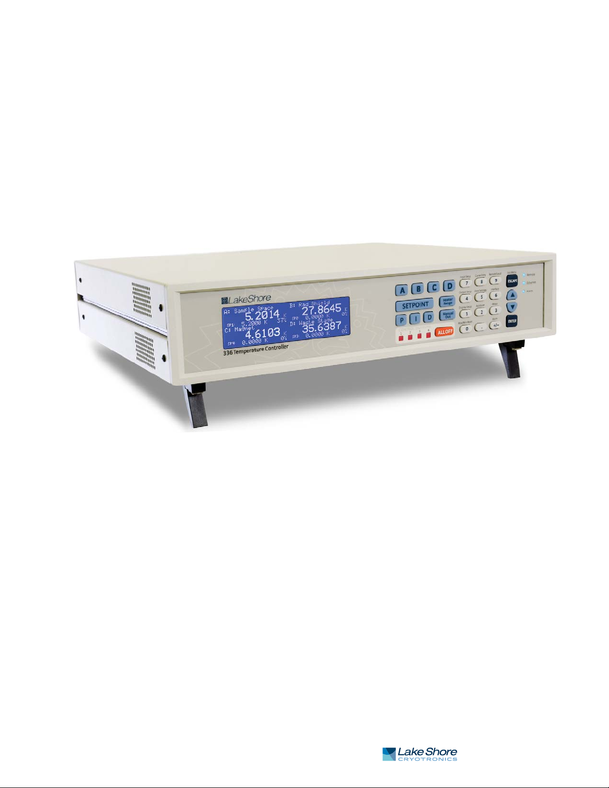
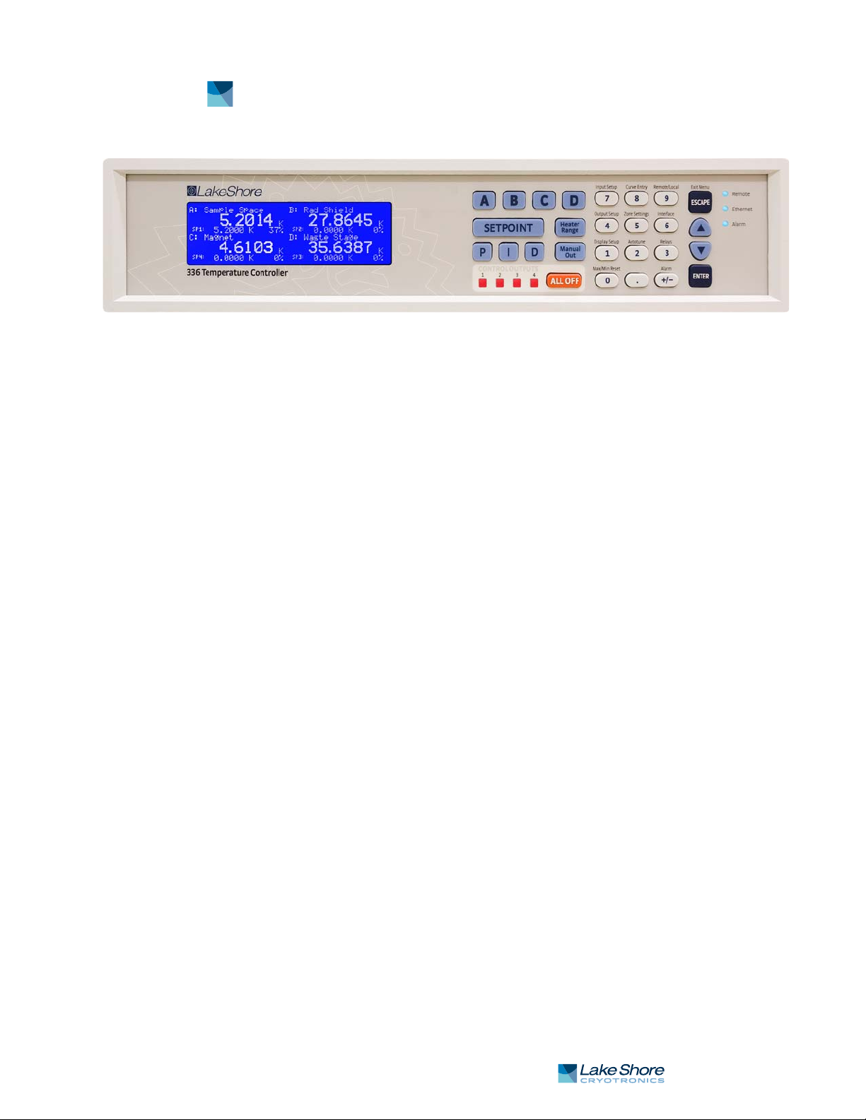
FIGURE 1-1 Model 336 front view
1.1 Product Description
Features:
D Operates down to 300 mK with appropriate NTC RTD sensors
D Four sensor inputs and four independent control outputs
D Two PID control loops: 100 W and 50 W into a 50 ) or 25 ) load
D Autotuning automatically collects PID parameters
D Automatically switch sensor inputs using zones to allow continuous measure-
ment and control from 300 mK to 1505 K
D Custom display setup allows you to label each sensor input
D Ethernet, USB, and IEEE-488 interfaces
D Supports diode, RTD, and thermocouple temperature sensors
D Sensor excitation current reversal eliminates thermal EMF errors for
resistance sensors
D
±10 V analog voltage outputs, alarms, and relays
The first of a new generation of innovative temperature measurement and control
solutions by Lake Shore, the Model 336 temperature controller comes standard
equipped with many advanced features promised to deliver the functionality and
reliable service you’ve come to expect from the world leader in cryogenic thermometry. The Model 336 is the only temperature controller available with four sensor
inputs, four control outputs, and 150 W of low noise heater power. Two independent
heater outputs providing 100 W and 50 W can be associated with any of the four sensor inputs and programmed for closed loop temperature control in proportional-integral-derivative (PID) mode. The improved autotuning feature of the Model 336 can be
used to automatically collect PID parameters, so you spend less time tuning your controller and more time conducting experiments.
The Model 336 supports the industry’s most advanced line of cryogenic temperature
sensors as manufactured by Lake Shore, including diodes, resistance temperature
detectors (RTDs) and thermocouples. The controller’s zone tuning feature allows you
to measure and control temperatures seamlessly from 300 mK to over 1,500 K by
automatically switching temperature sensor inputs when your temperature range
goes beyond the usable range of a given sensor. You’ll never again have to be concerned with temperature sensor over or under errors and measurement continuity
issues. Alarms, relays, and ±10 V analog voltage outputs are available to help automate secondary control functions.
| www.lakeshore.com

2 cHAPTER 1: Introduction
Another innovative first from Lake Shore, the ability to custom label sensor inputs
eliminates the guesswork in remembering or determining the location to which a
sensor input is associated. As we strive to maintain increasingly demanding workloads, ease of use and the ability to stay connected from anywhere in the world are
critical attributes. With standard Ethernet, USB, and IEEE-488 interfaces and an intuitive menu structure and logic, the Model 336 was designed with efficiency, reliable
connectivity, and ease of use in mind. While you may need to leave your lab, Ethernet
ensures you’ll always be connected to your experiments. The new intuitive front
panel layout and keypad logic, bright graphic display, and LED indicators enhance the
user friendly front panel interface of the Model 336.
In many applications, the unparalleled feature set of the Model 336 allows you to
replace several instruments with one, saving time, money and valuable laboratory
space. Delivering more feedback, tighter control, and faster cycle times, the
Model 336 keeps up with increasingly complex temperature measurement and control applications. It is the ideal solution for general purpose to advanced laboratory
applications. Put the Model 336 temperature controller to use in your lab and let it
take control of your measurement environment.
1.1.1 Sensor Inputs
The Model 336 offers 4 standard sensor inputs that are compatible with diode and
RTD temperature sensors. The field installable Model 3060 thermocouple input
option provides support for up to two thermocouple inputs by adding thermocouple
functionality to inputs C and D.
Sensor inputs feature a high-resolution 24-bit analog-to-digital converter; each
input has its own current source, providing fast settling times. All four sensor inputs
are optically isolated from other circuits to reduce noise and to provide repeatable
sensor measurements. Current reversal eliminates thermal electromotive force
(EMF) errors in resistance sensors. Nine excitation currents facilitate temperature
measurement and control down to 300 mK using appropriate negative temperature
coefficient (NTC) RTDs. Autorange mode automatically scales excitation current in
NTC RTDs to reduce self heating at low temperatures as sensor resistance changes by
many orders of magnitude. Temperatures down to 1.4 K can be measured and controlled using silicon or GaAlAs diodes. Software selects the appropriate excitation current and signal gain levels when the sensor type is entered via the instrument front
panel. The unique zone setting feature automatically switches sensor inputs,
enabling you to measure temperatures from 300 mK to over 1,500 K without interrupting your experiment.
The Model 336 includes standard temperature sensor response curves for silicon
diodes, platinum RTDs, ruthenium oxide RTDs, and thermocouples. Non-volatile
memory can also store up to 39 200-point CalCurves for Lake Shore calibrated temperature sensors or user curves. A built-in SoftCal™ algorithm can be used to generate curves for silicon diodes and platinum RTDs that can be stored as user curves.
Temperature sensor calibration data can be easily uploaded and manipulated using
the Lake Shore curve handler software.
1.1.2 Temperature Control
Model 336 Temperature Controller
Providing a total of 150 W of heater power, the Model 336 is the most powerful temperature controller available. Delivering very clean heater power, it precisely controls
temperature throughout the full scale temperature range for excellent measurement
reliability, efficiency, and throughput. Two independent PID control outputs supplying 100 W and 50 W of heater power can be associated with any of the four standard
sensor inputs. Precise control output is calculated based on your temperature setpoint and feedback from the control sensor. Wide tuning parameters accommodate
most cryogenic cooling systems and many high-temperature ovens commonly used
in laboratories. PID values can be manually set for fine control, or the improved
1 . 1 . 3 I n t e r f a c e 3
autotuning feature can automate the tuning process. Autotune collects PID parameters and provides information to help build zone tables. The setpoint ramp feature
provides smooth, continuous setpoint changes and predictable setpoint approaches
without the worry of overshoot or excessive settling times. When combined with the
zone setting feature, which enables automatic switching of sensor inputs and scales
current excitation through 10 different preloaded temperature zones, the Model 336
provides continuous measurement and control from 300 mK to 1505 K.
Control outputs 1 and 2 are variable DC current sources referenced to chassis ground.
Output 1 can provide 100 W of continuous power to a 25 ) load or 50 W to a 50 ) or
25 ) load. Output 2 provides 50 W to 25 ) or 50 ) heater loads. Outputs 3 and 4 are
variable DC voltage source outputs providing two ±10 V analog outputs. When not in
use to extend the temperature controller heater power, these outputs can function as
manually controlled voltage sources.
Temperature limit settings for inputs are provided as a safeguard against system
damage. Each input is assigned a temperature limit, and if any input exceeds that
limit, all control channels are automatically disabled.
1.1.3 Interface
The Model 336 is standard equipped with Ethernet, universal serial bus (USB) and
parallel (IEEE-488) interfaces. In addition to gathering data, nearly every function of
the instrument can be controlled through a computer interface. You can download
the Lake Shore curve handler software to your computer to easily enter and manipulate sensor calibration curves for storage in the instrument’s non-volatile memory.
Ethernet provides the ability to access and monitor instrument activities via the
internet from anywhere in the world. The USB interface emulates an RS-232 serial
port at a fixed 57,600 baud rate, but with the physical plug-ins of a USB. It also allows
you to download firmware upgrades, ensuring the most current firmware version is
loaded into your instrument without having to physically change anything.
Each sensor input has a high and low alarm that offer latching and non-latching operation. The 2 relays can be used in conjunction with the alarms to alert you of a fault
condition and perform simple on/off control. Relays can be assigned to any alarm or
operated manually.
The ±10 V analog voltage outputs on outputs 3 and 4 can be configured to send a voltage proportional to temperature to a strip chart recorder or data acquisition system.
You may select the scale and data sent to the output, including temperature or
sensor units.
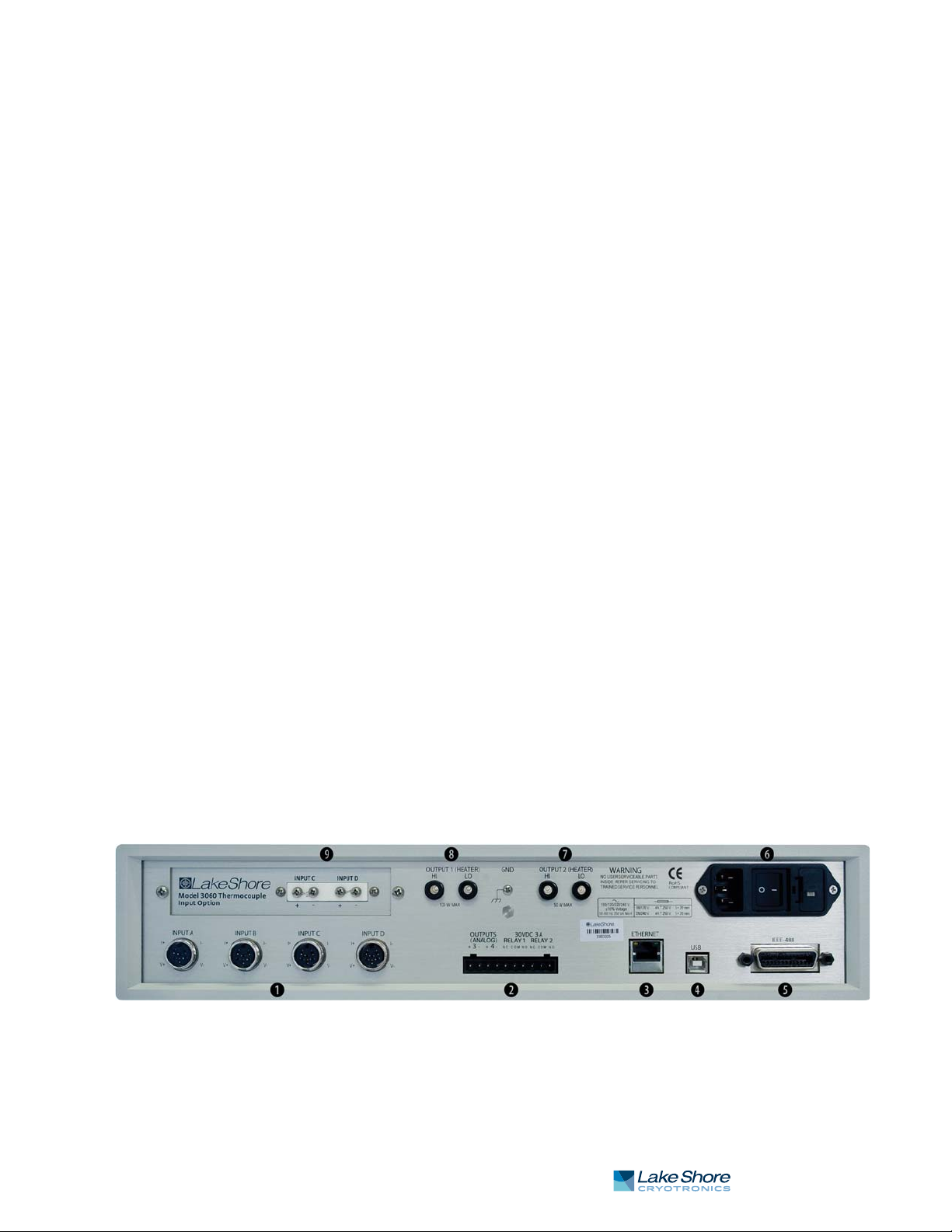
bSensor input connectors
cTer mi na l b lo ck
dEthernetinterface
e USB interface
FIGURE 1-2 Model 336 rear panel
f IEEE-488 interface
g Line input assembly
h Output 2 heater
i Output 1 heater
j Thermocouple
option inputs
| www.lakeshore.com
4 cHAPTER 1: Introduction
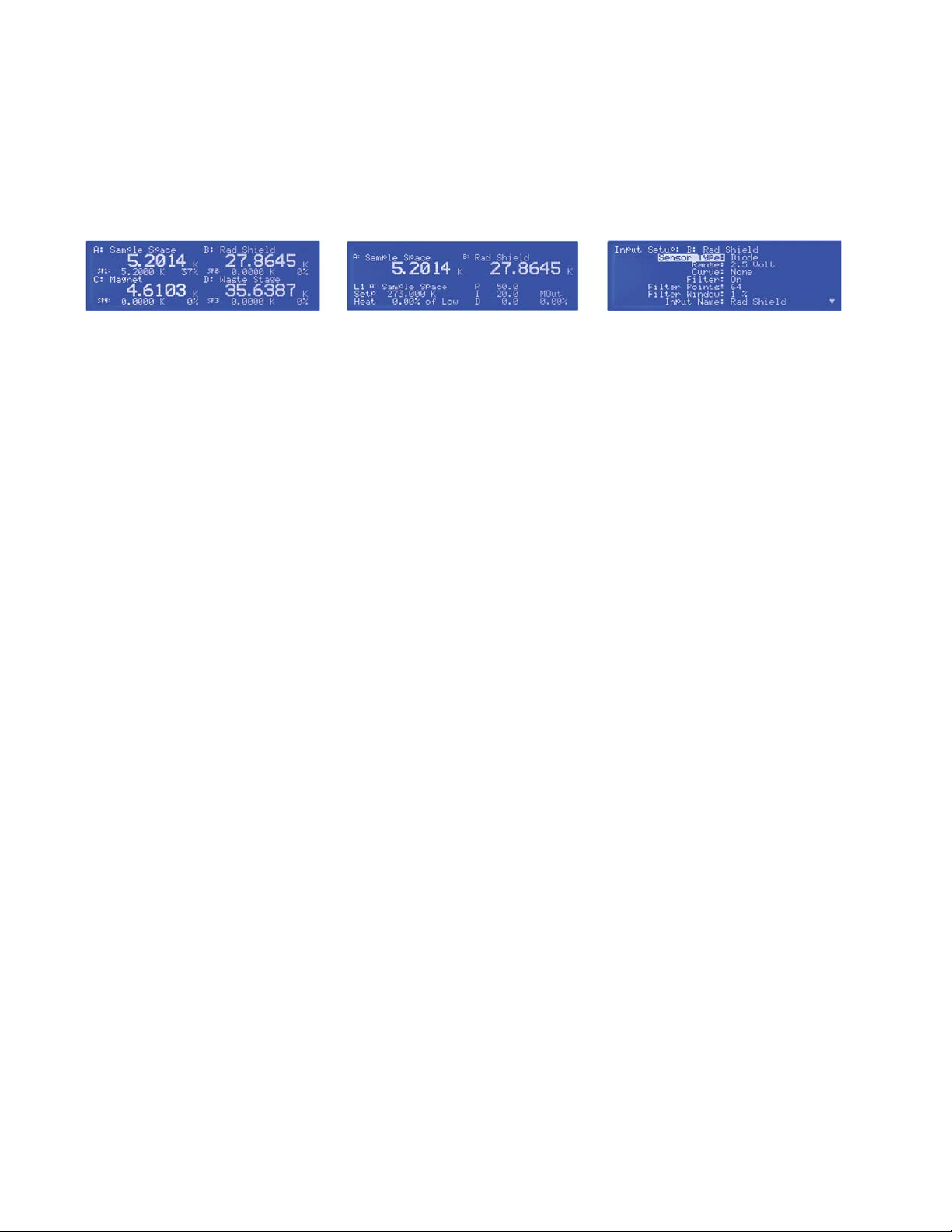
1.1.4 Configurable Display
1.1.5 Three Option Cards
The Model 336 offers a bright, graphic liquid crystal display with an LED backlight
that simultaneously displays up to 8 readings. You can show all 4 loops, or if you need
to monitor 1 input, you can display just that one in greater detail. Or you can custom
configure each display location to suit your experiment. Data from any input can be
assigned to any of the locations, and your choice of temperature or sensor units can
be displayed. For added convenience, you can also custom label each sensor input,
eliminating the guesswork in remembering or determining the location to which a
sensor input is associated.
FIGURE 1-3 Displays showing four loop mode, input display mode and custom display mode
Field installable input option cards can expand your sensor selection to include silicon diodes (like DT-670), capacitance sensors or thermocouples. Once installed, the
option input can be selected and named from the front panel like any other input
type. These option cards further expand the application versatility of the Model 336
temperature controller by allowing specialized sensors to be switched in and out to
achieve specific measurement objectives.
For example, addition of the thermocouple input option enables continuous measurement to 1000 K and above. Alternatively, the capacitance sensor option card
enables a magnetics-impervious capacitance temperature sensor to be temporarily
switched in for elimination of magneto-resistive effects while taking low temperature sample measurements under high or changing fields. The 4-channel scanner
option card enables use of additional sensors for supplemental monitoring.
1.2 Sensor Selection
Silicon diodes are the best choice for general cryogenic use from 1.4 K to above room
temperature. Diodes are economical to use because they follow a standard curve and
are interchangeable in many applications. They are not suitable for use in ionizing
radiation or magnetic fields.
Cernox™ thin-film RTDs offer high sensitivity and low magnetic field-induced errors
over the 0.3 K to 420 K temperature range. Cernox sensors require calibration.
Platinum RTDs offer high uniform sensitivity from 30 K to over 800 K. With excellent
reproducibility, they are useful as thermometry standards. They follow a standard
curveabove 70 K and are interchangeable in many applications.
Model 336 Temperature Controller

1 . 2 S e n s o r S e l e c t i o n 5
Model Useful Range Magnetic Field Use
Diodes
(3062)
Positive Temperature
Coefficient RTDs
Negative
Temperature
Coefficient RTDs
Capacitance
3061
Thermocouples
3060
1
Non-HT version maximum temperature: 325 K
2
Low temperature limited by input resistance range
3
Low temperature specified with self-heating error: " 5 mK
Silicon Diode DT-670-SD 1.4 K to 500 K T # 60 K & B " 3 T
Silicon Diode DT-670E-BR 30 K to 500 K T# 60 K & B " 3 T
Silicon Diode DT-414 1.4 K to 375 K T # 60 K & B " 3 T
Silicon Diode DT-421 1.4 K to 325 K T # 60 K & B " 3 T
Silicon Diode DT-470-SD 1.4 K to 500 K T # 60 K & B " 3 T
Silicon Diode DT-471-SD 10 K to 500 K T # 60 K & B " 3 T
GaAlAs Diode TG-120-P 1.4 K to 325 K T > 4.2 K & B " 5 T
GaAlAs Diode TG-120-PL 1.4 K to 325 K T > 4.2 K & B " 5 T
GaAlAs Diode TG-120-SD 1.4 K to 500 K T > 4.2 K & B " 5 T
100 ) Platinum PT-102/3 14 K to 873 K T > 40 K & B " 2.5 T
100 ) Platinum PT-111 14 K to 673 K T > 40 K & B " 2.5 T
Rhodium-Iron RF-800-4 1.4 K to 500 K T > 77 K & B " 8 T
Rhodium-Iron RF-100T/U 1.4 K to 325 K T > 77 K & B " 8 T
Cernox™ CX-1010 0.3 K to 325 K
Cernox™ CX-1030-HT 0.3 K to 420 K
Cernox™ CX-1050-HT 1.4 K to 420 K
Cernox™ CX-1070-HT 4 K to 420 K
Cernox™ CX-1080-HT 20 K to 420 K
1
T > 2 K & B " 19 T
1, 3
1
1
1
T > 2 K & B " 19 T
T > 2 K & B " 19 T
T > 2 K & B " 19 T
T > 2 K & B " 19 T
Germanium GR-200A-100 0.3 K to 100 K Not recommended
Germanium GR-200A-250 0.5 K to 100 K Not recommended
Germanium GR-200A/B-500 1.4 K to 100 K Not recommended
Germanium GR-200A/B-1000 1.4 K to 100 K Not recommended
Germanium GR-200A/B-1500 1.4 K to 100 K Not recommended
Germanium GR-200A/B-2500 1.4 K to 100 K Not recommended
Carbon-Glass CG R-1-500 1.4 K to 325 K T > 2 K & B " 19 T
Carbon-Glass CGR-1-1000 1.7 K to 325 K
Carbon-Glass CGR-1-2000 2 K to 325 K
Rox™ RX-102 0.3 K to 40 K
2
T > 2 K & B " 19 T
2
3
T > 2 K & B " 19 T
T > 2 K & B " 10 T
Rox™ RX-103 1.4 K to 40 K T > 2 K & B " 10 T
Rox™ RX-202 0.3 K to 40 K
3
T > 2 K & B " 10 T
CS-501 1.4 K to 290 K T>4.2 K & B " 18.7 T
Type K 9006-006 3.2 K to 1505 K Not recommended
Type E 9006-004 3.2 K to 934 K Not recommended
Chromel-AuFe 0.07% 9006-002 1.2 K to 610 K Not recommended
TABLE 1-1 Sensor temperature range
| www.lakeshore.com

6 cHAPTER 1: Introduction
Example
Lake Shore
Tem p er a t u r e
Sensor
1.4 K
77 K
300 K
500 K
1.4 K
77 K
300 K
475 K
1.4 K
77 K
300 K
475 K
Silicon Diode
Silicon Diode
GaAlAs Diode
DT-670-CO-13
with 1.4H
calibration
DT-470-SD-13
with 1.4H
calibration
TG-120-SD
with 1.4H
calibration
30 K
100 ) Platinum RTD
500 ) Full Scale
PT-103 with 14J
calibration
77 K
300 K
500 K
0.3 K
0.5 K
4.2 K
300 K
1.4 K
6
4.2 K
77 K
420 K
0.35 K
1.4 K
4.2 K
100 K
1.8 K
4.2 K
10 K
100 K
1.4 K
4.2 K
77 K
300 K
0.5 K
1.4 K
4.2 K
40 K
Cernox™
Cernox™
Germanium
Germanium
Carbon-Glass
Rox™
CX-1010-SD
with 0.3L
calibration
CX-1050-SD-HT
with 1.4M
calibration
GR-300-AA
with 0.3D
calibration
GR-1400-AA
with 1.4D
calibration
CGR-1-500
with 1.4L
calibration
RX-102A-AA
with 0.3B
calibration
4.2
Capacitance CS-501
77
200
Thermocouple
50 mV
Typ e K
3060
4
Typical sensor sensitivities were taken from representative calibrations for the sensor listed
5
Control stability of the electronics only, in an ideal thermal system
6
Non-HT version maximum temperature: 325 K
7
Accuracy specification does not include errors from room temperature compensation
75 K
300 K
600 K
1505 K
Nominal
Resistance/
Volta ge
1.664 V
1.028 V
0.5597 V
0.0907 V
1.6981 V
1.0203 V
0.5189 V
0.0906 V
5.391 V
1.422 V
0.8978 V
0.3778 V
3.660 )
20.38 )
110.35 )
185.668 )
2322.4 )
1248.2 )
277.32 )
30.392 )
26566 )
3507.2 )
205.67 )
45.03)
18225 )
449 )
94 )
2.7 )
15288 )
1689 )
253 )
2.8 )
103900 )
584.6 )
14.33 )
8.55 )
3701 )
2005 )
1370 )
1049 )
6.0 nF
9.1 nF
19.2 nF
-5862.9 µV
1075.3 µV
13325 µV
49998.3 µV
Typ i ca l
Sensor
Sensitivity
-12.49 mV/K
-1.73 mV/K
-2.3 mV/K
-2.12 mV/K
-13.1 mV/K
-1.92 mV/K
-2.4 mV/K
-2.22 mV/K
-97.5 mV/K
-1.24 mV/K
-2.85 mV/K
-3.15 mV/K
0.191 )/K
0.423 )/K
0.387 )/K
0.378 )/K
-10785 )/K
-2665.2 )/K
-32.209 )/K
-0.0654 )/K
-48449 )/K
-1120.8 )/K
-2.4116 )/K
-0.0829 )/K
-193453 )/K
-581 )/K
-26.6 )/K
-0.024 )/K
-26868 )/K
-862 )/K
-62.0 )/K
-0.021 )/K
-520000 )/K
-422.3 )/K
-0.098 )/K
-0.0094 )/K
-5478 )/K
-667 )/K
-80.3 )/K
-1.06 )/K
27 pF/K
52 pF/K
174 pF/K
15.6 µV/K
40.6 µV/K
41.7 µV/K
36.006 µV/K
TABLE 1-2 Typical sensor performance
Measurement
Resolution :
Temperature
4
Equivalents
0.8 mK
5.8 mK
4.4 mK
4.7 mK
0.8 mK
5.2 mK
4.2 mK
4.5 mK
0.2 mK
16 mK
7 mK
6.4 mK
1.1 mK
0.5 mK
5.2mK
5.3 mK
8.5 µK
26 µK
140 µK
23 mK
20 µK
196 µK
1.9 mK
18 mK
4 µK
41 µK
56µK
6.3 mK
28 µK
91 µK
73 µK
7.1 mK
13 µK
63 µK
4.6 mK
16 mK
41 µK
128µK
902 µK
62 mK
74 mK
39 mK
12 mK
26 mK
10 mK
10 mK
11 mK
Electronic
Accuracy:
Temperature
Equivalents
±13 mK
±76 mK
±47 mK
±40 mK
±13 mK
±69 mK
±45 mK
±38 mK
±7 mK
±180 mK
±60 mK
±38 mK
±13 mK
±10 mK
±39 mK
±60 mK
±0.1 mK
±0.2 mK
±3.8 mK
±339 mK
±0.3 mK
±2.1 mK
±38 mK
±338 mK
±48 µK
±481 µK
±1.8 mK
±152 mK
±302 µK
±900 µK
±1.8 mK
±177 mK
±0.1 mK
±0.8 mK
±108 mK
±760 mK
±0.5 mK
±1.4 mK
±8 mK
±500 mK
NA
7
±0.25 K
7
±0.038 K
7
±0.184 K
7
±0.73 K
Temperature
Accuracy
including
Electronic
Accuracy,
CalCurve and
Calibrated Sensor
±25 mK
±98 mK
±79 mK
±90 mK
±25 mK
±91 mK
±77 mK
±88 mK
±19 mK
±202 mK
±92 mK
±88 mK
±23 mK
±22 mK
±62 mK
±106 mK
±3.6 mK
±4.7 mK
±8.8 mK
±414 mK
±5.3 mK
±7.1 mK
±54 mK
±403 mK
±4.2 mK
±4.7 mK
±6.8 mK
±175mK
±4.5 mK
±5.1 mK
±6.8 mK
±200 mK
±4.1 mK
±4.8 mK
±133 mK
±865 mK
±5 mK
±6.4 mK
±24 mK
±537 K
Calibration not
available from
Lake Shore
Calibration not
available from
Lake Shore
Electronic
Control
5
Stability
Temperature
Equivalents
±1.6 mK
±11.6 mK
±8.8 mK
±9.4 mK
±1.6 mK
±10.4 mK
±8.4 mK
±9 mK
±0.4 mK
±32 mK
±14 mK
±13 mK
±2.2 mK
±1.0 mK
±10.4 mK
±10.6 mK
±17 µK
±52 µK
±280 µK
±46 mK
±40 µK
±392 µK
±3.8 mK
±36 mK
±8 µK
±82 µK
±112 µK
±12.6 mK
±56 µK
±182 µK
±146 µK
±14.2 mK
±26 µK
±126 µK
±9.2 mK
±32 mK
±82 µK
±256 µK
±1.8 mK
±124 mK
±14.8 mK
±7.7 mK
±23 mK
±52 mK
±20 mK
±20 mK
±22 mK
:
Model 336 Temperature Controller

1.3 Model 336 Specifications
1.3.1 Input Specifications
1 . 3 M o d e l 3 3 6 S p e c i f i c a t i o n s 7
Standa rd
inputs and
scanner option
Model 3062
Diode Negative 0 V to 2.5 V 10 µA ±0.05%
PTC RTD Positive 0 ) to 10 ) 1 mA
NTC RTD
Sensor
Tem p e r a -
ture Coeffi-
Input Range Excitation
Current
cient
Negative 0 V to 10 V 10 µA ±0.05%
0 ) to 30 ) 1 mA
0 ) to 100 ) 1 mA
0 ) to 300 ) 1 mA
0 ) to 1 k) 1 mA
0 ) to 3 k) 1 mA
0 ) to 10 k) 1 mA
Negative 0 ) to 10 ) 1 mA
Display
Resoluti on
9,10
9,10
11
11
11
11
11
11
11
11
100 µV 10 µV ±80 µV ±0.005%
100 µV 20 µV ±320 µV ±0.01%
0.1 m) 0.2 m) ±0.002 )
0.1 m) 0.2 m) ±0.002 )
1 m) 2 m) ±0.004 )
1 m) 2 m) ±0.004 )
10 m) 20 m) ±0.04 )
10 m) 20 m) ±0.04 )
100 m) 200 m) ±0.4 )
0.1 m) 0.2 m) ±0.002) ±0.06%
10 mV
0 ) to 30 ) 300 µA
0 ) to 100 ) 100 µA
0 ) to 300 ) 30µA
0 ) to 1 k) 10 µA
0 ) to 3 k) 3 µA
0 ) to 10 k) 1 µA
0 ) to 30 k) 300 nA
0) to 100 k) 100 nA
8
Control stability of the electronics only, in ideal thermal system
9
Current source error has negligible effect on measurement accuracy
10
Diode input excitation can be set to 1 mA
11
Current source error is removed during calibration
12
Accuracy specification does not include errors from room temperature compensation
11
11
11
11
11
11
11
11
0.1 m) 0.2 m) ±0.002 ) ±0.06%
1 m) 1 m) ±0.01 ) ±0.04%
1 m) 2 m) ±0 .01 ) ±0.04% of
10 m) 10 m) +0.002%
10 m) 20 m) +0.002%
100 m) 100 m) +0.0 02%
100 m) 200 m) +0.0 02%
1 ) 1) +0.005% of rdg ±10.0 ) ±0.04%
TABLE 1-3 Input specifications
Measurement
Resoluti on
of rdg
of rdg
of rdg
of rdg
Electronic
Accuracy
(at 25 °C)
of rdg
of rdg
±0.01% of rdg
±0.01% of rdg
±0.01% of rdg
±0.01% of rdg
±0.02% of rdg
±0.02% of rdg
±0.02% of rdg
of rdg
of rdg
of rdg
rdg
±0.1 ) ±0.04%
of rdg
±0.1 ) ±0.04%
of rdg
±1.0 ) ±0.04%
of rdg
±2.0 ) ±0.04%
of rdg
of rdg
Measurement Temperature
Coefficient
Electronic
Control Stability
(10 µV + 0.0005% of rdg)/ °C ±20 µV
(20 µV + 0.0005% of rdg)/ °C ±40 µV
(0.01 m) + 0.001% of rdg)/°C ±0.4 m)
(0.03 m) + 0.001% of rdg)/°C ±0.4 m)
(0.1 m) + 0.001% of rdg)/°C ±4 m)
(0.3 m) + 0.001% of rdg)/°C ±4 m)
(1 m) + 0.001% of rdg)/°C ±40 m)
(3 m) + 0.001% of rdg)/°C ±40 m)
(10 m) + 0.001% of rdg)/°C ±400 m)
(0.01 m) + 0.001% of rdg)/°C ±0.3 m)
(0.03 m) + 0.001% of rdg)/°C ±0.9 m)
(0.1 m) + 0.001% of rdg)/°C ±3 m)
(0.3 m) + 0.001% of rdg)/°C ±9 m)
(1 m) + 0.001% of rdg)/°C ±30 m) ±0.004%
of rdg
(3 m) + 0.001% of rdg)/°C ±90 m) ±0.004%
of rdg
(10 m) + 0.001% of rdg)/°C ±300 m)
±0.004% of rdg
(30 m) + 0.001% of rdg)/°C ±900 m)
±0.004% of rdg
(100 m) + 0.001% of rdg)/°C ±3 ) ±0.01% of
rdg
8
| www.lakeshore.com

8 cHAPTER 1: Introduction
Thermocouple
option
Model 3060
Thermocouple
3060
13
Control stability of the electronics only, in ideal thermal system
Sensor
Tem p e r a -
ture Coeffi-
cient
Positive ±50 mV NA 0.1 µV 0.4µV ±1 µV ±0.05%
Input Range Excitation
Current
TABLE 1-4 Thermocouple option input specifications
Capacitance
option
Model 3061
Capacitance
3061
14
Control stability of the electronics only, in ideal thermal system
Sensor
Tem p e r a -
ture Coeffi-
cient
Positive or
negative
Input Range Excitation
Current
0.1 nF to 15 nF 3.496 kHz 1 mA
square wave
1 nF to 150 nF 3.496 kHz 10 mA
square wave
TABLE 1-5 Capacitance option input specifications
1.3.2 Sensor Input Configuration
Measurement
type
Excitation
Supported sensors
Standard curves
Input connector 6-pin DIN
Display
Resoluti on
Display
Resoluti on
0.1 pF 0.05 pF ±50 pF ±0.1%
1 pF 0.5 pF ±50 pF ±0.1%
RTDs: 100 ) Platinum (option), 1000 ) Plat-
Carbon-Glass, Cernox™, and Rox™
DT-470, DT-670, DT-500-D, DT-500-E1,
PT-100, PT-1000, RX-102A, RX-202A
Measurement
Resoluti on
Measurement
Resoluti on
Diode/RTD Thermocouple
4-lead differential
Constant current with
current reversal for RTDs
Diodes: Silicon, GaAlAs
inum, Germanium,
Electronic
Accuracy
(at 25 °C)
of rdg
Electronic
Accuracy
(at 25 °C)
of rdg
of rdg
TABLE 1-6 Sensor input configuration
Measurement Temperature
Coefficient
(0.1 µV + 0.001% of rdg)/°C ±0.8µV
12
Measurement Temperature
Coefficient
2.5 pF/°C 0.1 pF
5 pF/°C 1 pF
2-lead differential, room
temperature compensated
NA
Most thermocouple types
Type E, Type K, Type T, AuFe
0.07% vs. Cr, AuFe 0.03% vs. CR
Screw terminals in a ceramic
isothermal block
Electronic
Control
Stability
Electronic
Control
Stability
13
14
1.3.3 Thermometry
Model 336 Temperature Controller
Number of inputs 4 (8 with Model 3062)
Input configuration Inputs can be configured from the front panel to accept any of the
supported input types. Thermocouple and capacitance inputs require
an optional input card that can be installed in the field.
Supported option cards Thermocouple (3060), capacitance (3061), or scanner (3062)
Option slots 1
Isolation Sensor inputs optically isolated from other circuits but not each other
A/D resolution 24-bit
Input accuracy Sensor dependent, refer to Input Specifications table
Measurement resolution Sensor depend ent, refer to Input Specifications table
Maximum update rate 10 rdg/s on each input , 5 rdg/s when configured as 100 k) NTC RTD
with reversal on
Maximum update rate (scanner) The maximum update rate for a scanned input is 10 rdg/s distributed among
the enabled channels. Any channel configured as 100 k) RTD with reversal on
changes the update rate for the channel to 5 rdg/s
Autorange Automatically selects appropriate NTC RTD or PTC RTD range
User curves Room for 39 200-point CalCurves™ or user curves
SoftCal™ Improves accuracy of DT-470 diode to ±0.25 K from 30 K to 375 K; improves
accuracy of platinum RTDs to ±0.25 K from 70 K to 325 K; stored as user curves
Math Maximum and minimum
Filter Averages 2 to 64 input readings

1 . 3 . 4 C o n t r o l 9
1.3.4 Control
There are 4 control outputs.
1.3.4.1 Heater Outputs (Outputs 1 and 2)
Control type Closed loop digital PID with manual heater output or open loop
Update rate 10/s
Tuning Autotune (one loop at a time), PID, PID zones
Control stability Sensor dependent, see Input Specifications table
PID control settings
Proportional (gain) 0 to 1000 with 0.1 setting resolution
Integral (reset) 1 to 1000 (1000/s) with 0.1 settin g resolution
Derivative (rate) 1 to 200% with 1% resolution
Manual output 0 to 100% with 0.01% setting resolution
Zone control 10 temperature zones with P, I, D, manual heater out,
heater ra nge, control cha nnel, ramp rate
Setpoint rampin 0.1 K/min to 100 K/min
25 ) setting 50 ) setting
Typ e Variable DC current source
D/A res olution 16-bit
Max power 100 W 50 W
Max current 2 A 1 A
Compliance voltage 50 V 50 V
Heater load for max power 25 ) 50 )
Heater load range 10 ) to 100 )
Ranges 3 (decade steps in power)
Heater noise 0.12 µA RMS (dominated by line frequency and its harmonics)
Grounding Output referenced to chassis ground
Heater connector Dual banana
Safety limits Curve temperature, power up heater off, short circuit protection
TABLE 1-7 Output 1
25 ) setting 50 ) setting
Typ e Variable DC current source
D/A res olution 16-bit
Max power 50 W 50 W
Max current 1.41 A 1 A
Compliance voltage 35.4 V 50 V
Heater load for max power 25 ) 50 )
Heater load range 10 ) to 100 )
Ranges 3 (decade steps in power)
Heater noise 0.12 µA RMS (dominated by line frequency and its harmonics)
Grounding Output referenced to chassis ground
Heater connector Dual banana
Safety limits Curve temperature, power up heater off, short circuit protection
TABLE 1-8 Output 2
| www.lakeshore.com

10 cHAPTER 1: Introduction
1.3.4.2 Unpowered Analog Outputs (Outputs 3 and 4)
Control type
Tuning Autotune (one loop at a time), PID, PID zones
Control stability Sensor dependedn, see Input Specifications table
PID control settings
Proportional (gain) 0 to 1000 with 0.1 setting resolution
Integral (reset) 1 to 1000 (100 0/s) with 0.1 setting resolution
Derivative (rate) 1 to 200% with 1% resolution
Manual output 0 to 100% with 0.01% setting resolution
Zone co ntrol
Setpoint ramping 0.1 K/min to 100 K/min
Warm up heater mode settings
Warm up percentage 0 to 100% with 1% resolution
Warm up mode Continuous control or auto-off
Monitor Out settings
Scale User selected
Data source Temperature or sensor units
Settings Input, source, top of scale, bottom of scale or manual
Typ e Variable DC voltage source
Update rate 10/s
Range ±10 V
Resoluti on 16-bit, 0.3 mV
Accuracy ±2.5 mV
Noise 0.3 mV RMS
Minimum load resistance 1 k) (short-circuit protected)
Connector Detachable terminal block
Closed loop PID, PID zones, warm up heater mode, manual output or
Monitor Out
10 temperature zones with P, I, D, manual heater out, heater range,
control channel, ramp rate
1.3.5 Front Panel
Display 8-line by 40-character (240 × 64 pixel) graphic LCD display module with
LED backlight
Number of reading displays 1 to 8
Display units K, °C, V, mV, )
Reading s ource Temperature, sensor units, max, and min
Display update rate 2 rdg/s
Temperature display resolution 0.0001° from 0° to 99.9999°, 0.001° from 100° to 999.999°,
0.01° above 1000°
Sensor units display resolution Sensor dependent, to 6 digits
Other displays Input name, setpoint, heater range, heater output, and PID
Setpoint setting resolution Same as display resolution (actual resolution is sensor dependent)
Heater output display Numeric display in percent of full scale for power or current
Heater output resolution 0.01%
Display annunciators Control input, alarm, tuning
LED annunciators Remote, Ethernet status, alarm, control outputs
Keypa d 27-key silicone elastomer keypad
Front panel features Front panel curve entry, display contrast control, and keypad lock-out
Model 336 Temperature Controller

1 . 3 . 6 I n t e r f a c e 11
1.3.6 Interface
IEEE-488.2
Capabilities SH1, AH1, T5, L4, SR1, RL1, PP0, DC1, DT0, C0, E1
Reading r ate To 10 rdg/s on each input
Software support LabVIEW™ driver (contact Lake Shore for availability)
USB
Function Emulates a standard RS-232 serial port
Baud Rate 57,600
Connector B- type USB connector
Reading r ate To 10 rdg/s on each input
Software support LabVIEW™ driver (contact Lake Shore for availability)
Ethernet
Function TCP/IP web interface, curve handler, configuration backup,
chart recorder
Connector RJ-45
Reading r ate To 10 rdg/s on each input
Software support LabVIEW™ driver (contact Lake Shore for availability)
Alarms
Number 4, high and low for each input
Data source Temperature or sensor units
Settings Source, high setpoint, low setpoint, deadband, latching or
non-latching, audible on/off, and visible on/off
Actuators Display annunciator, beeper, and relays
Relays
Number 2
Contacts Normally open (NO), normally closed (NC), and common (C)
Contact rating 30 VDC at 3 A
Operation Activate relays on high, low, or both alarms for any input, or
manual mode
Connector Detachable terminal block
1.3.7 General
Ambient temperature 15 °C to 35 °C at rated accuracy;
5 °C to 40 °C at reduced accuracy
Power requirement 100, 120, 220, 240, VAC, ±10%, 50 or 60 Hz, 250 VA
Size 435 mm W × 89 mm H × 368 mm D
(17 in × 3.5 in × 14.5 in), f ull rack
Weight 7.6 kg (16.8 lb)
Approval CE mark
| www.lakeshore.com

12 cHAPTER 1: Introduction
1.4 Safety Summary and Symbols
Observe these general safety precautions during all phases of instrument operation,
service, and repair. Failure to comply with these precautions or with specific warnings elsewhere in this manual violates safety standards of design, manufacture, and
intended instrument use. Lake Shore Cryotronics, Inc. assumes no liability for Customer failure to comply with these requirements.
The Model 336 protects the operator and surrounding area from electric shock or
burn, mechanical hazards, excessive temperature, and spread of fire from the instrument. Environmental conditions outside of the conditions below may pose a hazard
to the operator and surrounding area.
D Indoor use
D Altitude to 2000 m
D Temperature for safe operation: 5 °C to 40 °C
D Maximum relative humidity: 80% for temperature up to 31 °C decreasing
linearly to 50% at 40 °C
D Power supply voltage fluctuations not to exceed ±10% of the nominal voltage
D Overvoltage category II
D Pollution degree 2
Ground the Instrument
To minimize shock hazard, the instrument is equipped with a 3-conductor AC power
cable. Plug the power cable into an approved 3-contact electrical outlet or use a
3-contact adapter with the grounding wire (green) firmly connected to an electrical
ground (safety ground) at the power outlet. The power jack and mating plug of the
power cable meet Underwriters Laboratories (UL) and International Electrotechnical
Commission (IEC) safety standards.
Ventilation
The instrument has ventilation holes in its side covers. Do not block these holes when
the instrument is operating.
Do Not Operate in an Explosive Atmosphere
Do not operate the instrument in the presence of flammable gases or fumes. Operation of any electrical instrument in such an environment constitutes a definite safety
hazard.
Keep Away from Live Circuits
Operating personnel must not remove instrument covers. Refer component replacement and internal adjustments to qualified maintenance personnel. Do not replace
components with power cable connected. To avoid injuries, always disconnect power
and discharge circuits before touching them.
Do Not Substitute Parts or Modify Instrument
Do not install substitute parts or perform any unauthorized modification to the
instrument. Return the instrument to an authorized Lake Shore Cryotronics, Inc. representative for service and repair to ensure that safety features are maintained.
Cleaning
Do not submerge instrument. Clean only with a damp cloth and mild detergent. Exterior only.
Model 336 Temperature Controller
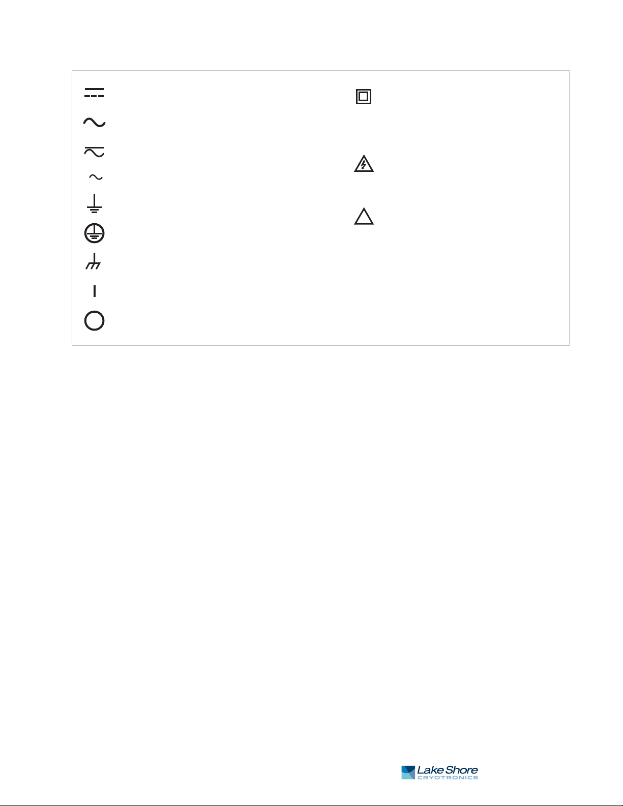
1 . 4 S a f e t y S u m m a r y a n d S y m b o l s 13
!
Direct current (power line)
Equipment protected throughout
by double insulation or reinforces
insulation (equivalent to Class II of
IEC 536—see Annex H)
CAUTION: High voltages; danger of
electric shock; background color:
yellow; symbol and outline: black
CAUTION or WARNING: See
instrument documentation;
background color: yellow;
symbol and outline: black
Off (supply)
On (supply)
Frame or chassis terminal
Protective conductor terminal
Earth (ground) terminal
3
Three-phase alternating current (power line)
Alternating or direct current (power line)
Alternating current (power line)
FIGURE 1-4 Safety symbols
| www.lakeshore.com

14 cHAPTER 1: Introduction
Model 336 Temperature Controller

2.2.1 Temperature Range 15
Chapter 2: Cooling System Design
and Temperature Control
2.1 General
2.2 Temperature Sensor Selection
2.2.1 Temperature Range
Selecting the proper cryostat or cooling source is probably the most important decision in designing a temperature control system. The cooling source defines minimum
temperature, cool-down time, and cooling power. Information on choosing a cooling
source is beyond the scope of this manual. This chapter provides information on how
to get the best temperature measurement and control from cooling sources with
proper setup including sensor and heater installation.
This section attempts to answer some of the basic questions concerning temperature
sensor selection. Additional useful information on temperature sensor selection is
available in the Lake Shore Temperature Measurement and Control Catalog. The catalog has a large reference section that includes sensor characteristics and sensor
selection criteria.
You must consider several important sensor parameters when choosing a sensor. The
first is experimental temperature range. Some sensors can be damaged by temperatures that are either too high or too low. Manufacturer recommendations should
always be followed.
Sensor sensitivity changes with temperature and can limit the useful range of a sensor. It is important not to specify a range larger than necessary. If you perform an
experiment at liquid helium temperature, a very high sensitivity is needed for good
measurement resolution at that temperature. That same resolution may not be
required to monitor warm up to room temperature. Two different sensors may be
required to tightly cover the range from base temperature to room temperature, but
lowering the resolution requirement on warm up may allow a less expensive,
1 sensor solution.
Another thing to consider when choosing a temperature sensor is that instruments
like the Model 336 are not able to read some sensors over their entire temperature
range. Lake Shore sells calibrated sensors that operate down to 20 millikelvin (mK),
but the Model 336 is limited to above 300 mK in its standard configuration.
2.2.2 Sensor Sensitivity
Temperature sensor sensitivity is a measure of how much a sensor signal changes
when the temperature changes. It is an important sensor characteristic because so
many measurement parameters are related to it. Resolution, accuracy, noise floor,
and even control stability depend on sensitivity. Many sensors have different sensitivities at different temperatures. For example, a platinum sensor has good sensitivity at
higher temperatures, but it has limited use below 30 K because its sensitivity drops
sharply. It is difficult to determine if a sensor has adequate sensitivity over the experimental temperature range. This manual has specifications (section 1.3) that include
sensor sensitivity translated into temperature resolution and accuracy at different
points. This is typical sensor response and can be used as a guide when choosing a
sensor to be used with the Model 336.
| www.lakeshore.com

16 cHAPTER 2: Cooling System Design and Temperature Control
2.2.3 Environmental Conditions
2.2.4 Measurement Accuracy
The experimental environment is also important when choosing a sensor. Environmental factors such as high vacuum, magnetic field, corrosive chemicals, or even
radiation can limit the use of some types of sensors. Lake Shore has devoted much
time to developing sensor packages that withstand the temperatures, vacuum levels,
and bonding materials found in typical cryogenic cooling systems.
Experiments done in magnetic fields are very common. Field dependence of temperature sensors is an important selection criteria for sensors used in these experiments.
This manual briefly qualifies the field dependence of most common sensors in the
specifications (section 1.3). Detailed field dependence tables are included in the
Lake Shore Temperature Measurement and Control Catalog. When available, specific
data on other environmental factors is also included in the catalog.
Temperature measurements have several sources of uncertainty that reduce accuracy. Be sure to account for errors induced by both the sensor and the instrumentation when computing accuracy. The instrument has measurement error in reading
the sensor signal, and error in calculating a temperature using a temperature
response curve. Error results when the sensor is compared to a calibration standard
and the temperature response of a sensor will shift with time and with repeated thermal cycling (from very cold temperatures to room temperature). Instrument and sensor manufacturers specify these errors, but there are things you can do to maintain
good accuracy. For example, choose a sensor that has good sensitivity in the most
critical temperature range, as sensitivity can minimize the effect of most error
sources. Install the sensor properly following guidelines in section 2.4. Calibrate the
sensor and instrument periodically, or in some other way null the time dependent
errors. Use a sensor calibration that is appropriate for the accuracy requirement.
2.2.5 Sensor Package
2.3 Sensor Calibrations
There are different packages for the various types of sensors. Some types of sensors
can even be purchased as bare chips without any package. A sensor package generally
determines its size, thermal and electrical contact to the outside, and sometimes limits temperature range. When different packages are available for a sensor, you should
consider the mounting surface for the sensor and how the leads will be thermally
anchored when choosing.
It can sometimes be confusing to choose the right sensor, get it calibrated, translate
the calibration data into a temperature response curve that the Model 336 can
understand, and then load the curve into the instrument. Lake Shore provides a variety of calibration services to fit different accuracy requirements and budgets.
Best Precision calibration All sensors can be calibrated over various temperature ranges.
Lake Shore has defined calibration ranges available
for each sensor type.
Better SoftCal™ An abbreviated calibration (2-point: 77 K and 305 K; 3-point: 4.2 K,
77 K, and 305 K; or 3-point: 77 K, 305 K, and 480 K), which is available for 400 Series silicon diodes and platinum sensors
Good Sensors using standard curves Silicon diodes follow standard curves
Platinum resistors follow standard curves
Ruthenium oxide (Rox™) resistors follow standard curves
Thermocouples follow standard curves
GaAlAs diode, carbon-glass, Cernox™, germanium, and rhodium-
iron sensors can be purchased uncalibrated, but must be calibrated
to accurately read in temperature units
TABLE 2-1 Sensor diode sensor calibrations
Model 336 Temperature Controller

2.3.1 Precision Calibration 17
2.3.1 Precision Calibration
To calibrate, Lake Shore compares a sensor with an unknown temperature response
to an accepted standard. Lake Shore temperature standards are traceable to the
U.S. National Institute of Standards and Testing (NIST) or the National Physical Laboratory in Great Britain. These standards allow Lake Shore to calibrate sensors from
20 mK to above room temperature. Calibrated sensors are more expensive than
uncalibrated sensors of the same type because of the labor, cryogen use, and capitol
equipment used in the process.
Precision calibration provides the most accurate temperature sensors available from
Lake Shore. Uncertainty from sensor calibration is almost always smaller than the
error contributed by the Model 336. The Lake Shore Temperature Measurement and
Control Catalog has complete accuracy specifications for calibrated sensors.
Calibrated sensors include the measured test data printed and plotted, the coefficients of a Chebychev polynomial that have been fitted to the data, and two tables of
data points to be used as interpolation tables. Both interpolation tables are optimized to allow accurate temperature conversion. The smaller table, called a breakpoint interpolation table, is sized to fit into instruments like the Model 336 where it is
called a temperature response curve.
It is important to look at instrument specifications before ordering calibrated sensors. A calibrated sensor is required when a sensor does not follow a standard curve if
you wish to display in temperature. Otherwise the Model 336 will operate in sensor
units like ohms or volts. The Model 336 may not work over the full temperature range
of some sensors. The standard inputs in are limited to operation above 300 mK even
with sensors that can be calibrated to 20 mK.
2.3.2 SoftCal™
2.3.3 Sensors Using Standard Curves
2.3.4 Curve Handler™
SoftCal™ is a good solution for applications that do not require the accuracy of a precision calibration. The SoftCal™ algorithm uses the well-behaved nature of sensors
that follow a standard curve to improve the accuracy of individual sensors. A few
known temperature points are required to perform SoftCal™. The Model 336 can also
perform a SoftCal™ calibration. You need to provide one, two, or three known temperature reference points. The range and accuracy of the calibration is based on these
points (section 5.10).
Lake Shore offers two or three point SoftCal™ calibrated sensors that include both
the large interpolation table and the smaller breakpoint interpolation table for 400
series diode and Platinum sensors.
Some types of sensors behave in a very predictable manner and a standard temperature response curve can be created for them. Standard curves are a convenient and
inexpensive way to get reasonable temperature accuracy. Sensors that have a standard curve are often used when interchangeability is important. Some individual sensors are selected for their ability to match a published standard curve, but in general
these sensors do not provide the accuracy of a calibrated sensor. For convenience, the
Model 336 has several standard curves included in firmware.
Lake Shore provides a software application, called Curve Handler™, which makes
loading temperature curves into the Model 336 a very simple process. The program
can copy curves from properly formatted files into the Model 336 user curve locations. You can also use it to read curves from the Model 336 and save them to files.
Lake Shore calibrated sensors are provided with a CD containing all the proper formats to load curves using the Curve Handler™ software program.
| www.lakeshore.com

18 cHAPTER 2: Cooling System Design and Temperature Control
There are two versions of the Curve Handler™ application. The fully featured version
is a 32-bit Microsoft Windows™ application that must be installed on a Windows™
PC. This version works with the IEEE-488 and USB computer interfaces on the
Model 336, and allows you to manipulate the temperature curves directly in the program window. This version will also work with all existing Lake Shore temperature
controller and temperature monitor instruments. The Windows™ version of the
Curve Handler™ application is available, free of charge, from the Lake Shore website
at www.lakeshore.com.
The second version of Curve Handler™ is written in the Java™ programming language
and is available through the Ethernet web interface on the Model 336. This version
allows you to copy curves from files to the Model 336, and vice versa, but it does not
allow manipulation of curve data and only works using the Ethernet interface. Refer
to section 6.4.4 for details on connecting to the web interface and opening the
embedded Curve Handler™ application.
2.4 Sensor Installation
2.4.1 Mounting Materials
2.4.2 Sensor Location
This section highlights some of the important elements of proper sensor installation.
For more detailed information, Lake Shore sensors are shipped with installation
instructions that cover that specific sensor type and package. The Lake Shore Temperature Measurement and Control Catalog includes an installation section as well.
To further help you properly install sensors, Lake Shore offers a line of cryogenic
accessories. Many of the materials discussed are available through Lake Shore and
can be ordered with sensors or instruments.
Choosing appropriate mounting materials is very important in a cryogenic environment. The high vacuum used to insulate cryostats is one consideration. Materials
used in these applications should have a low vapor pressure so they do not evaporate
or out-gas and spoil the vacuum insulation. Metals and ceramics do not have this
problem, but greases and varnishes must be checked. Another consideration is the
wide extremes in temperature most sensors are exposed to. The linear expansion
coefficient of materials becomes important when temperature changes are large.
Never try to permanently bond materials with linear expansion coefficients that differ by more than three. Use a flexible mounting scheme or the parts will break apart,
potentially damaging them. The thermal expansion or contraction of rigid clamps or
holders could crush fragile samples or sensors that do not have the same coefficient.
Thermal conductivity is a property of materials that can change with temperature. Do
not assume that a thermal anchor grease that works well at room temperature and
above will do the same job at low temperatures.
Finding a good place to mount a sensor in an already crowded cryostat is never easy.
There are fewer problems if the entire load and sample holder are at the same temperature. Unfortunately, this not the case in many systems. Temperature gradients
(differences in temperature) exist because there is seldom perfect balance between
the cooling source and heat sources. Even in a well-controlled system, unwanted heat
sources like thermal radiation and heat conducting through mounting structures can
cause gradients. For best accuracy, position sensors near the sample, so that little or
no heat flows between the sample and sensor. This may not, however, be the best
location for temperature control as discussed below.
2.4.3 Thermal Conductivity
Model 336 Temperature Controller
The ability of heat to flow through a material is called thermal conductivity. Good
thermal conductivity is important in any part of a cryogenic system that is intended
to be the same temperature. Copper and aluminum are examples of metals that have
good thermal conductivity, while stainless steel does not. Non-metallic, electricallyinsulating materials like alumina oxide and similar ceramics have good thermal con-
 Loading...