

Lakeshore 330 User Manual

r
User’s Manual
Model 330
Model 330
Model 330Model 330
Autotuning
Methods and apparatus disclosed and described herein have been developed solely on company funds of Lake Shore Cryotronics, Inc.
No government or other contractual support or relationship whatsoever has existed which in any way affects or mitigates proprietary
rights of Lake Shore Cryotronics, Inc. in these developments. Methods and apparatus disclosed herein may be subject to U.S. Patents
existing or applied for. Lake Shore Cryotronics, Inc. reserves the right to add, improve, modify, or withdraw functions, design
modifications, or products at any time without notice. Lake Shore shall not be liable for errors contained herein or for incidental or
consequential damages in connection with furnishing, performance, or use of this material.
Model 330-1X – Silicon Diode
Model 330-2X – Platinum Resistor
Model 330-3X – GaAlAs Diode
Model 330-4X – Thermocouple
Model 330-5X – Thermocouple
Lake Shore Cryotronics, Inc.
575 McCorkle Blvd.
Westerville, Ohio 43082-8888 USA
E-Mail Addresses:
sales@lakeshore.com
service@lakeshore.com
Visit Our Website:
www.lakeshore.com
Fax: (614) 891-1392
Telephone: (614) 891-2243
Temperature Controlle
Includes Coverage For:
Rev. 1.3 P/N 119-009 15 November 2000

Lake Shore Model 330 Autotuning Temperature Controller User’s Manual
LIMITED WARRANTY
Lake Shore Cryotronics, Inc. (henceforth Lake Shore), the manufacturer, warrants this product to be free from defects in
material or workmanship for a period of 12 months from the date of shipment. During the warranty period, under
authorized return of instruments or component parts to Lake Shore freight prepaid, the company will repair, or at its
option replace, any part found to be defective in material or workmanship, without charge to the owner for parts, service
labor or associated customary return shipping cost. Replacement or repaired parts will be warranted for only the
unexpired portion of the original warranty or 90 days (whichever is greater).
All products are thoroughly tested and calibrated to published specifications prior to shipment. Calibration Certifications
are offered for 6 month periods only. Where such documentation must be updated, a re-certification service is offered by
Lake Shore at a reasonable cost.
LIMITATION OF WARRANTY
This warranty does not apply to defects resulting from improper installation, product modifications made by others without
Lake Shore’s express written consent, or from misuse of any product or part. This warranty also does not apply to fuses,
software, non-rechargeable batteries, or problems arising from normal wear or failure to follow instructions.
This warranty is in lieu of any other warranties, expressed or implied, including merchantability, or fitness for a particular
purpose, which are expressly excluded. The owner agrees that Lake Shore's liability with respect to this product shall be
set forth in this warranty, and incidental or consequential damages are expressly excluded.
CERTIFICATION
Lake Shore certifies that this product has been inspected and tested in accordance with its published specifications and
that this product met its published specifications at the time of shipment. The accuracy and calibration of this product at
the time of shipment are traceable to the United States National Institute of Standards and Technology (NIST); formerly
known as the National Bureau of Standards (NBS).
FIRMWARE LIMITATIONS
Lake Shore has worked to ensure that the Model 330 firmware is as free of errors as possible, and that the results you
obtain from the instrument are accurate and reliable. However, as with any computer-based software, the possibility of
errors exists.
In any important research, as when using any laboratory equipment, results should be carefully examined and rechecked
before final conclusions are drawn. Neither Lake Shore nor anyone else involved in the creation or production of this
firmware can pay for loss of time, inconvenience, loss of use of the product, or property damage caused by this product
or its failure to work, or any other incidental or consequential damages. Use of our product implies that you understand
the Lake Shore license agreement and statement of limited warranty.
FIRMWARE LICENSE AGREEMENT
The firmware in this instrument is protected by United States copyright law and international treaty provisions. To
maintain the warranty, the code contained in the firmware must not be modified. Any changes made to the code is at the
user’s risk. Lake Shore will assume no responsibility for damage or errors incurred as result of any changes made to the
firmware.
Under the terms of this agreement you may only use the Model 330 firmware as physically installed in the instrument.
Archival copies are strictly forbidden. You may not decompile, disassemble, or reverse engineer the firmware. If you
suspect there are problems with the firmware, return the instrument to Lake Shore for repair under the terms of the
Limited Warranty specified above. Any unauthorized duplication or use of the Model 330 firmware in whole or in part, in
print, or in any other storage and retrieval system is forbidden.
TRADEMARK ACKNOWLEDGMENT
Many manufacturers and sellers claim designations used to distinguish their products as trademarks. Where those
designations appear in this manual and Lake Shore was aware of a trademark claim, they appear with initial capital
letters and the ™ or
Apiezon® is a trademark of Biddle Instruments.
CalCurve™, Carbon-Glass™, Cernox™, Duo-Twist™, Quad-Lead™, Quad-Twist™,
and SoftCal™ are trademarks of Lake Shore Cryotronics, Inc.
Chromel™ and Alumel™ are trademarks of Hoskins Manufacturing Company.
Cryo-Gloves
Formvar™ is a trademark of Monsanto Chemical Company.
MS-DOS
NI-488.2™ is a trademark of National Instruments.
Stycast
Teflon
®
and Windows/95/98/NT/2000® are trademarks of Microsoft Corporation.
®
is a trademark of Emerson & Cuming.
®
is a trademark of DuPont De Nemours.
®
symbol.
®
is a trademark of Tempshield.
Copyright © 1994 – 2000 by Lake Shore Cryotronics, Inc. All rights reserved. No portion of this manual may be
reproduced, stored in a retrieval system, or transmitted, in any form or by any means, electronic, mechanical,
photocopying, recording, or otherwise, without the express written permission of Lake Shore.
A

Lake Shore Model 330 Autotuning Temperature Controller User’s Manual
Declaration of Conformity
We: Lake Shore Cryotronics, Inc.
575 McCorkle Blvd.
Westerville, OH 43082-8888 USA
hereby declare that the equipment specified conforms to the following
Directives and Standards:
Application of Council directives: 73/23/EEC
89/336/EEC
Standard to which Conformity is declared: EN55022
EN50082-1
EN61010-1
Model Number: 330
Signature Date
John M. Swartz
Printed Name
President
Position
B

Lake Shore Model 330 Autotuning Temperature Controller User’s Manual
Electromagnetic Compatibility (EMC) for the Model 330 Temperature Controller
Electromagnetic Compatibility (EMC) of electronic equipment is a growing concern worldwide.
Emissions of and immunity to electromagnetic interference is now part of the design and manufacture of
most electronics. To qualify for the CE mark, the Model 330 meets or exceeds the generic requirements
of the European EMC directive 89/336/EEC. The instrument was tested under normal operating
conditions with sensor and interface cables attached. If the installation and operating instructions in the
User's Manual are followed, there should be no degradation in EMC performance.
Pay special attention to instrument cabling. Improperly installed cabling may defeat even the best EMC
protection. For the best performance from any precision instrument, follow the grounding and shielding
instructions in the User's Manual. In addition, the installer of the Model 330 should consider the
following:
• Leave no unused or unterminated cables attached to the instrument.
• Make cable runs as short and direct as possible.
• Do not tightly bundle cables that carry different types of signals.
• Add the clamp-on ferrite filter (part number 109-053) included with the connector kit to the serial
interface cable near the instrument rear panel when that interface is used.
C

Lake Shore Model 330 Autotuning Temperature Controller User’s Manual
TABLE OF CONTENTS
Chapter/Paragraph Title Page
1 INTRODUCTION ....................................................................................................................................1-1
1.0 General................................................................................................................................1-1
1.1 Model 330 Temperature Controller Description ..................................................................1-2
1.2 Control Fundamentals and Autotune................................................................................... 1-5
1.3 Precision Calibration Options ..............................................................................................1-6
1.4 Electrostatic Discharge........................................................................................................1-6
1.4.1 Identification of Electrostatic Discharge Sensitive Components ......................................1-6
1.4.2 Handling Electrostatic Discharge Sensitive Components ................................................1-6
1.5 Handling Liquid Helium and Liquid Nitrogen........................................................................ 1-7
1.5.1 Handling Cryogenic Storage Dewars ...............................................................................1-7
1.5.2 Liquid Helium and Nitrogen Safety Precautions ............................................................... 1-7
1.5.3 Recommended First Aid...................................................................................................1-7
1.6 Safety Summary .................................................................................................................. 1-8
1.7 Safety Symbols....................................................................................................................1-8
2 INSTALLATION......................................................................................................................................2-1
2.0 General................................................................................................................................2-1
2.1 Inspection and Unpacking ...................................................................................................2-1
2.2 Repackaging For Shipment .................................................................................................2-1
2.3 Definition of Rear Panel Connections.................................................................................. 2-2
2.4 Sensor Input Settings ..........................................................................................................2-3
2.5 Grounding and Shielding .....................................................................................................2-3
2.6 Sensor Installation ...............................................................................................................2-4
2.6.1 Diode (Model 330-1X) and Platinum (Model 330-2X) Connections ................................. 2-4
2.6.1.1 Two-Lead Versus Four-Lead Measurements ...............................................................2-4
2.6.1.2 Heat Sinking Sensor Leads .......................................................................................... 2-5
2.6.1.3 Sensor Mounting ........................................................................................................... 2-5
2.6.1.4 Measurement Errors Due to AC Noise .........................................................................2-6
2.6.2 Thermocouple (Model 330-4X) Connections ...................................................................2-6
2.6.2.1 Thermocouple Compensation....................................................................................... 2-6
2.6.2.2 Thermocouple Wire Types at Cryogenic Temperatures ...............................................2-6
2.6.3 Sensor Input Error Messages .......................................................................................... 2-7
2.7 Sensor Curve Selection.......................................................................................................2-7
2.8 Precision Calibration Option ................................................................................................2-8
2.9 Heater Setup .......................................................................................................................2-9
2.10 Rack Mounting.....................................................................................................................2-9
2.11 Power Up.............................................................................................................................2-9
2.11.1 Power Up Sequence ........................................................................................................2-9
2.11.2 Power Up (PUP) Configuration ......................................................................................2-10
2.11.3 Power Up Errors............................................................................................................. 2-10
3 OPERATION...........................................................................................................................................3-1
3.0 General................................................................................................................................3-1
3.1 Definition of Front Panel Controls........................................................................................ 3-1
3.1.1 Front Panel Keypad Definitions........................................................................................ 3-1
3.1.2 Front Panel LED Display ..................................................................................................3-2
3.2 Thermometry Functions ...................................................................................................... 3-2
3.2.1 Input Type ........................................................................................................................3-3
3.2.2 Channel ............................................................................................................................ 3-3
3.2.3 Units .................................................................................................................................3-3
3.2.4 Thermocouple Temperature Compensation (Model 330-4X Only) .................................. 3-3
3.2.5 Display Filter.....................................................................................................................3-4
3.2.6 Curve................................................................................................................................3-4
Table of Contents i

Lake Shore Model 330 Autotuning Temperature Controller User’s Manual
Chapter/Paragraph Title Page
3.2.7 SoftCal ............................................................................................................................. 3-5
3.2.7.1 SoftCal Errors ............................................................................................................... 3-5
3.2.7.2 Customer-Performed SoftCal ....................................................................................... 3-6
3.2.7.3 Entering Voltage Values from a Lake Shore SoftCal Report........................................ 3-6
3.3 Control Functions................................................................................................................ 3-8
3.3.1 Heater .............................................................................................................................. 3-8
3.3.2 Setpoint and Control ........................................................................................................ 3-8
3.3.2.1 Voltage Resolution (Models 321-1X, -3X, & -4X Only)................................................. 3-9
3.3.2.2 Resistance Resolution (Model 330-2X Only)................................................................ 3-9
3.3.3 Ramp ............................................................................................................................... 3-9
3.3.4 AutoTune ......................................................................................................................... 3-9
3.3.4.1 Initial Values of PID Parameters in Autotuning Mode................................................. 3-10
3.3.4.2 Minimum Overshoot ................................................................................................... 3-10
3.3.4.3 Minimum Time To Setpoint ........................................................................................ 3-10
3.3.4.4 Gain Only.................................................................................................................... 3-10
3.3.5 Manual Control Settings (PID) ....................................................................................... 3-10
3.3.5.1 Setting Gain (Proportional) ......................................................................................... 3-10
3.3.5.2 Setting Reset (Integral)............................................................................................... 3-10
3.3.5.3 Setting Rate (Derivative)............................................................................................. 3-11
3.3.5.4 Effect of Temperature on Tuning Parameters ............................................................ 3-11
3.3.6 Zone Setting................................................................................................................... 3-11
3.4 Interface and Miscellaneous Functions............................................................................. 3-13
3.4.1 Baud............................................................................................................................... 3-13
3.4.2 Address.......................................................................................................................... 3-13
3.4.3 Local .............................................................................................................................. 3-13
3.4.4 Instrument Reset and Factory Default Settings ............................................................. 3-13
3.4.5 Power Up (PUP) Configuration...................................................................................... 3-14
3.5 Thermocouple Controller Operation (Model 330-4X Only) ............................................... 3-15
3.5.1 Sensor Attachment ........................................................................................................ 3-15
3.5.2 Thermocouple Curve Selection ..................................................................................... 3-15
3.5.3 Thermocouple Compensation From Front Panel .......................................................... 3-15
3.5.4 Thermocouple Compensation From Remote Interface ................................................. 3-15
3.5.5 Internal Offset Adjustment ............................................................................................. 3-15
3.5.6 Curve Format................................................................................................................. 3-15
4 REMOTE OPERATION.......................................................................................................................... 4-1
4.0 General ............................................................................................................................... 4-1
4.1 IEEE-488 Interface.............................................................................................................. 4-1
4.1.1 IEEE-488 Interface Settings ............................................................................................ 4-1
4.1.2 IEEE-488 Command Structure ........................................................................................ 4-1
4.1.2.1 Bus Control Commands ............................................................................................... 4-2
4.1.2.2 Common Commands ................................................................................................... 4-2
4.1.2.3 Interface and Device Specific Commands ................................................................... 4-2
4.1.3 Status Registers .............................................................................................................. 4-2
4.1.3.1 Status Byte Register and Service Request Enable Register ........................................ 4-2
4.1.3.2 Standard Event Status Register and Standard Event Enable Register ........................ 4-3
4.1.4 Example IEEE Setup and Program ................................................................................. 4-4
4.1.4.1 GPIB Board Installation ................................................................................................ 4-4
4.1.4.2 Run the Example QuickBasic Program ........................................................................ 4-4
4.1.5 Notes On Using the IEEE Interface ................................................................................. 4-4
4.2 Serial I/O Interface .............................................................................................................. 4-7
4.2.1 Serial Interface Hardware Configuration.......................................................................... 4-8
4.2.2 Sample BASIC Serial Interface Program ......................................................................... 4-8
4.2.3 Notes On Using The Serial Interface ............................................................................... 4-8
ii Table of Contents

Lake Shore Model 330 Autotuning Temperature Controller User’s Manual
Chapter/Paragraph Title Page
4.3 IEEE-488/Serial Interface Command Summary................................................................ 4-10
4.3.1 Command List Structure ................................................................................................4-10
4.3.2 Common Commands .....................................................................................................4-11
4.3.3 Interface Commands ...................................................................................................... 4-13
4.3.4 Display Commands ........................................................................................................ 4-14
4.3.5 Control Process Commands ..........................................................................................4-16
4.3.6 Curve Commands ..........................................................................................................4-19
4.4 User Curve Loading Program............................................................................................ 4-23
5 SERVICE AND CALIBRATION ..............................................................................................................5-1
5.0 General................................................................................................................................5-1
5.1 General Maintenance Precautions ......................................................................................5-1
5.2 Changing Power Setting and Fuse Rating...........................................................................5-1
5.3 Rear Panel Connector Definitions .......................................................................................5-2
5.4 IEEE-488 Interface Connector............................................................................................. 5-3
5.5 Optional Serial Interface Cable and Adapters .....................................................................5-4
5.6 Top of Enclosure Remove and Replace Procedure ............................................................5-5
5.7 Operating Software EPROM and Precision Option NOVRAM Replacement ...................... 5-5
5.8 Error Messages ...................................................................................................................5-6
5.9 Changing Sensor Input Type............................................................................................... 5-6
5.10 Calibration (Diode/Platinum Input).......................................................................................5-7
5.11 Model 330-4X (Thermocouple) Calibration .........................................................................5-9
5.12 Model 330-4X (Thermocouple) Internal Offset Adjustment.................................................5-9
6 OPTIONS AND ACCESSORIES ............................................................................................................6-1
6.0 General................................................................................................................................6-1
6.1 Models .................................................................................................................................6-1
6.2 Options ................................................................................................................................ 6-1
6.2.1 Model 330-51 Option........................................................................................................6-2
6.3 Accessories ......................................................................................................................... 6-3
APPENDIX A – CURVE TABLES ................................................................................................................ A-1
APPENDIX B – APPLICATION NOTES ...................................................................................................... B-1
B1.0 General............................................................................................................................... B-1
ALPHABETICAL INDEX ...................................................................................................................... INDEX-1
Table of Contents iii

Lake Shore Model 330 Autotuning Temperature Controller User’s Manual
LIST OF ILLUSTRATIONS
Figure No. Title Page
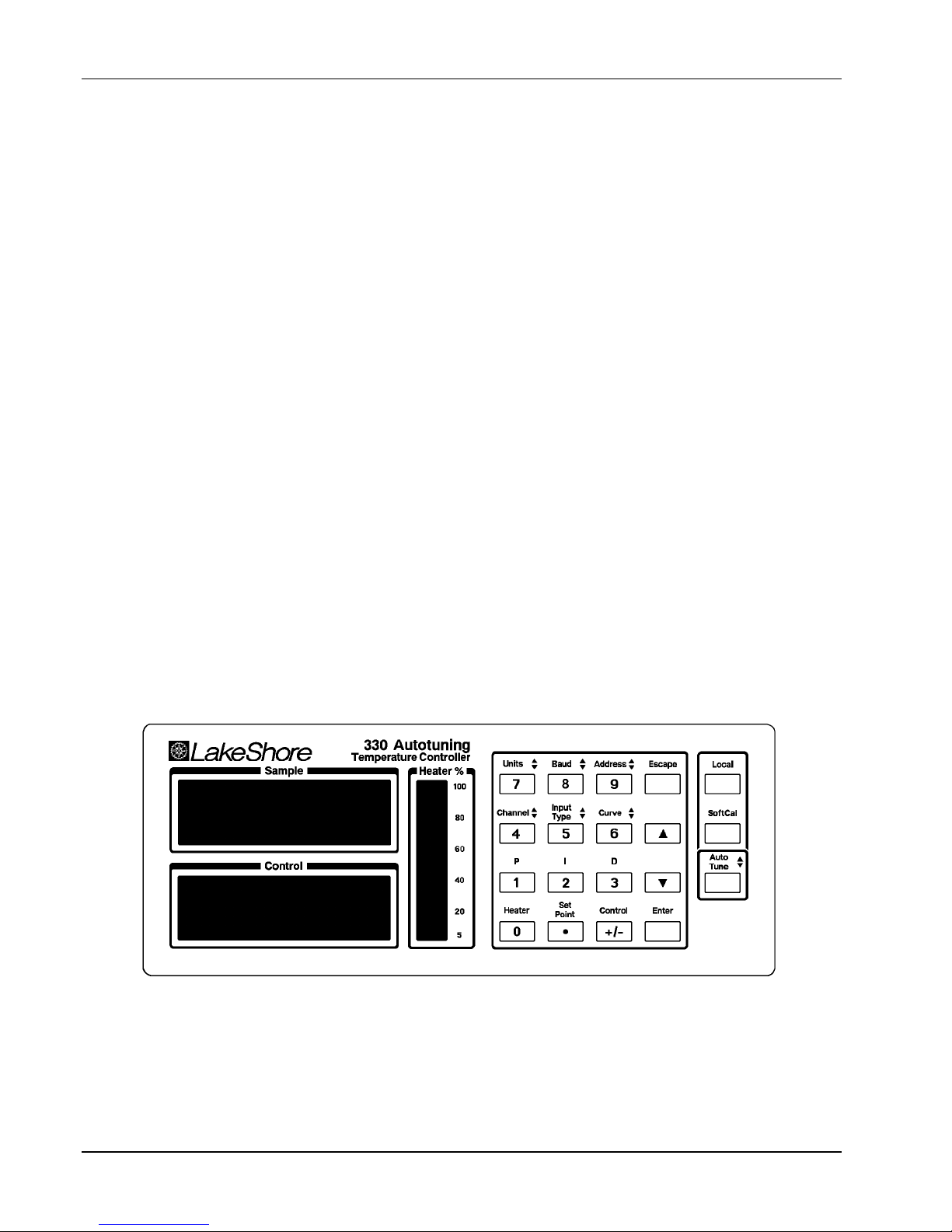
1-1 Model 330 Temperature Controller Front Panel .............................................................................. 1-2
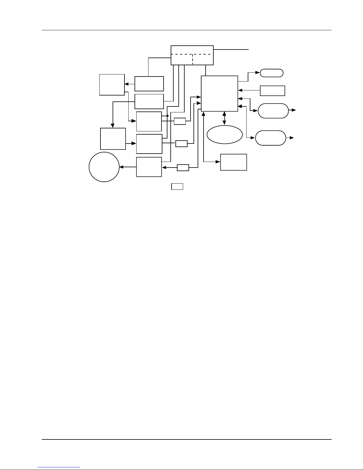
1-2 Model 330 Block Diagram ................................................................................................................ 1-5
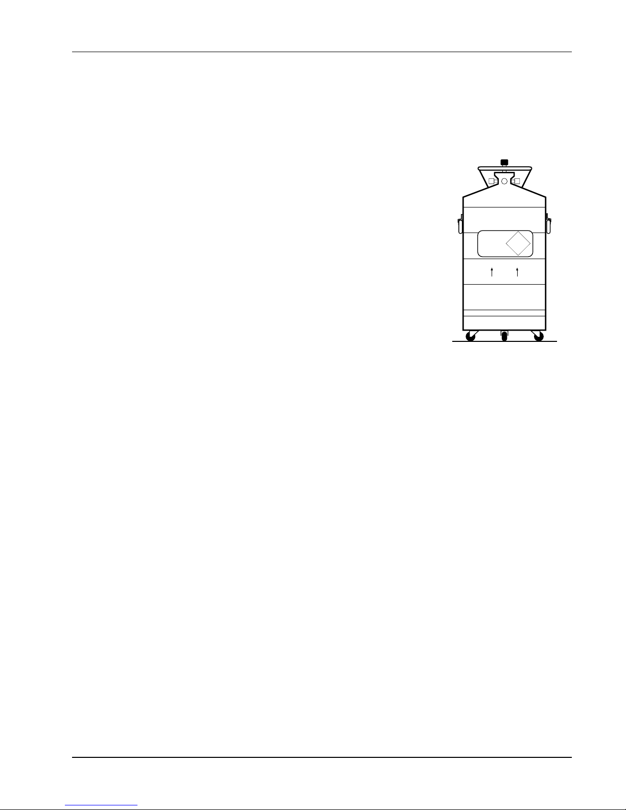
1-3 Cryogenic Storage Dewar ................................................................................................................ 1-7
2-1 Typical Model 330 Rear Panel ......................................................................................................... 2-2
2-2 Heater Jumper (JMP9)..................................................................................................................... 2-9
3-1 Model 330 Front Panel..................................................................................................................... 3-1
3-2 Definition of Front Panel LED Display.............................................................................................. 3-2
3-3 Sensor Calibrations and Precision Options...................................................................................... 3-7
3-4 Record of Zone Settings ................................................................................................................ 3-12
4-1 Typical National Instruments GPIB Configuration from IBCONF.EXE............................................. 4-6
4-2 Optional Serial Interface Connections.............................................................................................. 4-7
5-1 Power Fuse Access ......................................................................................................................... 5-1
5-2 SERIAL I/O RJ-11 Rear Panel Connector Details ........................................................................... 5-2
5-3 SENSOR CHANNEL A and B Rear Panel Connector Details ......................................................... 5-2
5-4 HEATER OUTPUT Rear Panel Connector Details .......................................................................... 5-2
5-5 IEEE-488 Rear Panel Connector Details ......................................................................................... 5-3
5-6 Model 2001 RJ-11 Cable Assembly Wiring Details ......................................................................... 5-4
5-7 Model 2003 RJ-11 to DE-9 Adapter Wiring Details.......................................................................... 5-4
5-8 Model 2002 RJ-11 to DB-25 Adapter Wiring Details........................................................................ 5-4
5-9 Typical Model 330 PCB Layout........................................................................................................ 5-8
6-1 Model 2001 RJ-11 Cable Assembly................................................................................................. 6-4
6-2 Model 2002 RJ-11 to DB-25 Adapter ............................................................................................... 6-4
6-3 Model 2003 RJ-11 to DE-9 Adapter ................................................................................................. 6-4
6-4 Model RM-3H1(-H) Rack-Mount Kit ................................................................................................. 6-5
6-5 Model RM-3H2(-H) Dual Rack-Mount Kit......................................................................................... 6-6
LIST OF TABLES
Table No. Title Page
1-1 Electronic Information for Various Sensors and Temperature Ranges.......................................... 1-3
1-2 Model 330 Specifications................................................................................................................ 1-4
2-1 Sensor Input Setup......................................................................................................................... 2-3
2-2 Diode or Platinum Input Connections ............................................................................................. 2-4
2-3 Sensor Curves (Abbreviated) ......................................................................................................... 2-8
3-1 Sensor Curves (Complete list with write-in area) ........................................................................... 3-4
4-1 Sample BASIC IEEE-488 Interface Program ................................................................................. 4-5
4-2 Serial Interface Parameters............................................................................................................ 4-8
4-3 Sample BASIC Serial Interface Program .......................................................................................4-9
5-1 Sensor Input Setup......................................................................................................................... 5-6
A-1 Standard Diode and Platinum Curves ............................................................................................ A-1
A-2 Thermocouple Curves – Chromel Versus Gold/Iron ......................................................................A-2
A-3 Thermocouple Curves – Chromel Versus Copper .........................................................................A-2
iv Table of Contents

Lake Shore Model 330 Autotuning Temperature Controller User’s Manual
CHAPTER 1
INTRODUCTION
1.0 GENERAL
Lake Shore Cryotronics, Inc. designed and manufactures the Model 330 Autotuning Temperature Controller in
the United States of America. It is a microprocessor-based instrument with digital control of a variable current
output. Features include:
• Four Primary Sensor Configurations (can be ordered in any combination):
– Silicon Diode Model 330-1X
– Platinum Resistor 100 Ω Model 330-2X
– GaAlAs Diode Model 330-3X
– Thermocouple Model 330-4X
• Thermometry:
– Dual Sensor Inputs
– Isolated current sources allow true 4-wire sensor readings.
– Isolated digital and analog power supplies improve sensor readings and quiet heater output
– Nonvolatile Memory Space store up to 21 sensor calibration curves
– SoftCal™ improves system accuracy with simple one to three point calibrations by user
• Five Tuning Modes:
– Autotuning P
– Autotuning PI
– Autotuning PID
– Manual
– Zone (Ten Temperature Zones)
• Control:
– Control Stability to ±2.5 mK
– Three Term PID Control Loop
– 25 or 50 Watt (Maximum), with 2 lower power ranges in decade steps
– Setpoint Ramping
• Interface:
– 4.5-Digit LED Display for High Visibility
– Dual Display of Sensor Temperature in K, °C, or sensor units in volts, ohms
– Setpoint Display
– Continuous Display of Heater Output in 5% increments of the heater range selected
– IEEE-488 and Serial Interface (RS-232C Electrical Format)
We welcome comments concerning this manual. Although we try to keep it free from errors, some may occur.
When reporting specific problems, describe it briefly and include the applicable paragraph, figure, table, and
page number. Send comments to Lake Shore Cryotronics, Attn: Technical Publications, 575 McCorkle Blvd.,
Westerville, Ohio 43082-8888. This manual is subject to change without notice.
Due to our commitment to continuous product improvement, we may modify the Model 330 software with time.
Some changes result from Customer feedback regarding operation on various cryogenic systems. Please
contact us with any observations or suggestions regarding the use of this controller. Also, please return
warranty card to ensure receipt of software updates.
Introduction 1-1
Lake Shore Model 330 Autotuning Temperature Controller User’s Manual
1.1 MODEL 330 TEMPERATURE CONTROLLER DESCRIPTION
The Model 330 is a microcontroller-based Autotuning temperature controller. There are four primary sensor
input types: the Model 330-1X for Silicon Diode Temperature Sensors, the Model 330-2X for Platinum
Resistors, the Model 330-3X for Gallium Aluminum Arsenide Diodes, and the Model 330-4X for
Thermocouples. The Model 330 accommodates these commonly used cryogenic temperature sensors in any
combination (thermocouples optional). They are field selectable, without calibration (except for thermocouples,
which are factory-installed when ordered).
The Model 330 bright red dual LED display shows data from both sensors, or one sensor and the setpoint. It
displays temperature in K, °C, or sensor units in volts (V), millivolts (mV), or ohms (Ω). Heater output current
always displays on a separate bar graph. The full function keypad makes the Model 330 easy to operate.
Precision thermometry is necessary for stable, accurate control, and the Model 330 analog design provides
stable and repeatable measurements. Current source isolation allows for a true four-lead measurement of the
sensor signal. A high-resolution A/D converter digitizes the signal for use in thermometry, control, and
Autotuning. Enhance Model 330 thermometry accuracy with a Lake Shore calibrated sensor and 8000 Series
Precision Calibration Option, or with SoftCal.
Model 330 control software compares the measured control sensor value to the desired control setpoint and
minimizes the difference with a three term (PID) function. Enter control parameters in any one of five tuning
modes: Autotuning P, Autotuning PI, Autotuning PID, Zone, and Manual. Autotuning utilizes information
gathered during setpoint changes to automatically optimize control parameters.
Program up to 10 custom temperature zones so the controller automatically uses pre-programmed PID
settings and heater ranges (computer interface required).
Set the rate at which the ramp setpoint increases or decreases when it is changed. Combine this setting with
the zone feature to ramp through all 10 zones from 2 K to room temperature with only a setpoint change. The
controller changes PID and heater range settings as the setpoint passes through different zones.
Two heater settings provide 25 W or 50 W maximum and accommodate a variety of cryogenic systems. The
Model 330 power output is a quiet, variable DC current for as little noise coupling as possible between the
heater and experiment. If lower power is required, two lower ranges are available with either of the settings.
Both IEEE-488 and Serial Interfaces provide remote access to data from the Model 330 and allows setting of
most front panel functions.
C-330-1-1
Figure 1-1. Model 330 Temperature Controller Front Panel
1-2 Introduction

Lake Shore Model 330 Autotuning Temperature Controller User’s Manual
Table 1-1. Electronic Information for Various Sensors and Temperature Ranges
Suffix 1 2 3 4 *
Sensor Type Silicon Diode 100Ω Platinum RTD GaAlAs Diode Thermocouple
Sensor Temperature
Coefficient Negative Positive Negative Positive
Sensor Units Volts (V) Ohms (Ω) Volts (V) Millivolts (mV)
Input Range 0 – 2.5 V 0 – 300 Ω 0 – 6 V ±15 mV
Sensor Excitation 10 µA ±0.1% 1 mA ±0.01% 10 µA ±0.1% N/A
constant current constant current constant current
The following specifications reflect operational characteristics with the specified Lake Shore Sensor.
Example Lake DT-470-C0 PT-103 TG-120P Ch-AuFe 0.07%
Shore Sensor with 1.4HS calibration with 1.4L calibration with 14J calibration
Sensor Temp. Range 1.4 – 475 K 30 – 800 K 1.4 – 325 K 1.4 – 325 K
Standard Sensor LSCI Curve 10 DIN 43760 Needs Calibration NBS/NIST generated
Curve and 8001
Precision Option
Typical Sensor –30 mV/K at 4.2 K 0.19 Ω /K at 30 K –180 mV/K at 4.2 K 16 µV/K at 4.2 K
Sensitivity –1.9 mV/K at 77 K 0.42 Ω /K at 77 K –1.25 mV/K at 77 K 20 µV/K at 300 K
–2.4 mV/K at 300 K 0.39 Ω /K at 300 K –2.75 mV/K at 300 K
–2.2 mV/K at 475 K 0.33 Ω /K at 800 K
Measurement Resolution:
Sensor Units 0.04 mV 5 m Ω 0.09 mV 0.45 µV
Temperature 1.3 mK at 4.2 K 26 mK at 30 K 0.5 mK at 4.2 K 30 mK at 4.2 K
Equivalence 21 mK at 77 K 12 mK at 77 K 72 mK at 77 K 22 mK at 300 K
16 mK at 300 K 13 mK at 300 K 32 mK at 300 K
18 mK at 475 K 15 mK at 800 K
Sensor Units
Display Resolution 0.1 mV to 1 mV 0.01 Ω to 0.1 Ω 0.1 mV to 1 mV 1 µV
Measurement
Accuracy
Temperature ±50 mK at 4.2 K ±45 mK at 30K ±40 mK at 4.2 K ±406 mK at 4.2K
±125 µV ±0.015% RDG ±12 m Ω ±0.04% RDG ±200 µV ±0.035% ±1.5 µV + 0.1% RDG
†
Accuracy with ±120 mK at 77 K ±62 mK at 77K ±350 mK at 77 K ±110 mK at 300K
Calibrated Sensor and ±80 mK at 300 K ±105 mK at 300K ±150 mK at 300 K
8001 Precision Option ±75 mK at 475 K ±235 mK at 800K
Measurement Temperature Coefficient
Sensor Units ±0.002% ±0.004% ±0.006% ±0.01%
(%RDG/°C Ambient)
Control Stability: ±2.5 mK at 4.2 K ±15 mK at 30 K ±5 mK at 4.2 K ±40 mK at 4.2 K
±25 mK at 77 K ±15 mK at 77 K ±50 mK at 77 K ±40 mK at 300 K
±25 mK at 300 K ±15 mK at 300 K ±50 mK at 300 K
±25 mK at 800 K
* Thermocouple data is for uncompensated inputs.
†
Sensor calibration and 8001 Precision Option are not available for thermocouples. The error listed is for the instrument only.
Table 1-1 identifies the input configurations possible with this instrument. System performance with any of the inputs depends greatly on
sensor characteristics. Much of the typical data presented here is based on the Lake Shore sensor listed in each column. Other sensors
of the same type can be used with the instrument. Similar performance can be expected if the sensor sensitivities match.
Introduction 1-3

Lake Shore Model 330 Autotuning Temperature Controller User’s Manual
Table 1-2. Model 330 Specifications
Thermometry:
Number of Inputs: Two
Sensor Types: Model 330-1X – Silicon Diode
(Sensors Sold Separately) Model 330-2X – Platinum RTD
Model 330-3X – GaAlAs Diode
Model 330-4X – Thermocouple
Accuracy: Based on Model and Sensor Type (Refer to Table 1-1)
Update Rate: Both Channels in 1 second
Precision Curve Storage: Room for twenty 31-point Curves *
Standard Response Curves:
DT-400 Series Silicon Diodes Curve 10
DT-500 Series Silicon Diodes DRC-D or DRC-E1 (Obsolete)
PT-100 Series Platinum RTDs DIN 43760
Thermocouples Ch-AuFe (0.07%), Ch-AuFe (0.03%), Type E (Chromel-Constantan), Type K
(Chromel-Alumel), and Type T (Copper-Constantan)
SoftCal: Entered in Voltage or Temperature *
Control:
Control Type: Digital, three term PID with Autotuning
Automatic Control Mode: P, PI, or PID control, user selectable
Manual Control Mode: Gain (Proportional) 1-999, Reset (Integral) 1-999 sec.,
and Rate (Derivative) 0 - 200% (0-500 sec.)
Control Stability: To ±2.5 mK in a properly designed system for diode
sensors (Refer to Table 1.1)
Setpoint Resolution: 0.01 K or °C below 200, least significant display digit in sensor units
Control Sensor Selection: Front Panel
Ramp Rate: 0.1 to 99.9 K/min
Zones: 10 Zones with Setpoint, P, I, D, and Heater Range *
Heater Output Type: Variable DC Current Source
Heater Setting Resolution: 15 bits
Max. Power To Heater: 50 Watts / 25 Watts (Field Configurable)
Heater Current by Range: High (1 A), Medium (0.3 A), and Low (0.1 A)
Heater Output Compliance: 50 V (50 W) or 25 V (25 W)
Heater Load for Full Power: 50 Ω (50 W) or 25 Ω (25 W)
Minimum Heater Load: 35 Ω (50 W) or 10 Ω (25 W)
Heater Noise: 50 µV + 0.01% of output voltage (with Optional Model 3003 Heater Output
Conditioner, heater noise is lowered by 20 dB)
Front Panel:
Display: Two, 4.5 digit LED
Display Units: Temperature in K or °C. Sensor units in volts (330-1X & -3X),
ohms (330-2X), or millivolts (330-4X)
Setpoint display: Shared with control sensor
Heater output display: 20 digit LED bar graph, percent of full scale current for range
Annunciators: Channel, units, heater range, interface mode
Temperature resolution: 0.01 below 200, 0.1 above
Sensor units resolution: Refer to Table 1-1
Keypad: Numeric plus special function
Computer Interfaces:
IEEE-488 Capabilities: Complies with IEEE-488.2 SH1,AH1,T5,L4,SR1,RL1,PP0,DC1, DT0,C0,E1
Serial Interface: 300 or 1200 baud, RJ-11 connector (RS-232C electrical standard)
General:
Ambient Temperature Range: 20 to 30 °C (68 °F to 86 °F), or with reduced accuracy in range 15 °C to
35 °C (59 °F to 95 °F)
Power Requirements: 110, 120, 220, 240 VAC (+5%-10%), 50 or 60 Hz; 135 Watts
Size: 217 mm x 90 mm x 419 mm (8.5" x 3.5" x 16.5"), half-rack package
Weight: 5 kilograms (11 pounds)
* User-configurable with IEEE-488 or Serial Interface only.)
1-4 Introduction
Channel
Channel
Lake Shore Model 330 Autotuning Temperature Controller User’s Manual
Power Supply
4
Analog Digital
321
5
4-Lead
A
Sensor
Current
Source A
Current
AC Line
Controller
Source B
A/D
Converter
16-Bits
4-Lead
B
Sensor
A/D
Converter
ISO
Program
PROM
ISO
Display
KeypadMicro-
IEEE-488
Interface
RS-232C
Interface
16-Bits
Heater
Output
(25 W or
50 W)
C-330-U-1-2
D/A
Converter
15-Bits
ISO
Isolation (electrical) refers to the separation of voltage
ISO
supplies within the instrument. The 330 design isolates
heater output, measurement, and digital interface circuitry.
Figure 1-2. Model 330 Block Diagram
RAM for
Curves
1.2 CONTROL FUNDAMENTALS AND AUTOTUNE
The Autotuning algorithm determines controller gain (Proportional), reset (Integral), and rate (Derivative) by
observing system time response upon setpoint changes under either P, PI, or PID control.
There are limitations to digital control and Autotuning. First, any control system is inherently unstable if the
sampling rate (frequency) is not greater than twice the system bandwidth (inverse of system time constant).
This is known as the Nyquist criterion. With the current technology used in this controller, i.e., sampling
frequency, etc., digital control is possible for cryogenic systems with time constants near or greater than one
second. Most cryogenic systems operating above 1 kelvin meet this criteria.
Autotuning requires system time response measured as a result of a change in temperature setpoint. Several
points on this response curve must be measured to determine PID parameters. Consequently, for cryogenic
systems where step responses are less than 5 seconds (where there are few measured points), correct
determination of the PID parameters is difficult. Manually select gain and reset (rate is not normally required)
for better temperature control. Fortunately, fast cryogenic systems are not difficult to tune manually.
For slower systems with longer time constants (which can be difficult to tune manually), Autotuning obtains
enough information on a step change to characterize the system and determine proper gain, reset, and rate.
In other conditions, the user may prefer to stay with manual settings. For example, when a closed cycle
refrigerator has very little mass on its second stage and is near its bottom temperature, Autotuning may give
poor results for control settings due to the large temperature fluctuations of the cooling cycle. Adding mass to
the second stage smoothes out these fluctuations, but lengthens cool down time.
Lake Shore simplified the input of the rate time constant to correspond to a percentage of the reset time
constant, i.e., 0 to 200%. Consequently, in manual mode with RATE set to 100%, any change in RESET
causes the controller to automatically calculate the RESET time constant (999/RESET) and set the RATE time
constant at 1/8 of the RESET time constant. This is one-half the conventional Zeigler-Nichols setting for rate
and results in less overshoot of a given setpoint. Therefore, once RATE is set as a percent, you need not
worry about updating its value with setpoint changes resulting in new PI settings. For less RATE, set RATE at
something less than 100%. Remember, many cryogenic systems require no rate (0%).
See the application note titled Fundamentals for Usage of Cryogenic Temperature Controllers in Appendix D if
you are not familiar with cryogenic temperature controllers.
Introduction 1-5

Lake Shore Model 330 Autotuning Temperature Controller User’s Manual
1.3 PRECISION CALIBRATION OPTIONS
The Lake Shore Precision Calibration Option converts calibrated sensor data into breakpoint pairs readable by
the controller program. The Precision Calibration Option is available in three forms: the Model 8000 loads the
breakpoint pairs on a floppy disk in ASCII format for Customer downloading; the Model 8001 is a factoryinstalled NOVRAM; the Model 8002-05 is a field-installed NOVRAM.
Precision Calibration improves specified
accuracy to 0.1K or better over a given calibration range for DT-400 Series Silicon Diode Sensors. Accuracy
for other sensors depends on the type and calibration range.
Lake Shore supplies a copy of break point information containing sensor type, sensor serial number,
maximum allowable error, break point number, voltage (or resistance), temperature, and temperature error,
along with a second sheet containing only the break point temperatures and voltages.
The Precision Calibration Option Table is a piecewise linear interpolation based on the sensor calibration.
Optimum break points are determined by an iterative procedure using weighted linear least squares defined by
either a maximum number of break points allowed or a maximum allowable error. Break point voltages are
derived from the least squares linear equations and differ from the calibration data. Differences between input
table voltages and break point voltage are converted to a corresponding error in temperature by dividing the
voltage difference by the sensitivity. Temperature errors by this method will be considerably less than by linear
interpolation between calibration data points.
1.4 ELECTROSTATIC DISCHARGE
Electrostatic Discharge (ESD) may damage electronic parts, assemblies, and equipment. ESD is a transfer of
electrostatic charge between bodies at different electrostatic potentials caused by direct contact or induced by
an electrostatic field. The low-energy source that most commonly destroys Electrostatic Discharge Sensitive
(ESDS) devices is the human body, which generates and retains static electricity. Simply walking across a
carpet in low humidity may generate up to 35,000 volts of static electricity.
Current technology trends toward greater complexity, increased packaging density, and thinner dielectrics
between active elements, which results in electronic devices with even more ESD sensitivity. Some electronic
parts are more ESDS than others. ESD levels of only a few hundred volts may damage electronic components
such as semiconductors, thick and thin film resistors, and piezoelectric crystals during testing, handling, repair,
or assembly. Discharge voltages below 4000 volts cannot be seen, felt, or heard.
1.4.1 Identification of Electrostatic Discharge Sensitive Components
Below are various industry symbols used to label components as ESDS:
1.4.2 Handling Electrostatic Discharge Sensitive Components
Observe all precautions necessary to prevent damage to ESDS components before attempting installation.
Bring the device and everything that contacts it to ground potential by providing a conductive surface and
discharge paths. As a minimum, observe these precautions:
1. Deenergize or disconnect all power and signal sources and loads used with unit.
2. Place unit on a grounded conductive work surface.
3. Ground technician through a conductive wrist strap (or other device) using 1 MΩ series resistor to protect
operator.
4. Ground any tools, such as soldering equipment, that will contact unit. Contact with operator's hands
provides a sufficient ground for tools that are otherwise electrically isolated.
5. Place ESDS devices and assemblies removed from a unit on a conductive work surface or in a conductive
container. An operator inserting or removing a device or assembly from a container must maintain contact
with a conductive portion of the container. Use only plastic bags approved for storage of ESD material.
6. Do not handle ESDS devices unnecessarily or remove from the packages until actually used or tested.
1-6 Introduction
Lake Shore Model 330 Autotuning Temperature Controller User’s Manual
1.5 HANDLING LIQUID HELIUM AND LIQUID NITROGEN
Liquid Helium (LHe) and liquid nitrogen (LN
and LN
are not explosive, there are certain safety considerations when handling them.
2
) may be used in conjunction with the Model 330. Although LHe
2
1.5.1 Handling Cryogenic Storage Dewars
Operate all cryogenic containers (dewars) in accordance with manufacturer
instructions. Safety instructions are normally posted on the side of each dewar.
Keep cryogenic dewars in a well-ventilated place, protected from the weather, and
away from heat sources. Figure 3-1 shows a typical cryogenic dewar.
NON-
1.5.2 Liquid Helium and Nitrogen Safety Precautions
Transfer LHe and LN
and operate storage dewar controls in accordance with
2
MAGNETIC
LIQUID
HELIUM
FLAMMABLE
manufacturer/supplier instructions. During transfer, follow all safety precautions
written on the storage dewar and recommended by the manufacturer.
KEEP
UPRIGHT
WARNING
• Liquid helium is a potential asphyxiant and can cause rapid suffocation
without warning. Store and use in an adequately ventilated area. DO NOT
vent the container in confined spaces. DO NOT enter confined spaces
where gas may be present unless area is well-ventilated. If inhaled,
remove to fresh air. If not breathing, give artificial respiration. If
breathing is difficult, give oxygen. Get medical attention.
• Liquid helium can cause severe frostbite to exposed body parts. DO
Figure 1-3. Cryogenic
Storage Dewar
NOT touch frosted pipes or valves. For frostbite, consult a physician
immediately. If a physician is unavailable, warm the affected parts with water that is near body
temperature.
NON-
Two essential safety aspects of handling LHe are adequate ventilation and eye and skin protection. Although
helium and nitrogen gases are non-toxic, they are dangerous because they replace air in a normal breathing
atmosphere. Liquid helium is an even greater threat because a small amount of liquid evaporates to create a
large amount of gas. Store and operate cryogenic dewars in open, well-ventilated areas.
When transferring LHe and LN
issuing from it. Protect eyes with full face shield or chemical splash goggles; safety glasses (even with side
shields) are inadequate. Always wear special cryogenic gloves (Tempshield CryoGloves
, protect eyes and skin from accidental contact with liquid or the cold gas
2
®
or equivalent) when
handling anything that is, or may have been, in contact with the liquid or cold gas, or with cold pipes or
equipment. Wear long sleeve shirts and cuffless trousers long enough to prevent liquid from entering shoes.
1.5.3 Recommended First Aid
Post an appropriate Material Safety Data Sheet (MSDS) obtained from the manufacturer/distributor at every
site that stores and uses LHe and LN
. The MSDS specifies symptoms of overexposure and first aid.
2
If a person exhibits symptoms of asphyxia such as headache, drowsiness, dizziness, excitation, excessive
salivation, vomiting, or unconsciousness, remove to fresh air. If breathing is difficult, give oxygen. If breathing
stops, give artificial respiration. Call a physician immediately.
If exposure to cryogenic liquids or cold gases occurs, restore tissue to normal body temperature (98.6 °F) by
bathing it in warm water not exceeding 105 °F (40 °C). DO NOT rub the frozen part, either before or after
rewarming. Protect the injured tissue from further damage and infection and call a physician immediately.
Flush exposed eyes thoroughly with warm water for at least 15 minutes. In case of massive exposure, remove
clothing while showering with warm water. The patient should not drink alcohol or smoke. Keep warm and
rest. Call a physician immediately.
Introduction 1-7
Lake Shore Model 330 Autotuning Temperature Controller User’s Manual
1.6 SAFETY SUMMARY
Observe these general safety precautions during all phases of instrument operation, service, and repair.
Failure to comply with these precautions or with specific warnings elsewhere in this manual violates safety
standards of design, manufacture, and intended instrument use. Lake Shore Cryotronics, Inc. assumes no
liability for Customer failure to comply with these requirements.
The Model 330 protects the operator and surrounding area from electric shock or burn, mechanical hazards,
excessive temperature, and spread of fire from the instrument. Environmental conditions outside of the
conditions below may pose a hazard to the operator and surrounding area.
• Temperature: 5 °C to 40 °C.
• Maximum relative humidity: 80% for temperature up to 31 °C decreasing linearly to 50% at 40 °C.
• Power supply voltage fluctuations not to exceed ±10% of the nominal voltage.
Ground The Instrument
To minimize shock hazard, connect the instrument chassis and cabinet an electrical ground. The instrument
is equipped with a three-conductor AC power cable. Plug the power cable into an approved three-contact
electrical outlet or use a three-contact adapter with the grounding wire (green) firmly connected to an
electrical ground (safety ground) at the power outlet. The power jack and mating plug of the power cable
meet Underwriters Laboratories (UL) and International Electrotechnical Commission (IEC) safety standards.
Do Not Operate In An Explosive Atmosphere
Do not operate the instrument in the presence of flammable gases or fumes. Operation of any electrical
instrument in such an environment constitutes a definite safety hazard.
Keep Away From Live Circuits
Operating personnel must not remove instrument covers. Refer component replacement and internal
adjustments to qualified maintenance personnel. Do not replace components with power cable connected.
To avoid injuries, always disconnect power and discharge circuits before touching them.
Do Not Substitute Parts Or Modify Instrument
Do not install substitute parts or perform any unauthorized modification to the instrument. Return the
instrument to an authorized Lake Shore Cryotronics representative for service and repair to ensure that
safety features are maintained.
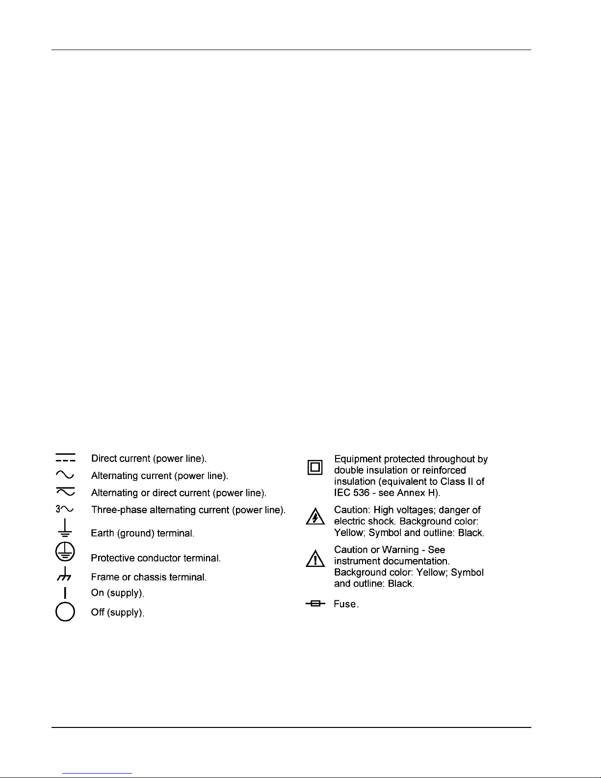
1.7 SAFETY SYMBOLS
1-8 Introduction

Lake Shore Model 330 Autotuning Temperature Controller User’s Manual
CHAPTER 2
INSTALLATION
2.0 GENERAL
This chapter covers general Model 330 installation instructions: Inspection and Unpacking (Paragraph 2.1),
Repackaging for Shipment (Paragraph 2.2), Definition of Rear Panel Connections (Paragraph 2.3), Sensor
Input Settings (Paragraph 2.4), Grounding and Shielding (Paragraph 2.5),. Sensor Installation (Paragraph 2.6),
Sensor Curve Selection (Paragraph 2.7), Precision Calibration Option (Paragraph 2.8), Heater Setup
(Paragraph 2.9), Rack Mounting (Paragraph 2.10), and Power Up (Paragraph 2.11).
2.1 INSPECTION AND UNPACKING
Inspect shipping containers for external damage. Make all claims for damage (apparent or concealed) or
partial loss of shipment in writing to Lake Shore within five (5) days from receipt of goods. If damage or loss is
apparent, please notify the shipping agent immediately.
Open the shipping containers. Use the packing list included with the system to verify receipt of the instrument,
sensor, accessories, and manual. Inspect for damage. Inventory all components supplied before discarding
any shipping materials. If there is freight damage to the instrument, file proper claims promptly with the carrier
and insurance company and notify Lake Shore. Notify Lake Shore immediately of any missing parts. Lake
Shore cannot be responsible for any missing parts unless notified within 60 days of shipment. See the
standard Lake Shore Warranty on the A Page (immediately behind the title page).
2.2 REPACKAGING FOR SHIPMENT
To return the Model 330, sensor, or accessories for repair or replacement, obtain a Return Goods
Authorization (RGA) number from Technical Service in the United States, or from the authorized sales/service
representative from which the product was purchased. Instruments may not be accepted without a RGA
number. When returning an instrument for service, Lake Shore must have the following information before
attempting any repair.
1. Instrument model and serial number.
2. User name, company, address, and phone number.
3. Malfunction symptoms.
4. Description of system.
5. Returned Goods Authorization (RGA) number.
Wrap instrument in a protective bag and use original spacers to protect controls. Repack the system in the
LSCI shipping carton (if available) and seal it with strong paper or nylon tape. Affix shipping labels and
FRAGILE warnings. Write the RGA number on the outside of the shipping container or on the packing slip.
Installation 2-1
Lake Shore Model 330 Autotuning Temperature Controller User’s Manual
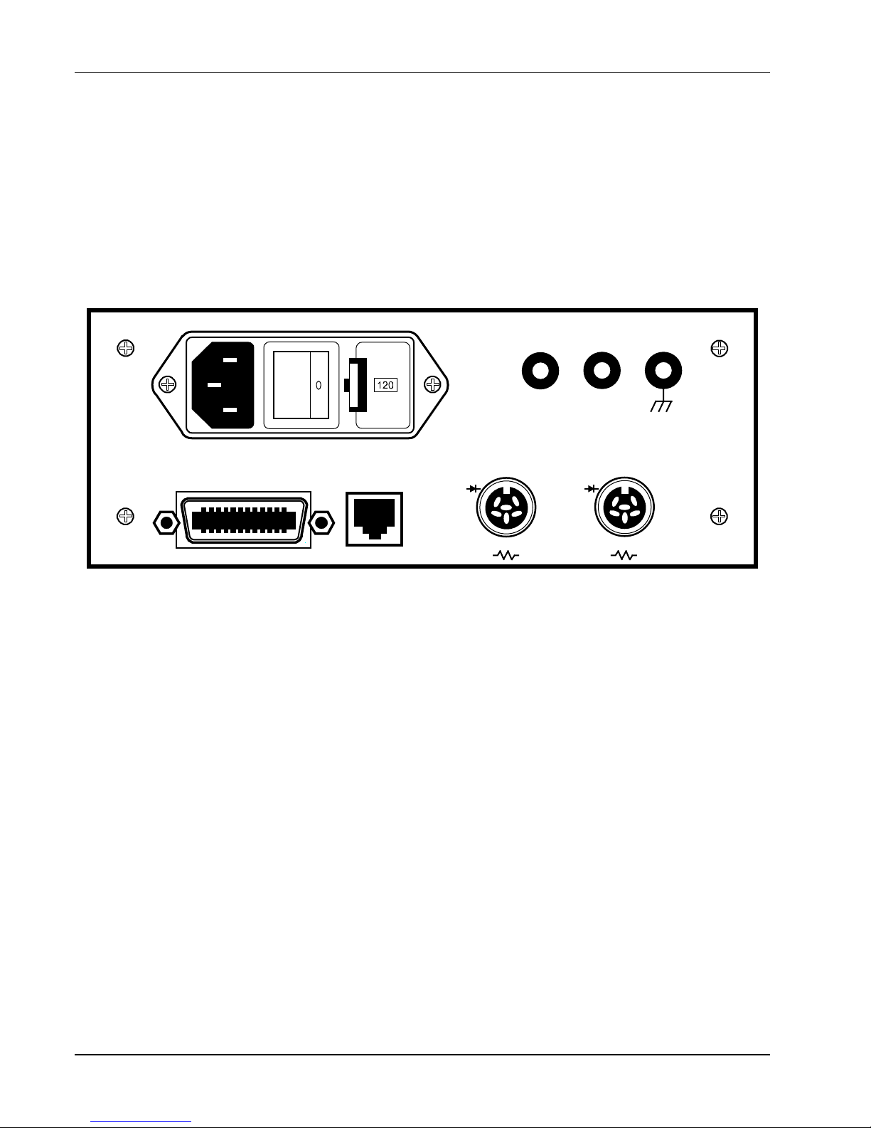
2.3 DEFINITION OF REAR PANEL CONNECTIONS
The Model 330 rear panel consists of the power and fuse assembly, IEEE-488 Interface Connector, Serial I/O
Connector, two Sensor Input connectors, and Heater Output Connections.
CAUTION
• Verify the AC Line Voltage shown in the fuse holder window corresponds to that marked on the rear
panel, and that both settings are appropriate for the intended AC power input. Remove and verify
the proper fuse is installed before inserting the power cord and turning on the instrument.
• Always turn off the instrument before making any rear panel connections. This is especially critical
when making sensor to instrument connections.
HEATER OUTPUT
HI LO GND
IEEE-488 INTERFACE
SH1 AH1 T5 SR1 RL1 PP0 DC1 DT0 C0 E1
C-330-U-2-1
SERIAL I/O
CHANNEL A
I+
V+
I+
I-
V-
CHANNEL B
I+
V+
I+
I-
V-
Figure 2-1. Typical Model 330 Rear Panel
Power and Fuse Assembly. The power and fuse assembly is the entry point for AC power to the unit. The
assembly consists of the power line jack, the power switch, and the fuse holder. The line cord plugs into the
power line jack. The power switch turns the unit on and off. The fuse holder contains a 2 A 3AG Slow Blow
fuse for 90
– 125 VAC or a 1 A 3AG Slow Blow fuse for 210 – 250 VAC. See Paragraph 5.2 for changing power
settings and fuse rating.
IEEE-488 Interface Connector. The standard 24 pin connector connects the controller to any computer
equipped with a IEEE-488 Interface. Refer to Paragraph 4.1 for further information.
Serial I/O Connector. Accepts a standard RJ-11 telephone connector to connect to the user’s computer.
The optional Model 2001 RJ-11 to RJ-11 10-foot Cable, Model 2002 RJ-11 to DB-25 Adapter, and Model 2003
RJ-11 to DE-9 Adapter are available accessories from Lake Shore (refer to Chapter 6 for details). Refer to
Paragraph 4.2 for setup and Serial I/O commands.
Channel A and B Sensor Input Connectors. Connect up to two temperature sensors to the unit. Always turn
off the unit before connecting sensors. Refer to Paragraph 2.6 for details on sensor input setup.
Heater Output Connections. Banana jacks provide HI, LO, and GND heater connections. Refer to
Paragraph 2.10 for details on heater connection setup.
2-2 Installation
Lake Shore Model 330 Autotuning Temperature Controller User’s Manual
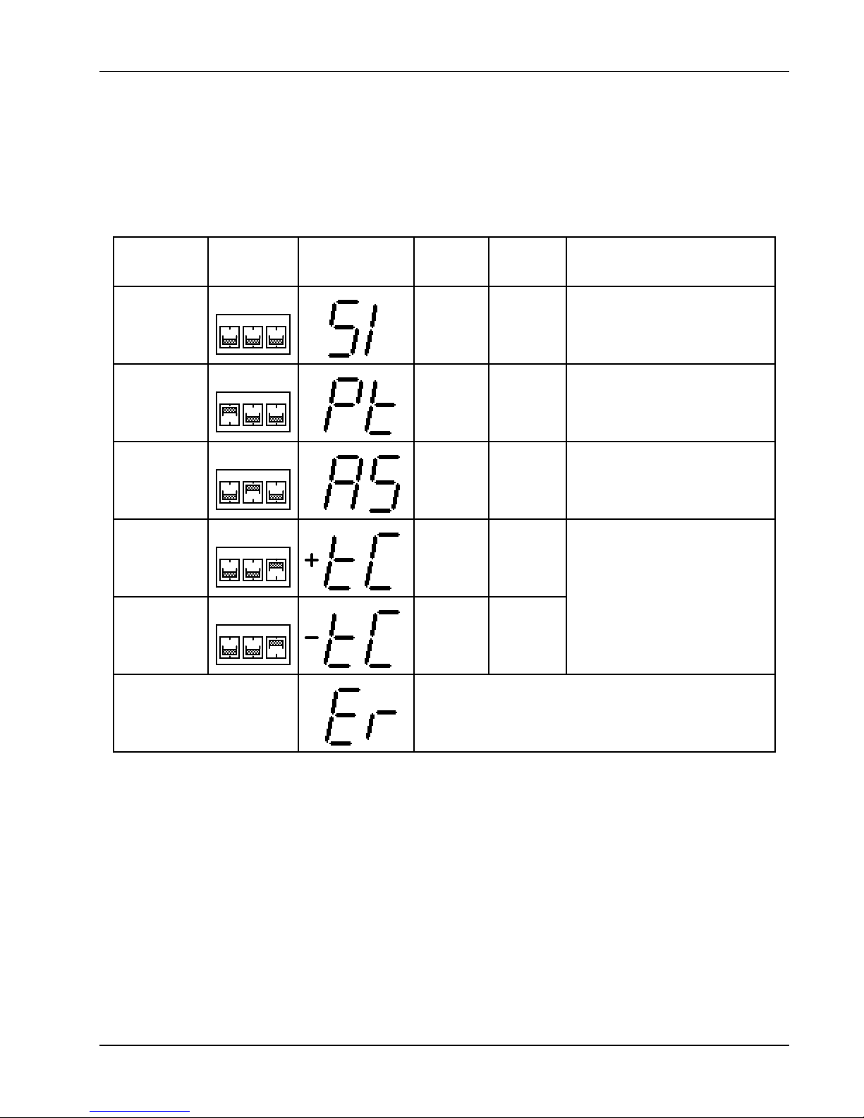
2.4 SENSOR INPUT SETTINGS
To configure sensor input type, set DIP switches S1 and S2 on the main PCB inside the unit. To check DIP
switch settings, press Input Type. Input configurations are shown in Table 2-1.
To change the DIP Switch settings, refer to Paragraph 5.9. Switch diodes and resistor sensors in the field with
no recalibration. Thermocouple sensors cannot be exchanged in the field, but compensation can be turned on
or off with the Input Type key.
Table 2-1. Sensor Input Setup
SensorSensor
Silicon Diode
(DT-400
Series)
Platinum
RTD
GaAlAs
Diode
Thermocouple
(compensation
on)
Thermocouple
(compensation
off)
DIP SwitchDIP Switch
SettingsSettings
PT
AS
12
12
12
12
12
PT
PT
PT
PT
3
AS
3
AS
3
AS
3
AS
3
Display WhenDisplay When
Input TypeInput Type
*
Key is PressedKey is Pressed
TC
TC
TC
TC
TC
SensorSensor
UnitsUnits
Volts 0 to 2.5
InputInput
RangeRange
StandardStandard
Curve(s)Curve(s)
2 Curve10
4 Curve 10 SoftCal
Ohms 0 to 300 3 DIN Curve 43760
Volts 0 to 6.0 None
6 AuFe 0.07% vs. Chromel
Millivolts
10 to 10
7 AuFe 0.03% vs. Chromel
8 Type E (chromel-constantan)
9 Type K (chromel-alumel)
Millivolts
15 to 15
10 Type T (copper-constantan)
If the internal DIP switches are improperly set, the
Improper Switch Setting
display will read Er when the Input TypeInput Type key is
pressed. The normal front panel display will show
dashes - - - - to indicate improper DIP switch setting.
DIP Switch S1 is for Channel A and S2 is for Channel B.
*
2.5 GROUNDING AND SHIELDING
To protect operating personnel, the National Electrical Manufacturer’s Association (NEMA) recommends, and
some local codes require grounded instrument panels and cabinets. This instrument comes with a threeconductor power cable which grounds the instrument when plugged into an appropriate receptacle.
Grounding and shielding signal lines are major setup concerns. The Model 330 allows 4-wire measurement of
diode voltage and resistance. To prevent inaccuracy, isolate diode and resistive sensor leads from earth
ground. However, thermocouple sensors may be grounded. Shield sensor cables whenever possible. Attach
shields to the input connector shield pin. Do not attach the shield at the sensor end.
The heater output is isolated from earth ground. To prevent heater noise coupling into the measurement, do
not allow the heater output to contact earth ground. The rear panel earth ground (GND) is for shielding only.
Model 330 digital logic ties directly to earth ground for interface communications. Separate sensor lines and
digital communication lines whenever possible to prevent excess noise in the measurement.
Installation 2-3

Lake Shore Model 330 Autotuning Temperature Controller User’s Manual
2.6 SENSOR INSTALLATION
This paragraph covers general sensor installation recommendations. See the Lake Shore Product Catalog or
Sensor Guide for installation details and sensor specifications. Call Lake Shore for copies of application notes
or questions concerning sensor installation. General recommendations include:
1. Thermally anchor the sensor.
2. Do not ground the sensor.
3. Shield the leads and connect the shield wire to SHIELD pin only. Do not connect shield at the other end of
the cable.
4. Keep leads as short as possible.
5. Use twisted-pair wire, preferably Lake Shore Duo-Twist™ wire (or equivalent) for two-wire, or
Quad-Twist™ wire (or equivalent) for four-wire applications.
6. Thermally anchor lead wires.
See Paragraph 2.7.1 for installing Diode (Model 330-1X) and Platinum (Model 330-2X) sensors, Paragraph
2.7.2 for Thermocouple (Model 330-4X) sensors, and Paragraph 2.7.3 for sensor input error messages.
2.6.1 Diode (Model 330-1X) and Platinum (Model 330-2X) Connections
Table 2-2. Diode or Platinum Input Connections
The Model 330 has a rear panel 6-pin input connector for silicon
diode (Model 330-1X) or platinum resistance (Model 330-2X)
sensors. Table 2-2 lists lead connections.
See Paragraph 2.7.1.1 for two-lead vs. four-lead measurement,
Paragraph 2.7.1.2 for connecting leads, Paragraph 2.7.1.3 for
sensor mounting, and Paragraph 2.7.1.4 for the effect of
measurement errors due to AC noise.
Terminal Description
1
2
3
4
5
6
– Current
– Voltage
+ Current 1 mA (platinum)
+ Voltage
+ Current 10 µA (diodes)
Shield
2.6.1.1 Two-Lead Versus Four-Lead Measurements
Use a four-lead connection for two lead resistive elements and diodes to avoid current/resistive (IR) drops in
the voltage sensing pair that cause measurement error. In two-lead measurement, the leads that measure
sensor voltage are also current carrying leads. The voltage measured at the instrument is the sum of the
sensor voltage and the IR voltage drop within the two current leads. Because heat flow down the leads can be
critical, small diameter wire and significant resistance per foot is preferred to minimize this heat flow.
Consequently, a voltage drop within the leads may exist.
Two-Lead Measurements
Sometimes system constraints dictate two-lead measurements. Connect
the positive terminals (V+ and I+) together and the negative terminals (V–
and I–) together at the instrument, then run two leads to the sensor.
Expect some loss in accuracy since the voltage measured at the
instrument equals the sum of the sensor voltage and the voltage drop
5
4
Two-Lead
Diode
2
1
across the connecting leads. The exact measurement error depends on
sensor sensitivity and variations resulting from changing temperature. For example, a 10 Ω lead resistance
results in a 0.1 mV voltage error. The resultant temperature error at liquid helium temperature is only 3 mK,
but, because of the diode’s lower sensitivity (dV/dT) at higher temperatures, it becomes 50 mK at liquid
nitrogen temperature.
I+
V+
V–
I–
Four-Lead Measurements
All sensors, both two-lead and four-lead devices, may be
measured in a four-lead configuration to eliminate the
effects of lead resistance. The exact point at which the
connecting leads are soldered to the two-lead sensor
normally results in a negligible temperature uncertainty.
Always use four-lead measurement with Series PT-100 Platinum Sensors attached to the Model 330-2X.
2-4 Installation
5
I+
4
V+
Four-Lead
Diode
2
V–
1
I–
Four-Lead
Platinum
3
I+
4
V+
2
V–
1
I–
A
Lake Shore Model 330 Autotuning Temperature Controller User’s Manual
2.6.1.2 Heat Sinking Sensor Leads
Excessive heat flow through connecting leads to any temperature sensor puts the active sensing element is at
a different temperature than the sample to which the sensor mounts. This yields a temperature offset between
what is measured and the true sample temperature. To eliminate such temperature errors, select and install
connecting leads properly.
To minimize any heat flow through the leads, use leads of small diameter and low thermal conductivity.
Phosphor-bronze or Manganin wire is commonly used in sizes 32 or 36 AWG. Though these wires have fairly
low thermal conductivity, the electrical resistance is not large enough to create problems in measurements.
Thermally anchor lead wires at several temperatures between room temperature and cryogenic temperatures
to guarantee minimal heat conductivity through the leads to the sensor.
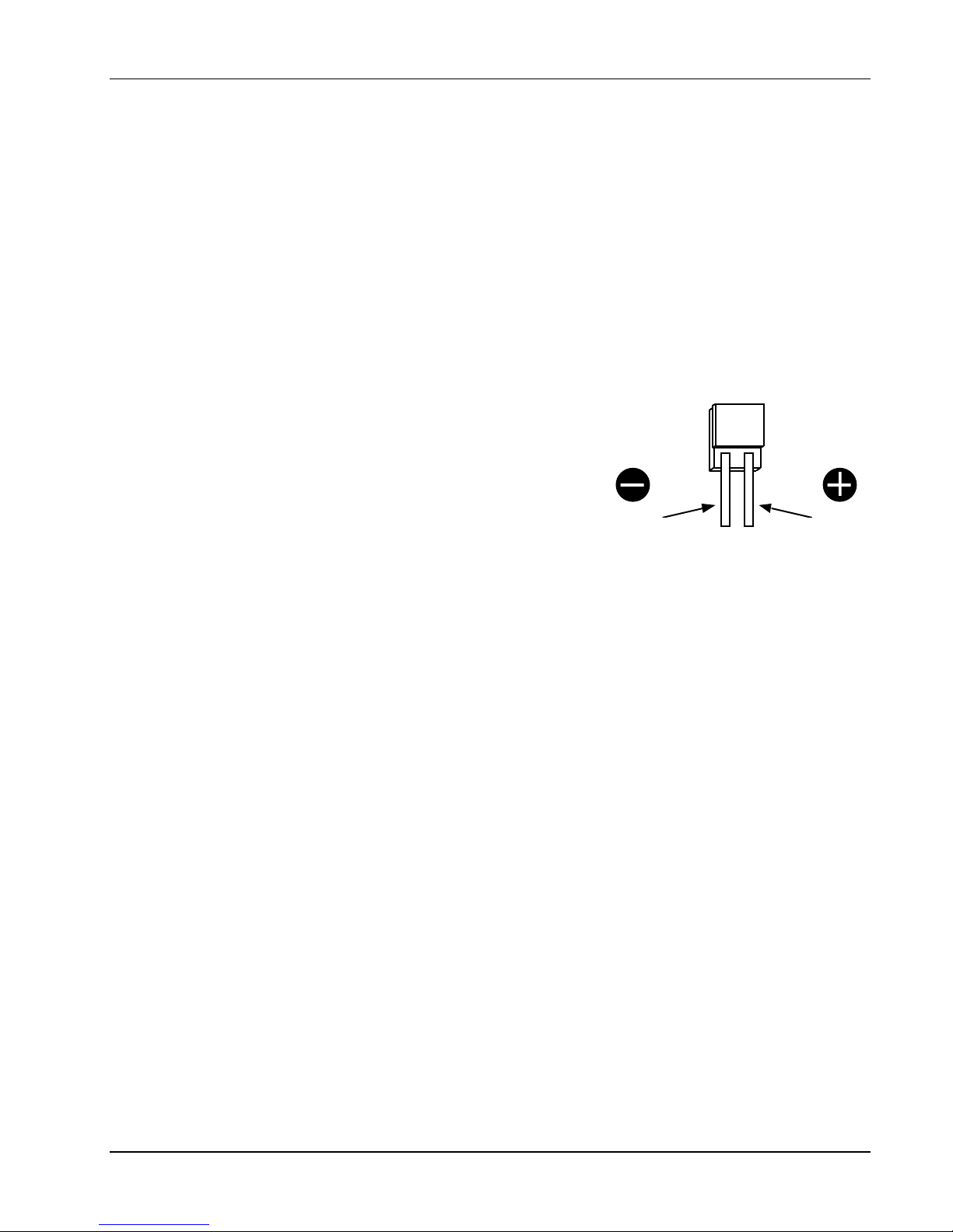
2.6.1.3 Sensor Mounting
Before installing a diode sensor, identify the anode and the cathode.
When viewed with the base down and with the leads towards the
DT-470-SD
Diode Sensor Leads
observer, the positive lead (anode) is on the right and the negative
lead (cathode) is on the left. The figure to the right shows the Lake
Shore DT-470-SD silicon diode sensor lead configuration. For other
sensors, read the accompanying literature or consult the
manufacturer to ensure positive identification of sensor leads. Be
sure the lead identification remains clear even after installation.
Record the sensor serial number and location.
nodeCathode
On the DT-470-SD, the base is the largest flat surface. It is sapphire
with gold metallization over a nickel buffer layer. The base is electrically isolated from the sensing element and
leads; make all thermal contact to the sensor through the base. A thin braze joint around the sides of the SD
package electrically connects to the sensing element. Avoid contact to the sides with any electrically
conductive material.
When installing the sensor, verify there are no electrical shorts or current leakage paths between the leads or
between the leads and ground. IMI-7031 varnish or epoxy may soften varnish-type lead insulation so that high
resistance shunts appear between wires if there was insufficient time for curing. Slide Teflon
®
spaghetti tubing
over bare leads when the possibility of shorting exists. Avoid putting stress on the device leads and allow for
thermal contractions that occur during cooling which may fracture a solder joint or lead installed under tension
at room temperature.
For temporary mounting in cold temperature applications, use a thin layer of Apiezon® N Grease between the
sensor and sample to enhance the thermal contact under slight pressure. The preferred method to mount the
DT-470-SD sensor is the Lake Shore CO Adapter.
CAUTION
• Use a heat sink when soldering sensor lead wires.
• Lake Shore will not warranty replace any device damaged by solder mounting or use of a user-
designed clamp.
NOTE: Apply Stycast® epoxy only to underneath of the DT-470-SD package. Covering the sensor with epoxy
places stress on the sensor that may cause shifts in readings.
For semi-permanent mounting, use Stycast® epoxy instead of Apiezon® N Grease. In all cases, periodically
inspect sensor mounting to verify that good thermal contact to the mounting surface is maintained.
For the Model 330-2X, Series PT-100 Platinum Sensors follow the same procedures for diode type sensors.
The difference is Platinum sensors have no lead polarity and some materials used at cold temperatures will
not tolerate the high temperature range of the Platinum sensor.
Installation 2-5

Lake Shore Model 330 Autotuning Temperature Controller User’s Manual
2.6.1.4 Measurement Errors Due To AC Noise
Poorly shielded leads or improperly grounded measurement systems can introduce AC noise into sensor
leads. For diode sensors, AC noise appears as a shift in the DC voltage measurement due to the non-linear
current/voltage characteristics of the diode. When this occurs, measured DC voltage is too low and the
corresponding temperature indication is high. Measurement error can approach several tenths of a kelvin.
For Series PT-100 Platinum Sensors, the noise causes no DC shift, but it may still degrade accuracy. To
determine if this is a problem in your measurement system, perform either of the two procedures below.
1. Place a capacitor across the diode to shunt the induced AC currents. Capacitor size depends on the noise
frequency. If the noise is related to the power line frequency, use a 10 microfarad capacitor. If AC-coupled
digital noise is suspected (digital circuits or interfaces), then use a capacitor between 0.1 to 1 microfarad.
In either case, if the measured DC voltage increases, there is induced noise in your system.
2. Measure the AC voltage across the diode with an AC voltmeter or oscilloscope. Most voltmeters do not
have the frequency response to measure noise associated with digital circuits or interfaces (which operate
in the MHz range). See the paper “Measurement System-Induced Errors In Diode Thermometry,” J.K.
Krause and B.C. Dodrill, Rev. Sci. Instr. 57 (4), 661, April, 1986 for a thorough discussion of this potential
problem, and the magnitude of error which may result. It is available from Lake Shore.
To greatly reduce the potential for this error, connect twisted leads (pairs) between the controller and the diode
sensors, preferably Duo-Twist™ Cryogenic Wire, which features phosphor bronze wire, 32 or 36 AWG,
twisted at 3.15 twists per centimeter (8 twists per inch). Duo-Twist wire is available from Lake Shore. See the
Lake Shore Product Catalog or contact Lake Shore for details.
2.6.2 Thermocouple (Model 330-4X) Connections
The thermocouple input has a thermal block to connect thermocouple wires. The positive and negative
terminals correspond to V+ and V– and should match the polarity of the thermocouple used. Tighten the screw
terminals carefully; loose connections result in unstable readings and control. For details on thermocouple
operation, see Paragraph 3.5.
2.6.2.1 Thermocouple Compensation
The thermocouple input has a thermal block for connecting thermocouple wires and for temperature
compensation. Thermocouple response curve tables within the instrument are normalized to the ice point of water.
Obtain accurate readings by one of two methods: use an ice bath with a reference junction with the internal room
temperature compensation turned OFF, or, more conveniently, eliminate the reference junction and ice bath, and
use the internal electronic room temperature compensation by turning internal compensation ON.
When a new or different thermocouple is attached to the controller, adjust the offset to compensate for
discrepancies in thermocouple material, leads, and connections. Offset adjustment trimpots are provided
inside the Model 330 to allow offset calibration of the thermocouple. See Paragraph 5.12.
2.6.2.2 Thermocouple Wire Types at Cryogenic Temperatures
Below are recommended thermocouple wire types for cryogenic temperatures. The ANSI color code for
thermocouples is red for the negative lead, while the type of thermocouple determines the positive lead color:
purple (Type E), black (Type J), yellow (Type K), and blue (Type T). For details on thermocouples or other
sensors, see the Lake Shore Temperature Sensor Guide.
Chromel™ vs. Gold with 0.03% or 0.07% Atomic Iron
(0.03% not currently sold by Lake Shore)
Consists of Gold (Au) doped with 0.03 or 0.07 atomic percent Iron (Fe) as the negative thermoelement and
a Ni-Cr alloy (Chromel™) as the positive thermoelement. This thermocouple has relatively high temperature
sensitivity below 25 K, and usable sensitivity below 10 K. It is widely used in cryogenic applications due to its
relatively high thermoelectric sensitivity (>15 µV/K above 10K). Recommended useful temperature range for
the 0.03% Fe is 4 K to 325 K, and for the 0.07% Fe is 1.4 K.
2-6 Installation
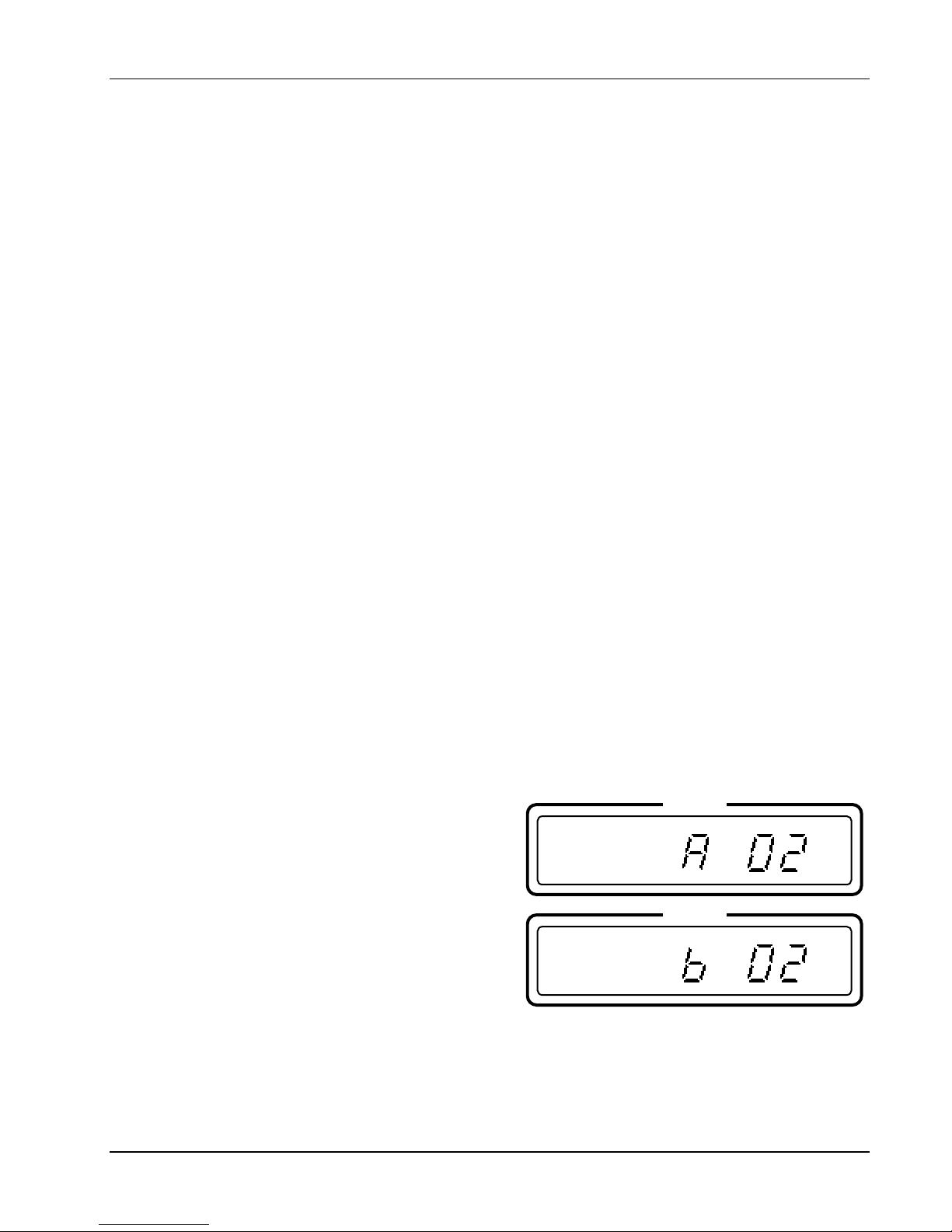
Lake Shore Model 330 Autotuning Temperature Controller User’s Manual
Type E (Chromel™-Constantan)
Type E is a thermocouple pair consisting of a Ni-Cr alloy (Chromel™) as the positive thermoelement and a
Cu-Ni alloy (Constantan) as the negative thermoelement. It has the highest sensitivity of the three standard
thermocouples (E, K and T) typically used for low temperature applications: 8.5 µV/K at 20K. This
thermocouple is best for temperatures down to 40 K. It is recommended for oxidizing or inert environments.
Do not use it in sulfurous or reducing atmospheres, or environments that promote corrosion. Recommended
useful temperature range is 3 K to 475 K.
Type K (Chromel™-Alumel™)
Type K is a thermocouple pair consisting of a Ni-Cr alloy (Chromel™) as the positive thermoelement and a
Cu-Al alloy (Alumel™) as the negative thermoelement. It may be used in inert environments, but not in
sulfurous or reducing atmospheres, or environments that promote corrosion. Sensitivity at 20K: 4.1 µV/K.
Recommended useful temperature range is 3 K to 575 K.
Type T (Copper-Constantan)
Type T is a thermocouple pair consisting of Cu (Copper) as the positive thermoelement and a Cu-Ni alloy
(Constantan) as the negative element. It may be used in a vacuum as well as oxidizing, reducing or inert
environments down to 90 K. At temperatures below 80 K, the thermoelectric properties of the positive
thermoelement depend largely on the impurity of iron. The high thermal conductivity of the copper element
makes this thermocouple the least usable for cryogenic applications. Sensitivity at 20 K: 4.6 µV/K.
Chromel™-CuFe (0.15%)
The Chromel™-Copper/Iron thermocouple consists of a Ni-Cr alloy (Chromel™) as the positive
thermoelement and a Copper/0.15% Iron alloy as the negative thermoelement. Sensitivity at 4.2K: >11 µV/K.
Less expensive than Gold-Chromel™ thermocouples and physically stronger. Recommended useful
temperature range is 4 K to 300 K.
2.6.3 Sensor Input Error Messages
If an input signal from the sensor exceeding full scale is applied to the input leads, an overload condition exists
and is indicated by “OL” on the display.
If no signal or a signal of the wrong polarity exists at the input leads, a Zero Error is indicated by “Er27” for
Channel A or “Er28” for Channel B.
The Model 330 displays dashes “- - - -” if the input switch is improperly set.
2.7 SENSOR CURVE SELECTION
For accurate temperature readings, select the response
Sample
curve that matches the sensor used. To determine curves
currently selected, press Curve. The Sample window
LOC
displays the curve for Sensor A, while the Control window
displays the curve for Sensor B.
This sample display indicates Sensor A is using Curve 02
and Sensor B is also using Curve 02. Curve 02 is the DT-
Control
400 Series Curve 10. The default curve is Curve 02 for
silicon diodes, and Curve 03 for platinum RTDs and
thermocouples.
To change the curve, press and hold the Curve key and
OFF
press the s key to increment the Sensor A curve or the t
key to increment the Sensor B curve number. The curve numbers available are 00 through 31. When the
proper curve number is reached, let go. Table 2-3 lists the standard curves with curve number and
temperature range. If a curve with the wrong temperature coefficient (slope) is selected, the Model 330 selects
the default curve for the sensor type.
Installation 2-7

Lake Shore Model 330 Autotuning Temperature Controller User’s Manual
Table 2-3. Sensor Curves
Sensor curves are defined
as follows:
D and E1 Curve: Older
Lake Shore DT-500 Series
Diode Sensors can still use
the Model 330 when set to
D-Curve (Domestic) or E1Curve (Export).
Curve 10: The Lake Shore
DT-470 Series silicon
diodes follow the same
standard temperature
response Curve 10 which
allows them to interchange
with one another. Lake
Shore programs Curve 10
Curve No. No. of Lines Range (K) Description
00
01
02
03
04
05
06
07
08
09
10
11 – 31
*Values are for thermocouples with compensation. Uncompensated thermocouples can use full ±15 mV range.
31
31
31
31
88
31
31
31
31
31
31
—
1 – 325
1 – 325
1 – 325
14 – 800
2 - 475
—
1.4 – 325 *
4 – 325 *
3 – 425 *
3 – 525 *
3 – 485 *
—
DT-500 DRC Curve D (Domestic)
DT-500 DRC Curve E1 (Export)
DT-400 Series Sensors Curve 10
Platinum DIN 43760
Curve 10 (SoftCal)
Reserved
AuFe 0.07% vs. Chromel
AuFe 0.03% vs. Chromel
Type E
Type K
Type T
User Curves or Precision Calibration
Option (See Table 3-1)
into all Temperature Controllers, Digital Thermometers, and Temperature Transmitters. DT-470 Series silicon
diode sensors come in five bands of tracking accuracy, allowing selection based on both performance and
expense.
Platinum Curve: Users of the Model 330-2X have the option of the standard platinum curve, or the precision
option. The standard platinum curve (see Appendix C) conforms to DIN 43760:1980; IEC 751:1983; and
1904:1984. DIN 43760 is the standard that defines the characteristics of a 100 Ω platinum RTD with a
resistance vs. temperature curve specified by α = 0.00385 Ω/Ω/°C.
Thermocouple Curves: Select the curve that matches the type of thermocouple used.
User Curves 11 thru 31: In addition to the standard curves, Curve Numbers 11 thru 31 provide space for
20 user-defined curves (see Table 2-3). They may be user-defined curves, Precision Calibration Option
Curves purchased from Lake Shore (see Paragraph 2.9), or curves purchased from other vendors. User
defined curves can have up to 97 points plus two end points. Load points into the controller over the serial
interface (Paragraph 4.4), or buy a factory-installed Precision Calibration Option Curve from Lake Shore.
SoftCal Curve. SoftCal curves store in curve location numbers 11 thru 31 as a User Curve. See Table 2-3
and Paragraph 3.2.7 to use SoftCal.
2.8 PRECISION CALIBRATION OPTION
There are three Model 330 precision options. The Model 8000 Precision Calibration Option generates the data
table from a Lake Shore calibrated sensor. The maximum number of data points is 99, but a typical precision
calibration option ranges between 30 and 40 points depending on the sensor type and temperature range of
the calibration. Lake Shore supplies data and accuracy of the fit which the user may enter over the Serial or
IEEE-488 Interface.
Prior to shipment, Lake Shore can also generate a custom sensor response curve from the individual sensor
calibration and store it in the Model 330 via the Model 8001 Precision Calibration Option.
The Model 8001 is
factory-installed when you order an instrument with a calibrated sensor. To order an instrument to be used
with an existing Lake Shore calibrated sensor, supply Lake Shore with the sensor model and serial number at
the time of order.
The Model 8002-05 is for field installations of the Precision Calibration Option in an existing Model 330. Lake
Shore stores the calibration data in a NOVRAM and sends the programmed IC to the customer. The IC is then
installed in the instrument by the customer. The user must supply the Model 330 serial number at the time of
order.
2-8 Installation

Lake Shore Model 330 Autotuning Temperature Controller User’s Manual
2.9 HEATER SETUP
Model 330 heater output is on the rear panel as a Dual Banana Jack. A mating connector is
supplied. Current is driven from the Heater Output HI connection to the LO connection.
Connect a resistive load of 50 Ω for the 50 W att heater setting or 25 Ω for the 25 Watt
heater setting between these two points.
The factory sets the Model 330 jumper per Customer request at the time of order, and
indicates the setting on the B Page inside the front cover. The jumper is set to 25 for 25 W
output or 50 for a 50 W output. To check the heater setting before first operation, see
Paragraph 5.7 for instructions on properly opening and closing the instrument, then look for
JMP9 (Figure 2-2) on the Model 330 Printed Circuit Board (Figure 5-9).
CAUTION: Do not change the Heater Jumper (JMP9) with the instrument power on.
HEATER
25
JMP9
Figure 2-2
Heater Jumper
(JMP9)
50
The heater output is 1 A on High range, 0.3 A
on Medium, and 0.1 A on Low range, and
needs no fuse. The Model 330 powers either a
25 W or 50 W resistive heater for maximum
heater output. Larger resistance may be used,
but results in lower maximum power output.
For example, the output compliance voltage
for a 25 W heater setting is 25 volts, so a 100 Ω heater resistance would allow a maximum power output of
6.25 watts [(25V)
2
/100Ω].
Heater
Range
HIGH
MEDIUM
LOW
Heater
Current
0 to 1 A
0 to 0.3A
0 to 0.1 A
25 W with 25 ΩΩΩΩ
Heater Power
25 Watts
2.5 Watts
0.25 Watts
50 W with 50 ΩΩΩΩ
Heater Power
50 Watts
5 Watts
0.5 Watts
If the heater load drops below 10 Ω for a 25 W heater setting, or 35 Ω for a 50 W heater setting, the output
turns off to prevent instrument overheating. If this occurs, cycle the heater range through OFF to re-engage
the heater.
NOTE: The heater output is isolated from earth ground. To prevent heater noise coupling into the
measurement, do not allow the heater output to contact earth ground. Within a cryostat, use 30 gauge
stranded copper lead wire (ND-30) to connect to the heater. Do not run heater leads coincident with the
sensor leads due to potential capacitive pick-up between the two sets of leads. If heater leads must be close
to sensor leads, twist them so they cross at 90 degrees.
Error 30 (Er30) appears if measured heater output does not match the predicted output, and the controller
turns the heater off. Check heater resistance and test for shorts in heater wiring, then turn the heater on again.
If the error message returns, consult the factory.
2.10 RACK MOUNTING
The Model 330 ships with plastic “feet,” ready for use as a bench instrument. As an option, the Model 330
installs in a standard 19 inch instrument rack. For information on the optional Model 3022 Half-Rack Mounting
Kit for a single controller, see Paragraph 6.3 and Figure 6-4. For information on the optional Model 3026 Dual
Mounting Shelf for side-by-side mounting of two controllers, see Paragraph 6.3 and Figure 6-5.
2.11 POWER UP
This paragraph covers the Power Up Sequence (Paragraph 2.11.1), Power Up (PUP) Configuration
(Paragraph 2.11.2), and Power Up Errors (Paragraph 2.11.3).
2.11.1 Power Up Sequence
1. All elements of the LED display (including Heater %) light.
2. The initials for Lake Shore Cryotronics, Inc. (LSCI) appear in the top window; the numbers 330 appear in
the bottom window.
3. The top line displays the IEEE-488 address (default 12); the bottom line displays the Serial interface Baud
rate (default 300).
4. The Sensor A input type displays in the top window (see Table 2-1), while the curve number displays in
the bottom window (see Table 2-3).
5. The Sensor B input type is displayed in the top window (same as displays in Table 2-1), while the curve
number is displayed in the bottom window (as defined in Table 2-3).
Installation 2-9

Lake Shore Model 330 Autotuning Temperature Controller User’s Manual
2.11.2 Power Up Configuration
The user may store a Model 330 Power Up (PUP) configuration so the Model 330 powers up to a user-defined
state after power down. Retain heater range, setpoint, gain, reset, units, and curve number store in nonvolatile memory even when the line cord is disconnected.
Hold down Enter for 5 seconds to display PUP status in the top window, and either the words On or Off in the
bottom window. To change PUP status, while holding Enter, press the t key to cycle between On and Off.
“On” indicates that power up settings change when instrument settings are changed via the front panel or the
remote interface. “On” is the default PUP condition. If left on, the instrument powers up in the same
configuration it powered down.
“Off” indicates power up memory updates are disabled and the instrument powers up in the same
configuration as when the power up feature was turned off.
2.11.3 Power Up Errors
On power up, the Model 330 checks internal memory. There are two potential error messages. The first error,
“Er01", indicates an unsuccessful attempt to write and read the internal non-volatile RAM. This error is not
user-correctable. Contact the factory.
The second error, “Er02", indicates an unsuccessful attempt to read internal non-volatile RAM for the Model
ID. Sometimes, initializing the Model 330 memory may correct this error. To initialize the memory, hold both
the Escape and Units keys for about 20 seconds. Release once the power up sequence begins. Perform this
operation only under extreme circumstances; it erases all user-defined curves in memory.
2-10 Installation
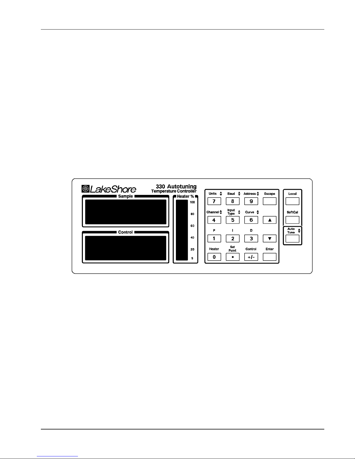
Lake Shore Model 330 Autotuning Temperature Controller User’s Manual
CHAPTER 3
OPERATION
3.0 GENERAL
This chapter covers Definition of Front Panel Controls (Paragraph 3.1), Thermometry Functions (Paragraph
3.2), Control Functions (Paragraph 3.3), Interface and Miscellaneous Functions (Paragraph 3.4), and
Thermocouple Controller Operation (Model 330-04 only, Paragraph 3.5).
3.1 DEFINITION OF FRONT PANEL CONTROLS
The front panel consists of two major sections: 20 front panel keys (Paragraph 3.1.1), and a 2 row by 16
character LCD (Paragraph 3.1.2).
3.1.1 Front Panel Keypad Definitions
Below are abbreviated descriptions of each front panel key. See subsequent paragraphs for more detailed
descriptions of each function.
D-330-U-1-1
Figure 3-1. Model 330 Front Panel
Units: Sets the controller to display temperature units in kelvin (K) or Celsius (C), or sensor units in volts (V),
millivolts (mV), or ohms (Ω), depending on Model number. See Paragraph 3.2.3.
Baud: Selects a Baud Rate of 300 or 1200 for Serial Interface. See Paragraph 3.4.1.
Address: Selects the bus address and terminator for IEEE-488 Interface. See Paragraph 3.4.2.
Channel: Assigns channel sensor to use for Sample and Control. See Paragraph 3.2.2.
Input Type: Only displays the currently selected sensor input type (Paragraph 3.2.1). To change sensor input,
see Paragraph 5.9. This key also controls Display Filter (Paragraph 3.2.4) and Thermocouple Temperature
Compensation (Paragraph 3.2.5).
Curve: Selects the Channel A and B sensor response curve. See Paragraph 3.2.6.
P: Manually adjusts control loop gain (Proportional) term. See Paragraph 3.3.5.1.
I: Manually adjusts control loop reset (Integral) term. See Paragraph 3.3.5.2.
D: Manually adjusts control loop rate (Derivative) term. See Paragraph 3.3.5.3.
Heater: Cycles heater display between LOW, MEDIUM, HIGH, and OFF. See Paragraph 3.3.1.
Operation 3-1
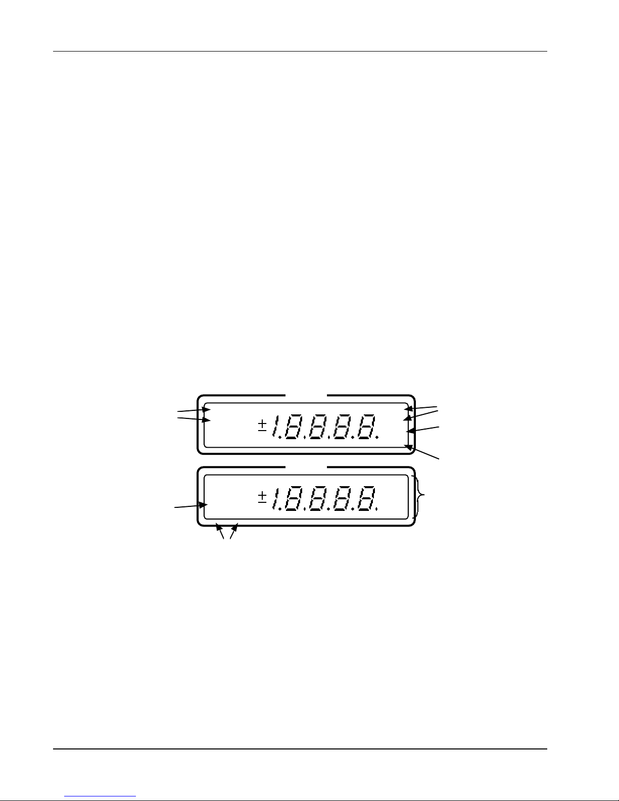
Lake Shore Model 330 Autotuning Temperature Controller User’s Manual
Set Point: Displays or adjusts the control loop temperature setpoint (Paragraph 3.3.2). Press and hold this
key to access the ramp rate feature, where the user sets the rate at which the temperature setpoint
automatically increases or decreases when the user changes the setpoint value. See Paragraph 3.3.3.
Control: Returns bottom display to Control sensor readouts after reading or adjusting the setpoint. See
Paragraph 3.3.2.
Escape: Terminate a function without changing existing settings. To reset most controller parameters to
factory defaults, press and hold both the Escape and Units keys for about 20 seconds. See Paragraph 3.4.4.
s: Used in conjunction with other keys to increment or toggle readings in the upper Sample window.
t: Used in conjunction with other keys to increment or toggle readings in the lower Control window.
Enter: Accepts changes made in the field display. Press and hold the Enter key to access the Power Up
(PUP) configuration setup display. See Paragraph 3.4.5.
Local: Switches controller between Local (LOC) and Remote (REM) operation. See Paragraph 3.4.3.
SoftCal: Improves silicon diode sensor accuracy by setting up a special modification to the Standard Curve
10. See Paragraph 3.2.7.
Autotune: Sets controller tuning to P, PI, PID, Zone, or Off. See Paragraph 3.3.4.
s and t: This symbol next to a key indicates the function operates by holding the key and pressing the s key
to change the top display setting, and the t key to change the bottom display setting.
3.1.2 Front Panel LED Display
In normal operation, the front panel LED display shows Sample/Control temperature readings and heater
status. Other information displays on the various displays to the left and right of the temperature readings. See
Figure 3-2.
Sample
K
Channel
A
B
mV
C
ž
V
Control
K
A
C
B
ž
Setpoint
C-330-U-3-2
SP
mV
V
Units
REM
LOC
TUNE
CAL
HIGH
MED
LOW
OFF
Remote/Local
P, PI, PID, or
Zone Tuning
SoftCal™
Heater Range
Figure 3-2. Definition of Front Panel LED Display
3.2 THERMOMETRY FUNCTIONS
The following front panel keyboard functions relate to Model 330 thermometry:
Input Type (Paragraph 3.2.1),
Channel (Paragraph 3.2.2), Units (Paragraph 3.2.3), Temperature Compensation (Paragraph 3.2.4), Display
Filter (Paragraph 3.2.5), Curve (Paragraph 3.2.6), and SoftCal (Paragraph 3.2.7).
3-2 Operation
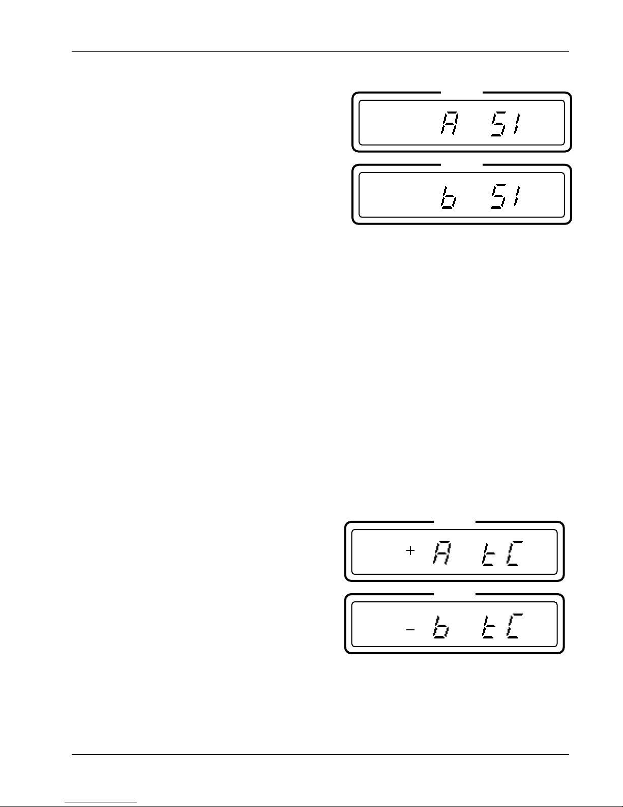
Lake Shore Model 330 Autotuning Temperature Controller User’s Manual
3.2.1 Input Type
Press and hold the Input Type key to verify internal DIP
Sample
switch settings that determine sensor input type as defined
in Table 2-1. When factory-configured, the Model number
corresponds the type of sensor used in each channel of the
controller. The factory configuration appears on the B page
immediately following the title page of this manual. For
example, a Model 330-11 displays:
Control
This display shows that both Channel A and B Sensors are
“SI”, or Silicon Diodes. Other input types are “PT” for
Platinum RTDs, “AS” for GaAlAs Diodes, and “TC” for
Thermocouples. The Input Type display is for information
only; no user changes are available. To change input type,
see Paragraph 5.9.
3.2.2 Channel
The Channel key specifies which sensor to use for Sample and Control. While holding the Channel key,
press the s key to cycle the Sample display between Channel A and B, or the t key to cycle the Control
display between Channel A and B. Release when you reach the desired configuration. Depending on the
installation, either Channel may be used for Sample and Control.
LOC
OFF
3.2.3 Units
The Units key gives slightly different display choices depending on the sensor input and model number. All
four models permit selection of temperature displays in kelvin (K) or Celsius (C). The difference lies in sensor
output selection. For silicon and GaAlAs diodes (Models 330-1X and -3X respectively), the additional units
selection is Volts (V). For the Platinum RTDs (Model 330-2X), the additional units selection is ohms (Ω). For
the thermocouple (Model 330-4X), the additional units selection is millivolts (mV). Units in K is the default for
all models.
NOTE: When the display is set to read in V/Ω/mV, the Autotune, Ramp, and Zone features will not operate.
The user must return the display to K or C before these features will function.
While holding the Units key, press the s key to cycle the Sample sensor units and the t key to cycle the
Control Sensor between K, C, and V/Ω/mV. Sample and Control units need not match.
3.2.4 Thermocouple Temperature Compensation (Model 330-4X Only)
For thermocouple sensors only (Model 330-4X),
Sample
temperature compensation also displays when the
Input Type key is pushed and held (see Paragraph
2.7.2.1.) The display is shown to the right:
LOC
In this display, the Channel A thermocouple has
temperature compensation on, while the Channel B
thermocouple has temperature compensation off. To
Control
change temperature compensation status, while holding
the Input Type key, press the s key to toggle Channel A
temperature compensation on (+) or off (–), or the t key
to toggle the Channel B temperature compensation on (+)
or off (–).
OFF
Operation 3-3
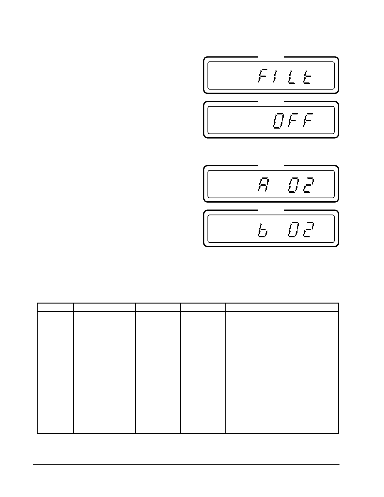
Lake Shore Model 330 Autotuning Temperature Controller User’s Manual
3.2.5 Display Filter
The filter function reads 10 sequential temperature
Sample
readings over 5-seconds and displays a running average. It
quiets the display, making it more readable when the
LOC
sensor is exposed to fluctuating conditions. Filter affects
the display only and does not affect any other control
functions. Filter slows the display; do not use it when
ramping. To turn the filter on, press Enter while holding the
Control
Input Type key. The display to the right appears.
Once the filter display appears, continue to hold the Input
Type key and press the Enter key again to cycle the
display filter on and off. Release when the appropriate
OFF
reading appears.
3.2.6 Curve
For accurate temperature readings, select the response
Sample
curve that matches the sensor. To determine the currently
selected curve, press Curve. The default curve for the
LOC
Model 330-11 is Curve 10 (see Table 3-1). The display tot
the right shows both the Channel A and B Sensor using
Curve 02 - the default setting for a Model 330-11 with two
Silicon Diode Sensors.
Control
Curves 0-10 are standard curves included with the
instrument. Curves 11-31 are user-defined curves or
Precision Option Calibrations. See Table 3-1.
To change the curve, while pressing the Curve key, press
OFF
the s key to increment the Channel A Curve number, or
the t key to increment the Channel B Curve number. Available curve numbers are 00 through 31. Release
when the desired curve number appears, then push the Curve key again. If the selected Curve number
displays, then the Curve has the correct temperature coefficient for the sensor. A different Curve number
indicates an incorrect temperature coefficient for that type sensor. The Curve number changes to the default
curve number for that type sensor.
Table 3-1. Sensor Curves
Curve No. Number of Lines Range (K) Abbreviation Description
00
01
02
03
04
05
06
07
08
09
10
11 - 31
31
31
31
31
88
31
31
31
31
31
31
_____
1 – 325
1 – 325
1 – 325
14 – 800
2 - 475
—
1.4 – 325 †
4 – 325 †
3 – 425 †
3 – 525 †
3 – 485 †
________
D
E1
DT-470
PT DIN
DT-470 *
—
AuFe07%
AuFe03%
E
K
T
_______
DT-500 DRC Curve D
DT-500 DRC Curve E1
DT-400 Series Sensors Curve 10
Platinum DIN Curve 43760
DT-400 Series Sensors Curve 10 *
Reserved
AuFe 0.07% vs. Chromel
AuFe 0.03% vs. Chromel
Type E
Type K
Type T
User-Defined Curves or Precision
Option Calibrations.
* Increased resolution (more data points) version of Curve 10. Used by the Model 330 to generate a SoftCal Curve.
† Values are for thermocouples with compensation. Uncompensated, the thermocouple can use the full ±15 mV range.
3-4 Operation
 Loading...