

Lake Shore 321-01, 321-02, 321-04 User Manual
User’s Manual
Model 321
Temperature Controller
Autotuning
Includes Coverage For:
Model 321-01 – Silicon Diode
Model 321-02 – Platinum Resistor
Model 321-04 – Thermocouple
Lake Shore Cryotronics, Inc.
575 McCorkle Blvd.
Westerville, Ohio 43082-8888 USA
Internet Addresses:
sales@lakeshore.com
service@lakeshore.com
Visit Our Website:
www.lakeshore.com
Fax: (614) 891-1392
Telephone: (614) 891-2243
Methods and apparatus disclosed and described herein have been developed solely on company funds of Lake Shore Cryotronics, Inc.
No government or other contractual support or relationship whatsoever has existed which in any way affects or mitigates proprietary
rights of Lake Shore Cryotronics, Inc. in these developments. Methods and apparatus disclosed herein may be subject to U.S. Patents
existing or applied for. Lake Shore Cryotronics, Inc. reserves the right to add, improve, modify, or withdraw functions, design
modifications, or products at any time without notice. Lake Shore shall not be liable for errors contained herein or for incidental or
consequential damages in connection with furnishing, performance, or use of this material.
Rev. 1.5 P/N 119-004 25 March 2004

Lake Shore Model 321 Autotuning Temperature Controller User’s Manual
1. Lake Shore warrants that this Lake Shore product (the “Product”) will
be free from defects in materials and workmanship for the Warranty
Period specified above (the “Warranty Period”). If Lake Shore receives
notice of any such defects during the Warranty Period and the Product
is shipped freight prepaid, Lake Shore will, at its option, either repair
or replace the Product if it is so defective without charge to the owner
for parts, service labor or associated customary return shipping cost.
Any such replacement for the Product may be either new or equivalent
in performance to new. Replacement or repaired parts will be
warranted for only the unexpired portion of the original warranty or 90
days (whichever is greater).
2. Lake Shore warrants the Product only if it has been sold by an
authorized Lake Shore employee, sales representative, dealer or
original equipment manufacturer (OEM).
3. The Product may contain remanufactured parts equivalent to new in
performance or may have been subject to incidental use.
4. The Warranty Period begins on the date of delivery of the Product or
later on the date of installation of the Product if the Product is installed
by Lake Shore, provided that if you schedule or delay the Lake Shore
installation for more than 30 days after delivery the Warranty Period
begins on the 31st day after delivery.
5. This limited warranty does not apply to defects in the Product resulting
from (a) improper or inadequate maintenance, repair or calibration, (b)
fuses, software and non-rechargeable batteries, (c) software,
interfacing, parts or other supplies not furnished by Lake Shore, (d)
unauthorized modification or misuse, (e) operation outside of the
published specifications or (f) improper site preparation or
maintenance.
6. TO THE EXTENT ALLOWED BY APPLICABLE LAW, THE
ABOVE WARRANTIES ARE EXCLUSIVE AND NO OTHER
WARRANTY OR CONDITION, WHETHER WRITTEN OR ORAL,
IS EXPRESSED OR IMPLIED. LAKE SHORE SPECIFICALLY
DISCLAIMS ANY IMPLIED WARRANTIES OR CONDITIONS OF
MERCHANTABILITY, SATISFACTORY QUALITY AND/OR
FITNESS FOR A PARTICULAR PURPOSE WITH RESPECT TO
THE PRODUCT. Some countries, states or provinces do not allow
limitations on an implied warranty, so the above limitation or
exclusion might not apply to you. This warranty gives you specific
legal rights and you might also have other rights that vary from
country to country, state to state or province to province.
7. TO THE EXTENT ALLOWED BY APPLICABLE LAW, THE
REMEDIES IN THIS WARRANTY STATEMENT ARE YOUR
SOLE AND EXCLUSIVE REMEDIES.
8. EXCEPT TO THE EXTENT PROHIBITED BY APPLICABLE
LAW, IN NO EVENT WILL LAKE SHORE OR ANY OF ITS
SUBSIDIARIES, AFFILIATES OR SUPPLIERS BE LIABLE FOR
DIRECT, SPECIAL, INCIDENTAL, CONSEQUENTIAL OR
OTHER DAMAGES (INCLUDING LOST PROFIT, LOST DATA
OR DOWNTIME COSTS) ARISING OUT OF THE USE,
INABILITY TO USE OR RESULT OF USE OF THE PRODUCT,
WHETHER BASED IN WARRANTY, CONTRACT, TORT OR
OTHER LEGAL THEORY, AND WHETHER OR NOT LAKE
SHORE HAS BEEN ADVISED OF THE POSSIBILITY OF SUCH
DAMAGES. Your use of the Product is entirely at your own risk.
Some countries, states and provinces do not allow the exclusion of
liability for incidental or consequential damages, so the above
limitation may not apply to you.
LIMITED WARRANTY STATEMENT
WARRANTY PERIOD: ONE (1) YEAR
LIMITED WARRANTY STATEMENT (Continued)
9. EXCEPT TO THE EXTENT ALLOWED BY APPLICABLE LAW,
THE TERMS OF THIS LIMITED WARRANTY STATEMENT DO
NOT EXCLUDE, RESTRICT OR MODIFY, AND ARE IN
ADDITION TO, THE MANDATORY STATUTORY RIGHTS
APPLICABLE TO THE SALE OF THE PRODUCT TO YOU.
CERTIFICATION
Lake Shore certifies that this product has been inspected and tested in
accordance with its published specifications and that this product met its
published specifications at the time of shipment. The accuracy and
calibration of this product at the time of shipment are traceable to the
United States National Institute of Standards and Technology (NIST);
formerly known as the National Bureau of Standards (NBS).
FIRMWARE LIMITATIONS
Lake Shore has worked to ensure that the Model 321 firmware is as free
of errors as possible, and that the results you obtain from the instrument
are accurate and reliable. However, as with any computer-based software,
the possibility of errors exists.
In any important research, as when using any laboratory equipment,
results should be carefully examined and rechecked before final
conclusions are drawn. Neither Lake Shore nor anyone else involved in
the creation or production of this firmware can pay for loss of time,
inconvenience, loss of use of the product, or property damage caused by
this product or its failure to work, or any other incidental or consequential
damages. Use of our product implies that you understand the Lake Shore
license agreement and statement of limited warranty.
FIRMWARE LICENSE AGREEMENT
The firmware in this instrument is protected by United States copyright
law and international treaty provisions. To maintain the warranty, the
code contained in the firmware must not be modified. Any changes made
to the code is at the user’s risk. Lake Shore will assume no responsibility
for damage or errors incurred as result of any changes made to the
firmware.
Under the terms of this agreement you may only use the Model 321
firmware as physically installed in the instrument. Archival copies are
strictly forbidden. You may not decompile, disassemble, or reverse
engineer the firmware. If you suspect there are problems with the
firmware, return the instrument to Lake Shore for repair under the terms
of the Limited Warranty specified above. Any unauthorized duplication
or use of the Model 321 firmware in whole or in part, in print, or in any
other storage and retrieval system is forbidden.
TRADEMARK ACKNOWLEDGMENT
Many manufacturers claim designations used to distinguish their products
as trademarks. Where those designations appear in this manual and Lake
Shore was aware of a trademark claim, they appear with initial capital
letters and the ™ or
Apiezon
®
is a trademark of Biddle Instruments.
®
symbol.
CalCurve™, Carbon-Glass™, Cernox™, Duo-Twist™, Quad-Lead™,
Quad-Twist™, Rox™, SoftCal™, and Thermox™ are trademarks of
Lake Shore Cryotronics, Inc.
Chromel™ and Alumel™ are trademarks of Hoskins Manufacturing
Company.
Formvar™ is a trademark of Monsanto Chemical Company.
MS-DOS
®
and Windows® are trademarks of Microsoft Corp.
NI-488.2™ is a trademark of National Instruments.
PC, XT, AT, and PS-2 are trademarks of IBM.
®
Stycast
is a trademark of Emerson & Cuming.
®
Teflon
is a trademark of DuPont De Nemours.
Copyright © 1993–1995, 1997, 1999–2001, and 2004 by Lake Shore Cryotronics, Inc. All rights reserved. No portion of
this manual may be reproduced, stored in a retrieval system, or transmitted, in any form or by any means, electronic,
mechanical, photocopying, recording, or otherwise, without the express written permission of Lake Shore.
A

Lake Shore Model 321 Autotuning Temperature Controller User’s Manual
TABLE OF CONTENTS
Chapter/Paragraph Title Page
1 INTRODUCTION .................................................................................................................................... 1-1
1.0 General ............................................................................................................................... 1-1
1.1 Description .......................................................................................................................... 1-2
1.2 Control Fundamentals and Autotune .................................................................................. 1-5
1.3 Precision Calibration Options.............................................................................................. 1-6
1.4 Safety Summary.................................................................................................................. 1-7
1.5 Safety Symbols ................................................................................................................... 1-7
1.6 Electrostatic Discharge ....................................................................................................... 1-8
1.6.1 Identification of Electrostatic Discharge Sensitive Components ..................................... 1-8
1.6.2 Handling Electrostatic Discharge Sensitive Components ............................................... 1-8
2 INSTALLATION ..................................................................................................................................... 2-1
2.0 General ............................................................................................................................... 2-1
2.1 Inspection and Unpacking................................................................................................... 2-1
2.2 Repackaging For Shipment ................................................................................................ 2-1
2.3 Definition of Rear Panel Connections................................................................................. 2-2
2.4 Environmental Requirements.............................................................................................. 2-3
2.5 Grounding and Shielding .................................................................................................... 2-3
2.6 Sensor Input Settings.......................................................................................................... 2-3
2.7 Sensor Installation............................................................................................................... 2-4
2.7.1 Diode (Model 321-01) and Platinum (Model 321-02) Connections ................................. 2-4
2.7.1.1 Two-Lead Versus Four-Lead Measurements............................................................... 2-4
2.7.1.2 Connecting Leads to the Sensor.................................................................................. 2-5
2.7.1.3 Sensor Mounting .......................................................................................................... 2-5
2.7.1.4 Measurement Errors Due to AC Noise......................................................................... 2-6
2.7.2 Thermocouple (Model 321-04) Connections ................................................................... 2-7
2.7.2.1 Thermocouple Compensation ...................................................................................... 2-7
2.7.2.2 Thermocouple Wire Types at Cryogenic Temperatures .............................................. 2-7
2.7.3 Sensor Input Error Messages .......................................................................................... 2-8
2.8 Sensor Curve Selection ......................................................................................................2-8
2.9 Precision Calibration Option ............................................................................................. 2-10
2.10 Heater Setup ..................................................................................................................... 2-10
2.11 Rack Mounting .................................................................................................................. 2-11
2.12 Power Up .......................................................................................................................... 2-11
2.12.1 Power Up Sequence...................................................................................................... 2-11
2.12.2 Power Up (PUP) Configuration...................................................................................... 2-12
2.12.3 Power Up Errors ............................................................................................................ 2-13
3 OPERATION .......................................................................................................................................... 3-1
3.0 General ............................................................................................................................... 3-1
3.1 Definition of Front Panel Controls ....................................................................................... 3-1
3.1.1 Front Panel Keypad Definitions ....................................................................................... 3-1
3.1.2 Two Row by Sixteen Character LCD ............................................................................... 3-2
3.2 Thermometry Functions ...................................................................................................... 3-3
3.2.1 Input Type ........................................................................................................................ 3-3
3.2.2 Units................................................................................................................................. 3-3
3.2.2.1 Units for Silicon Diode Input (Model 321-01)................................................................ 3-4
3.2.2.2 Units for Platinum Resistor Input (Model 321-02) ........................................................ 3-4
3.2.2.3 Units for Thermocouple Input (Model 321-04).............................................................. 3-4
3.2.3 Thermocouple Temperature Compensation (Model 321-04 Only).................................. 3-5
Table of Contents i

Lake Shore Model 321 Autotuning Temperature Controller User’s Manual
TABLE OF CONTENTS (Continued)
Chapter/Paragraph Title Page
3.2.4 Display Filter.....................................................................................................................3-5
3.2.5 Curve................................................................................................................................3-5
3.2.6 SoftCal™ ..........................................................................................................................3-6
3.2.6.1 SoftCal Errors................................................................................................................3-7
3.2.6.2 Customer-Performed SoftCal........................................................................................3-7
3.2.6.3 Entering Voltage Values from a Lake Shore SoftCal Report........................................3-9
3.2.6.4 Erasing SoftCal Curve ................................................................................................3-10
3.3 Control Functions ..............................................................................................................3-12
3.3.1 Heater High, Low, and Off..............................................................................................3-12
3.3.2 Setpoint ..........................................................................................................................3-13
3.3.2.1 Voltage Resolution (Models 321-01 & -04 Only) ........................................................3-13
3.3.2.2 Resistance Resolution (Model 321-02 Only) ..............................................................3-13
3.3.3 Ramp ..............................................................................................................................3-13
3.3.4 AutoTune........................................................................................................................3-14
3.3.4.1 Initial Values of PID Parameters in Autotuning Mode.................................................3-15
3.3.4.2 Minimum Overshoot....................................................................................................3-15
3.3.4.3 Minimum Time To Setpoint .........................................................................................3-15
3.3.4.4 Gain Only ....................................................................................................................3-15
3.3.5 Manual Control Settings (PID) .......................................................................................3-15
3.3.5.1 Setting Gain (Proportional) .........................................................................................3-15
3.3.5.2 Setting Reset (Integral) ...............................................................................................3-16
3.3.5.3 Setting Rate (Derivative).............................................................................................3-16
3.3.5.4 Effect of Temperature on Tuning Parameters ............................................................3-17
3.3.6 Zone Setting ...................................................................................................................3-17
3.4 Interface and Miscellaneous Functions .............................................................................3-20
3.4.1 Baud ...............................................................................................................................3-20
3.4.2 Analog Out .....................................................................................................................3-20
3.4.3 Factory Default Settings .................................................................................................3-21
3.4.4 Power Up (PUP) Configuration ......................................................................................3-22
3.5 Thermocouple Controller Operation (Model 321-04) ........................................................3-22
3.5.1 Sensor Attachment.........................................................................................................3-22
3.5.2 Thermocouple Curve Selection ......................................................................................3-22
3.5.3 Thermocouple Compensation From Front Panel ...........................................................3-22
3.5.4 Thermocouple Compensation From Remote Interface..................................................3-22
3.5.5 Internal Offset Adjustment..............................................................................................3-23
3.5.6 Curve Format .................................................................................................................3-23
4 REMOTE OPERATION ..........................................................................................................................4-1
4.0 General................................................................................................................................4-1
4.1 Serial Interface Overview ....................................................................................................4-1
4.1.1 Physical Connection.........................................................................................................4-1
4.1.2 Hardware Support ............................................................................................................4-2
4.1.3 Character Format .............................................................................................................4-2
4.1.4 Message Strings...............................................................................................................4-2
4.1.5 Message Flow Control......................................................................................................4-3
4.1.6 Changing Baud Rate........................................................................................................4-3
4.1.7 Serial Interface Basic Programs.......................................................................................4-4
4.1.7.1 Visual Basic Serial Interface Program Setup ................................................................4-4
4.1.7.2 Quick Basic Serial Interface Program Setup ................................................................4-7
4.1.7.3 Program Operation........................................................................................................4-8
4.1.8 Troubleshooting................................................................................................................4-8
ii Table of Contents

Lake Shore Model 321 Autotuning Temperature Controller User’s Manual
TABLE OF CONTENTS (Continued)
Chapter/Paragraph Title Page
4.2 Serial Interface Commands ................................................................................................ 4-9
4.2.1 Display Commands........................................................................................................ 4-10
4.2.2 Control Process Commands.......................................................................................... 4-12
4.2.3 Curve Commands.......................................................................................................... 4-16
4.2.4 Analog Output Commands ............................................................................................ 4-20
4.3 User Curve 11 Loading Program ...................................................................................... 4-21
5 OPTIONS AND ACCESSORIES. .......................................................................................................... 5-1
5.0 General ............................................................................................................................... 5-1
5.1 Models................................................................................................................................. 5-1
5.2 Options................................................................................................................................ 5-1
5.3 Accessories......................................................................................................................... 5-1
6 SERVICE AND CALIBRATION ............................................................................................................. 6-1
6.0 General ............................................................................................................................... 6-1
6.1 General Maintenance.......................................................................................................... 6-1
6.2 Changing Power Setting and Fuse Rating.......................................................................... 6-1
6.3 Rear Panel Connector Definitions....................................................................................... 6-2
6.4 Optional Serial Interface Cable and Adapters .................................................................... 6-4
6.5 Operating Software EPROM Replacement ........................................................................ 6-5
6.6 Error Messages................................................................................................................... 6-6
6.7 Changing Sensor Input Type .............................................................................................. 6-7
6.8 Model 321-01 (Silicon Diode) Calibration ........................................................................... 6-7
6.8.1 Model 321-01 Calibration (With Precision Resistor)........................................................ 6-7
6.8.1.1 Test Equipment ............................................................................................................ 6-7
6.8.1.2 Test Setup .................................................................................................................... 6-7
6.8.1.3 Input Calibration ........................................................................................................... 6-8
6.8.1.4 Analog Output Calibration ............................................................................................ 6-8
6.8.2 Model 321-01 Calibration (Without Precision Resistor)................................................. 6-10
6.8.2.1 Test Equipment .......................................................................................................... 6-10
6.8.2.2 Test Setup .................................................................................................................. 6-10
6.8.2.3 Input Calibration ......................................................................................................... 6-10
6.8.2.4 Analog Output Calibration .......................................................................................... 6-11
6.9 Model 321-02 (Platinum Resistor) Calibration .................................................................. 6-11
6.9.1 Model 321-02 Calibration (With Precision Resistor)...................................................... 6-11
6.9.1.1 Test Equipment .......................................................................................................... 6-11
6.9.1.2 Test Setup .................................................................................................................. 6-11
6.9.1.3 Input Calibration ......................................................................................................... 6-12
6.9.1.4 Analog Output Calibration .......................................................................................... 6-12
6.9.2 Model 321-02 Calibration (Without Precision Resistor)................................................. 6-13
6.9.2.1 Test Equipment .......................................................................................................... 6-13
6.9.2.2 Test Setup .................................................................................................................. 6-13
6.9.2.3 Input Calibration ......................................................................................................... 6-13
6.9.2.4 Analog Output Calibration .......................................................................................... 6-14
6.10 Model 321-04 (Thermocouple) Calibration .......................................................................6-14
6.10.1 Model 321-04 Calibration (With Millivolt Voltage Standard) .......................................... 6-14
6.10.1.1 Test Equipment .......................................................................................................... 6-14
6.10.1.2 Test Setup .................................................................................................................. 6-14
6.10.1.3 Input Calibration ......................................................................................................... 6-15
6.10.1.4 Analog Output Calibration .......................................................................................... 6-15
Table of Contents iii

Lake Shore Model 321 Autotuning Temperature Controller User’s Manual
TABLE OF CONTENTS (Continued)
Chapter/Paragraph Title Page
6.10.1.5 Thermocouple Offset Adjustment ...............................................................................6-15
6.10.1.6 Internal Thermocouple Compensation Adjustment.....................................................6-16
6.10.2 Model 321-02 Calibration (Without Millivolt Voltage Standard)......................................6-16
6.10.2.1 Test Equipment ...........................................................................................................6-16
6.10.2.2 Test Setup...................................................................................................................6-16
6.10.2.3 Input Calibration ..........................................................................................................6-17
6.10.2.4 Analog Output Calibration...........................................................................................6-17
6.10.2.5 Thermocouple Offset Adjustment ...............................................................................6-18
6.10.2.6 Internal Thermocouple Compensation Adjustment.....................................................6-18
APPENDIX A – GLOSSARY OF TERMINOLOGY .....................................................................................A-1
APPENDIX B – HANDLING LIQUID HELIUM AND NITROGEN ...............................................................B-1
B1.0 Introduction ......................................................................................................................... B-1
B2.0 Properties ........................................................................................................................... B-1
B3.0 Handling Cryogenic Storage Dewars ................................................................................. B-1
B4.0 Liquid Helium and Nitrogen Safety Precautions................................................................. B-2
B5.0 Recommended First Aid ..................................................................................................... B-2
APPENDIX C – CURVE TABLES................................................................................................................ C-1
C1.0 General ............................................................................................................................... C-1
APPENDIX D – APPLICATION NOTES...................................................................................................... D-1
D1.0 General ............................................................................................................................... D-1
Fundamentals For Usage Of Cryogenic Temperature Controllers..................................... D-1
Standard Curve 10 – Technical Data ................................................................................. D-8
DT-470 Series Temperature Sensors Installation and Operation .................................... D-10
Measurement System Induced Errors In Diode Thermometry......................................... D-14
iv Table of Contents

Lake Shore Model 321 Autotuning Temperature Controller User’s Manual
LIST OF ILLUSTRATIONS
Figure No. Title Page
1-1 Model 321 Temperature Controller Front Panel ........................................................................... 1-2
1-2 Model 321 Block Diagram............................................................................................................. 1-6
2-1 Typical Model 321 Rear Panel...................................................................................................... 2-2
3-1 Model 321 Front Panel ................................................................................................................. 3-1
3-2 Definition of 2 by 16 Display ......................................................................................................... 3-2
3-3 Sensor Calibrations and Precision Options ................................................................................ 3-11
3-4 Record of Zone Settings ............................................................................................................. 3-19
4-1 Optional Serial Interface Connections .......................................................................................... 4-1
5-1 Model 2001 RJ-11 Cable Assembly .............................................................................................5-3
5-2 Model 2002 RJ-11 to DB-25 Adapter............................................................................................ 5-3
5-3 Model 2003 RJ-11 to DE-9 Adapter.............................................................................................. 5-3
5-4 Model 3022 Rack Mount Kit.......................................................................................................... 5-4
5-5 Model 3026 Dual Rack-Mount Shelf............................................................................................. 5-5
6-1 Power Fuse Access ...................................................................................................................... 6-2
6-2 SERIAL I/O RJ-11 Connector Details........................................................................................... 6-2
6-3 ANALOG OUTPUT Connector Details ......................................................................................... 6-3
6-4 Diode and Platinum SENSOR Connector Details ........................................................................ 6-3
6-5 HEATER Connector Details.......................................................................................................... 6-3
6-6 Model 2001 RJ-11 Cable Assembly Wiring Details ...................................................................... 6-4
6-7 Model 2002 RJ-11 to DB-25 Adapter Wiring Details .................................................................... 6-4
6-8 Model 2003 RJ-11 to DE-9 Adapter Wiring Details ...................................................................... 6-4
6-9 Location of Operating Software EPROMs .................................................................................... 6-5
6-10 Typical Model 321 PCB Layout .................................................................................................... 6-9
B-1 Typical Cryogenic Storage Dewar ................................................................................................B-1
LIST OF TABLES
Table No. Title Page
1-1 Instrument Electronic Information for Various Sensors and Temperature Ranges...................... 1-3
1-2 Model 321 Specifications.............................................................................................................. 1-4
2-1 Diode or Platinum Input Connections ........................................................................................... 2-4
2-2 Sensor Curves .............................................................................................................................. 2-9
3-1 Sensor Curves .............................................................................................................................. 3-6
4-1 Serial Interface Specifications ...................................................................................................... 4-2
4-2 Serial Interface Program Control Properties.................................................................................4-5
4-3 Visual Basic Serial Interface Program .......................................................................................... 4-6
4-4 Quick Basic Serial Interface Program........................................................................................... 4-7
4-5 Serial Interface Command Summary............................................................................................4-9
B-1 Comparison of Liquid Helium to Liquid Nitrogen ..........................................................................B-1
C-1 Standard Diode and Platinum Curves ..........................................................................................C-1
C-2 Thermocouple Curves – Chromel Versus Gold/Iron.....................................................................C-2
C-3 Thermocouple Curves – Chromel Versus Copper........................................................................C-3
Table of Contents v

Lake Shore Model 321 Autotuning Temperature Controller User’s Manual
This Page Intentionally Left Blank
vi Table of Contents

Lake Shore Model 321 Autotuning Temperature Controller User’s Manual
CHAPTER 1
INTRODUCTION
1.0 GENERAL
This chapter provides an introduction to the Model 321 Autotuning Temperature Controller. The
Model 321 was designed and manufactured in the United States of America by Lake Shore Cryotronics,
Inc. The Model 321 Autotuning Temperature Controller is a microprocessor-based instrument with
digital control of a variable current output. The Model 321 features include the following:
• Three Models Available:
– Model 321-01 – Silicon Diode
– Model 321-02 – Platinum Resistor 100 Ω
– Model 321-04 – Thermocouple
• Thermometry:
– Single Sensor Input
– Differential Input Allows Four-Lead Sensor Measurement
– Nonvolatile Memory Space to Store One Precision Calibration Option Curve
– Nonvolatile Memory Space to Store One SoftCal™ Curve
• Five Tuning Modes:
– Autotuning P
– Autotuning PI
– Autotuning PID
– Manual
– Zone (10 Temperature Zones)
• Control:
– Control Stability to ±0.1 K
– Three-Term PID Control Loop
– 25 Watt Heater Power with Two Ranges
– Setpoint Ramping
• Interface:
– Backlit 2 Row by 16 Character LCD for High Visibility
– Display of Sensor Temperature in K, °C, or sensor units in volts, ohms
– Serial Interface (RS-232C Electrical Format)
If you have just received your new Model 321, please proceed to Chapter 2 and become familiar with
the installation instructions. Operation is described in Chapter 3. Remote operation is covered in
Chapter 4. Options and accessories are detailed in Chapter 5. Service and calibration procedures are
provided in Chapter 6. For reference, various appendices are included.
We welcome your comments concerning this manual. Although every effort has been made to keep it
free from errors, some may occur. When reporting a specific problem, please describe it briefly and
include the applicable paragraph, figure, table, and page number. Send comments to Lake Shore
Cryotronics, Attn: Technical Publications, 575 McCorkle Blvd, Westerville, Ohio 43082-8888. The
material in this manual is subject to change without notice.
Due to the Lake Shore commitment to continuous product improvement, it is reasonable to expect that
modifications will be made in the Model 321 software with time. Some of these changes are the result
of Customer feedback regarding operation on various cryogenic systems. We encourage you to contact
us with any observations or suggestions which you have regarding the use of this controller. Also,
please return your warranty card to ensure that any software updates are sent to you.
– Analog Output Corresponding to Temperature
Introduction 1-1
Lake Shore Model 321 Autotuning Temperature Controller User’s Manual
1.1 DESCRIPTION
The Model 321 is a microcontroller-based autotuning temperature controller which provides a simple,
low-cost answer to basic control needs. There are three models: the 321-01 for Silicon Diode
Temperature Sensors, the 321-02 for Platinum Resistors, and the 321-04 for Thermocouples.
The controller displays the temperature in K, °C or sensor units in volts (V), millivolts (mV), or ohms (Ω).
The 2 x 16 LCD simultaneously displays temperature, setpoint, heater range, and heater % current.
Precision thermometry is the most basic building block of any digital controller and is necessary for
stable, accurate control. Careful analog design provides the Model 321 with stable and repeatable
measurements. A differential input allows for a four-lead measurement of the sensor signal. A high
resolution A/D converter digitizes the signal for use in thermometry, control, and autotuning.
The control software in the Model 321 compares the measured value of the control sensor to the
desired control setpoint and acts with three term (PID) function to minimize the difference. Control
parameters can be entered in any one of five tuning modes: Autotuning P, Autotuning PI, Autotuning
PID, Manual, and Zone.
Autotuning represents the Lake Shore commitment to bringing convenience and performance to the
cryogenic measurement and control market. Autotuning utilizes information gathered during setpoint
changes to automatically optimize the control parameters.
The Model 321 allows the user to program up to 10 custom temperature zones where the controller will
automatically use pre-programmed PID settings and heater range.
The ramping feature permits the user to set the rate that the setpoint increases or decreases when the
setpoint is changed. If this feature is combined with the zone feature, the user could do a ramp through
all 10 zones from ≈2 K to room temperature by only changing the setpoint. The controller will change
the PID and heater range settings as the temperature setpoint passes through the different zones.
Two heater ranges, with the high providing 25 watts and the low 2.5 watts, accommodate a variety of
cryogenic cooling systems. The power output of the Model 321 is a quiet, variable DC current to ensure
as little noise coupling as possible between the heater and experiment.
The Serial Interface provides remote access to data from the Model 321 and allows setting of most front
panel functions. The Serial Interface is fully compatible with the older Model 320 (with the exception of
the added heater range), minimizing the need for reprogramming.
Model 321 thermometry accuracy can be enhanced by using a Lake Shore calibrated sensor and 8000
Series Precision Calibration Option, or by the use of SoftCal™.
P-321-1-1.bmp
Figure 1-1. Model 321 Temperature Controller Front Panel
1-2 Introduction

Lake Shore Model 321 Autotuning Temperature Controller User’s Manual
Table 1-1. Electronic Information for Various Sensors and Temperature Ranges
____________________________________________________________________________________________________________________________
Model No. 321-01 321-02 321-04
Sensor Type Silicon diode 100 Ω Platinum RTD Thermocouple
Sensor Temp Coefficient Negative Positive Positive
Sensor Units Volts (V) Ohms (Ω) Millivolts (mV)
Controller Temp. Range 1.4 – 475 K † 14 K – 800 K –273 – 1000 °C †
Input Range 0 – 2.5 V 0 – 300 Ω ±45 mV
*
Sensor Excitation 10 µA ±0.05% 500 µA ±0.01% N/A
constant current constant current
Example Lake Shore Sensor DT-470-C0 PT-103 Ch-AuFe 0.07%
Sensor Temp. Range 1.4 - 475 K 30 - 800 K 1.4 - 325 K
Standard Sensor Curve Curve 10 DIN 43760 NIST generated
The following specifications reflect operational characteristics with the specified Lake Shore Sensor.
Typical Sensor Sensitivity –30 mV/K at 4.2 K 0.19 Ω/K at 30 K 16 µV/K at 4.2 K
–1.9 mV/K at 77 K 0.42 Ω/K at 77 K 20 µV/K at 300 K
–2.4 mV/K at 300 K 0.39 Ω/K at 300 K
–2.2 mV/K at 475 K 0.33 Ω/K at 800 K
Measurement Resolution
Sensor Units 0.04 mV 5 mΩ 1.5 µV
Temperature Equivalence 1.3 mK at 4.2 K 26 mK at 30 K 90 mK at 4.2 K
21 mK at 77 K 12 mK at 77 K 75 mK at 300 K
16 mK at 300 K 13 mK at 300 K
18 mK at 475 K 15 mK at 800 K
Sensor Unit Display Resolution 0.1 mV to 1 mV 0.01 Ω to 0.1 Ω 2 µV
Measurement Accuracy ±0.2 mV ±0.02% RDG ±20 mΩ ±0.05% RDG ±4 µV ±0.05% RDG
Temperature Accuracy ±0.1 K at 4.2 K ±0.2 K at 30 K ±0.8 K at 4.2 K ‡
with Calibrated Sensor ±0.3 K at 77 K ±0.2 K at 77 K ±0.4 K at 300 K
and 8001 Precision Option § ±0.2 K at 300 K ±0.3 K at 300 K
±0.2 K at 475 K ±0.6 K at 800 K
Measurement Temp. Coefficient
Sensor Units (%RDG/°C) ±0.01% ±0.01% ±0.018%
Temperature Equivalence ±8 mK/C° at 4.2 K ±33 mK/°C at 30 K ±200 mK/°C at 4.2 K
±77 mK/°C at 77 K ±22 mK/°C at 77 K ±110 mK/°C at 300 K
±33 mK/°C at 300 K ±64 mK/°C at 300 K
±9 mK/°C at 475 K ±171 mK/°C at 800 K
Setpoint Display Resolution
in Sensor Units 0.1 mV to 1 mV 0.01 Ω to 0.1 Ω 2 µV
_____________________________________________________________________________________________________________________________
*
Thermocouple data are for uncompensated inputs.
†
Dependent on sensor type.
‡
No Model 8001 Precision Calibration Option is available for thermocouples. Error listed is for the controller only.
§
Includes all sensor and controller errors.
Introduction 1-3

Lake Shore Model 321 Autotuning Temperature Controller User’s Manual
_______________________________________________________________________________________________________________________________________ ___________________________________________________________________________________
Table 1-2. Model 321 Specifications
Thermometry:
Number of Inputs: One
Sensor Types: Model 321-01 – Silicon Diode
Model 321-02 – Platinum RTD
Model 321-04 – Thermocouple
Accuracy: Based on Model and Sensor Type (Refer to Table 1-1)
Update Rate: 1 second
Precision Curve Storage: One 97 point curve entered via Serial Interface
SoftCal™: Entered in voltage or temperature
Control:
Control Type: Digital, three term PID with Autotuning
Automatic Control Mode: P, PI, or PID control, user selectable
Manual Control Mode: Gain (Proportional) 1-999, Reset (Integral) 1-999 sec.,
and Rate (Derivative) 0 - 200%
Control Stability: Better than ±0.1 K in a properly designed system for diode and
platinum sensors
Setpoint Resolution: 0.1 K or °C
Heater Output Type: Analog DC Current Source
Heater Setting Resolution: 15 bit
Heater Ranges: 25 W, 2.5 W
Max Power To Heater: 25 W
Max Current To Heater: 1 A
Heater Output Compliance: 25 V
Heater Load: 25 Ω, 25 W required for full power
Heater Noise: 0.005% of full scale power
Ramp Rate: 0.1 to 99.9 K/min
Analog Output:
Default Settings:
Range: 0 to 10 volts at 1 mA max
Default Output: 10 mV/K, 0 – 10 V, 0 – 1000 K
Resolution: 1.22 mV, 0.122 K
Accuracy: ±0.04% of full scale output + measurement accuracy
Programmable Settings:
Range: 0 V = user defined minimum temperature in kelvin
10 V = user defined maximum temperature in kelvin
Minimum temperature resolution is 0.1 K
Front Panel:
Display: 2 row by 16 character LCD
Display Units: Temperature in K or °C. Sensor units in volts (321-01),
ohms (321-02), or millivolts (321-04)
Temperature Resolution: 0.1 K or °C
Sensor Units Resolution: 5 digits
Keypad: Numeric keypad
Interface:
Serial Interface: 300 or 1200 baud, RJ-11 connector (RS-232C electrical standard)
General:
Ambient Temperature Range: 20 to 30 °C (68 °F to 86 °F), or with reduced accuracy in range
15 °C to 35 °C (59 °F to 95 °F)
Power Requirements: 90 – 110, 105 – 125, or 210 – 250 VAC, 50 or 60 Hz; 65 watts
Size: 217 mm wide × 90 mm high × 317 mm deep
(8.5 × 3.5 × 12.5 inches), half-rack package
Weight: 2.7 kilograms (6 pounds)
_______________________________________________________________________________________________________________________________________ ___________________________________________________________________________________
1-4 Introduction

Lake Shore Model 321 Autotuning Temperature Controller User’s Manual
1.2 CONTROL FUNDAMENTALS AND AUTOTUNE
The Model 321 has several features which aid in temperature control of a cryogenic system. These
include standard built-in curves along with the ability to store a single 97 point curve, Serial Interface, a
differential input allowing true four-wire sensor readings, 2 row by 16 character LCD for high visibility,
25 Watt DC current output with short circuit protection of the output, and digital filtering. These and
other features are discussed in detail throughout this manual.
The immediate predecessor of the Model 321 was the Model 320. The Model 320 (along with the Model
330) were the first cryogenic controllers with an Autotuning feature. The Autotuning algorithm
determines the settings of controller gain (Proportional), reset (Integral), and rate (Derivative) by
observing the time response of the system upon changes in setpoint under either P, PI, or PID control.
Since this is a digital system, there are inherent limitations associated with digital control and
Autotuning. First, there is the limitation that any control system is inherently unstable if the sampling
rate (frequency) is not greater than twice the system bandwidth (inverse of system time constant). This
is known as the Nyquist criterion. With the current technology used in this controller, i.e., sampling
frequency, etc., digital control is possible for cryogenic system with time constants near or greater than
one second. Fortunately, most cryogenic systems which operate above 1 kelvin will have time
constants that meet this criteria.
The Autotuning function requires that the system time response be measured as a result of a change in
temperature setpoint. In order to get meaningful data for determining the PID parameters, several
points on this response curve must be measured. Consequently, for cryogenic systems where step
responses are less than ≈5 seconds (where the number of measured points is small), correct
determination of the PID parameters is difficult and better temperature control will normally be achieved
by manual selection of gain and reset (rate will not normally be required). Fortunately, fast cryogenic
systems are not difficult to tune manually.
For slower systems with longer time constants (which can be very difficult to tune manually), Autotuning
can obtain enough information on a step change to characterize the system and determine proper
values of gain, reset, and rate.
There may be other conditions where you will prefer to stay with manual settings. For example, when a
closed cycle refrigerator has very little mass on its second stage and is near its bottom temperature,
attempts at Autotuning may give poor results for control settings due to the large inherent temperature
fluctuations associated with the cooling cycle. Adding mass to the second stage smoothes out these
fluctuations, but lengthens cool-down time.
Lake Shore has simplified the input of the rate time constant in this controller to correspond to a
percentage of the reset time constant, i.e., 0 to 200%. Consequently, if you are in the manual mode and
you set RATE at 100%, on any change in RESET, the controller will automatically calculate the RESET
time constant (999/RESET) and set the RATE time constant at 1/8 of the RESET time constant. This is
one-half the conventional Zeigler-Nichols setting for rate and results in a smaller overshoot of a given
setpoint. Therefore, once RATE is set as a percent, you do not have to worry about updating its value
with setpoint changes resulting in new PI settings. Obviously, if you prefer less RATE, set the rate
setting at something less than 100%. Remember, however, in many cryogenic systems, rate will not be
required anyway, and is consequently set at 0%.
An application note titled Fundamentals for Usage of Cryogenic Temperature Controllers is included
with Appendix D. This application note should be read in detail if you are not familiar with cryogenic
temperature controllers.
Introduction 1-5
Lake Shore Model 321 Autotuning Temperature Controller User’s Manual
1.3 PRECISION CALIBRATION OPTIONS
The Lake Shore Precision Calibration Option allow the user to convert calibrated sensor data into
breakpoint pairs readable by the controller program. The Precision Calibration Option is available in
three forms. The Model 8000 loads the breakpoint pairs on a floppy disk in ASCII format for Customer
downloading. The Model 8001 puts the breakpoint pairs in a NOVRAM that is installed at the factory.
Finally, the Model 80020-05 is a NOVRAM that is installed in the field.
The Precision Calibration Option improves the specified accuracy to 0.1K or better over a given
calibration range for DT-400 Series Silicon Diode Sensors. Accuracy for other sensors depends on the
sensor type and calibration range.
A copy of the break point information containing sensor type, sensor serial number, maximum allowable
error, break point number, voltage (or resistance), temperature and temperature error is supplied. A
second sheet containing only the break point temperatures and voltages is also supplied.
The Precision Calibration Option Table is a piecewise linear interpolation based on the sensor
calibration. Optimum break points are determined by an iterative procedure using weighted linear least
squares defined by either a maximum number of break points allowed or a maximum allowable error.
The break point voltages are the values from the least squares linear equations and will therefore differ
from the calibration data. Differences between voltages from the input table and the break point voltage
are converted to a corresponding error in temperature by dividing the voltage difference by the
sensitivity. Temperature errors by this method will be considerably less than by linear interpolation
between calibration data points.
Power Supply
AC Line
Heater Analog/Digital
12
Current
Display
Source
Sensor
Input
Micro-
Controller
Keypad
(4-Lead)
RS-232C
Differential
Input
A/D
Converter
16 Bits
Program
PROM
Interface
Analog
Output
0-10 V, 1 mA
Heater
Output
25 Watts
D/A
Converter
15 Bits
RAM for
Calibrated
Sensor Curve
Grounds 1 and 2 represent separate isolated power supplies.
C-321-1-2.eps
Ground 1 is connected to Earth.
Figure 1-2. Model 321 Block Diagram
1-6 Introduction
Lake Shore Model 321 Autotuning Temperature Controller User’s Manual
1.4 SAFETY SUMMARY
The following general safety precautions must be observed during all phases of operation, service, and
repair of this instrument. Failure to comply with these precautions or with specific warnings elsewhere in
this manual violates safety standards of design, manufacture, and intended use of the instrument. Lake
Shore Cryotronics, Inc. assumes no liability for Customer failure to comply with these requirements.
The Model 321 protects the operator and surrounding area from electric shock or burn, mechanical
hazards, excessive temperature, and spread of fire from the instrument. Environmental conditions
outside of the conditions below may pose a hazard to the operator and surrounding area.
• Temperature: 5° to 40° C.
• Maximum relative humidity: 80% for temperature up to 31° C decreasing linearly to 50% at 40° C.
• Power supply voltage fluctuations not to exceed ±10% of the nominal voltage.
Ground The Instrument
To minimize shock hazard, the instrument chassis and cabinet must be connected to an electrical
ground. The instrument is equipped with a three-conductor AC power cable. The power cable must
either be plugged into an approved three-contact electrical outlet or used with a three-contact adapter
with the grounding wire (green) firmly connected to an electrical ground (safety ground) at the power
outlet. The power jack and mating plug of the power cable meet Underwriters Laboratories (UL) and
International Electrotechnical Commission (IEC) safety standards.
Do Not Operate In An Explosive Atmosphere
Do not operate the instrument in the presence of flammable gases or fumes. Operation of any electrical
instrument in such an environment constitutes a definite safety hazard.
Keep Away From Live Circuits
Operating personnel must not remove instrument covers. Component replacement and internal
adjustments must be made by qualified maintenance personnel. Do not replace components with power
cable connected. To avoid injuries, always disconnect power and discharge circuits before touching
them.
Do Not Substitute Parts Or Modify Instrument
Because of the danger of introducing additional hazards, do not install substitute parts or perform any
unauthorized modification to the instrument. Return the instrument to an authorized Lake Shore
Cryotronics, Inc. representative for service and repair to ensure that safety features are maintained.
1.5 SAFETY SYMBOLS
Introduction 1-7
Lake Shore Model 321 Autotuning Temperature Controller User’s Manual
1.6 ELECTROSTATIC DISCHARGE
Electrostatic Discharge (ESD) may damage electronic parts, assemblies, and equipment. ESD is a
transfer of electrostatic charge between bodies at different electrostatic potentials caused by direct
contact or induced by an electrostatic field. The low-energy source that most commonly destroys
Electrostatic Discharge Sensitive (ESDS) devices is the human body, which generates and retains
static electricity. Simply walking across a carpet in low humidity may generate up to 35,000 volts of
static electricity.
Current technology trends toward greater complexity, increased packaging density, and thinner
dielectrics between active elements, which results in electronic devices with even more ESD sensitivity.
Some electronic parts are more ESDS than others. ESD levels of only a few hundred volts may
damage electronic components such as semiconductors, thick and thin film resistors, and piezoelectric
crystals during testing, handling, repair, or assembly. Discharge voltages below 4000 volts cannot be
seen, felt, or heard.
1.6.1 Identification of Electrostatic Discharge Sensitive Components
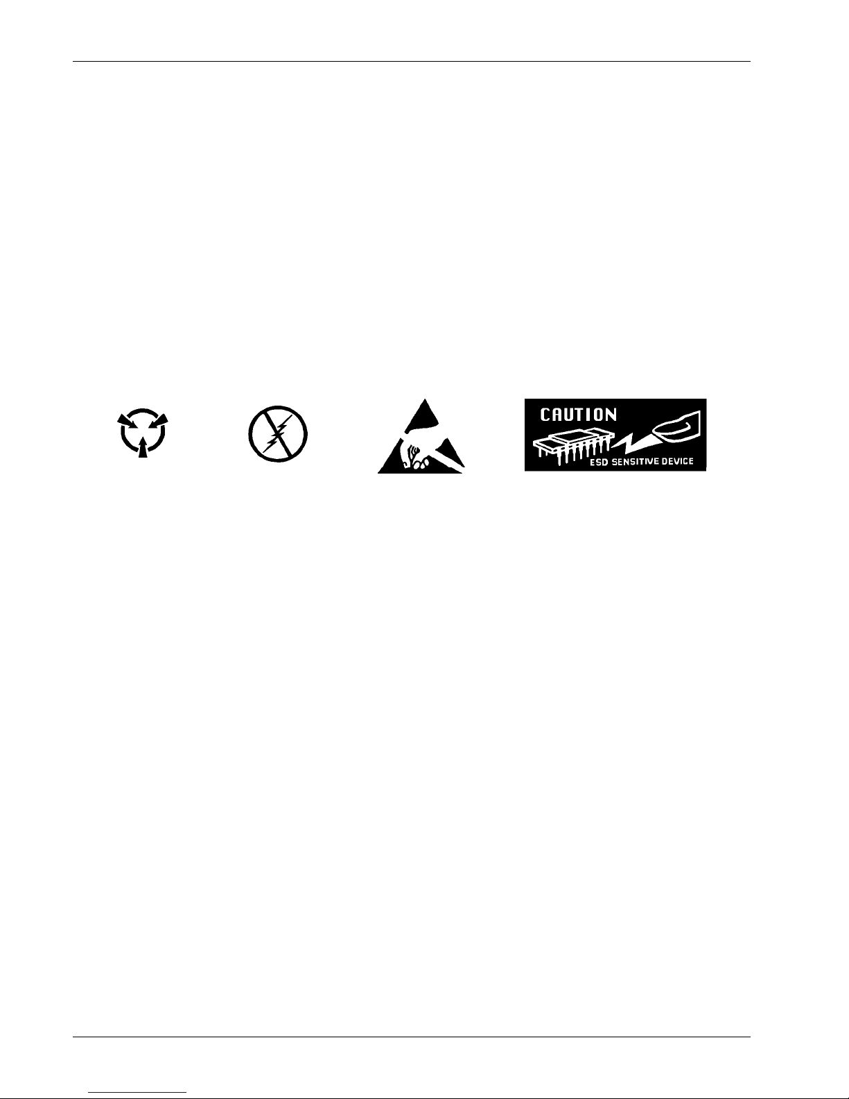
Below are various industry symbols used to label components as ESDS:
1.6.2 Handling Electrostatic Discharge Sensitive Components
Observe all precautions necessary to prevent damage to ESDS components before attempting
installation. Bring the device and everything that contacts it to ground potential by providing a
conductive surface and discharge paths. As a minimum, observe these precautions:
1. Deenergize or disconnect all power and signal sources and loads used with unit.
2. Place unit on a grounded conductive work surface.
3. Ground technician through a conductive wrist strap (or other device) using 1 MΩ series resistor to
protect operator.
4. Ground any tools, such as soldering equipment, that will contact unit. Contact with operator's
hands provides a sufficient ground for tools that are otherwise electrically isolated.
5. Place ESDS devices and assemblies removed from a unit on a conductive work surface or in a
conductive container. An operator inserting or removing a device or assembly from a container
must maintain contact with a conductive portion of the container. Use only plastic bags approved
for storage of ESD material.
6. Do not handle ESDS devices unnecessarily or remove from the packages until actually used or
tested.
1-8 Introduction

Lake Shore Model 321 Autotuning Temperature Controller User’s Manual
CHAPTER 2
INSTALLATION
2.0 GENERAL
This chapter provides general installation instructions for the Model 321 Autotuning Temperature
Controller. Inspection and unpacking instructions are provided in Paragraph 2.1. Repackaging for
shipment instructions are provided in Paragraph 2.2. A definition of rear panel controls is provided in
Paragraph 2.3. Environmental requirements are detailed in Paragraph 2.4. Grounding and shielding
requirements are discussed in Paragraph 2.5. Sensor input settings are detailed in Paragraph 2.6.
Sensor installation recommendations are detailed in Paragraph 2.7. Sensor curve selection is detailed
in Paragraph 2.8. The Precision Calibration Option is discussed in Paragraph 2.9. Heater setup is
detailed in Paragraph 2.10. Rack mounting is discussed in Paragraph 2.11. Finally, the power up
sequence, configuration, and errors are provided in Paragraph 2.12.
2.1 INSPECTION AND UNPACKING
Inspect shipping containers for external damage. All claims for damage (apparent or concealed) or
partial loss of shipment must be made in writing to Lake Shore within five (5) days from receipt of
goods. If damage or loss is apparent, please notify the shipping agent immediately.
Open the shipping containers. A packing list is included with the system to simplify checking that the
instrument, sensor, accessories, and manual were received. Please use the packing list and the spaces
provided to check off each item as the instrument is unpacked. Inspect for damage. Be sure to
inventory all components supplied before discarding any shipping materials. If there is damage to the
instrument in transit, be sure to file proper claims promptly with the carrier and insurance company.
Please inform Lake Shore of such filings. In case of parts or accessory shortages, advise Lake Shore
immediately. Lake Shore cannot be responsible for any missing parts unless notified within 60 days of
shipment. The standard Lake Shore Warranty is included on the A Page (immediately behind the title
page) of this manual.
2.2 REPACKAGING FOR SHIPMENT
If it is necessary to return the Model 321, sensor, or accessories for repair or replacement, a Return
Goods Authorization (RGA) number must be obtained from Technical Service in the United States, or
from the authorized sales/service representative from which the product was purchased. Instruments
may not be accepted without a RGA number. When returning an instrument for service, the following
information must be provided before Lake Shore can attempt any repair.
1. Instrument model and serial number.
2. User name, company, address, and phone number.
3. Malfunction symptoms.
4. Description of system.
5. Returned Goods Authorization (RGA) number.
Wrap instrument in a protective bag and use original spacers to protect controls. Repack the system in
the LSCI shipping carton (if available) and seal it with strong paper or nylon tape. Affix shipping labels
and FRAGILE warnings. Write the RGA number on the outside of the shipping container or on the
packing slip.
Installation 2-1
Lake Shore Model 321 Autotuning Temperature Controller User’s Manual
P-321-2-1.bmp
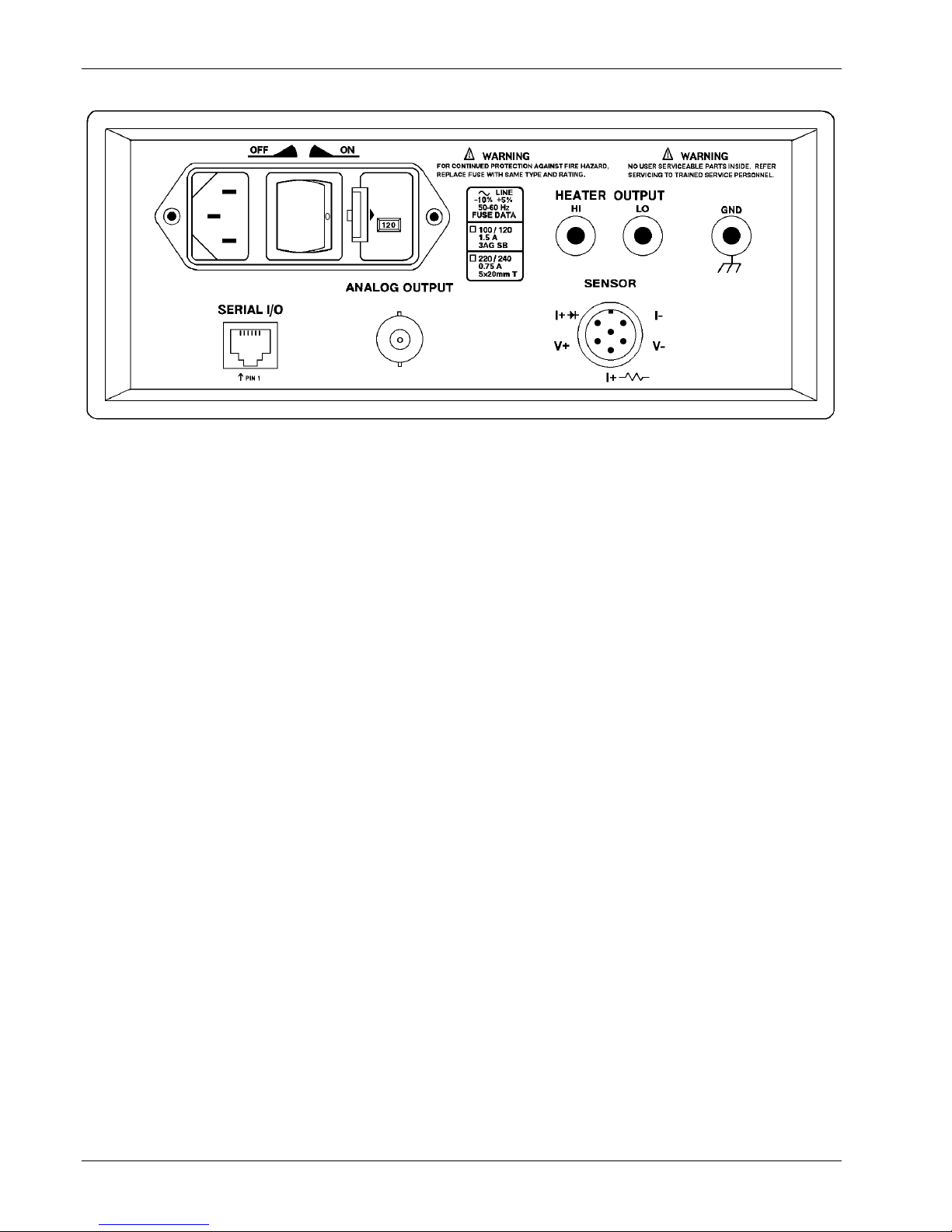
Figure 2-1. Typical Model 321 Rear Panel
2.3 DEFINITION OF REAR PANEL CONNECTIONS
This paragraph provides a description of the Model 321 rear panel connections. The rear panel consists
of the power and fuse assembly, Serial I/O Connector, Analog Output Connector, Sensor Input
Connector, and Heater Output Connector.
CAUTION: Verify that the AC Line Voltage shown in the window on the fuse drawer
corresponds to that marked on the rear panel, and that both these settings are
appropriate for the intended AC power input. Also remove and verify the proper
fuse is installed before inserting the power cord and turning on the instrument.
CAUTION: Always turn off the instrument before making any rear panel connections. This
is especially critical when making sensor to instrument connections.
Power and Fuse Assembly. The power and fuse assembly is the primary entry and control point for
AC power to the unit. The assembly consists of two parts: power line jack and the fuse drawer. The line
cord is connected to the power line jack. Power to the unit is controlled by the power switch located on
the rear panel. Press the right side of the switch for On (l) and the left side for Off (O). The fuse drawer
contains a 1.5 A 3AG Slow Blow fuse for 100
VAC. Refer to Paragraph 6.2 for changing power settings and fuse rating.
– 120 VAC or a 0.75 A 5×20 mm T fuse for 220 – 240
Serial I/O Connector. The Serial I/O (Input/Output) Connector accepts a standard RJ-11 telephone
connector. To connect to the User’s computer, the optional Model 2001 RJ-11 to RJ-11 10-foot Cable,
Model 2002 RJ-11 to DB-25 Adapter, and Model 2003 RJ-11 to DE-9 Adapter are available as
accessories from Lake Shore. Refer to Chapter 4 for Serial Interface setup and commands. Refer to
Chapter 5 for further information on the serial interface connector accessories.
Analog Output BNC Connector. The analog output is available on one Bayonet Nut Connector (BNC).
The signal is on the center conductor while the outer casing is for ground. In the default setting, the
analog output provides a 0
redefine the scaling of this output. Refer to Chapter 3 for further information.
– 10 volt output corresponding to 0 – 1000 K (10 mV/K). The user can also
Sensor Input Connector. A sensor input connector is provided for attaching temperature sensor to
the unit. Always turn off the instrument before connecting the sensor. Refer to Paragraph 2.6 for further
information on setting up the sensor input.
Heater Connectors. Banana jacks provide HI, LO, and GND heater connections (25 Ω, 25 W Heater
recommended). Refer to Paragraph 2.10 for further information on heater connection setup.
2-2 Installation

Lake Shore Model 321 Autotuning Temperature Controller User’s Manual
2.4 ENVIRONMENTAL REQUIREMENTS
The Model 321 is intended for laboratory use. In order to meet and maintain specifications, the
Model 321 should be operated at an ambient temperature range of 20 to 30 °C (68 to 86 °F). The
unit may be operated within the range of 15 to 35 °C (59 to 95 °F) with reduced accuracy.
WARNING: To prevent electrical fire or shock hazards, do not expose this instrument to rain or excess
moisture.
2.5 GROUNDING AND SHIELDING
To protect operating personnel, the National Electrical Manufacturer’s Association (NEMA)
recommends, and some local codes require, instrument panels and cabinets be grounded. This
instrument is equipped with a three-conductor power cable which, when plugged into an appropriate
receptacle, grounds the instrument.
Grounding and shielding of signal lines are major concerns when setting up any precision instrument or
system. The Model 321 allows 4-wire measurement of diode voltage and resistance. To prevent
inaccurate measurements, diode and resistive sensor leads must be isolated from earth ground.
Thermocouple sensors, however, may be grounded. Shield sensor cables whenever possible. Attach
the shields to the shield pin provided in the connector. Do not attach the shield at the sensor end.
The heater output is isolated from earth ground. To prevent heater noise coupling into the
measurement, do not allow the heater output to contact earth ground. Earth ground (GND) is provided
on the rear panel for shielding purposes only.
Digital logic in the Model 321 is tied directly to earth ground for interface communications. The sensor
lines and digital communication lines should be separated whenever possible to prevent excess noise
in the measurement.
2.6 SENSOR INPUT SETTINGS
The sensor input type is established at the factory before shipping. Sensor input type is configured by
setting DIP switches S1 and S2 on the main PCB inside the unit. If you wish to check the DIP switch
settings, the configurations are as follows.
Platinum
*
Thermocouple
(Model 321-04)
DIP Switch S1
Silicon Diode
(Model 321-01)
S1-1 Closed Open Open
S1-2 Open Closed Open
S1-3 Open Open Closed
S1-4 Open Open Closed
(Model 321-02)
*
To change sensor input type, DIP switches on S1 and S2 must be switched identically.
DIP Switch S2
Silicon Diode
(Model 321-01)
S2-1 Closed Open Open
S2-2 Open Closed Open
S2-3 Open Open Closed
S2-4 Open Open Closed
Platinum
(Model 321-02)
*
Thermocouple
(Model 321-04)
To change the DIP Switch settings, refer to Paragraph 6.7. The Model 321 must be recalibrated when
switched between sensor input types.
Diode and Platinum connections are defined in Paragraph 2.7.1. Thermocouple connections are
described in Paragraph 2.7.2. Finally, thermocouple compensation is discussed in Paragraph 2.7.2.1.
Installation 2-3
Lake Shore Model 321 Autotuning Temperature Controller User’s Manual
2.7 SENSOR INSTALLATION
Abbreviated sensor installation recommendations for the Model 321 are included in this paragraph.
Please refer to the Lake Shore Product Catalog or Sensor Guide for installation details and sensor
specifications. Call Lake Shore for copies of application notes or with questions or comments
concerning sensor installation. The following are general recommendations on sensor installation:
1. Do not ground the sensor.
2. Shield the leads and connect the shield wire to SHIELD on the screw terminal connector only.
Do not connect shield at the other end of the cable.
3. Keep leads as short as possible.
4. Use twisted-pair wire. Use of Lake Shore Duo-Twist™ wire (or equivalent) for two-wire, or QuadTwist™ wire (or equivalent) for four-wire applications, is strongly recommended.
5. Lead wires should be thermally anchored.
Sensor installation is provided in two parts. Diode (Model 321-01) and Platinum (Model 321-02) sensor
connections are detailed in Paragraph 2.7.1. Thermocouple (Model 321-04) sensor connections are
detailed in Paragraph 2.7.2. Finally, sensor input error messages are described in Paragraph 2.7.3.
2.7.1 Diode (Model 321-01) and Platinum (Model 321-02) Connections
The Model 321 has a rear panel 6-pin input connector for silicon diode (Model 321-01) or platinum
resistance (Model 321-02) sensors. The lead connections are defined in Table 2-1.
Table 2-1. Diode or Platinum Input Connections
Terminal Description
1
2
3
4
5
6
– Current
– Voltage
+ Current 500 µA (platinum)
+ Voltage
+ Current 10 µA (diodes)
Shield
Paragraph 2.7.1.1 discusses two-lead versus four-lead measurements. Paragraph 2.7.1.2 discusses
connecting leads. Sensor mounting is covered in Paragraph 2.7.1.3. Finally, Paragraph 2.7.1.4
describes the effect of measurement errors due to AC noise.
2.7.1.1 Two-Lead Versus Four-Lead Measurements
The use of a four-lead connection is highly recommended for two lead resistive elements and
diodes to avoid introducing current/resistive (IR) drops in the voltage sensing pair which translates
into a temperature measurement error. In the two lead measurement scheme, the leads used to
measure the sensor voltage are also the current carrying leads. The resultant voltage measured at
the instrument is the sum of the temperature sensor voltage and the IR voltage drop within the two
current leads. Since in a cryogenic environment, the flow of heat down the leads can be of critical
concern, normally wire of small diameter and significant resistance per foot is preferred to minimize
this heat flow. Consequently, a voltage drop within the leads can be present.
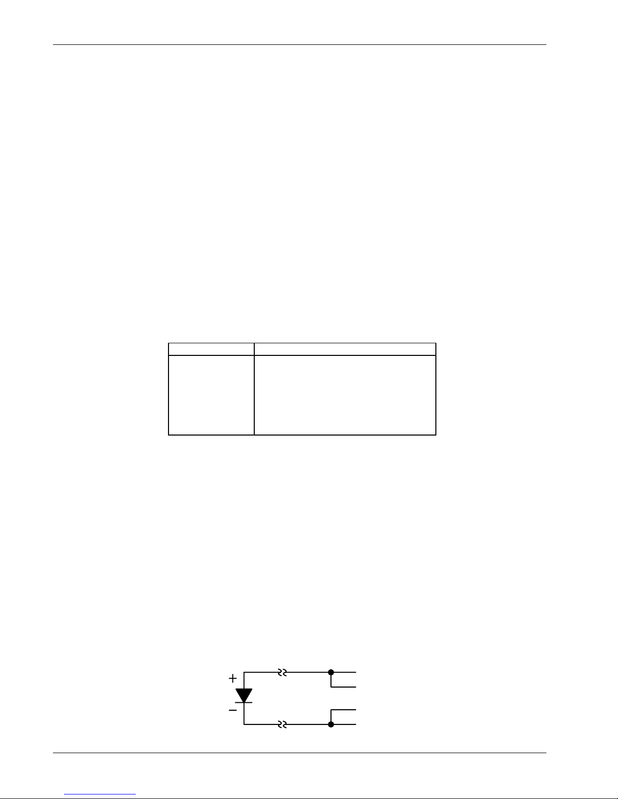
1. Two-Lead Measurements
Sometimes system constraints dictate the use of two-lead measurements. Connect the positive
terminals (V+ and I+) together and the negative terminals (V– and I–) together at the
instrument, then run two leads to the sensor.
I+
Two-Lead
Measurements
V+
V
I
2-4 Installation
Lake Shore Model 321 Autotuning Temperature Controller User’s Manual
Some loss in accuracy can be expected since the voltage measured at the voltmeter becomes
the sum of the sensor voltage and the voltage drop across the connecting leads. The exact
measurement error will depend on sensor sensitivity and variations resulting from changing
temperature. For example, a 10 Ω lead resistance will result in a 0.1 mV voltage error. The
resultant temperature error at liquid helium temperature is only 3 mK, but, because of the
diode’s lower sensitivity (dV/dT) at higher temperatures, it becomes 10 mK at liquid nitrogen
temperature.
2. Four-Lead Measurements
All sensors, including both two-lead and four-lead devices, can be measured in a four-lead
configuration to eliminate the effects of lead resistance. The exact point at which the connecting
leads are soldered to the two-lead sensor normally results in a negligible temperature
uncertainty.
Four-Lead
Diode
The four-lead measurement configuration should always be used with Series PT-100 Platinum
Sensors being attached to the Model 321-02.
2.7.1.2 Connecting Leads To The Sensor
An excessive heat flow through the connecting leads to any temperature sensor can create a
situation where the active sensing element is at a different temperature than the sample to which
the sensor is mounted. This is then reflected as a real temperature offset between what is
measured and the true sample temperature. Such temperature errors can be eliminated by proper
selection and installation of the connecting leads.
In order to minimize any heat flow through the leads, the leads should be of small diameter and low
thermal conductivity. Phosphor-bronze or Manganin wire is commonly used in sizes 32 or 36 AWG.
These wires have a fairly low thermal conductivity yet the electrical resistivities are not so large as
to create any problems in measurements.
Lead wires should also be thermally anchored at several temperatures between room temperature
and cryogenic temperatures to guarantee that heat is not being conducted through the leads to the
sensor.
V+
V–
I+
Four-Lead
Platinum
I–
V+
V–
I+
I–
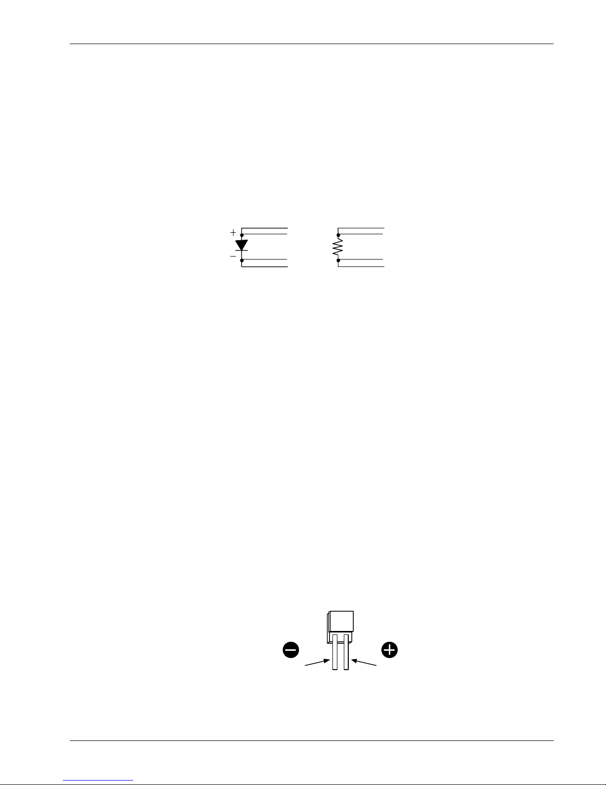
2.7.1.3 Sensor Mounting
Before installing a diode sensor, identify which lead is the anode and which is the cathode. When
viewed with the base down and with the leads towards the observer, the positive lead (anode) is on
the right and the negative lead (cathode) is on the left. The Lake Shore DT-470-SD silicon diode
sensor lead configuration is shown below. For other sensors, read the accompanying literature or
consult the manufacturer to ensure positive identification of sensor leads. Be sure the lead
identification remains clear even after installation of the sensor. It is also a good idea to record the
serial number and location of the sensor.
Installation 2-5
Cathode
DT-470-SD
Diode Sensor Leads
Anode

Lake Shore Model 321 Autotuning Temperature Controller User’s Manual
On the DT-470-SD, the base is the largest flat surface. It is sapphire with gold metallization over a
nickel buffer layer. The base is electrically isolated from the sensing element and leads, and all
thermal contact to the sensor should be made through the base. A thin braze joint around the
sides of the SD package is electrically connected to the sensing element. Contact to the sides
with any electrically conductive material must be avoided.
When installing the sensor, verify there are no electrical shorts or current leakage paths between
the leads or between the leads and ground. If IMI-7031 varnish or epoxy is used, it may soften
varnish-type lead insulations so that high resistance shunts appear between wires if sufficient
time for curing is not allowed. Teflon
®
spaghetti tubing is useful for sliding over bare leads when
the possibility of shorting exists. Also, avoid putting stress on the device leads and allow for the
thermal contractions that occur during cooling which could fracture a solder joint or lead if
installed under tension at room temperature.
For temporary mounting in cold temperature applications, a thin layer of Apiezon® N Grease may
be used between the sensor and sample to enhance the thermal contact under slight pressure.
The preferred method for mounting the DT-470-SD sensor is the Lake Shore CO Adapter.
CAUTION: Lake Shore will not warranty replace any device damaged by a user-designed clamp
If semi-permanent mountings are desired, the use of Stycast® epoxy can replace the use of
Apiezon
or damaged by solder mounting.
®
N Grease. (Note: Do not apply Stycast epoxy over the DT-470-SD package. Stress on
the sensor can cause shifts in the readings.) In all cases, the mounting of the sensor should be
periodically inspected to verify that good thermal contact to the mounting surface is maintained.
For the Model 321-02, Series PT-100 Platinum Sensors follow the same procedures for diode
type sensors. The difference is Platinum sensors have no lead polarity and some of the materials
used at cold temperatures will not tolerate the high temperature range of the Platinum sensor.
2.7.1.4 Measurement Errors Due To AC Noise
Poorly shielded leads or improperly grounded measurement systems can introduce AC noise into
the sensor leads. For diode sensors, the effect of the AC noise appears as a shift in the DC voltage
measurement due to the non-linear current/voltage characteristics of the diode. When this occurs,
the DC voltage measured will be too low and the corresponding temperature indication will be high.
The resulting measurement error can approach several tenths of a kelvin.
For Series PT-100 Platinum Sensors, the noise will not cause a DC shift, but it can still degrade the
accuracy of the measurement. To determine if this is a problem in your measurement system,
perform either of the two following procedures.
1. Place a capacitor across the diode to shunt the induced AC currents. The size of the capacitor
will depend on the frequency of the noise. If the noise is related to the power line frequency,
use a 10 µF capacitor. If AC-coupled digital noise is suspected (digital circuits or interfaces),
then use a capacitor between 0.1 to 1 µF. In either case, if the resultant DC voltage measured
is observed to increase, there is induced noise in your measurement system.
2. Measure the AC voltage across the diode with an AC voltmeter or oscilloscope. Note that most
voltmeters will not have the frequency response to measure noise associated with digital
circuits or interfaces (which operate in the MHz range). A thorough discussion of this potential
problem, and the magnitude of error which may result, is given in the paper “Measurement
System-Induced Errors In Diode Thermometry,” J.K. Krause and B.C. Dodrill, Rev. Sci. Instr. 57
(4), 661, April, 1986; which is available from Lake Shore upon request.
The potential for this type of error can be greatly reduced by connecting twisted leads (pairs)
between the controller and the diode sensors when an AC noise environment exists. We
recommend the use of Duo-Twist™ Cryogenic Wire, which features phosphor bronze wire, 32 or
36 AWG, twisted at 3.15 twists per centimeter (8 twists per inch). Duo-Twist wire is available from
Lake Shore. Refer to the Lake Shore Product Catalog or contact Lake Shore for further information.
2-6 Installation

Lake Shore Model 321 Autotuning Temperature Controller User’s Manual
2.7.2 Thermocouple (Model 321-04) Connections
The thermocouple input has a thermal block for connecting thermocouple wires. The positive and
negative terminals correspond to V+ and V– and should match the polarity of the thermocouple used.
Be sure to tighten the screw terminals carefully. Loose connections will result in unstable readings
and control. For additional information on thermocouple operation, refer to Paragraph 3.5.
2.7.2.1 Thermocouple Compensation
The thermocouple input has a thermal block for connecting thermocouple wires and for temperature
compensation. The thermocouple response curve tables within the instrument are normalized to the
ice point of water. Consequently, accurate readings can be obtained by one of two methods. An ice
bath with a reference junction can be used with the internal room temperature compensation turned
OFF. The more convenient method is to eliminate the reference junction with its associated ice bath
and use the internal electronic room temperature compensation by turning the internal
compensation ON.
2.7.2.2 Thermocouple Wire Types at Cryogenic Temperatures
Below are recommended thermocouple wire types for cryogenic temperatures. The ANSI color
code for thermocouples is red for the negative lead, while the type of thermocouple determines the
positive lead color: purple (Type E), black (Type J), yellow (Type K), and blue (Type T). For details
on thermocouples or other sensors, see the Lake Shore Temperature Sensor Guide.
Chromel™ vs. Gold with 0.03% or 0.07% Atomic Iron
Consists of Gold (Au) doped with 0.03*
or 0.07 atomic percent Iron (Fe) as the negative
(0.03% not currently sold by Lake Shore)
thermoelement and a Ni-Cr alloy (Chromel™) as the positive thermoelement. This thermocouple
has relatively high temperature sensitivity below 25 K, and usable sensitivity below 10 K. It is
widely used in cryogenic applications due to its relatively high thermoelectric sensitivity (>15 µV/K
above 10K). Recommended useful temperature range for the 0.03% Fe is 4 K to 325 K, and for
the 0.07% Fe is 1.4 K.
Type E (Chromel™-Constantan)
Type E is a thermocouple pair consisting of a Ni-Cr alloy (Chromel™) as the positive
thermoelement and a Cu-Ni alloy (Constantan) as the negative thermoelement. It has the highest
sensitivity of the three standard thermocouples (E, K and T) typically used for low temperature
applications: 8.5 µV/K at 20K. This thermocouple is best for temperatures down to 40 K. It is
recommended for oxidizing or inert environments. Do not use it in sulfurous or reducing
atmospheres, or environments that promote corrosion. Recommended useful temperature range
is 3 K to 475 K.
Type K (Chromel™-Alumel™)
Type K is a thermocouple pair consisting of a Ni-Cr alloy (Chromel™) as the positive
thermoelement and a Cu-Al alloy (Alumel™) as the negative thermoelement. It may be used in
inert environments, but not in sulfurous or reducing atmospheres, or environments that promote
corrosion. Sensitivity at 20K: 4.1 µV/K. Recommended useful temperature range is 3 K to 575 K.
Type T (Copper-Constantan)
Type T is a thermocouple pair consisting of Cu (Copper) as the positive thermoelement and a CuNi alloy (Constantan) as the negative element. It may be used in a vacuum as well as oxidizing,
reducing or inert environments down to 90 K. At temperatures below 80 K, the thermoelectric
properties of the positive thermoelement depend largely on the impurity of iron. The high thermal
conductivity of the copper element makes this thermocouple the least usable for cryogenic
applications. Sensitivity at 20 K: 4.6 µV/K.
Chromel™-CuFe (0.15%)
The Chromel™-Copper/Iron thermocouple consists of a Ni-Cr alloy (Chromel™) as the positive
thermoelement and a Copper/0.15% Iron alloy as the negative thermoelement. Sensitivity at
4.2K: >11 µV/K. Less expensive than Gold-Chromel™ thermocouples and physically stronger.
Recommended useful temperature range is 4 K to 300 K.
Installation 2-7
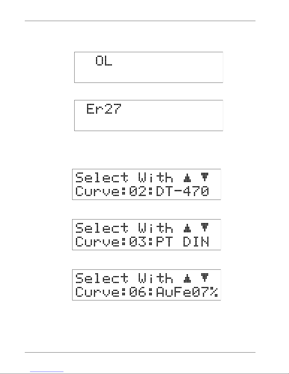
Lake Shore Model 321 Autotuning Temperature Controller User’s Manual
2.7.3 Sensor Input Error Messages
If an input signal from the sensor exceeding full scale is applied to the input leads, an overload
condition is present and is indicated by “OL” on the display, as shown below.
If no signal or a signal of the wrong polarity is present at the input leads, a Zero Error is indicated by
“Er27” on the display, as shown below.
2.8 SENSOR CURVE SELECTION
In order for the instrument to provide accurate temperature readings, it is necessary to select the
response curve that matches the sensor being used. To determine which curve is selected, press the
Curve key. The default curve for the Model 321-01 is DT-470 Curve 10, being the second selection in
the curve list built into the unit (refer to Table 2-2). This display is shown below.
The default curve for the Model 321-02 is Curve DIN-PT, being the third selection in the curve list built
into the unit (refer to Table 2-2). This display is shown below.
The default curve for the Model 321-04 is Curve AuFe07%, being the sixth selection in the curve list
built into the unit (refer to Table 2-2). This display is shown below.
To change the curve, press the Curve key, then press either the s (up) or t (down) key to increment
or decrement through the available curve selections. The curve numbers available are 0 through 12. To
accept a new curve number, press the Enter key, or press the Escape key to cancel. The standard
curves, with their curve number and temperature range, are given in Table 2-2. If a curve with the
wrong temperature coefficient slope is selected, the Model 321 will default to the lowest order curve of
the correct type.
2-8 Installation

Lake Shore Model 321 Autotuning Temperature Controller User’s Manual
Table 2-2. Sensor Curves
Curve No. Number of Lines Range (K) Abbreviation Description
00
01
02
03
04
05
06
07
08
09
10
11
12
31
31
31
31
88
31
31
31
31
31
31
1 – 325
1 – 325
1 – 325
14 – 800
2 - 475
1.4 – 325 *
4 – 325 *
3 – 850 *
3 – 1272 * †
3 – 670 *
DRC D
DRC E1
DT-470
Plat.
DT-470 *
AuFe07%
AuFe03%
Type E
Type K
Type T
User
SoftCal
DT-500 DRC Curve D
DT-500 DRC Curve E1
DT-400 Series Sensors Curve 10
Platinum DIN Curve
DT-400 Series Sensors Curve 10
Reserved
AuFe 0.07% vs. Chromel
AuFe 0.03% vs. Chromel
Type E
Type K
Type T
User Curve or Precision Option
SoftCal™ Curve
* Values are for thermocouples with compensation. Uncompensated, the thermocouple can use the full ±45 mV range.
† Display reading is limited to 999.9 in K. For higher readings, change units to °C.
Sensor curves available with the Model 321 include D Curve, E1 Curve, Curve 10, Platinum Curve (DIN
43760), various thermocouple curves, and a factory installed Precision Calibration Option for a
calibrated sensor.
D and E1 Curve. Users of older Lake Shore DT-500 Series Diode Sensors can still use the Model 321
when set to D-Curve (Domestic) or E1-Curve (Export).
Curve 10. The Lake Shore DT-470 Series silicon diodes follow the same standard temperature
response Curve 10. Consequently, all of the sensors in this series can be routinely interchanged with
one another. Curve 10 is programmed into all Lake Shore Temperature Controllers, Digital
Thermometers, and Temperature Transmitters. DT-470 Series silicon diode sensors are offered in five
bands of tracking accuracy, enabling sensors to be selected on the basis of both technical performance
and budgetary requirements.
Platinum Curve. Users of the Model 321-02 have the option of the standard platinum curve, or the
precision option. The standard platinum curve, which is detailed in Appendix C, conforms to
DIN 43760:1980; IEC 751:1983; and 1904:1984.
Thermocouple Curves. The curve selected should match the type of thermocouple being used.
User Curve. In addition to the standard curves, the Model 321 provides space for one user-defined
curve. Space for this user curve is provided as Curve Number 11 in the Model 321 (refer to Table 2-2).
This curve can be a custom curve developed by the Customer, a Precision Calibration Option Curve
purchased from Lake Shore (refer to Paragraph 2.9), or a curve purchased from another vendor. The
user defined curve can have up to 97 points plus two end points. The points can be loaded into the
controller using the serial interface, or if the Precision Calibration Option Curve is purchased from Lake
Shore, the curve can be entered at the factory. Chapter 4 of this manual describes user curve entry
using the serial interface.
SoftCal™ Curve. If the SoftCal™ feature of the Model 321 is used, the resulting SoftCal™ curve is
stored in curve location number 12. Refer to Table 2-2 and Paragraph 3.2.6 to use SoftCal™.
Installation 2-9

Lake Shore Model 321 Autotuning Temperature Controller User’s Manual
2.9 PRECISION CALIBRATION OPTION
The Precision Calibration Option is the easiest way to combine the additional performance of a Lake
Shore calibrated sensor with the Model 321 Temperature Transmitter. The Precision Calibration Option
is a read-only memory chip (PROM) with specific sensor calibration stored on it. The Precision
Calibration Option improves combined sensor/instrument accuracy to within ±0.25 K or better over the
calibrated temperature range of the sensor.
There are three types of precision options available for the Model 321. The Model 8000 Precision
Calibration Option generates the data table from a Lake Shore calibrated sensor. The maximum
number of data points is 99. A typical calibration precision option ranges between 30 and 40 points
depending on the sensor type and temperature range of the calibration. The data and accuracy of the fit
is supplied to the user as a separate document. This information can be entered by the user over the
serial interface.
Prior to shipment, Lake Shore can also generate a custom sensor response curve from the individual
sensor calibration as indicated in the above paragraph and store it in the Model 321 via the Model 8001
Precision Calibration Option. The data and accuracy of the fit is then supplied to the user as a
supplement to this manual.
The Model 8002 Precision Calibration Option is used when the customer already owns a Model 321
and wants the additional sensor calibration stored in the instrument. Lake Shore stores the calibration
data in a NOVRAM and sends the programmed IC to the customer. The IC is then installed in the
instrument by the customer. The user should be prepared to supply the Model 321 serial number at the
time of order.
The 8001-321 Precision Calibration Option is installed at Lake Shore when you order your instrument
with a calibrated sensor. If you order the instrument to be used with a Lake Shore calibrated sensor that
you already own, Lake Shore will need to know the model number and serial number of your sensor at
the time of order. The Model 8002-321 is for field installations of the Precision Calibration Option in an
existing Model 321.
2.10 HEATER SETUP
The heater output of the Model 321 is brought out the back panel as a Dual Banana Jack. A mating
connector is supplied. Current is driven from the HEATER (HI) connection to the HEATER (LO)
connection. A resistive heater load of 25Ω, 25 W should be connected between these two points.
The heater output is a 1 A on High range, 0.31 A on Low range, and does not have to be fused. The
Model 321 is designed to power a 25 Ω heater for maximum heater output. A larger heater resistance
may also be used but will result in a lower maximum power output. For example, the output compliance
voltage is 25 volts so that a 100 Ω heater resistance allows a maximum power output of 6.25 watts
2
[(25V)
/100 Ω].
If the heater load drops below ≈21 Ω, the output current will limit to prevent the instrument from
overheating. The maximum output current will drop with the heater resistance when the resistance is
below 21 Ω. The heater output is isolated from earth ground. To prevent heater noise coupling into the
measurement, do not allow the heater output to contact earth ground. For example, if the heater load is
20 Ω, the maximum output current is ≈0.90 A. If the heater output is shorted, the maximum output
current is ≈0.30 A.
NOTE: The front panel Heater % display is calculated, not measured. If heater resistance is not 25 Ω,
the display may not indicate actual heater output.
NOTE: The heater output is isolated from earth ground. To prevent heater noise coupling into the
measurement, do not allow the heater output to contact earth ground. Earth ground is provided
on the back panel for shielding purposes only.
NOTE: If the heater leads must be close to the sensor leads, wind (twist) them in such a manner that
they cross each other at ninety degrees.
2-10 Installation
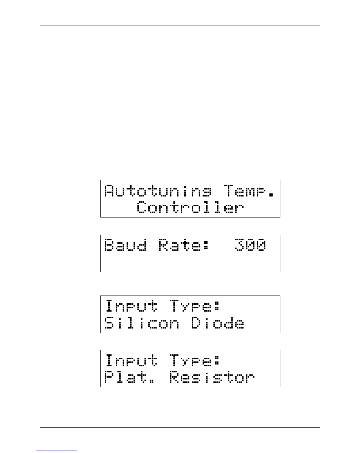
Lake Shore Model 321 Autotuning Temperature Controller User’s Manual
Within a cryostat, 30 gauge stranded copper lead wire (ND-30) is recommended for connection to the
heater. The heater leads should not run coincident with the sensor leads due to the possibility of
capacitive pick-up between the two sets of leads. If the heater leads must be close to the sensor leads,
wind (twist) them in such a manner that they cross at ninety degrees.
2.11 RACK MOUNTING
The Model 321 is shipped with plastic “feet” and is ready for use as a bench instrument. As an option,
the Model 321 can be installed in a standard 19 inch instrument rack. For information on the optional
Model 3022 Half-Rack Mounting Kit for a single controller, refer to Paragraph 5.3 and see Figure 5-4.
For information on the optional Model 3026 Dual Mounting Shelf for side-by-side mounting of two
controllers, refer to Paragraph 5.3 and see Figure 5-5.
2.12 POWER UP
The power up paragraph consists of a power up sequence in Paragraph 2.8.1. Power up (PUP)
Configuration is defined in Paragraph 2.8.2. Power up errors are explained in Paragraph 2.8.3.
2.12.1 Power Up Sequence
The following power up sequence occurs at power up.
1. The first display gives the name of the unit.
2. Next, the unit displays the current RS-232C Baud rate setting. The default setting is 300 Baud.
3. The temperature sensor input type is then displayed. The type of sensor depends on the model of
the instrument. A Model 321-01 will display the following message.
A Model 321-02 will display the following message.
Installation 2-11
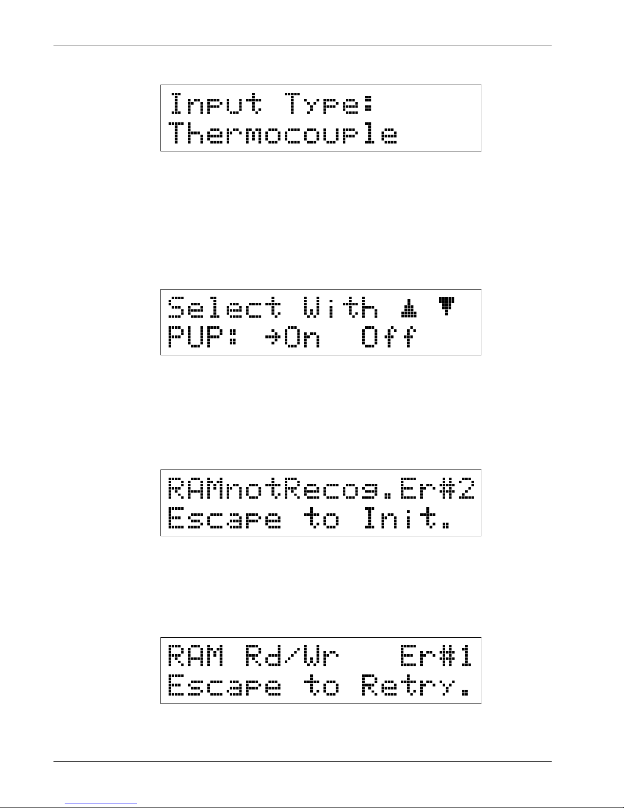
A Model 321-04 will display the following message.
Lake Shore Model 321 Autotuning Temperature Controller User’s Manual
4. The Model 321 then goes into normal operation showing the Temperature and Heater Range
(High, Low, or Off) setting on the first line and the Setpoint and Heater % power on the second
line. Refer to Chapter 3 for Model 321 operation.
2.12.2 Power Up (PUP) Configuration
A provision has been made to store a Power Up (PUP) configuration for the Model 321. This ensures
that it will power up to a user-defined state after power down. Parameters including heater range,
setpoint, gain, reset, units, and curve number are stored in non-volatile memory and preserved even
when the line cord is disconnected.
To view PUP status, press and hold the Enter key for ≈5 seconds. You will see the following display.
“On” indicates that the power up settings will change when settings on the instrument are made via
the front panel or over the remote interface. “On” is the default PUP condition.
“Off” indicates that updates to the power up memory are disabled and the instrument will power up in
the configuration it was in when the power up feature was turned off.
2.12.3 Power Up Errors
On power up, the Model 321 does a check of the internal memory. There are two potential error
messages. The first is usually recoverable, the second is not. The first error display is shown below.
This indicates than an attempt to read the internal non-volatile RAM for the Model ID was
unsuccessful. In some situations, this error can be corrected by the user by initializing the Model 321
memory. There are three methods that can be used to reinitialize the instrument: (1) Press the
Escape key when the error message is being displayed, (2) hold the Escape key down when the
instrument is off and then turning the instrument on, or (3) holding the Escape key down for more
than 5 seconds. Wait until a message is given before releasing the key.
The second error display is shown below.
This error message indicates that an attempt to write and then read the internal non-volatile RAM was
unsuccessful. This error is not correctable by the user. Please consult the factory.
2-12 Installation
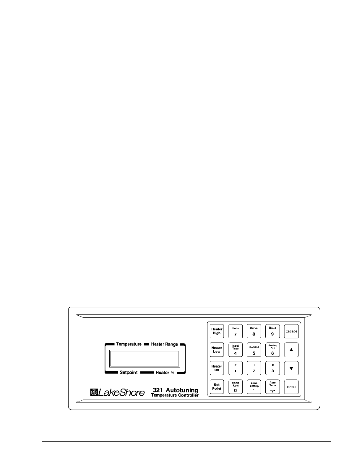
Lake Shore Model 321 Autotuning Temperature Controller User’s Manual
CHAPTER 3
OPERATION
3.0 GENERAL
This chapter describes Model 321 Temperature Controller operation. A definition of front panel
controls is provided in Paragraph 3.1. Thermometry related functions are described in Paragraph 3.2.
Control functions are described in Paragraph 3.3. Interface and miscellaneous functions are described
in Paragraph 3.4. Finally, thermocouple controller operation (Model 321-04 only) is described in
Paragraph 3.5.
3.1 DEFINITION OF FRONT PANEL CONTROLS
This paragraph provides a description of the front panel controls on the Model 321. The front panel
consists of two major sections: a description of the 20 front panel buttons in Paragraph 3.1.1, and a
description of the 2 row by 16 character LCD in Paragraph 3.1.2.
3.1.1 Front Panel Keypad Definitions
The buttons on the front panel are defined as follows. Note the following are abbreviated descriptions
of each button. A more detailed description of each function is provided in subsequent paragraphs.
Heater High Turns the heater on high: 25 Watts (maximum). Refer to Paragraph 3.3.1.
Heater Low Turns the heater on low: 2.5 Watts (maximum). Refer to Paragraph 3.3.1.
Heater Off Turns the heater off. Refer to Paragraph 3.3.1.
Set Point Permits the user to adjust the temperature setpoint. Refer to Paragraph 3.3.2.
Units Sets the controller to display temperature units in degrees kelvin (K) or Celsius (C),
or sensor units in volts (V), millivolts (mV), or ohms (Ω), depending on Model
Input Type Displays the currently selected sensor input type. Refer to Paragraph 3.2.1. This is
number. Refer to Paragraph 3.2.2.
a display only. To change the sensor input, refer to Paragraph 6.7. (The controller
must be recalibrated after changing the input type.) This button also has two press
and hold functions: Thermocouple Compensation and Display Filter. Refer to
Paragraphs 3.2.3 and 3.2.4 respectively.
P-321-1-1.bmp
Operation 3-1
Figure 3-1. Model 321 Front Panel

Lake Shore Model 321 Autotuning Temperature Controller User’s Manual
Ramp Rate Allows the user to set the rate at which the temperature setpoint increases or
Curve Used to select the sensor response curve. Refer to Paragraph 3.2.5.
decreases when the user changes the setpoint value. Refer to Paragraph 3.3.3.
SoftCal™ Permits the user to improve the accuracy of the silicon diode sensor by setting up a
special modification to the Standard Curve 10. Refer to Paragraph 3.2.6.
Zone Setting The user is able to enter up to 10 temperature zones where the controller will
automatically use preprogrammed PID settings and Heater Ranges. Refer to
Paragraph 3.3.6.
Baud If the Serial Interface is being used, the Baud Rate of the Model 321 may be
selected from 300 or 1200 by pressing this button. Refer to Paragraph 3.4.1.
Analog Out Use this button to set the scaling of the analog output. The default is 0 to 10 volts
corresponding to 0 to 1000 K. A user defined output scaling can also be specified.
Refer to Paragraph 3.4.2.
AutoTune The controller has the capability of automatically setting P, PI, or PID values. Refer
to Paragraph 3.3.4.
P For manual adjustment of controller gain (Proportional). Refer to Paragraph
I For manual adjustment of reset (Integral). Refer to Paragraph 3.3.5.2.
D For manual adjustment of rate (Derivative). Refer to Paragraph 3.3.5.3.
3.3.5.1.
Escape The Escape button is used to terminate a function without making changes to the
existing settings. Pressing and holding the Escape button for ≈5 seconds resets
the controller, returning most parameters to factory default values. Refer to
Paragraph 3.4.3.
s The up triangle (s) serves two functions. The first is to toggle between various
settings shown in the display. The second is to increment a numerical display.
s The down triangle (t) serves two functions. The first is to toggle between various
settings shown in the display. The second is to decrement a numerical display.
Enter The Enter button is used to accept changes made in the field display. Press and
hold the Enter button to gain access to the Power Up (PUP) configuration setup
display. Refer to Paragraph 3.4.4.
3.1.2 Two Row by Sixteen Character Liquid Crystal Display (LCD)
In normal operation, the two row by sixteen character display provides a temperature reading and
heater status on the top row and the current temperature setpoint and heater output status on the
bottom row. Other information is displayed when using the various functions on the keypad. Each
character is comprised of a 5 by 7 dot matrix. See Figure 3-2.
Temperature Reading
Temperature Setpoint
C-321-3-2.eps
3-2 Operation
Units:
K, C, V, mV, 99
Heater Range
Heater %
Figure 3-2. Definition of 2 by 16 Display
 Loading...