

Lake Shore 234, 234D User Manual

Rev. 1.7 P/N 119-026 1 March 2016
User’s Manual
Model 234
Temperature Transmitter
and
Model 234D
Temperature Transmitt er/Monitor
Includes Coverage for:
Model 2308-01 Benchtop Enclosure
Model 2308-12 VMEbus Rackmount Case
For Use with the Following Lake Shore Sensors:
Series CGR Carbon-Glass Resistance Temperature Sensors
Series CX Cernox™ Resistance Temperature Sensors
Series GR-200 Germanium Resistance Temperature Sensors
Lake Shore Cryotronics, Inc .
575 McCorkle Boulevard
Westerville, Ohio 43082-88 88 USA
E-Mail Addresses:
sales@lakeshore.com
service@lakeshore.com
Visit Our Website:
www.lakeshore.com
Fax: (614) 891-1392
Telephone: (614) 891-2243
Methods and apparatus disclosed and described herein have been developed solely on company funds of Lake
Shore Cryotronics, Inc. No government or other contractual support or relationship whatsoever has existed which in
any way affects or mitigates proprietary rights of Lake Shore Cryotronics, Inc. in these developments. Methods and
apparatus disclosed herein may be subject to U.S. Patents existing or applied for. Lake Shore Cryotronics, Inc.
reserves the right to add, impr ove, modify, or w ithdraw functions, de sign modifications, or products at any time w ithout
notice. Lake Shore shall not be liable for errors contained herein or for incidental or consequential damages in
connection with furnishing, performance, or use of this material.

Lake Shore Model 234/234D Us er’s Manual
A
LIMITED WARRANTY STATEMENT – WARRANTY PERIOD: ONE (1) YEAR
1. Lake Shore warran ts tha t t h is L a ke S hor e pr od uc t (t he “Product”) will be fre e fr om defects in materia ls
and workmanship for the Warranty Period specified above (the “Warranty Period”). If Lake Shore
receives notice of any such defects during the Warranty Period and the Product is shipped freight
prepaid, Lake Shore will, at its option, either repair or replace the Product if it is so defective without
charge to the owner for parts, service labor or associated customary return shipping cost. Any such
replacement for the Product may be either new or equivalent in performance to new. Replacement or
repaired parts will be warranted for only the unexpired portion of the original warranty or 90 days
(whichever is greater ) .
2. Lake Shore warrants the Product only if it has been sold by an authorized Lake Shore employee, sales
representative, dealer or original equipment manufa cturer (OEM).
3. The Product may contain remanufactured parts equivalent to new in performance or may have been
subject to incide ntal use.
4. The Warranty Peri od begins on the date the Product ships from Lake Shore’s plant.
5. This limited warr anty does n ot app ly to defect s in th e Prod uct re sulti ng from (a) imprope r or in adeq uate
maintenance, repair or calibration, (b) fuses, software and non-rechargeable batteries, (c) software,
interfacing, parts or other supplies not furnished by Lake Shore, (d) unauthorized modification or
misuse, (e) operation outside of the published specifications or (f) improper site preparation or
maintenance.
6. To the extent allowed by applicable law, the above warranties are exclusive and no other warranty or
condition, whether written or o ral, is expres sed or implie d. Lake shore specifically disclaim s any implied
warranties or conditions of merchantability, satisfactory quality and/or fitness for a particular purpose
with respect to the product. Some countries, states or provinces do not allow limitations on an implied
warranty, so the ab ov e limitation or exclu sion might not apply to y ou. T hi s wa rra nty gives you specif ic
legal rights and you might also have other rights that vary from country to country, state to state or
province to province.
7. To the extent allowed by applicable law, the remedies in this warranty statement are your sole and
exclusive remedies.
8. Except to the extent prohibited by applicable law, in no event will lake shore or any of its subsidiaries,
affiliates or supplier s be l ia ble fo r d ire c t, s p ecia l, i nc id en ta l, c on s eq uen t ial or ot her da m a ges ( in cl ud i ng
lost profit, lost data or downtime costs) arising out of the use, inability to use or result of use of the
product, whether based in warranty, contract, tort or other legal theory, and whether or not lake shore
has been advised of the possibility of such damages. Your use of the Product is entirely at your own
risk. Some countries, states and provinces do not allow the exclusion of liability for incidental or
consequential damages, so the above limitation may not apply to you.
9. Except to the extent allowed by applicable law, the terms of this limited warranty statement do not
exclude, restrict or modify, and are in addition to, the mandatory statutory rights applicable to the sale
of the product to you.
CERTIFICATION
Lake Shore certifies that this product has been inspected and tested in accordance with its published
specifications an d tha t th is pro d uct met its published spec if ic a ti ons a t the time of shipment. The accuracy and
calibration of this product at the time of shipment are traceable to the United States National Institute of
Standards and Technology (NIST); formerly known as the National Bureau of Standards (NBS), or to a
recognized natural st andard.
TRADEMARK ACKNOWLEDGEMENT
Manufacturers and sellers claim many designations as trademarks to distinguish their products. Where those
designations appear in this manual and Lake Shore was aware of a trademark claim, the designations appear
in initial capital letters with a ™ or
®
symbol.
Apiezon
®
is a trademark of Biddle Instrument s.
CalCurve™, Carbon-Glass™, Cernox™, Duo-Twist™, High-Temperature Cernox™, Quad-Lead™,
Quad-Twist™, Rox™, SoftCal™, and Therm ox™ are trademarks of Lake Shore Cryotronics, Inc.
Teflon
®
is a trademark of DuPont De Nemours.
Copyright © 1993, 1995, 1997, 1999, 2003-04, 2009, and 2016 by Lake Shore Cryotronics, Inc. All rights
reserved. No portion of this manual may be reproduced, stored in a retrieval system, or transmitted, in any
form or by any means, electronic, mechanical, photocopying, recording, or otherwise, without the express
written permission of Lake Shore.

Lake Shore Model 234/234D Us er’s Manual
Table of Contents i
TABLE OF CONTENTS
Chapter/Paragraph Title Page
1 INTRODUCTION .............................................................................. 1-1
1.0 General .......................................................................... 1-1
1.1 Model 234 General Descript ion ...................................... 1-1
1.2 Model 234D General Description ................................... 1-3
1.3 Model 2308-1 Enclosure Description.............................. 1-8
1.4 Model 2308-12 Case Descript ion ................................... 1-8
2 INSTALLATION ............................................................................... 2-1
2.0 General .......................................................................... 2-1
2.1 Inspection and Unpacking .............................................. 2-1
2.2 Repackaging For Shipment ............................................ 2-1
2.3 Sensor Installation Recom m endations ........................... 2-2
2.3.1 Sensor Mounting......................................................... 2-2
2.3.2 Connecting Leads To The Sensor .............................. 2-3
2.3.3 Four-Lead Measurements .......................................... 2-3
2.3.4 Proper Shielding Techniq ues ...................................... 2-4
2.4 Sensor Measurement ..................................................... 2-4
2.4.1 CalCurve ..................................................................... 2-5
2.5 Power Connections ........................................................ 2-5
3 OPERATION .................................................................................... 3-1
3.0 General .......................................................................... 3-1
3.1 PCB DIP Switch Settings ............................................... 3-1
3.2 Output to Temperature Conversion ................................ 3-2
3.3 Output to Log(R) Conversio n ......................................... 3-3
4 REMOTE OPERATION ................................................................... 4-1
4.0 General .......................................................................... 4-1
4.1 Serial Interface ............................................................... 4-1
4.1.1 Serial Interface Connect i ons ....................................... 4-1
4.1.2 Serial Interface Operati on ........................................... 4-2
4.1.3 QuickBasic Programming Considerations .................. 4-3
4.1.4 QuickBasic Sample Program ...................................... 4-4
4.2 Serial Interface Comman d S ummary ............................. 4-5
5 SERVICE ......................................................................................... 5-1
5.0 General .......................................................................... 5-1
5.1 General Troubleshooting ................................................ 5-1
5.1.1 No Output (On-Board LED Off) ................................... 5-1
5.1.2 Output Stops Before Reaching Upper Limit ................ 5-1
5.1.3 Resistance Readings Are Incorrect ............................ 5-1
5.1.4 Open Condition ........................................................... 5-1
5.2 Model 234 Connectors ................................................... 5-2
5.3 CalCurve Field Installation ............................................. 5-3

Lake Shore Model 234/234D Us er’s Manual
ii Table of Contents
Chapter/Paragraph Title Page
5.4 Calibration ..................................................................... 5-5
5.4.1 Required Equipment .................................................. 5-6
5.4.2 Preparation and General Test .................................... 5-6
5.4.3 Calibration With Range Switches ............................... 5-7
5.4.4 Calibration With Serial I nterface Commands ............. 5-9
5.4.5 Calibration Verification ..............................................5-11
6 OPTIONS AND ACCESSORIES .................................................... 6-1
6.0 General.......................................................................... 6-1
6.1 Enclosures ..................................................................... 6-1
6.2 Options .......................................................................... 6-1
6.3 Accessories ................................................................... 6-2
6.4 Wires ............................................................................. 6-2
6.5 Sensors ......................................................................... 6-3
6.6 Special Equipment ........................................................ 6-3
LIST OF ILLUSTRATIONS
Figure No. Title Page
1-1 Typical Model 234 Front Panel ................................................ 1-3
1-2 Model 234D Dimensions & Front Panel ................................... 1-4
1-3 Model 2308-1 Enclosure Physical Dimensions ........................ 1-9
1-4 Model 2308-12 Case Physical Dimensions .............................1-10
2-1 Typical Model 234 to Sensor Con nec tio ns ............................... 2-3
2-2 Typical Wall Plug-In Power Supply .......................................... 2-6
3-1 Model 234 DIP Switch (S1) Settings ........................................ 3-1
4-1 Serial I/O (RJ11) Connector Pin Definitions ............................. 4-1
4-2 Serial Interface Connect i ons .................................................... 4-2
5-1 Front Panel Connector Detail s ................................................. 5-2
5-2 VMEbus Connector Details ...................................................... 5-3
5-3 Model 234 PCB Layout ............................................................ 5-4
LIST OF TABLES
Table No. Title Page
1-1 Model 234 Specifications ......................................................... 1-5
1-2 Model 2308-12 Case Specifications ......................................... 1-8
3-1 Conversion Parameters f or Temperature in K .......................... 3-2
4-1 Serial Interface Specific ations .................................................. 4-1

Lake Shore Model 234/234D Us er’s Manual
Introduction 1-1
CHAPTER 1
INTRODUCTION
1.0 GENERAL
The Model 234 is designed an d manufactured in the USA by Lake S hore
Cryotronics, Inc. In general, references to the Model 234 applies to both the
Model 234 Transmitter and 234D Transmitter/Monitor. Specific references
are made where appropriate. This chapter provides a General Des cription of
the Model 234 in Paragraph 1.1, Model 234D General Description in
Paragraph 1.2, Model 2308-1 Enclosure Description in Paragraph 1.3, and
Model 2308-12 Case Descript ion in Paragraph 1.4.
We welcome comments on this m anual. Although we try to keep it error-free,
some may occur. To report an err or , describe it briefly and i nclude the
appropriate paragraph, figure, table, and page number. Send comments to
Lake Shore Cryotronics, At tn: Technical Publications, 575 McCorkle Blvd.,
Westerville, Ohio 43082-8888. This manual is subject to change without
notice.
1.1 MODEL 234 GENERAL DESCRIPTION
The Model 234 Temperature Transmitter sends temperature data from its
position near a sensor to a data acquisition channel or strip chart recorder.
A Model 234D also displays the temperature (or resistance).
The Model 234 operates with Cernox™, Carbon-Glass, Germanium, or other
resistance temperature sensors. The Lake Shore CGR Series Carbon-Glass
resistance temperature sensors are the best choice for a highly reproducible
sensor from 1.4 K to 325 K and above in magnetic fields up to 19 tesla or
higher. The Lake Shore GR Series Germanium resistance t emperature
sensors are recognized “secondary standard therm ometers” used in
temperature measurement u p to about 100 K for over 30 years. S ensitivity
for both devices increases rapidly with decreasing temperature (both devices
are classified according to their 4.2 K resistance value) .
Cernox, Carbon-Glass, and Germanium sensing elements are suspended in
a strain-free mounting which causes the thermal path through the connecting
leads, making measurement method and mounting critic al to accurate
temperature measurements.
The Model 234 excites the sensor with a constant voltag e of 10 mV or less
to minimize the effects of sensor self-heating at low temperatures.
Lake Shore Model 234/234D Us er’s Manual
1-2 Introduction
The Model 234 employs an analog control circuit to
maintain a constant voltage signal across the sensor.
A series of reference resistors convert the resulting
sensor current to a voltage. A microcontroller reads
the voltage with an A/D converter, calculates sensor
resistance, and converts t he resistance to temperature
by table interpolation (requires a CalCurve
™
for
temperature conversion). The sensor excitation
voltage is reversed each rea ding to compensate for
thermal voltages and offsets.
A current of 4 to 20 milliamps representing either
sensor resistance temperat ure or log transmits. The
transmitted current changes linearly with resist anc e
temperature or log. Output s cale depends on the
selected temperature range. Several switch selected
ranges are available. Hi ghest accuracy and sensitivity
are achieved when the output is set for a narrow
temperature band. A 0 to 20 mA output is also
available to convert output to a voltage scaled from
zero. A 500 ohm, ±0.02% output load resistor
produces the maximum full scale output of 10 volts.
A serial interface (operating at 9600 baud) can be
used for service purposes to read sensor resistance,
temperature, and configuration, install and review the
CalCurve, and calibrate the t r ansmitter.
A single +5 VDC supply power s Model 234 circuitry.
The outputs are isolated so s ev eral Model 234s can
run off the same supply without interference. +5 VDC
can also be supplied from the pins on the VME bus
connector.
The Model 234 is built on a standard A-Size VME
Card. It fits directly into a s i ngle height (3U) VME card
holder. The transmitter does not use the electrical bus
format, only its physical shape and power supply.
The Model 234 Temperature Transmitter is available
as a stand-alone unit or with one of two enclosures: a
Model 2308-1 single space enc l osure (included with
the Model 234D), or Model 2308-12 rackmount case
that holds 12 units. See Figure 1-1, and Tables 1-1
and 1-2.
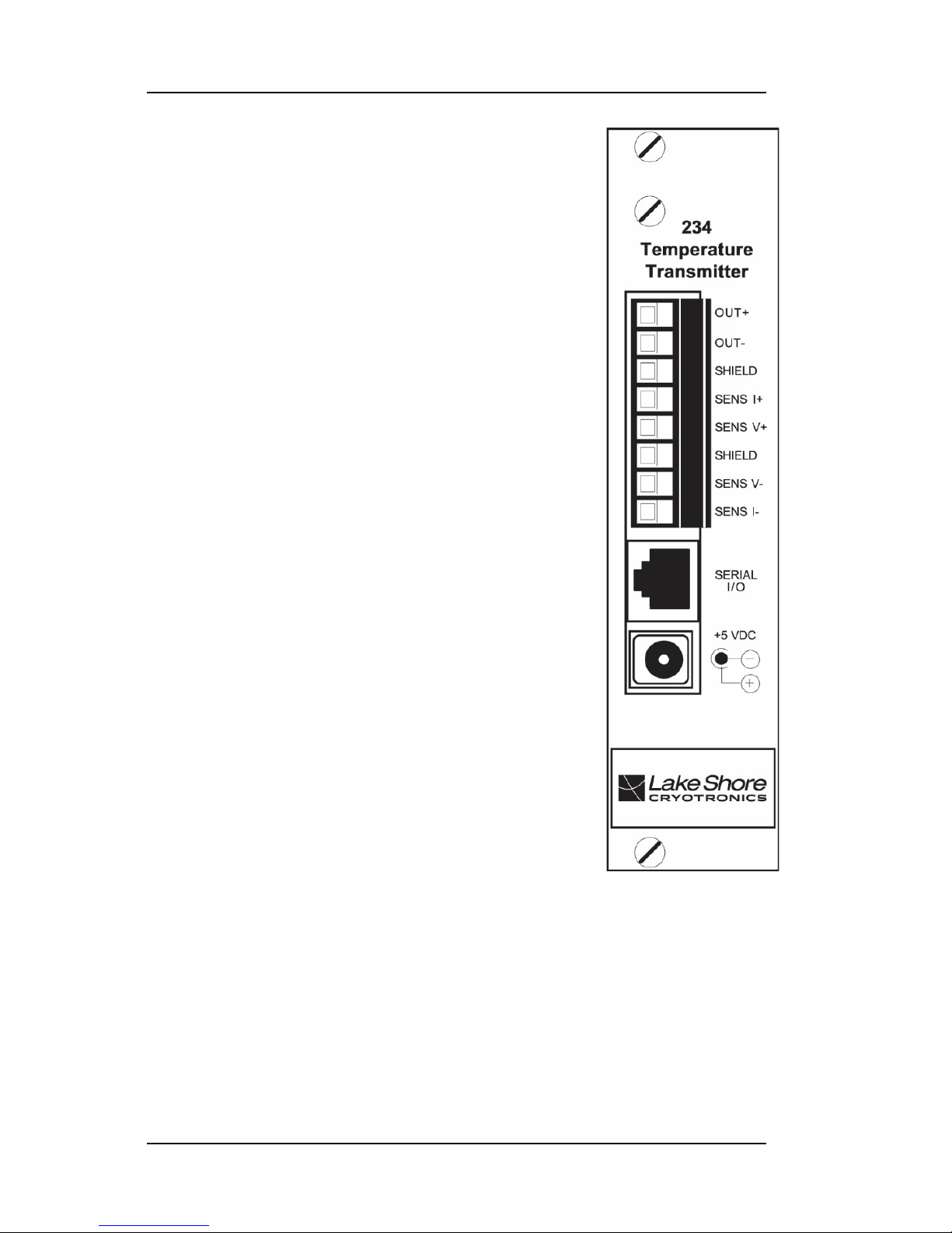
Figure 1-1. Typical
Model 234 Front Panel
(and Model 234D Rear Panel)

Lake Shore Model 234/234D Us er’s Manual
Introduction 1-3
1.2 MODEL 234D GENERAL DESCRIPTION
In addition to Model 234 feat ures, the Model 234D also pro vides local
display of the temperature or resistance of a single sensor via a 6-digit LED
Display. It maintains full transmitter capabilities, serial interface commands,
and curve format of the stand ar d Model 234. The display is upd ated at one
half the rate of the transmitter output.
Choose to display temperature in kelvin (K) or resistance in ohms (Ω) by
placing DIP switch S1 (see Figure 5-3), switch 7, to T (open) for temperature
or R (closed) for resistance. The temperature display is capable of 1 mK
resolution, but actual res ol ution is no better than the measurement resolution
listed in Table 1-1.
Place S1 Switch 7 to R (closed) to cause the display to read in ohms (Ω).
Note the display shows R, not log(R), present at the t r ansmitter output in this
configuration. The maximum resistance resolution is shown below. The
resistance display is capable of these resolutions, but t he actual resolution
is not better than the measurem ent resolution listed in T able 1-1.
Range
Display Resolution
Display
0 – 1 Ω
1 – 10 Ω
10 – 100 Ω
100 – 1 kΩ
1k – 10 kΩ
10k – 100 kΩ
100k – 300 kΩ
>≈400 kΩ
—
0.01 mΩ
0.1 mΩ
1 mΩ
10 mΩ
0.1 Ω
1 Ω
—
Short
1.00000 to 9.99999 Ω
10.0000 to 99.9999 Ω
100.000 to 999.999 Ω
1000.00 to 9999.99 Ω
10000.0 to 99999.9 Ω
100000 to 399999 Ω
Open
Model 234D front panel and dim ensions appear in Figure 1-2.

Lake Shore Model 234/234D Us er’s Manual
1-4 Introduction
Figure 1-2. Model 234D Front Panel and Dimensio ns

Lake Shore Model 234/234D Us er’s Manual
Introduction 1-5
Table 1-1. Model 234 Specificat ions
THERMOMETRY:
Number of Inputs: One
Measurement Type: Four-lead Differential
Sensor Type: Cernox, Carbon-Glass, or Germanium Resistance
Temperature Sensor
Sensor Units: Ohms (Ω)
Input Range: 1 Ω to 300 kΩ
Sensor Excitation: Constant voltage pinned at 5 mV or 10 mV
dependent on resistance range.
Update Rate: 4 readings / second (2 readings / second on Scale 0 only).
CalCurve Storage: 1 curve, factory or field loaded into EEPROM via
serial interface.
Example Lake Shore Sensor: CGR-1-1000 with 1.4L calibration
Temperature Range: 1.4 K – 325 K with CGR-1-1000
Standard Sensor Curve: Requires Calibrated Sensor and CalCurve
Typical Sensor Sensitivity: –700 Ω/K at 4.2 K –0.15 Ω/K at 77 K
–24 Ω/K at 10 K –0.02 Ω/K at 300 K
Measurement Scales, Excitation, Resolution, and Accuracy:
Sensor Excitation Accuracy
Scale Resistance (Ω) Voltage (mV) Resolution (Ω) +(% Rdg + Ω)
0 1 - 6 5 0.0003 0.5 + 0.0006
1 4.5 - 12.5 5 0.0001 0.1 + 0.0013
2 9 - 60 10 0.001 0.1 + 0.006
3 45 - 125 5 0.001 0.1 + 0.013
4 90 - 360 10 0.003 0.1 + 0.036
5 290 - 1.25 K 10 0.01 0.1 + 0.13
6 900 - 3.6 K 10 0.03 0.1 + 0.36
7 2.9 K - 12.5 K 10 0.1 0.1 + 1.3
8 9 K - 36 K 10 0.3 0.1 + 3.6
9 29 K - 300 K 10 6.8 0.5 + 30
Measurement Resolution Temperature Equivalence:
±0.04 mK at 4.2 K ±6.6 mK at 77 K
±0.12 mK at 30 K ±67 mK at 300 K
Electronic Measurement Equivalence Temperature Accuracy:
±2 mK at 4.2 K ±18 mK at 77 K
±8 mK at 10 K ±1.2 K at 300 K
Measurement Temperature Coefficient:
Measurement Units: 0.0125% of resistance reading per °C
Temperature Equivalence:
±0.18 mK/°C at 4.2 K - (0.126 Ω) ±18 mK/°C at 77.35 K - (0.0027 Ω)
±0.8 mK/°C at 10 K - (0.0185 Ω) ±100 mK/°C at 300 K - (0.0015 Ω)
Typical Sensor Calibration Accuracy:
±4 mK at 4.2 K ±45 mK at 77.35 K
±4 mK at 10 K ±250 mK at 300 K

Lake Shore Model 234/234D Us er’s Manual
1-6 Introduction
Table 1-1. Model 234 Specifications (Continued)
Typical CalCurve Target Accuracy:
±1 mK below 10 K ±100 mK 40 K - 100 K
±5 mK 10 K - 20 K ±1 K above 100 K
±25 mK 20 K - 40 K
Magnetic Field Use: Carbon-Glass: T ≥ 2 K and B ≤ 19 T.
Cernox: Recommended.
Germanium: Not Recommended.
OUTPUT:
Number of Outputs: One
Output Type: Current source, isolated from power source.
Output or sensor can be grounded, but not both.
Output Range: 4 - 20 mA or 0 - 20 mA
(for 0 - 10 V with 500 Ω, 0.02%, 25 PPM Resistor).
Output Compliance: 10 V (500 Ω maximum load).
Output Temperature Ranges:
0 - 10 K (Range 1) 0 - 100 K (Range 3) 0 - 300 K (Range 5)
0 - 20 K (Range 2) 0 - 200 K (Range 4) 75 - 325 K (Range 6)
4 – 20 mA Output (I/V OUT Switch in I Position):
Output Resolution:
Current: 1.22 µA (0.006% of full scale)
Temperature Equivalence:
0 - 10 K 0.8 mK 0 - 200 K 15.3 mK
0 - 20 K 1.5 mK 0 - 300 K 22.9 mK
0 - 100 K 7.6 mK 75 - 325 K 19.1 mK
Output Electronic Accuracy:
Current: ±5 µA (±0.025% of full scale)
Temperature Equivalence:
0 - 10 K 3.1 mK 0 - 200 K 62.5 mK
0 - 20 K 6.2 mK 0 - 300 K 93.7 mK
0 - 100 K 31.2 mK 75 - 325 K 78.1 mK
Output Temperature Coefficient:
Current: ±2 µA/°C (±0.01%/°C)
Temperature Equivalence:
0 - 10 K ±1 mK/°C 0 - 200 K ±20 mK/°C
0 - 20 K ±2 mK/°C 0 - 300 K ±30 mK/°C
0 - 100 K ±10 mK/°C 75 - 325 K ±25 mK/°C
0 – 20 mA Output (I/V OUT Switch in V Position,
0 – 10 V Out with 500 Ω, 0.02%, 25 PPM Load Resistor):
Output Resolution:
Voltage: 0.61 mV
Temperature Equivalence:
0 - 10 K 0.6 mK 0 - 200 K 12.2 mK
0 - 20 K 1.2 mK 0 - 300 K 18.3 mK
0 - 100 K 6.1 mK 75 - 325 K 15.2 mK

Lake Shore Model 234/234D Us er’s Manual
Introduction 1-7
Table 1-1. Model 234 Specificat ions (Continued)
Output Electronic Accuracy:
Voltage: ±4.5 mV (±0.025% of full scale ±0.02% resistor accuracy)
Temperature Equivalence:
0 - 10 K 4.5 mK 0 - 200 K 90.0 mK
0 - 20 K 9.0 mK 0 - 300 K 135.0 mK
0 - 100 K 45.0 mK 75 - 325 K 112.5 mK
Output Temperature Coefficient:
Voltage: ±1.25 mV/°C (±0.01%/°C + ±0.0025%/°C of load resistor)
Temperature Equivalence:
0 - 10 K ±1.2 mK/°C 0 - 200 K ±25 mK/°C
0 - 20 K ±2.5 mK/°C 0 - 300 K ±36 mK/°C
0 - 100 K ±12 mK/°C 75 - 325 K ±30 mK/°C
COMPUTER INTERFACE
(For full serial interface specifications, see Table 4-1.)
Type: RS-232C Electrical Format, Serial Three-Wire
Connector: RJ11 telephone type jack
MECHANICAL
Ambient temperature range: 15 °C to 35 °C (59 °F to 95 °F)
Power requirement: +5 (±0.25) VDC, 500 mA (234) / 750 mA (234D)
234 Size: 12.8 cm (5 in.) high, 18.5 cm (7.3 in.) deep, 3 cm (1.2 in.) wide
234D Size: 4.4 cm (1.7 in.) high, 23 cm (9 in.) deep, 14 cm (5.5 in.) wide
234 Mounting: Euroboard end panel and back plane. Transmitter
does not use electrical bus format, only its physical
shape and power supply.
NOTES
1. Product Specifications are subject to change without notice.
2. Total system temperature accuracy in a given temperature range is
the sum of the specifications given for input, calibration, and output.

Lake Shore Model 234/234D Us er’s Manual
1-8 Introduction
1.3 MODEL 2308-1 ENCLOSURE DESCRIPT ION
The Model 2308-1 Single Enclosure Case holds one Model 234 (see
Figure 1-4). It is the same enclos ure that houses the Model 234D.
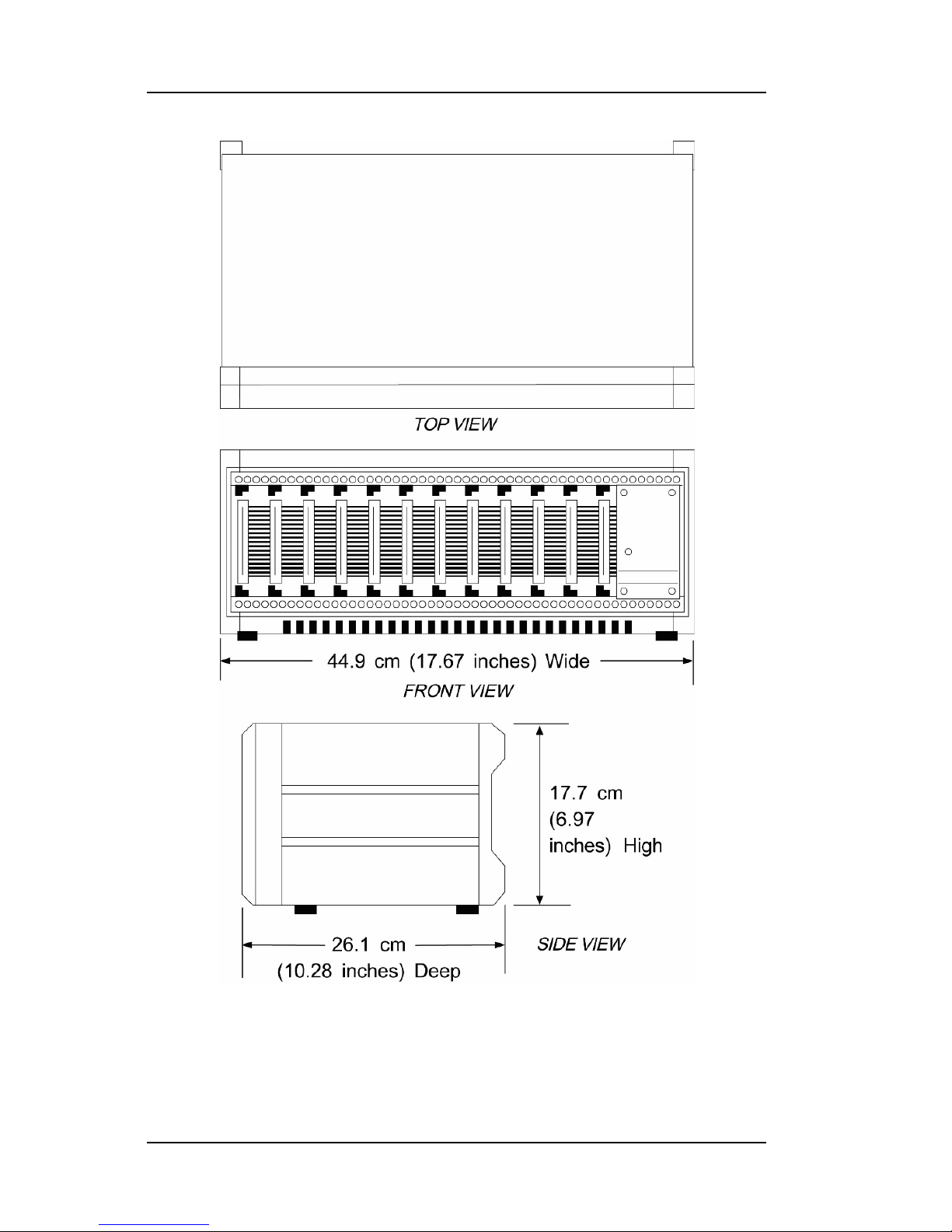
1.4 MODEL 2308-12 CASE DESCRIPTION
The Model 2308-12 VMEbus Rackm ount Case holds up to twelve Model 234
Temperature Transmitters. A +5 VDC power supply with universal input
comes with the case. See Table 1-2 and Figure 1-5. See Paragr aph 2.5 for
further information on the built-in power supply.
CAUTION: The Model 2308-12 bus is designed to power mul tiple
Model 234s and may not be used with standard VME cards.
Table 1-2. Model 2308-12 Case Specifications
No. of Card Slots: 12
Size: 45 cm (17.7 in.) wide × 18 cm (7 in.) high × 26 cm (10.3 in.) deep
Weight: 5.5 kilograms (12 pounds)
Output Voltage: +5 VDC, 100 mV Peak to Peak Ripple
Output Current: 6 amperes (maximum)
Input Power: Universal 85 to 265 VAC, 47 to 440 Hz, 60 Watts
Ambient Temp. Range: 15 to 35 °C (59 to 95 °F)
Lake Shore Model 234/234D Us er’s Manual
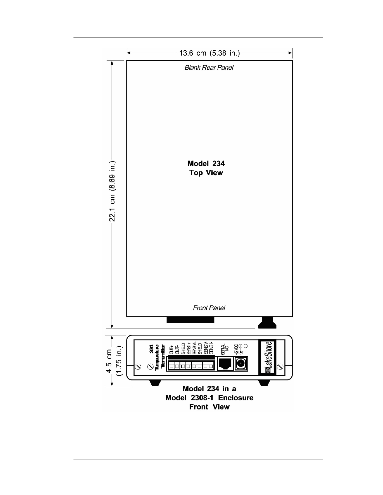
Introduction 1-9
Figure 1-3. Model 2308-1 Enclosure Physical Dimen sions
Lake Shore Model 234/234D Us er’s Manual
1-10 Introduction
Figure 1-4. Model 2308-12 Case Physical Dimensio ns

Lake Shore Model 234/234D Us er’s Manual
Installation 2-1
CHAPTER 2
INSTALLATION
2.0 GENERAL
This chapter covers Inspection and Unpacking in Paragraph 2.1, Repackaging
for Shipment in Paragraph 2.2, Sensor Installation Recom mendations in
Paragraph 2.3, Sensor Measurement in Paragraph 2.4, and Power
Connections in Paragraph 2.5.
2.1 INSPECTION AND UNPACKING
Inspect shipping containers for external damage. Mak e all claims for
damage (apparent or concealed) or partial loss of shipment in writing to Lake
Shore within five (5) days from receipt of goods. If damage or loss is
apparent, please notify th e s hipping agent immediatel y.
Open the shipping containers . Use the packing list include d with the system
to verify receipt of the inst rument, sensor, accessories , and manual. Inspect
for damage. Inventory all components supplied before discarding any
shipping materials. If there is freight damage to the instrument, file proper
claims promptly with the car rier and insurance company and notify Lake
Shore. Notify Lake Shore immediately of any missing parts. Lake Shore
cannot be responsible for any missing parts unless notif i ed within 60 days of
shipment. See the standard Lake Shore Warranty on the A Page
(immediately behind the tit le page).
2.2 REPACKAGING FOR SHIPMENT
To return the Model 120CS or acc es sories for repair or replacement, obtain
a Return Goods Authorizati on (RGA) number from Technical Service in the
United States, or from the authorized sales/service repr esentative from
which the product was purchased. Instruments ma y not be accepted without
a RGA number. When returning an instrument for service, Lake S hore must
have the following information before attempting any repair.
1. Instrument model and serial number .
2. User name, company, address, and ph one number.
3. Malfunction symptoms.
4. Descr i ption of system.
5. Returned Goods Authorization (RGA) number.
Repack the system in its origi nal c ontainer (if available). A ffix shipping labels
and FRAGILE warnings. Write R GA number on the outside of the container
or on the packing slip. If not available, consult Lake Shore for shipping and
packing instructions.
 Loading...