

Lake Shore 218S, 218, 218E User Manual
User’s Manual
Model 218
Temperature Monitor
Includes Coverage For:
Model 218S and Model 218E
Lake Shore Cryotronics, Inc.
575 McCorkle Blvd.
Westerville, Ohio 43082-8888 USA
Internet Addresses:
sales@lakeshore.com
service@lakeshore.com
Visit Our Website:
www.lakeshore.com
Fax: (614) 891-1392
Telephone: (614) 891-2243
Methods and apparatus disclosed and described herein have been developed solely on company funds of Lake
Shore Cryotronics, Inc. No government or other contractual support or relationship whatsoever has existed which in
any way affects or mitigates proprietary rights of Lake Shore Cryotronics, Inc. in these developments. Methods and
apparatus disclosed herein may be subject to U.S. Patents existing or applied for. Lake Shore Cryotronics, Inc.
reserves the right to add, improve, modify, or withdraw functions, design modifications, or products at any time
without notice. Lake Shore shall not be liable for errors contained herein or for incidental or consequential damages in
connection with furnishing, performance, or use of this material.
Revision 2.2 P/N 119-007 03 July 2012

Lake Shore Model 218 Temperature Monitor User’s Manual
1. Lake Shore warrants that this Lake Shore product (the “Product”) will
be free from defects in materials and workmanship for the Warranty
Period specified above (the “Warranty Period”). If Lake Shore receives
notice of any such defects during the Warranty Period and the Product
is shipped freight prepaid, Lake Shore will, at its option, either repair
or replace the Product if it is so defective without charge to the owner
for parts, service labor or associated customary return shipping cost.
Any such replacement for the Product may be either new or equivalent
in performance to new. Replacement or repaired parts will be
warranted for only the unexpired portion of the original warranty or 90
days (whichever is greater).
2. Lake Shore warrants the Product only if it has been sold by an
authorized Lake Shore employee, sales representative, dealer or
original equipment manufacturer (OEM).
3. The Product may contain remanufactured parts equivalent to new in
performance or may have been subject to incidental use.
4. The Warranty Period begins on the date of delivery of the Product or
later on the date of installation of the Product if the Product is installed
by Lake Shore, provided that if you schedule or delay the Lake Shore
installation for more than 30 days after delivery the Warranty Period
begins on the 31st day after delivery.
5. This limited warranty does not apply to defects in the Product resulting
from (a) improper or inadequate maintenance, repair or calibration, (b)
fuses, software and non-rechargeable batteries, (c) software,
interfacing, parts or other supplies not furnished by Lake Shore, (d)
unauthorized modification or misuse, (e) operation outside of the
published specifications or (f) improper site preparation or
maintenance.
6. TO THE EXTENT ALLOWED BY APPLICABLE LAW, THE
ABOVE WARRANTIES ARE EXCLUSIVE AND NO OTHER
WARRANTY OR CONDITION, WHETHER WRITTEN OR ORAL,
IS EXPRESSED OR IMPLIED. LAKE SHORE SPECIFICALLY
DISCLAIMS ANY IMPLIED WARRANTIES OR CONDITIONS OF
MERCHANTABILITY, SATISFACTORY QUALITY AND/OR
FITNESS FOR A PARTICULAR PURPOSE WITH RESPECT TO
THE PRODUCT. Some countries, states or provinces do not allow
limitations on an implied warranty, so the above limitation or
exclusion might not apply to you. This warranty gives you specific
legal rights and you might also have other rights that vary from
country to country, state to state or province to province.
7. TO THE EXTENT ALLOWED BY APPLICABLE LAW, THE
REMEDIES IN THIS WARRANTY STATEMENT ARE YOUR
SOLE AND EXCLUSIVE REMEDIES.
8. EXCEPT TO THE EXTENT PROHIBITED BY APPLICABLE
LAW, IN NO EVENT WILL LAKE SHORE OR ANY OF ITS
SUBSIDIARIES, AFFILIATES OR SUPPLIERS BE LIABLE FOR
DIRECT, SPECIAL, INCIDENTAL, CONSEQUENTIAL OR
OTHER DAMAGES (INCLUDING LOST PROFIT, LOST DATA
OR DOWNTIME COSTS) ARISING OUT OF THE USE,
INABILITY TO USE OR RESULT OF USE OF THE PRODUCT,
WHETHER BASED IN WARRANTY, CONTRACT, TORT OR
OTHER LEGAL THEORY, AND WHETHER OR NOT LAKE
SHORE HAS BEEN ADVISED OF THE POSSIBILITY OF SUCH
DAMAGES. Your use of the Product is entirely at your own risk.
Some countries, states and provinces do not allow the exclusion of
liability for incidental or consequential damages, so the above
limitation may not apply to you.
LIMITED WARRANTY STATEMENT
WARRANTY PERIOD: ONE (1) YEAR
LIMITED WARRANTY STATEMENT (Continued)
9. EXCEPT TO THE EXTENT ALLOWED BY APPLICABLE LAW,
THE TERMS OF THIS LIMITED WARRANTY STATEMENT DO
NOT EXCLUDE, RESTRICT OR MODIFY, AND ARE IN
ADDITION TO, THE MANDATORY STATUTORY RIGHTS
APPLICABLE TO THE SALE OF THE PRODUCT TO YOU.
CERTIFICATION
Lake Shore certifies that this product has been inspected and tested in
accordance with its published specifications and that this product met its
published specifications at the time of shipment. The accuracy and
calibration of this product at the time of shipment are traceable to the
United States National Institute of Standards and Technology (NIST);
formerly known as the National Bureau of Standards (NBS).
FIRMWARE LIMITATIONS
Lake Shore has worked to ensure that the Model 218 firmware is as free
of errors as possible, and that the results you obtain from the instrument
are accurate and reliable. However, as with any computer-based software,
the possibility of errors exists.
In any important research, as when using any laboratory equipment,
results should be carefully examined and rechecked before final
conclusions are drawn. Neither Lake Shore nor anyone else involved in
the creation or production of this firmware can pay for loss of time,
inconvenience, loss of use of the product, or property damage caused by
this product or its failure to work, or any other incidental or consequential
damages. Use of our product implies that you understand the Lake Shore
license agreement and statement of limited warranty.
FIRMWARE LICENSE AGREEMENT
The firmware in this instrument is protected by United States copyright
law and international treaty provisions. To maintain the warranty, the
code contained in the firmware must not be modified. Any changes made
to the code is at the user’s risk. Lake Shore will assume no responsibility
for damage or errors incurred as result of any changes made to the
firmware.
Under the terms of this agreement you may only use the Model 218
firmware as physically installed in the instrument. Archival copies are
strictly forbidden. You may not decompile, disassemble, or reverse
engineer the firmware. If you suspect there are problems with the
firmware, return the instrument to Lake Shore for repair under the terms
of the Limited Warranty specified above. Any unauthorized duplication
or use of the Model 218 firmware in whole or in part, in print, or in any
other storage and retrieval system is forbidden.
TRADEMARK ACKNOWLEDGMENT
Many manufacturers claim designations used to distinguish their products
as trademarks. Where those designations appear in this manual and Lake
Shore was aware of a trademark claim, they appear with initial capital
letters and the ™ or
Apiezon
®
is a trademark of Biddle Instruments.
®
symbol.
CalCurve™, Carbon-Glass™, Cernox™, Duo-Twist™, Quad-Lead™,
Quad-Twist™, Rox™, SoftCal™, and Thermox™ are trademarks of
Lake Shore Cryotronics, Inc.
Chromel™ and Alumel™ are trademarks of Hoskins Manufacturing
Company.
Formvar™ is a trademark of Monsanto Chemical Company.
®
MS-DOS
and Windows® are trademarks of Microsoft Corp.
NI-488.2™ is a trademark of National Instruments.
PC, XT, AT, and PS-2 are trademarks of IBM.
®
Stycast
is a trademark of Emerson & Cuming.
®
Teflon
is a trademark of DuPont De Nemours.
Copyright © 1998 – 2004, 2009 and 2012 by Lake Shore Cryotronics, Inc. All rights reserved. No portion of this manual
may be reproduced, stored in a retrieval system, or transmitted, in any form or by any means, electronic, mechanical,
photocopying, recording, or otherwise, without the express written permission of Lake Shore.
A

Lake Shore Model 218 Temperature Monitor User’s Manual
DECLARATION OF CONFORMITY
We: Lake Shore Cryotronics, Inc.
575 McCorkle Blvd.
Westerville OH 43082-8888 USA
hereby declare that the equipment specified conforms to the following
Directives and Standards:
Application of Council Directives: .............................. 73/23/EEC
89/336/EEC
Standard to which Conformity is declared: ................ EN 61010-1:2001
Overvoltage II
Pollution Degree 2
EN 61326 A2:2001
Class A
Annex B
Model Number: .......................................................... 218
Ed Maloof
Printed Name
Vice President of Engineering
Position
B

Lake Shore Model 218 Temperature Monitor User’s Manual
Electromagnetic Compatibility (EMC) for the Model 218 Temperature Monitor
Electromagnetic Compatibility (EMC) of electronic equipment is a growing concern worldwide.
Emissions of and immunity to electromagnetic interference is now part of the design and manufacture
of most electronics. To qualify for the CE Mark, the Model 218 meets or exceeds the generic
requirements of the European EMC Directive 89/336/EEC as a CLASS A product. A Class A product
is allowed to radiate more RF than a Class B product and must include the following warning:
WARNING: This is a Class A product. In a domestic environment, this product may
cause radio interference in which case the user may be required to take
The instrument was tested under normal operating conditions with sensor and interface cables
attached. If the installation and operating instructions in the User’s Manual are followed, there should
be no degradation in EMC performance.
Pay special attention to instrument cabling. Improperly installed cabling may defeat even the best
EMC protection. For the best performance from any precision instrument, follow the grounding and
shielding instructions in the User’s Manual. In addition, the installer of the Model 218 should consider
the following:
• Leave no unused or unterminated cables attached to the instrument.
• Make cable runs as short and direct as possible.
• Do not tightly bundle cables that carry different types of signals.
• Add the clamp-on ferrite filters (Part Number 9009-020) included with the connector kit to the
sensor input cables near the instrument rear panel.
adequate measures.
C

Lake Shore Model 218 Temperature Monitor User’s Manual
TABLE OF CONTENTS
Chapter/Paragraph Title Page
1 INTRODUCTION .................................................................................................................................... 1-1
1.0 GENERAL ........................................................................................................................... 1-1
1.1 MODEL 218 FEATURES .................................................................................................... 1-3
1.2 MODEL 218 SPECIFICATIONS ......................................................................................... 1-4
1.3 SAFETY .............................................................................................................................. 1-6
1.3.1 Handling Liquid Helium and Liquid Nitrogen ................................................................... 1-6
1.3.2 Safety Summary .............................................................................................................. 1-7
1.3.3 Safety Symbols ................................................................................................................ 1-7
2 SENSOR CONSIDERATIONS ............................................................................................................... 2-1
2.0 GENERAL ........................................................................................................................... 2-1
2.1 TEMPERATURE SENSOR SELECTION ........................................................................... 2-1
2.1.1 Temperature Range ......................................................................................................... 2-1
2.1.2 Sensor Sensitivity ............................................................................................................ 2-1
2.1.3 Environmental Conditions ................................................................................................ 2-1
2.1.4 Measurement Accuracy ................................................................................................... 2-2
2.1.5 Sensor Package .............................................................................................................. 2-2
2.2 CALIBRATED SENSORS ................................................................................................... 2-2
2.2.1 Traditional Calibration ...................................................................................................... 2-2
2.2.2 SoftCal™ .......................................................................................................................... 2-2
2.2.3 Standard Curves .............................................................................................................. 2-3
2.2.4 CalCurve™ ...................................................................................................................... 2-4
2.3 SENSOR INSTALLATION .................................................................................................. 2-4
2.3.1 Mounting Materials .......................................................................................................... 2-4
2.3.2 Sensor Location ............................................................................................................... 2-4
2.3.3 Thermal Conductivity ....................................................................................................... 2-4
2.3.4 Contact Area .................................................................................................................... 2-5
2.3.5 Contact Pressure ............................................................................................................. 2-5
2.3.6 Lead Wire ......................................................................................................................... 2-6
2.3.7 Lead Soldering ................................................................................................................. 2-6
2.3.8 Heat Sinking Leads .......................................................................................................... 2-6
2.3.9 Thermal Radiation ........................................................................................................... 2-6
2.3.10 Thermal EMF Compensation with Voltage Excitation ..................................................... 2-6
3 INSTALLATION ..................................................................................................................................... 3-1
3.0 GENERAL ........................................................................................................................... 3-1
3.1 INSPECTION AND UNPACKING ....................................................................................... 3-1
3.2 REPACKAGING FOR SHIPMENT ..................................................................................... 3-1
3.3 REAR PANEL DEFINITION ................................................................................................ 3-2
3.3.1 Line Input Assembly ........................................................................................................ 3-2
3.3.2 Sensor Inputs ...........................................................................................................
3.3.3 Terminal Block (Model 218S ONLY) ............................................................................... 3-7
3.3.4 Computer Interfaces ........................................................................................................ 3-8
4 OPERATION .......................................................................................................................................... 4-1
4.0 GENERAL ........................................................................................................................... 4-1
4.1 DISPLAY SCREEN DESCRIPTION ................................................................................... 4-1
4.2 KEYPAD DESCRIPTION .................................................................................................... 4-3
4.2.1 General Keypad Operation .............................................................................................. 4-4
4.3 TURNING POWER ON ....................................................................................................... 4-4
4.4 DISPLAY SETUP ................................................................................................................ 4-4
........ 3-4
Table of Contents i

Lake Shore Model 218 Temperature Monitor User’s Manual
TABLE OF CONTENTS (Continued)
Chapter/Paragraph Title Page
4.5 INPUT TYPE........................................................................................................................ 4-5
4.5.1 Optimizing the Update Rate ............................................................................................. 4-7
4.6 CURVE SELECT ................................................................................................................. 4-7
4.7 MATH ................................................................................................................................... 4-8
4.7.1 Max/Min ............................................................................................................................ 4-8
4.7.2 Linear ................................................................................................................................ 4-9
4.7.3 Filter ................................................................................................................................ 4-10
4.8 ANALOG OUTPUTS (MODEL 218S ONLY) ..................................................................... 4-11
4.8.1 Example of Low and High Analog Parameter Setting .................................................... 4-13
4.9 ALARMS SETUP AND OPERATION ................................................................................ 4-13
4.10 ALARM RESET ................................................................................................................. 4-15
4.11 RELAY SETUP (MODEL 218S ONLY) ............................................................................. 4-15
4.12 LOCKING THE KEYPAD ................................................................................................... 4-16
4.13 RESETTING MODEL 218 TO DEFAULTS ....................................................................... 4-16
5 SPECIAL FEATURES ............................................................................................................................ 5-1
5.0 GENERAL ............................................................................................................................ 5-1
5.1 FRONT PANEL CURVE ENTRY......................................................................................... 5-1
5.1.1 Curve Header Parameters ............................................................................................... 5-1
5.1.2 Curve Breakpoints ............................................................................................................ 5-2
5.1.3 Editing An Existing Curve ................................................................................................. 5-2
5.1.4 Entering A New Curve ...................................................................................................... 5-3
5.1.5 Erasing User Curves ........................................................................................................ 5-4
5.1.6 Viewing Standard Curves ................................................................................................. 5-4
5.1.7 Copying Curves ................................................................................................................ 5-4
5.2 SOFTCAL™ ......................................................................................................................... 5-5
5.2.1 SoftCal™ and Silicon Diode Sensors ............................................................................... 5-6
5.2.2 SoftCal™ Accuracy with Silicon Diode Sensors .............................................................. 5-7
5.2.3 SoftCal™ and Platinum Sensors ...................................................................................... 5-7
5.2.4 SoftCal™ Accuracy with Platinum Sensors ..................................................................... 5-8
5.2.5 Creating a SoftCal™ Calibration Curve ........................................................................... 5-8
5.3 DATA LOGGING ................................................................................................................. 5-9
5.3.1 Log Setup ......................................................................................................................... 5-9
5.3.2 Starting and Stopping Data Log ..................................................................................... 5-11
5.3.3 Viewing Logged Data ..................................................................................................... 5-11
5.3.4 Line Power Loss ............................................................................................................. 5-11
5.4 PRINTING .......................................................................................................................... 5-12
5.4.1 Printer Support ............................................................................................................... 5-12
5.4.2 Printer Connector and Cable .......................................................................................... 5-13
5.4.3 Printer Operation ............................................................................................................ 5-13
6 REMOTE OPERATION .......................................................................................................................... 6-1
6.0 GENERAL ............................................................................................................................ 6-1
6.1 IEEE-488 INTERFACE ........................................................................................................ 6-1
6.1.1 IEEE-488 Interface Settings ............................................................................................. 6-2
6.1.2 IEEE-488 Command Structure ......................................................................................... 6-2
6.1.3 Status Registers ............................................................................................................... 6-3
6.1.4 Example IEEE Setup and Program .................................................................................. 6-5
6.1.5 Notes On Using the IEEE Interface .................................................................................. 6-5
ii Table of Contents

Lake Shore Model 218 Temperature Monitor User’s Manual
TABLE OF CONTENTS (Continued)
Chapter/Paragraph Title Page
6.2 SERIAL INTERFACE .......................................................................................................... 6-8
6.2.1 Physical Connection ........................................................................................................ 6-8
6.2.2 Hardware Support ............................................................................................................ 6-8
6.2.3 Character Format ............................................................................................................. 6-9
6.2.4 Message Strings .............................................................................................................. 6-9
6.2.5 Message Flow Control ................................................................................................... 6-10
6.2.6 Changing Baud Rate ..................................................................................................... 6-10
6.2.7 Serial Interface Basic Programs .................................................................................... 6-11
6.2.8 Troubleshooting ............................................................................................................. 6-16
6.3 IEEE-488/Serial Interface Commands .............................................................................. 6-16
7 SERVICE ................................................................................................................................................ 7-1
7.0 GENERAL ........................................................................................................................... 7-1
7.1 GENERAL MAINTENANCE PRECAUTIONS .................................................................... 7-1
7.2 ELECTROSTATIC DISCHARGE ........................................................................................ 7-1
7.2.1 Identification of Electrostatic Discharge Sensitive Components ..................................... 7-1
7.2.2 Handling Electrostatic Discharge Sensitive Components ............................................... 7-2
7.3 FUSE DRAWER .................................................................................................................. 7-2
7.4 LINE VOLTAGE SELECTION ............................................................................................. 7-2
7.5 FUSE REPLACEMENT ...................................................................................................... 7-3
7.6 SENSOR INPUT CONNECTOR AND PINOUT ................................................................. 7-3
7.7 TERMINAL BLOCK (MODEL 218S ONLY) ........................................................................ 7-4
7.8 IEEE-488 INTERFACE CONNECTOR ............................................................................... 7-5
7.9 SERIAL INTERFACE CABLE AND ADAPTERS ................................................................ 7-6
7.10 TOP OF ENCLOSURE REMOVE AND REPLACE PROCEDURE .................................... 7-7
7.11 EPROM AND NOVRAM REPLACEMENT ......................................................................... 7-8
7.12 ERROR MESSAGES .......................................................................................................... 7-8
7.13 CALIBRATION PROCEDURE .......................................................................................... 7-10
7.13.1 Required Equipment List ............................................................................................... 7-10
7.13.2 Sensor Input Calibration Setup ...................................................................................... 7-10
7.13.3 Clear Calibration ............................................................................................................ 7-10
7.13.4 A/D Linearity Calibration ................................................................................................ 7-10
7.13.5 Zero Calibration ............................................................................................................. 7-11
7.13.6 2.5 Volt Input Gain Calibration ....................................................................................... 7-11
7.13.7 7.5 Volt Input Gain Calibration ....................................................................................... 7-11
7.13.8 10 µA Current Source Calibration .................................................................................. 7-11
7.13.9 250 Ω Input Gain Calibration ......................................................................................... 7-12
7.13.10 500 Ω Input Gain Calibration ......................................................................................... 7-12
7.13.11 7.5 kΩ Input Gain Calibration ........................................................................................ 7-12
7.13.12 5 kΩ Input Gain Calibration ........................................................................................... 7-13
7.13.13 Calibrate Input Group B ................................................................................................. 7-13
7.13.14 Analog Output Calibration and Test (Model 218S Only) ............................................... 7-13
7.13.15 Calibration Specific Interface Commands ..................................................................... 7-14
8 ACCESSORIES ...................................................................................................................................... 8-1
8.0 GENERAL ........................................................................................................................... 8-1
8.1 MODELS ............................................................................................................................. 8-1
8.2 OPTIONS ............................................................................................................................ 8-1
8.3 ACCESSORIES .................................................................................................................. 8-1
APPENDIX A – CURVE TABLES ................................................................................................................ A-1
Table of Contents iii

Lake Shore Model 218 Temperature Monitor User’s Manual
LIST OF ILLUSTRATIONS
Figure No. Title Page
1-1 Cryogenic Storage Dewar ............................................................................................................... 1-5
2-1 Silicone Diode Sensor Calibrations and CalCurve™ ...................................................................... 2-3
2-2 Typical Sensor Installation in a Mechanical Refrigerator ................................................................ 2-5
3-1 Model 218 Rear Panel .................................................................................................................... 3-2
3-2 Line Input Assembly ........................................................................................................................ 3-2
3-3 Model 218 Input Connector Pinouts ............................................................................................... 3-4
3-4 Terminal Block Connectors ............................................................................................................. 3-7
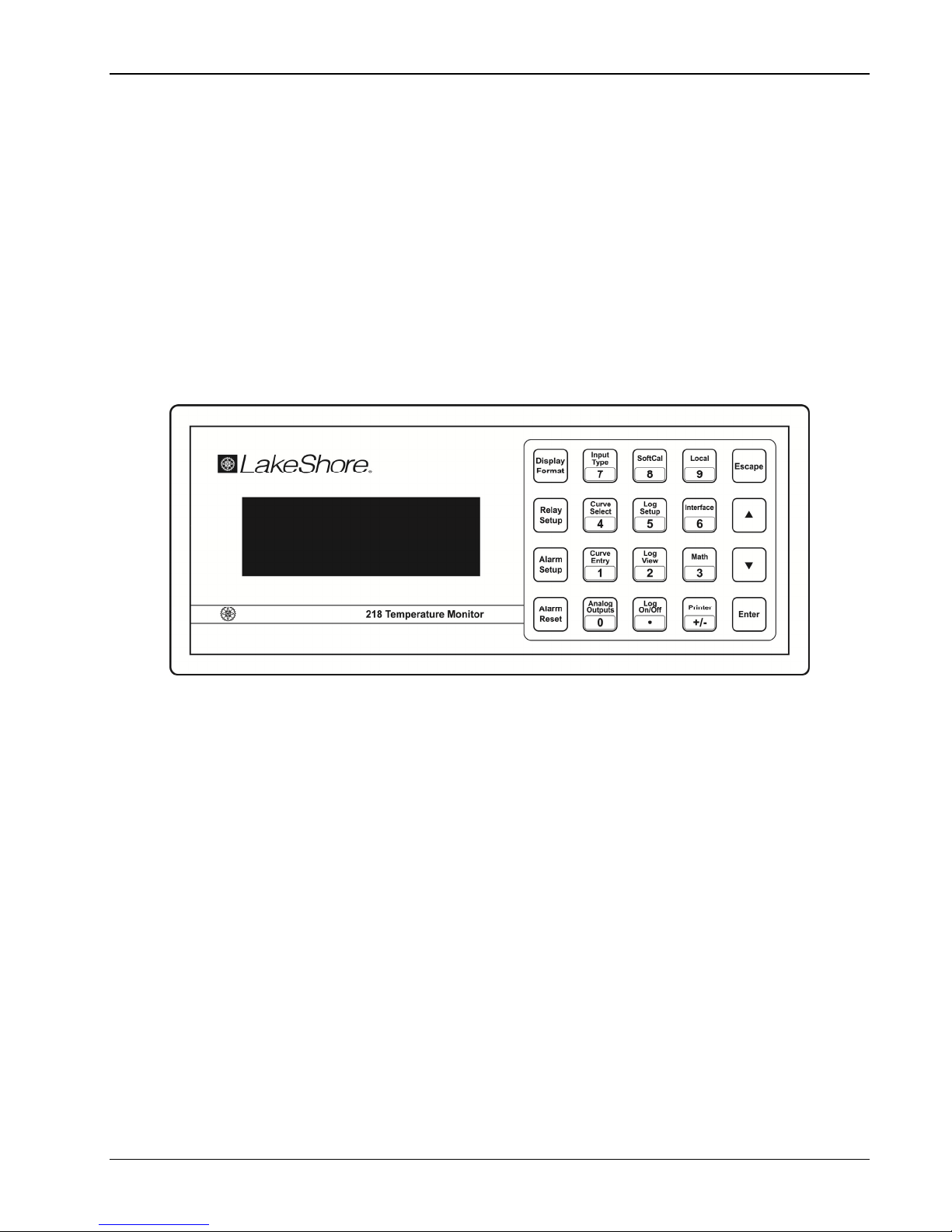
4-1 Model 218 Front Panel .................................................................................................................... 4-1
4-2 Model 218 Normal Display Screen Format ..................................................................................... 4-2
4-3 Example of Low and High Analog Parameter Setting .................................................................. 4-13
5-1 SoftCal™ Temperature Ranges for Silicon Diode Sensors ............................................................ 5-6
5-2 SoftCal™ Temperature Ranges for Platinum Sensors ................................................................... 5-7
5-3 Serial Port Details ......................................................................................................................... 5-13
6-1 Typical National Instruments GPIB Configuration from IBCONF.EXE ........................................... 6-7
7-1 Fuse Drawer .................................................................................................................................... 7-2
7-2 Power Fuse Access ........................................................................................................................ 7-2
7-3 Model 218 Input Connector Pinouts ............................................................................................... 7-3
7-4 Terminal Block Connectors ............................................................................................................. 7-4
7-5 IEEE-488 Rear Panel Connector Details ........................................................................................ 7-5
7-6 Serial Port Pinouts .......................................................................................................................... 7-7
7-7 Location of Internal Components .................................................................................................... 7-9
8-1 Model RM-1/2 Rack-Mount Kit ........................................................................................................ 8-3
8-2 Model RM-2 Dual Rack-Mount Kit .................................................................................................. 8-4
LIST OF TABLES
Table No. Title Page
1-1 Supported Lake Shore Sensors ...................................................................................................... 1-1
1-2 Model 218 Sensor Input Performance Chart .................................................................................. 1-4
3-1 AC Line Input Definitions ................................................................................................................ 3-3
4-1 Sensor Input Type Display Messages ............................................................................................ 4-6
4-2 Sensor Configuration Update Rates ............................................................................................... 4-7
4-3 Standard Curves Included in the Model 218 ................................................................................... 4-7
4-4 Model 218 Parameter Defaults ..................................................................................................... 4-16
5-1 Recommended Curve Parameters ................................................................................................. 5-1
5-2 Storage Capability Based on Readings per Record ....................................................................... 5-9
5-3 Serial Printer Interface Specifications ........................................................................................... 5-12
6-1 Sample BASIC IEEE-488 Interface Program .................................................................................. 6-6
6-2 Serial Interface Specifications ......................................................................................................... 6-9
6-3 Serial Interface Program Control Properties ................................................................................. 6-12
6-4 Visual Basic Serial Interface Program .......................................................................................... 6-13
6-5 Quick Basic Serial Interface Program ........................................................................................... 6-14
6-5 Model 218 Interface Commands by Function ............................................................................... 6-17
A-1 Standard DT-470 Diode Curve ...................................................................................................... A-1
A-2 Other Standard Diode and Platinum Curves ................................................................................. A-2
A-3 Standard DT-670 Diode Curve ...................................................................................................... A-2
iv Table of Contents

Lake Shore Model 218 Temperature Monitor User’s Manual
CHAPTER 1
INTRODUCTION
1.0 GENERAL
The Model 218 is an eight input temperature monitor that can be used with diode or resistive
temperature sensors. The measurement input was designed for the demands of cryogenic temperature
measurement. The monitor’s low noise, high resolution and wide operating range make it ideal for
noncryogenic applications as well.
There are two versions of the Model 218, the Model 218S and Model 218E. Both versions have the
same sensor measurement and display capabilities but include different interfaces.
The Model 218S has many interface features intended for system integration and automated data
collection that make it useful for cryogenic and noncryogenic applications. The Model 218S includes
two computer interfaces, IEEE-488 and serial. Data logging memory and printer capability are included
to help automate data collection. Two analog voltage outputs, an alarm feature and eight relays
enhance system integration.
The Model 218E is configured to have a lower selling price but maintains the same level of
performance. It includes a serial computer interface, data logging memory and printer capability. The
alarm feature is also present on the Model 218E, but there are no relays. The 218E has all the features
and specifications of the 218S except IEEE-488 interface, analog voltage outputs and relays.
Introduction 1-1

Lake Shore Model 218 Temperature Monitor User’s Manual
Table 1-1. Supported Lake Shore Sensors 1
Type Model Temp. Range
Diodes
Silicon Diode DT-670-SD 1.4 K to 500 K
Silicon Diode DT-670E-BR 30 K to 500 K
Silicon Diode DT-414 1.4 K to 375 K
Silicon Diode DT-421 1.4 K to 325 K
Silicon Diode DT-470-SD 1.4 – 475 K
Silicon Diode DT-471-SD 10 K to 500 K
GaAIAs Diode TG-120-PL 1.4 K to 325 K
GaAIAs Diode TG-120-PL 1.4 K to 325 K
GaAIAs Diode TG-120-SD 1.4 K to 500 K
Positive Temperature Coefficient RTDs
100 Ω Platinum
100 Ω Platinum
PT-102/3 14 K to 873 K
PT-111 14 K to 673 K
Rhodium-Iron RF-800-4 1.4 K to 500 K
Rhodium-Iron RF-100T/U 1.4 K to 325 K
Negative Temperature Coefficient RTDs2
Cernox™ CX-1010 2 K to 325 K4
Cernox™ CX-1030-HT 3.5 K to 420 K
Cernox™ CX-1050-HT 4 K to 420 K
3,6
Cernox™ CX-1070-HT 15 K to 420 K3
Cernox™ CX-1080-HT 50 K to 420 K3
Germanium GR-200A/B-1000 2.2 K to 100 K4
Germanium GR-200A/B-1500 2.6 K to 100 K4
Germanium GR-200A/B-2500 3.1 K to 100 K4
Carbon-Glass CGR-1-500 4 K to 325 K5
Carbon-Glass CGR-1-1000 5 K to 325 K5
Carbon-Glass CGR-1-2000 6 K to 325 K5
Rox™ RX-102A 1.4 K to 40 K5
1 Sensors sold separately.
2 Single excitation current may limit the low temperature range of NTC resistors
3 Non-HT version maximum temperature: 325 K
4 Low temperature limited by input resistance range
5 Low temperature specified with self-heating error: < 5 mK
6 Low temperature specified with self-heating error: < 12 mK
3,6
1-2 Introduction

Lake Shore Model 218 Temperature Monitor User’s Manual
1.1 MODEL 218 FEATURES
PTC Resistor Measurements
The Model 218 can read up to eight 100 Ω, 1000 Ω PTC (positive temperature coefficient) or any
other PTC resistive sensors using their standard curves or individual calibrations. Platinum RTDs are
known for their wide range of operation and uniform sensitivity. The Model 218 can read Platinum
RTDs to achieve temperature readings greater than 1000 K (727 °C). Platinum RTDs sold by Lake
Shore are limited to 800 K (527 °C).
Diode Measurements
The Model 218 can read up to eight Lake Shore DT-470 or any other diode temperature sensor.
Diode sensors are easily interchangeable and provide a wide measurement range from 1.4 to 475 K.
Many diodes like the DT-470 follow a standard temperature response curve that may eliminate the
need for costly or time consuming individual calibration. The convenient SoftCal™ feature can be
used to improve the accuracy of less expensive DT-470 sensors.
NTC Resistor Measurements
The Model 218 can read up to eight NTC (negative temperature coefficient) resistor sensors using
their standard curves or individual calibrations. NTC resistor sensors are typically used in specialized
applications such as magnetic and radiation environments. In some applications, the constant current
excitation of the 218 may limit the useful range of NTC resistor sensors (refer to Table 1-2).
Configurable Sensor Inputs
The Model 218 has eight constant current sources (one for each input) that can be configured for a
variety of sensors. The inputs can be configured from the front panel or via computer interface and
are grouped in two sets of four. Each set of four inputs are configured for the same sensor type (i.e.
all 100 Ω Platinum or all Silicon Diodes, etc.).
Sensor Input Reading Capability
The Model 218 has two high resolution A/D converters to increase its update rate. It can read sensor
inputs more quickly than other scanning monitors because it does not have to wait for current source
switching. The result is 16 new readings per second allowing all inputs to be read twice each second.
Inputs can be turned off to obtain a higher reading rate on fewer sensors. All readings can be read
out of the instrument with the IEEE-488 interface. The serial interface can also be used to read all
readings if it is operated efficiently. The display is updated twice each second.
Temperature Response Curves
The Model 218 has standard temperature sensor response curves for silicon diodes and platinum
RTDs. It can support a wide variety of temperature sensors that do not have a standard curve
because a unique 200 point user curve can be stored for each of the eight inputs. CalCurves™ for
Lake Shore calibrated sensors can be stored as user curves. User curves can be entered from the
front panel or with a computer interface. The built in SoftCal™ algorithm can also be used to generate
improved curves for DT-470 diodes and platinum RTDs that are stored as user curves.
Configurable Display
The eight display locations on the Model 218 are user configurable. These locations can be used to
display a single readout for each of the eight inputs or for more than one readout for fewer inputs.
Sources for readout data are temperature units, sensor units and results of the math function. Input
number and data source are always displayed for convenience.
Introduction 1-3

Lake Shore Model 218 Temperature Monitor User’s Manual
1.2 MODEL 218 SPECIFICATIONS
Thermometry
Number of Inputs: 8
Input Configuration: Two groups of four. Each group must contain same input type
Measurement Type: Four-lead differential
Excitation: Eight constant current sources
Supported Sensors (temp. range): Silicon Diode, GaAlAs Diode, RTDs: 100 Ω Platinum, 1000 Ω Platinum,
Germanium, Carbon Glass, Cernox, ROX
Accuracy/Resolution: Refer to Table 1-2
Maximum Update Rate: 16 readings per second total
Standard Curves: DT-470, DT-670, CTI-C, DT-500D, PT-100, PT-1000
User Curves: Room for eight (one per input). 200 point maximum for each
Soft Cal™: Improves accuracy of DT-470 diode to ±0.25 K from 30 K to 375 K. Improves
accuracy of Platinum RTDs to ±0.25 K from 70 K to 325 K. Stored as user curves
Math: Maximum, Minimum, and Linear Equation
Filter: Averages 2 to 64 input readings
Front Panel
Display: 4 line by 20 character backlit LCD display
Number of input displays: 1 to 8
Display Units: K, C, V, Ω
Display Update Rate: All displayed inputs twice in one second
Temperature Display Resolution: 0.001° between 0° to 99.999°, 0.01° between 100°
Sensor Units Display Resolution: Sensor dependent, to 5 digits
Display Annunciators: Remote (R), Alarm (A), Data Logging (D), Max (>), Min (<), Linear (/)
Keypad: 20-Key membrane, numeric and specific functions
Front Panel Features: Front panel curve entry and keypad lock-out
Interface
IEEE-488.2 Interface (218S Only): SH1,AH1,T5,L4,SR1,RL1,PP0,DC1,DT0,C0,E1
Serial Interface: RS-232C Electrical, DE-9 Connector, 9600 BAUD
Printer Capability: Support for serial printer through serial interface. Used with Data Log parameters
Alarms:
Number: 16 – High and low for each input
Data Source: Temperature, sensor units, linear equation
Settings: Units, High Setpoint, Low Setpoint, Deadband, Latching or Non-Latching,
Audible on or off
Actuators: Display annunciator, beeper, relays (218S)
Relays (218S Only):
Number: 8
Contacts: Normally Open (NO), Normally Closed (NC), and Common (C)
Contact Rating: 30 VDC at 5 A
Operation: Each input may be configured to actuate any or all of the 8 relays. Relays
may be activated on high, low, or both alarms for any input, or manually
Corrected Analog Output (218S):
Scale: User selected
Range: ±10 V
Resolution: 1.25 mV
Accuracy: ±2.5 mV
Minimum Load: 1 kΩ
Data Logging
Readings: 1
to 8 per record
Operation: Store Data Log records in memory or send them to the printer. Users may
display, print, or retrieve stored data by computer interface
Data memory: Maximum of 1500 single reading records, non-volatile
General
Ambient Temperature: 15 to 35 °C at rated accuracy. 10 to 40 °C at reduced accuracy
Power Requirement: 100, 120, 220, 240VAC, +6% –10%, 50 or 60Hz, 18 VA
Size: 217 mm W × 90 mm H × 317.5 mm D (8.5 × 3.5 × 12.5 in.), half rack
Weight: 3 kilograms (6.6 pounds)
Approval: CE Mark (contact Lake Shore for availability)
to 999.99°, 0.1° above 1000°
1-4 Introduction

Lake Shore Model 218 Temperature Monitor User’s Manual
Introduction 1-5
Table 1-2. Model 218 Sensor Input Performance Chart
Sensor Type Silicon Diode GaAlAs Diode
100
Ω Platinum RTD
500
Ω Full Scale
1000
Ω Platinum RTD Cernox™ RTD
Temperature Coefficient Negative Negative Positive Positive Negative
Sensor Units Volts (V) Volts (V) Ohms (Ω) Ohms (Ω) Ohms (Ω)
Input Range 0 to 2.5 V 0 to 7.5 V 0 to 500 Ω 0 to 5000 Ω 0 – 7500 Ω
Sensor Excitation
(Constant Current)
10 µA ±0.01% 10 µA ±0.01% 1 mA ±0.3% 1 mA ±0.3% 10 µA ±0.01%
Display Resolution
(Sensor Units)
100 uV 100 uV 10 m
Ω 100 mΩ 100 mΩ
Example LSCI Sensor
DT-470-CO-13 with
1.4H Cal.
TG-120SD with 1.4H Cal. PT-103 with 14J Cal. PT-10012 with 1.4J Cal. CX-1050-SD with 4L Cal.
Temperature Range 1.4 – 475 K 1.4 – 475 K 30 – 800 K 30 – 800 K 3.5 – 400 K
Standard Sensor Curve LSCI Curve 10 Requires Calibration DIN 43760 Scaled from DIN 43670 Requires calibration
Typical Sensor
Sensitivity
-30 mV/K at 4.2 K
-1.9 mV/K at 77 K
-2.4 mV/K at 300 K
-2.2 mV/K at 475 K
-180 mV/K at 10 K
-1.25 mV/K at 77 K
-2.75 mV/K at 300 K
-2.75 mV/K at 475 K
0.19
Ω/K at 30 K
0.42
Ω/K at 77 K
0.39
Ω/K at 300 K
0.35
Ω/K at 675 K
0.33
Ω/K at 800 K
1.9
Ω/K at 30 K
4.2
Ω/K at 77 K
3.9
Ω/K at 300 K
3.3
Ω/K at 800 K
-770
Ω/K at 4.2 K
-1.5
Ω/K at 77 K
-0.1
Ω/K at 300 K
Measurement Resolution:
Sensor Units
Temperature Equivalence
20 uV
1 mK at 4.2 K
11 mK at 77 K
10 mK at 300 K
10 mK at 475 K
20 uV
1 mK at 10 K
16 mK at 77 K
10 mK at 300 K
10 mK at 475 K
2 m
Ω
10.6 mK at 30 K
10 mK at 77 K
10 mK at 300 K
10 mK at 675 K
10 mK at 800 K
20 m
Ω
10.6 mK at 30 K
10 mK at 77 K
10 mK at 300 K
10 mK at 800 K
50 m
Ω
1 mK at 4.2 K
33.3 mK at 77 K
500 mK at 300 K
Electronic Accuracy:
Sensor Units
Temperature Equivalence
±160 uV ±0.01% RDG
±11 mK at 4.2 K
±138 mK at 77 K
±88 mK at 300 K
±77 mK at 475 K
±160 uV ±0.02% RDG
±6 mK at 10 K
±300 mK at 77 K
±150 mK at 300 K
±110 mK at 475 K
±0.004
Ω ±0.02% RDG
±25 mK at 30 K
±18 mK at 77 K
±70 mK at 300 K
±162 mK at 675 K
±187 mK at 800 K
±0.06
Ω ±0.04% RDG
±40 mK at 30 K
±33 mK at 77 K
±135 mK at 300 K
±370 mK at 800 K
±0.1
Ω ±0.04% RDG
±1 mK at 4.2 K
±88 mK at 77 K
±1.144 K at 300K
Temperature Accuracy
including electronic
accuracy, CalCurve™
and calibrated sensor
±31 mK at 4.2 K
±193 mK at 77 K
±138 mK at 300 K
±177 mK at 475 K
±21 mK at 10 K
±390 mK at 77 K
±140 mK at 300 K
±210 mK at 475 K
±45 mK at 30 K
±38 mK at 77 K
±105 mK at 300 K
±262 mK at 675 K
±287 mK at 800 K
±60 mK at 30 K
±53 mK at 77 K
±170 mK at 300 K
±470 mK at 800 K
±9 mK at 4.2 K
1
±138 mK at 77 K
1
±1.284 K at 300K
1
Magnetic Field Use
Recommended for
T > 60 K & B < 3 T
Recommended for
T > 4.2 K & B < 5 T
Recommended for
T > 40 K & B < 2.5 T
Recommended for
T > 40 K & B < 2.5 T
Recommended for
T > 2 K & B < 19 T
1
Specified accuracy includes no effects of thermal EMF voltages. An error of 3 mΩ results from ea ch 1 µV of thermal EMF voltage. In well-designed systems, thermal EMF voltage should b e less than 10 µV.
2
No longer available from Lake Shore.


Lake Shore Model 218 Temperature Monitor User’s Manual
1.3 SAFETY
1.3.1 Handling Liquid Helium and Liquid Nitrogen
Liquid Helium (LHe) and liquid nitrogen (LN
the Model 218. Although LHe and LN
2
) may be used in conjunction with
2
are not explosive, there are certain
safety considerations when handling them.
1.3.1.1 Handling Cryogenic Storage Dewars
Operate all cryogenic containers (dewars) in accordance with manufacturer
instructions. Safety instructions are normally posted on the side of each
dewar. Keep cryogenic dewars in a well-ventilated place, protected from the
weather, and away from heat sources. Figure 1-1 shows a typical cryogenic
dewar.
MAGNETIC
LIQUIDLIQUID
HELIUMHELIUM
UPRIGHT
NON-
KEEP
NON-
FLAMMABLE
1.3.1.2 Liquid Helium and Nitrogen Safety Precautions
Transfer LHe and LN
and operate storage dewar controls in accordance
2
with manufacturer/supplier instructions. During transfer, follow all safety
precautions written on the storage dewar and recommended by the
manufacturer.
WARNING: Liquid helium is a potential asphyxiant and can cause rapid suffocation
without warning. Store and use in an adequately ventilated area. DO NOT
vent the container in confined spaces. DO NOT enter confined spaces where
gas may be present unless area is well-ventilated. If inhaled, remove to fresh
air. If not breathing, give artificial respiration. If breathing is difficult, give
oxygen. Get medical attention.
WARNING: Liquid helium can cause severe frostbite to exposed body parts. DO NOT
touch frosted pipes or valves. For frostbite, consult a physician
immediately. If a physician is unavailable, warm the affected parts with
water that is near body temperature.
Two essential safety aspects of handling LHe are adequate ventilation and eye and skin protection.
Although helium and nitrogen gases are non-toxic, they are dangerous because they replace air in
a normal breathing atmosphere. Liquid helium is an even greater threat because a small amount of
liquid evaporates to create a large amount of gas. Store and operate cryogenic dewars in open,
well-ventilated areas.
When transferring LHe and LN2, protect eyes and skin from accidental contact with liquid or the
cold gas issuing from it. Protect eyes with full face shield or chemical splash goggles; safety
glasses (even with side shields) are inadequate. Always wear special cryogenic gloves (Tempshield
Cryo-Gloves
®
or equivalent) when handling anything that is, or may have been, in contact with the
liquid or cold gas, or with cold pipes or equipment. Wear long sleeve shirts and cuffless trousers
long enough to prevent liquid from entering shoes.
Figure 1-1. Cryogenic
Storage Dewar
1.3.1.3 Recommended First Aid
Post an appropriate Material Safety Data Sheet (MSDS) obtained from the manufacturer/distributor
at every site that stores and uses LHe and LN
and first aid.
If a person exhibits symptoms of asphyxia such as headache, drowsiness, dizziness, excitation,
excessive salivation, vomiting, or unconsciousness, remove to fresh air. If breathing is difficult, give
oxygen. If breathing stops, give artificial respiration. Call a physician immediately.
If exposure to cryogenic liquids or cold gases occurs, restore tissue to normal body temperature
(98.6 °F) by bathing it in warm water not exceeding 105 °F (40 °C). DO NOT rub the frozen part,
either before or after rewarming. Protect the injured tissue from further damage and infection and
call a physician immediately. Flush exposed eyes thoroughly with warm water for at least
15 minutes. In case of massive exposure, remove clothing while showering with warm water. The
patient should not drink alcohol or smoke. Keep warm and rest. Call a physician immediately.
Introduction 1-7
. The MSDS specifies symptoms of overexposure
2
1.3.2 Safety Summary
Observe these general safety precautions during all phases of instrument operation, service, and
repair. Failure to comply with these precautions or with specific warnings elsewhere in this manual
violates safety standards of design, manufacture, and intended instrument use. Lake Shore
Cryotronics assumes no liability for Customer failure to comply with these requirements.
The Model 218 protects the operator and surrounding area from electric shock or burn, mechanical
hazards, excessive temperature, and spread of fire from the instrument. Environmental conditions
outside of the conditions below may pose a hazard to the operator and surrounding area.
• Indoor use.
• Altitude to 2000 m.
• Temperature for safe operation: 5 to 40 °C.
• Maximum relative humidity: 80% for temperature up to 31 °C decreasing linearly to 50% at 40 °C.
• Power supply voltage fluctuations not to exceed ±10% of the nominal voltage.
• Overvoltage category II.
• Pollution degree 2.
Ground The Instrument
To minimize shock hazard, connect the instrument chassis and cabinet to an electrical ground.
The instrument is equipped with a three-conductor AC power cable. Plug the power cable into an
approved three-contact electrical outlet or use a three-contact adapter with the grounding wire
(green) firmly connected to an electrical ground (safety ground) at the power outlet. The power jack
and mating plug of the power cable meet Underwriters Laboratories (UL) and International
Electrotechnical Commission (IEC) safety standards.
Ventilation
The instrument has ventilation holes in its top and bottom covers. Do not block these holes when
the intrument is turned on.
Do Not Operate In An Explosive Atmosphere
Do not operate the instrument in the presence of flammable gases or fumes. Operation of any
electrical instrument in such an environment constitutes a definite safety hazard.
Keep Away From Live Circuits
Operating personnel must not remove instrument covers. Refer component replacement and
internal adjustments to qualified maintenance personnel. Do not replace components with power
cable connected. Always disconnect power and discharge circuits before touching them.
Do Not Substitute Parts Or Modify Instrument
Do not install substitute parts or perform any unauthorized modification to the instrument. Return
the instrument to an authorized Lake Shore Cryotronics, Inc. representative for service and repair to
ensure that safety features are maintained.
Cleaning
Do not submerge instrument. Clean only with a damp cloth and mild detergent. Exterior only.
Lake Shore Model 218 Temperature Monitor User’s Manual
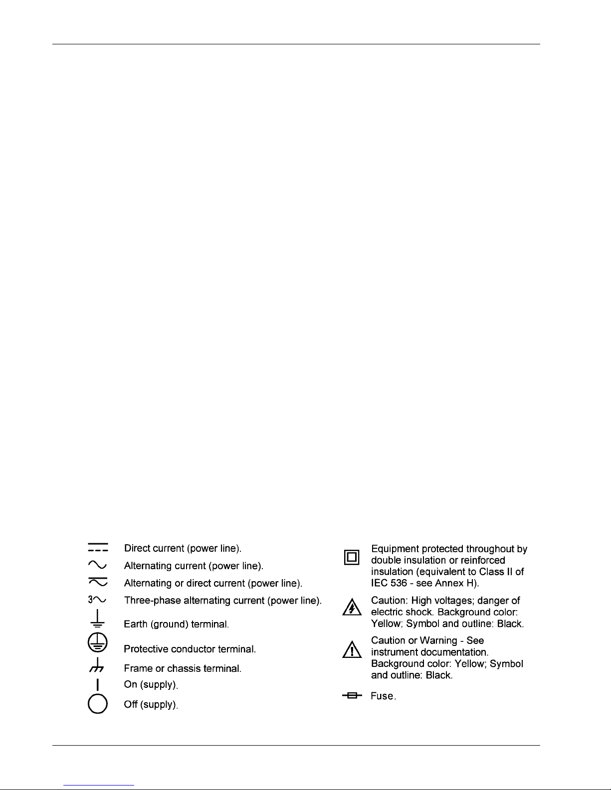
1.3.3 Safety Symbols
1-8 Introduction

Lake Shore Model 218 Temperature Monitor User’s Manual
CHAPTER 2
SENSOR CONSIDERATIONS
2.0 GENERAL
Selecting the proper sensor is vital to good temperature monitoring. This chapter covers Temperature
Sensor Selection in Paragraph 2.1, Calibrated Sensors in Paragraph 2.2, and Sensor Installation in
Paragraph 2.3. This chapter describes cryogenic applications, but many ideas apply to other
temperature measurements.
2.1 TEMPERATURE SENSOR SELECTION
This section covers general information about sensor selection. Find additional information on
temperature sensor characteristics and selection in the Lake Shore Temperature Measurement and
Control Catalog.
2.1.1 Temperature Range
The experimental temperature range must be known when choosing a sensor. Some sensors can be
damaged by temperatures that are too high or too low. Manufacturer’s recommendations should
always be followed. Sensor sensitivity is also dependent on temperature and can limit a sensors
useful range. It is important not to specify a range larger than necessary. If an experiment is being
done at liquid helium temperature and a very high sensitivity is needed for good measurement
resolution, that same resolution may not be required to monitor warm up to room temperature. Two
different sensors may be required to tightly cover the range from helium to room temperature, but
lowering the requirement on warm up may allow a less expensive, one sensor solution.
Another thing to consider when choosing a temperature sensor is that instruments like the Model 218
are not able to read some sensors over their entire temperature range. Lake Shore sells calibrated
sensors that operate down to 50 mK, but the Model 218 is limited to operation above 1 K in its
standard configuration.
2.1.2 Sensor Sensitivity
Temperature sensor sensitivity measures how much a sensor signal changes when the temperature
changes. It is important because so many measurement parameters relate to it. Resolution, accuracy,
and noise floor depend on sensitivity. Many sensors have different sensitivities at different
temperatures. For example, platinum sensor sensitivity is good at higher temperatures, but drops
sharply below 30 K. It may be difficult to determine if a sensor has adequate sensitivity over the
experimental temperature range. Table 1-2 lists sensor sensitivity translated into temperature
resolution and accuracy at different points. This is typical sensor response and can be used as a
guide to choose a sensor for the Model 218.
2.1.3 Environmental Conditions
Environmental factors such as high vacuum, magnetic field, corrosive chemicals, or even radiation
may limit effectiveness of some sensors. Lake Shore offers sensor packages that withstand
environmental factors found in typical cryogenic cooling systems.
Magnetic field experiments are very common. Field dependence is an important selection criteria for
temperature sensors used in these experiments. Table 1-2 states the field dependence of most
common sensors. The Lake Shore Temperature Measurement and Control Catalog includes detailed
field dependence tables along with specific data on other environmental factors when available.
Sensor Considerations 2-1

Lake Shore Model 218 Temperature Monitor User’s Manual
2.1.4 Measurement Accuracy
Temperature measurements have several sources of error. Account for errors induced by both the
sensor and the instrumentation when computing accuracy. The instrument has measurement error in
both reading the sensor signal and calculating a temperature using a temperature response curve.
Error results from the sensor comparison to a calibration standard; the sensor temperature response
shifts with time and repeated thermal cycling. Instrument and sensor makers specify these errors, but
some things help maintain good accuracy. For example, choose a sensor with good sensitivity in the
most critical temperature range, as sensitivity minimizes the effect of most error sources. Install the
sensor properly (Paragraph 2.3). Recalibrate the sensor and instrument periodically. Use a sensor
calibration appropriate for the accuracy requirement.
2.1.5 Sensor Package
There are many types of sensor packages which generally determine sensor size, thermal and
electrical contact to the outside, and sometimes limit temperature range. Some sensors may be
purchased as bare chips without a package. When different packages are available for a sensor,
consider the sensor mounting surface and how to heat sink the leads.
2.2 CALIBRATED SENSORS
It can be difficult to choose the right sensor, calibrate it, translate calibration data into a temperature
response curve understandable to the Model 218, and load the curve into the instrument. Lake Shore
offers a variety of calibration and curve loading services to fit different accuracy requirements and
budgets: Traditional Calibration in Paragraph 2.2.1, SoftCal™ in Paragraph 2.2.2, Standard Curves in
Paragraph 2.2.3, and the Lake Shore CalCurve™ Service in Paragraph 2.2.4.
2.2.1 Traditional Calibration
Calibration compares a sensor with an unknown temperature response to an accepted standard.
Lake Shore temperature standards are traceable to the U.S. National Institute of Standards and
Testing (NIST) or the National Physical Laboratory in Great Britain. These standards allow
Lake Shore to calibrate sensors from 50 mK to above room temperature. Calibrated sensors are
more expensive than uncalibrated sensors.
Calibrated temperature sensors are the most accurate available from Lake Shore. Errors from sensor
calibration are almost always smaller than error contributed by the Model 218. The Lake Shore
Temperature Measurement and Control Catalog has complete accuracy specs for calibrated sensors.
Calibrated sensors include measured test data printed and plotted, coefficients of a Chebychev
polynomial fitted to the data, and two tables of data points used as interpolation tables optimized for
accurate temperature conversion. The smaller table, called a breakpoint interpolation table, fits into
instruments like the Model 218 where it is called a temperature response curve. Install a curve into a
Model 218 through a CalCurve™ (Paragraph 2.2.4) or manually through the instrument front panel.
Note instrument specifications before ordering calibrated sensors. A calibrated sensor is required
when a sensor does not follow a standard curve if the user wishes to display in temperature.
Otherwise the Model 218 operates in sensor units like ohms or volts. The Model 218 may not work
over the full temperature range of some sensors. The Model 218 is limited to operation above 1 K or
more even with sensors that can be calibrated to 50 mK.
2.2.2 SoftCal™
SoftCal™ is a good solution for applications that do not require the accuracy of a traditional
calibration. The SoftCal™ algorithm uses the predictability of sensors that follow a standard curve to
improve individual sensor accuracy. A few known temperature points are required to perform
SoftCal™.
Lake Shore sells SoftCal™ calibrated sensors that include both the large interpolation table and the
smaller breakpoint interpolation table. A CalCurve™ (refer to Paragraph 2.2.4) or front panel curve
entry (refer to Paragraph 5.2) may be required to get the breakpoint table into a Model 218 where it is
called a temperature response curve.
2-2 Sensor Considerations
The Model 218 also performs SoftCal™ calibration. The user provides 1, 2, or 3 known temperature
reference points. Calibration range and accuracy depend on these points (Paragraph 5.2).
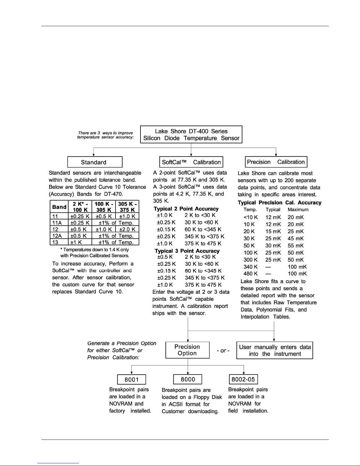
2.2.3 Standard Curves
Some types of sensors behave very predictably and a standard temperature response curve can be
created for them. Standard curves are a convenient and inexpensive way to get reasonable
temperature accuracy. Sensors with a standard curve are often used when interchangeability is
important. Some individual sensors are selected for their ability to match a published standard curve
and sold at a premium, but in general these sensors do not provide the accuracy of a calibrated
sensor. For convenience, the Model 218 has several standard curves included in firmware.
Lake Shore Model 218 Temperature Monitor User’s Manual
C-218-2-1.eps
Figure 2-1. Silicon Diode Sensor Calibrations and CalCurve™
Sensor Considerations 2-3

Lake Shore Model 218 Temperature Monitor User’s Manual
2.2.4 CalCurve™
The CalCurve™ service provides the user with a convenient way to get the temperature response
curve from Lake Shore’s calibrated sensors into instruments like the Model 218. It can be performed
at the factory when calibrated sensors and instruments are ordered together. The factory installed
CalCurve™ option is Model 8001 and should be ordered with the calibrated sensor.
A CalCurve™ can be done in the field when additional or replacement sensors are installed. Curve
data is loaded into some type of non-volatile memory that is installed into the instrument by the user.
In the case of the Model 218, the curve is loaded into a non-volatile memory chip which can be
installed into the instrument. The field installed version is a Model 8002 and it should be ordered with
the calibrated sensor.
Customers that have an RS-232C or IEEE-488 interface have another option in loading curves from
calibrated sensors. A Model 8000 includes the curve and a download program on a disk. The down
load program is a good idea if sensors are changed often. The Model 8000 should also be ordered
with the calibrated sensor.
2.3 SENSOR INSTALLATION
This section covers Mounting Materials in Paragraph 2.3.1, Sensor Location in Paragraph 2.3.2,
Thermal Conductivity in Paragraph 2.3.3, Contact Area in Paragraph 2.3.4, Contact Pressure in
Paragraph 2.3.5, Lead Wire in Paragraph 2.3.6, Lead Soldering in Paragraph 2.3.7, Heat Sinking Leads
in Paragraph 2.3.8, Thermal Radiation in Paragraph 2.3.9, and Thermal EMF Compensation with
Voltage Excitation in Paragraph 2.3.10.
For more detailed information, Lake Shore sensors ship with installation instructions that cover that
specific sensor type and package. The Lake Shore Temperature Measurement and Control Catalog
includes an installation section as well. Lake Shore also offers a line of cryogenic accessories. Many of
the materials discussed are available through Lake Shore and can be ordered with sensors or
instruments.
2.3.1 Mounting Materials
The high vacuum used to insulate cryostats is one consideration in choosing sensor mounting
materials. Choose materials with a low vapor pressure so they do not evaporate or out-gas and spoil
the vacuum insulation. Metals and ceramics do not have this problem, but greases and varnishes
must be checked. Another consideration is temperature extremes most sensors are exposed to. The
linear expansion coefficient of a material becomes important when temperature changes are so large.
Never try to permanently bond materials with linear expansion coefficients that differ by more than
three. Use a flexible mounting scheme or the parts will break apart, potentially damaging them. The
thermal expansion or contraction of rigid clamps or holders could crush fragile samples or sensors
that do not have the same coefficient.
2.3.2 Sensor Location
Positioning a sensor is less problematic if the entire load and sample holder are at the same
temperature. Unfortunately, this not the case in many systems. Temperature gradients (differences in
temperature) exist because there is seldom perfect balance between the cooling source and heat
sources. Even in a well-controlled system, unwanted heat sources like thermal radiation and heat
conduction through mounting structures can cause gradients. For best accuracy, position sensors
near the sample, so that little or no heat flows between the sample and sensor.
2.3.3 Thermal Conductivity
Thermal conductivity is the ability of heat to flow through a material. Copper and aluminum have good
thermal conductivity, while stainless steel does not. Non-metallic, electrically-insulating materials like
alumina oxide and similar ceramics have good thermal conductivity, while G-10 epoxy-impregnated
fiberglass does not. Sensor packages, cooling loads, and sample holders should have good thermal
conductivity to reduce temperature gradients. Surprisingly, connections between thermally conductive
mounting surfaces often have very poor thermal conductivity. Thermal conductivity can change with
temperature. Do not assume a heat sink grease that works well at room temperature and above will
do the same job at low temperatures.
2-4 Sensor Considerations
Lake Shore Model 218 Temperature Monitor User’s Manual
2.3.4 Contact Area
Thermal contact area greatly affects thermal conductivity because a larger area has more opportunity
to transfer heat. Even when the size of a sensor package is fixed, thermal contact area can be
improved with the use of a gasket material. A soft gasket material forms into the rough surface being
mated to increase the area of the two surfaces that is in contact. Good gasket materials are soft, thin
and have good thermal conductivity themselves. They must also withstand the environmental
extremes. Indium foil and cryogenic grease are examples.
2.3.5 Contact Pressure
When sensors are permanently mounted, the solder or epoxy used to hold the sensor acts as both
gasket and adhesive. Permanent mounting is not a good solution for everyone because it limits
flexibility and can potentially damage sensors. Much care should be taken not to over heat or
mechanically stress sensor packages. Less permanent mountings require some pressure to hold the
sensor to its mounting surface. Pressure will greatly improve the action of gasket material to increase
thermal conductivity and reduce thermal gradients. A spring clamp is recommended so that different
rates of thermal expansion don’t increase or decrease pressure with temperature change.
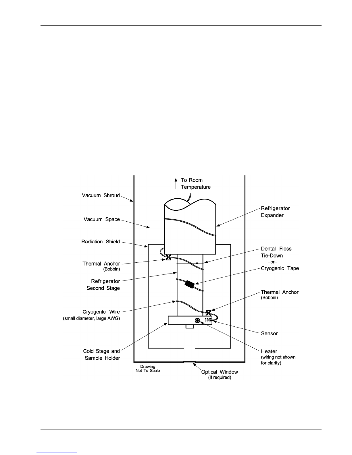
C-218-2-2.bmp
Figure 2-2 Typical Sensor Installation in a Mechanical Refrigerator
Sensor Considerations 2-5

2.3.6 Lead Wire
Different types of sensors come with different types and lengths of electrical leads. In general a
significant length of lead wire must be added to the sensor for proper heat sinking and connecting to
a bulk head connector at the vacuum boundary. The lead wire must be a good electrical conductor,
but a poor thermal conductor, or heat will transfer down the leads and change the temperature
reading of the sensor. Small 30 to 40 AWG wire made of an alloy like phosphor bronze is much better
than copper wire. Thin wire insulation is preferred and twisted wire should be used to reduce the
effect of RF noise if it is present. The wire used on the room temperature side of the vacuum
boundary is not critical so copper cable is normally used.
2.3.7 Lead Soldering
When additional wire is soldered to short sensor leads, care must be taken not to overheat the
sensor. A heat sink such as a metal wire clamp or alligator clip will heat sink the leads and protect the
sensor. Leads should be tinned before bonding to reduce the time that heat is applied to the sensor
lead. Solder flux should be cleaned after soldering to prevent corrosion.
2.3.8 Heat Sinking Leads
Sensor leads can be a significant source of error if they are not properly heat sinked. Heat will
transfer down even small leads and alter the sensor reading. The goal of heat sinking is to cool the
leads to a temperature as close to the sensor as possible. This can be accomplished by putting a
significant length of lead wire in thermal contact with every cooled surface between room temperature
and the sensor. Lead wires can be adhered to cold surfaces with varnish over a thin electrical
insulator like cigarette paper. They can also be wound onto a bobbin that is firmly attached to the cold
surface. Some sensor packages include a heat sink bobbin and wrapped lead wires to simplify heat
sinking.
Lake Shore Model 218 Temperature Monitor User’s Manual
2.3.9 Thermal Radiation
Thermal (black body) radiation is one of the ways heat is transferred. Warm surfaces radiate heat to
cold surfaces even through a vacuum. The difference in temperature between the surfaces is one
thing that determines how much heat is transferred. Thermal radiation causes thermal gradients and
reduces measurement accuracy. Many cooling systems include a radiation shield. The purpose of the
shield is to surround the load, sample, and sensor with a surface that is at or near their temperature
to minimize radiation. The shield is exposed to the room temperature surface of the vacuum shroud
on its outer surface, so some cooling power must be directed to the shield to keep it near the load
temperature. If the cooling system does not include an integrated radiation shield (or one cannot be
easily made), one alternative is to wrap several layers of super-insulation (aluminized mylar) loosely
between the vacuum shroud and load. This reduces radiation transfer to the sample space.
2.3.10 Thermal EMF Compensation with Voltage Excitation
Sensors used at low temperatures must operate with little power dissipated in the sensor. To keep
power low, the voltage across the sensor is kept low. Two major problems occur when measuring
small DC voltages. The first is external noise entering the measurement through the sensor leads
which is discussed with sensor setup. The second is the presence of thermal EMF voltages,
sometimes called thermocouple voltages, in the lead wiring. Thermal EMF voltages appear whenever
there is a temperature gradient across a piece of voltage lead. They can be canceled in the
measurement with a similar temperature gradient in the other voltage lead. Thermal EMF voltages
must exist because the sensor is almost never the same temperature as the instrument. Minimize
them by careful wiring, verifying voltage leads are symmetrical in the type of metal used and how they
are joined, and by keeping unnecessary heat sources away from the leads. Even in a well designed
system, thermal EMF voltages can be an appreciable part of a low voltage sensor measurement.
The Model 218 has no thermal correction algorithm. Other instruments automatically reverse the
current source polarity and average the positive and negative sensor readings to cancel the thermal
EMF voltage. Account for thermal EMF errors when estimating Model 218 measurement accuracy.
2-6 Sensor Considerations

Lake Shore Model 218 Temperature Monitor User’s Manual
CHAPTER 3
INSTALLATION
3.0 GENERAL
This chapter covers general Model 218 installation instructions: Inspection and Unpacking in
Paragraph 3.1, Repackaging for Shipment in Paragraph 3.2, and Rear Panel Definition in
Paragraph 3.3.
3.1 INSPECTION AND UNPACKING
Inspect shipping containers for external damage. Make all claims for damage (apparent or concealed)
or partial loss of shipment in writing to Lake Shore within five (5) days from receipt of goods. If damage
or loss is apparent, please notify the shipping agent immediately.
Open the shipping containers. Use the packing list included with the system to verify receipt of the
instrument, sensor, accessories, and manual. Inspect for damage. Inventory all components supplied
before discarding any shipping materials. If there is freight damage to the instrument, file proper claims
promptly with the carrier and insurance company and notify Lake Shore. Notify Lake Shore immediately
of any missing parts. Lake Shore cannot be responsible for any missing parts unless notified within 60
days of shipment. Refer to the standard Lake Shore Warranty on the A Page (behind the title page).
3.2 REPACKAGING FOR SHIPMENT
To return the Model 218, sensor, or accessories for repair or replacement, obtain a Return Goods
Authorization (RGA) number from Technical Service in the United States, or from the authorized
sales/service representative from which the product was purchased. Instruments may not be accepted
without a RGA number. When returning an instrument for service, Lake Shore must have the following
information before attempting any repair.
1. Instrument model and serial number.
2. User name, company, address, and phone number.
3. Malfunction symptoms.
4. Description of system.
5. Returned Goods Authorization (RGA) number.
Wrap instrument in a protective bag and use original spacers to protect controls. Repack the system in
the Lake Shore shipping carton (if available) and seal it with strong paper or nylon tape. Affix shipping
labels and FRAGILE warnings. Write the RGA number on the outside of the shipping container or on
the packing slip.
Installation 3-1
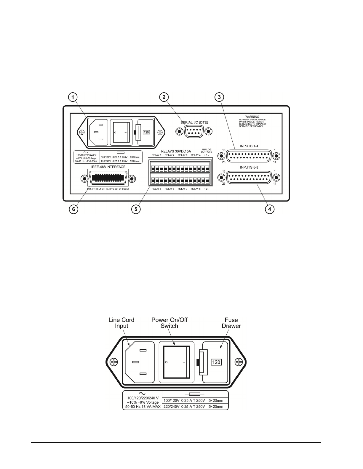
Lake Shore Model 218 Temperature Monitor User’s Manual
3.3 REAR PANEL DEFINITION
CAUTION: Verify that the AC Line Voltage shown in the window on the fuse holder is appropriate
for the intended AC power input. If the voltage setting is changed, remove and verify
the proper fuse is installed before inserting the power cord and turning on the
instrument. Always turn off the instrument before making any rear panel connections.
This is especially critical when making sensor to instrument connections.
F-218-3-1.eps
1. Line Input Assembly ................................................................... Paragraph 3.3.1
2. Serial I/O and Printer Connector ................................................ Paragraph 6.2
3. Sensor Input Connector for Inputs 1–4 ...................................... Paragraph 3.3.2.1
4. Sensor Input Connector for Inputs 5–8 ...................................... Paragraph 3.3.2.1
5. Terminal Block for Relays and Analog Outputs (218S Only) ..... Paragraph 3.3.3
6. IEEE-488 INTERFACE Connector (218S Only) ......................... Paragraph 6.1
Figure 3-1. Model 218 Rear Panel
3.3.1 Line Input Assembly
This section describes how to properly connect the Model 218 to line power. Please follow these
instructions carefully to ensure proper operation of the instrument and the safety of operators.
F-218-3-2.eps
3-2 Installation
Figure 3-2. Line Input Assembly

Lake Shore Model 218 Temperature Monitor User’s Manual
3.3.1.1 Line Voltage
The Model 218 has four different AC line voltages configurations so that it can be operated from
line power anywhere in the world. The nominal voltage and voltage range of each configuration is
shown in Table 3-1. (The recommended setting for 230 V operation is 240 V.)
Table 3-1. AC Line Input Definitions
Nominal Minimum Maximum
100 V 90 V 106 V
120 V 108 V 127 V
220 V 198 V 233 V
240 V 216 V 254 V
Verify that the AC line voltage indicator in the fuse drawer window shows the appropriate AC line
voltage before turning the instrument on. The instrument may be damaged if turned on with the
wrong voltage selected. Instructions for changing the line voltage configuration are given in
Paragraph 7.4.
3.3.1.2 Line Fuse and Fuse Holder
The line fuse is an important safety feature of the Model 218. If a fuse ever fails, it is important to
replace it with the value and type indicated on the rear panel for the line voltage setting. The letter
"T" on the fuse rating indicates that the instrument requires a time-delay or slow-blow fuse. Fuse
values should be verified any time line voltage configuration is changed. Instructions for changing
and verifying a line fuse are given in Paragraph 7.5.
3.3.1.3 Power Cord
The Model 218 includes a 3-conductor power cord that mates with the IEC 320-C14 line cord
receptacle. Line voltage is present on the two outside conductors and the center conductor is a
safety ground. The safety ground attaches to the instrument chassis and protects the user in case
of a component failure. A CE approved power cord is included with instruments shipped to Europe;
a domestic power cord is included with all other instruments (unless otherwise specified when
ordered). Always plug the power cord into a properly grounded receptacle to ensure safe
instrument operation.
The delicate nature of measurement being taken with this instrument may necessitate additional
grounding including ground strapping of the instrument chassis. In these cases the operators safety
should remain the highest priority and low impedance from the instrument chassis to safety ground
should always be maintained.
3.3.1.4 Power Switch
The power switch is part of the line input assembly on the rear panel of the Model 218 and turns
line power to the instrument On and Off. When the circle is depressed, power is Off. When the line
is depressed, power is On.
Installation 3-3
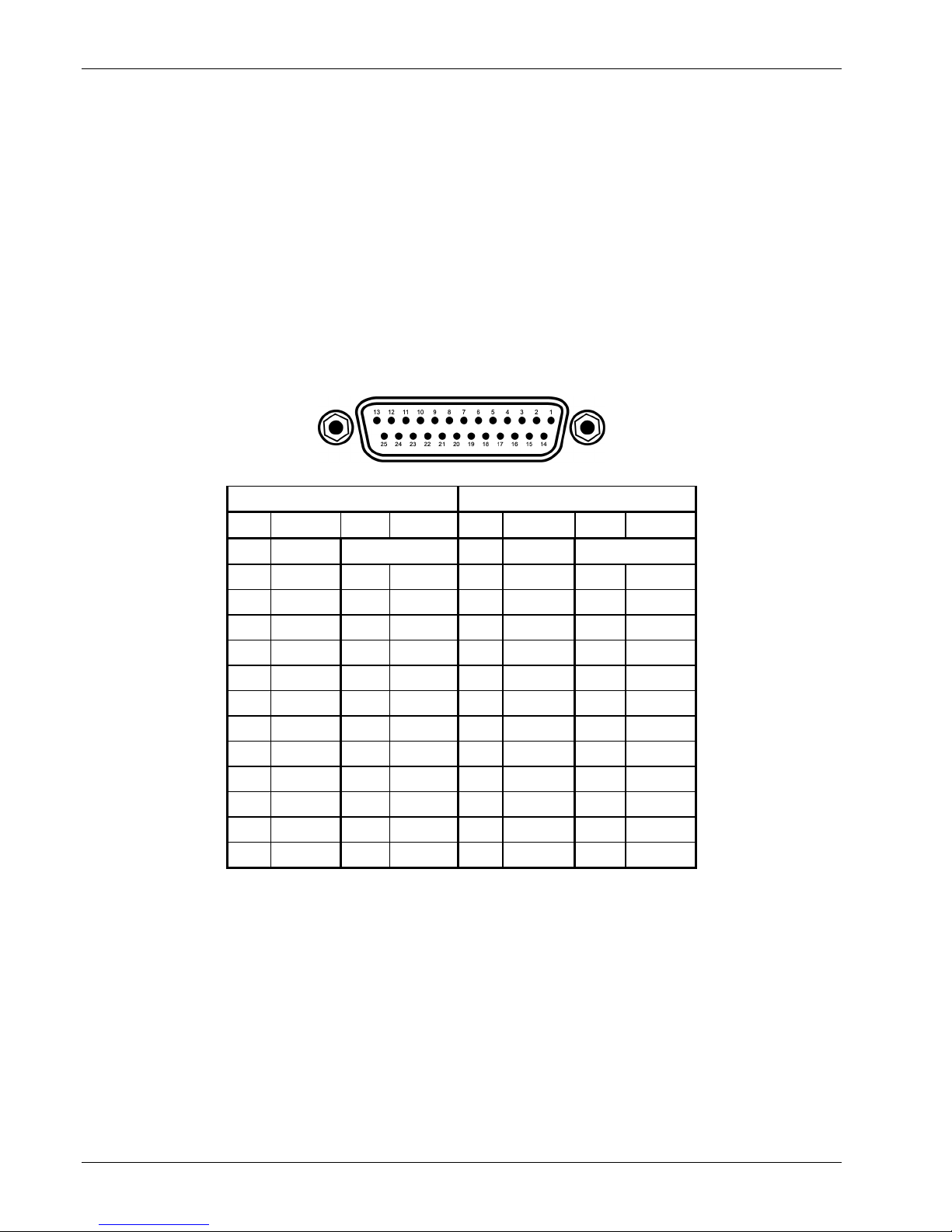
Lake Shore Model 218 Temperature Monitor User’s Manual
3.3.2 Sensor Inputs
This section covers Sensor Input Connector and Pinout in Paragraph 3.3.2.1, Sensor Lead Cable in
Paragraph 3.3.2.2, Grounding and Shielding Sensor Leads in Paragraph 3.3.2.3, Sensor Polarity in
Paragraph 3.3.2.4, Four-Lead Sensor Measurement in Paragraph 3.3.2.5, Two-Lead Sensor
Measurement in Paragraph 3.3.2.6, and Lowering Measurement Noise in Paragraph 3.3.2.7.
3.3.2.1 Sensor Input Connector and Pinout
This paragraph details how to connect sensors to the Model 218 inputs. The sensor inputs operate
with most resistive and diode sensors. Refer to Paragraph 4.5 to configure inputs for a sensor type
with software.
Disable unused sensor inputs with the Input Type key (Paragraph 4.5). It is possible for an overload
condition on one sensor to affect the reading on another in the same connector. Wire redundant
sensors in separate connectors for best reliability. Split fewer than eight sensors evenly between
connectors for best reading efficiency.
F218-3-3.bmp
Input Connector (Inputs 1-4) Input Connector (Inputs 5-8)
PIN DESC. PIN DESC. PIN DESC. PIN DESC.
1 NC 1 NC
2 S 14 S 2 S 14 S
3 1I+ 15 1I- 3 5I+ 15 5I-
4 1V+ 16 1V- 4 5V+ 16 5V-
5 S 17 S 5 S 17 S
6 2I+ 18 2I- 6 6I+ 18 6I-
7 2V+ 19 2V- 7 6V+ 19 6V-
8 S 20 S 8 S 20 S
9 3I+ 21 3I- 9 7I+ 21 7I-
10 3V+ 22 3V- 10 7V+ 22 7V-
11 S 23 S 11 S 23 S
12 4I+ 24 4I- 12 8I+ 24 8I-
13 4V+ 25 4V- 13 8V+ 25 8V-
Figure 3-3. Model 218 Input Connector Pinouts (S = Shield, NC = No Connect)
3-4 Installation

Lake Shore Model 218 Temperature Monitor User’s Manual
3.3.2.2 Sensor Lead Cable
The sensor lead cable used outside the cooling system can be much different form what is used
inside. Between the instrument and vacuum shroud, heat leak is not a problem, but error and noise
pick up need to be minimized. Larger conductor, 22 to 28 AWG stranded copper wire is
recommended because it has low resistance yet remains flexible when several wires are bundled in
a cable. The arrangement of wires in a cable is also important. For best results, twist voltage leads,
V+ and V– together and twist current leads I+ and I– together. Cover the twisted pairs of voltage
and current leads with a braided or foil shield connected to the shield pin of the instrument. This
type of cable is available through local electronics suppliers. Instrument specifications are given
assuming 10 ft of sensor cable. Longer cables, 100 ft or more, can be used but environmental
conditions may degrade accuracy and noise specifications.
3.3.2.3 Grounding and Shielding Sensor Leads
The sensor input measurements are NOT isolated from earth ground. Do not ground sensor leads
outside of the instrument.
Shielding the sensor lead cable is important to keep external noise from entering the measurement.
A shield is most effective when it is near the measurement potential so the Model 218 offers a
shield that stays close to the measurement. Connect the sensor cable shield to the input connector
shield pin. Do not terminate the shield at the opposite end. Do not connect the shield to earth
ground on the instrument chassis or in the cooling system. Please note, the shell of the connector is
in contact with the chassis so the cable shield should never touch the outer shell of the connector.
If a commercial cable is used in which the outer shield is tied to the connector shell, do not
terminate the shield at the sensor end or connect it to a shield pin in the connector.
3.3.2.4 Sensor Polarity
Lake Shore sensors ship with instructions that indicate which sensor leads are which. It is important
to follow these instructions for plus and minus leads (polarity) as well as voltage and current when
applicable. Diode sensors do not operate in the wrong polarity. They look like an open circuit to the
instrument. Two lead resistors can operate with any lead arrangement and the sensor instructions
may not specify. Four-lead resistors may depend more on lead arrangement. Follow any specified
lead assignment for four lead resistors. Mixing leads could give a reading that appears correct, but
is not the most accurate.
3.3.2.5 Four-Lead Sensor Measurement
All sensors, including both two-lead and four-lead can be measured with a four-lead technique.
Four-lead measurement eliminates the effect of lead resistance on the measurement. If it is not
taken out, lead resistance is a direct error when measuring a sensor.
Installation 3-5
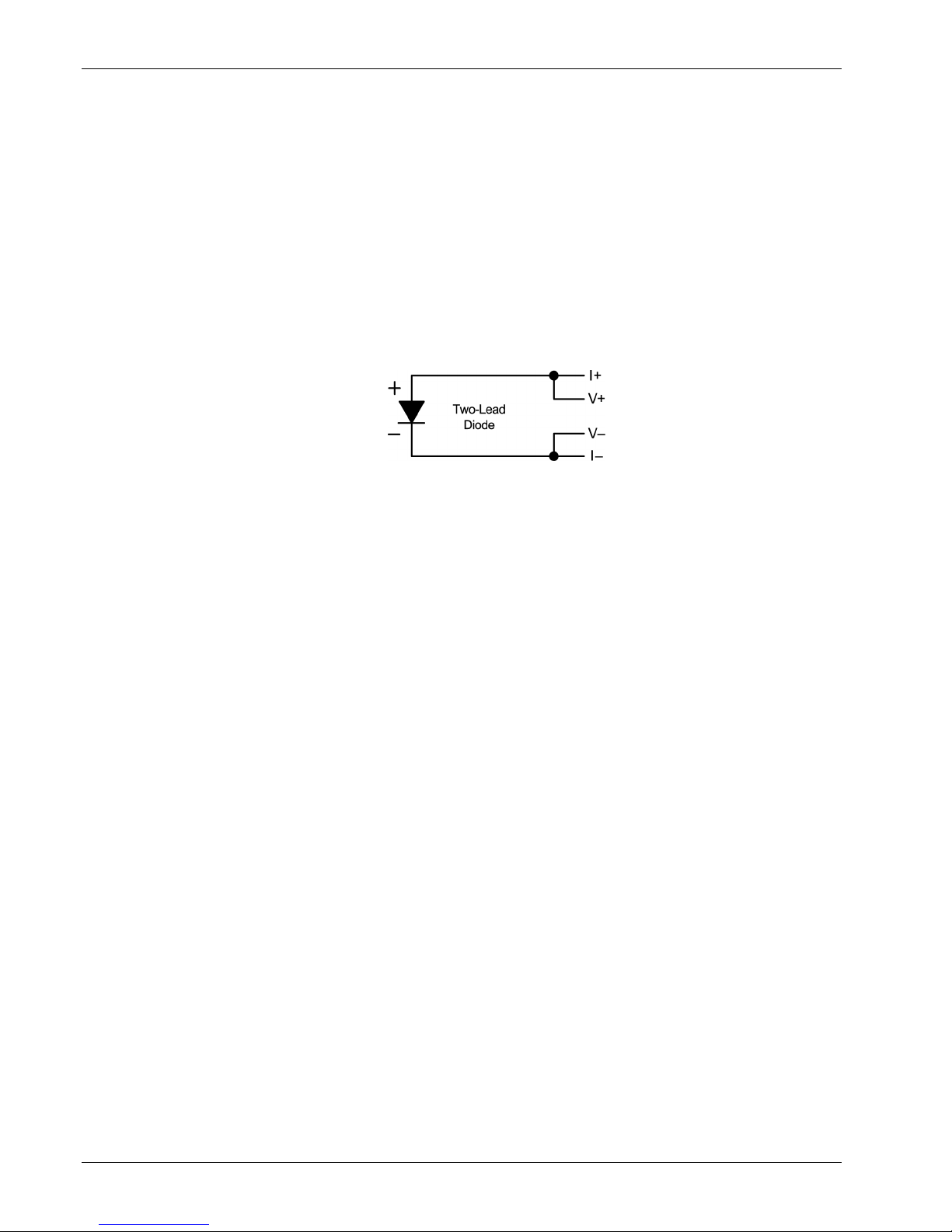
Lake Shore Model 218 Temperature Monitor User’s Manual
Four-Lead Sensor Measurement (Continued)
In a four lead measurement, current leads and voltage leads run separately to the sensor. With
separate leads, there is little current in the voltage leads so their resistance does not enter into the
measurement. Resistance in the current leads will not change the current as long as the voltage
compliance of the current source is not reached. When two lead sensors are used in four lead
measurements, the short leads on the sensor have an insignificant resistance.
NOTE: The Model 218 does not have three-lead measurement capability.
3.3.2.6 Two-Lead Sensor Measurement
Sometimes a crowded cryogenic system forces users to read sensors in a two-lead configuration
because there are not enough feedthroughs or room for lead wires. If this is the case, plus voltage
to plus current and minus voltage to minus current leads are attached at the back of the instrument
or at the vacuum feedthrough.
The error in a resistive measurement is the resistance of the lead wire run with current and voltage
together. If the leads contribute 2 or 3 Ω to a 10 kΩ reading, the error can probably be tolerated.
When measuring voltage for diode sensors the error in voltage can be calculated as the lead
resistance times the current, typically 10 uA. For example: a 10 Ω lead resistance times 10 µA
results in a 0.1 mV error in voltage. Given the sensitivity of a silicon diode at 4.2 K the error in
temperature would be only 3 mK. At 77 K the sensitivity of a silicon diode is lower so the error
would be close to 50 mK. Again, this may not be a problem for every user.
NOTE: The Model 218 does not have three-lead measurement capability.
3.3.2.7 Lowering Measurement Noise
Good instrument hardware setup technique is one of the least expensive ways to reduce
measurement noise. The suggestions fall into two categories: (1) Do not let noise from the outside
enter into the measurement, and (2) Let the instrument isolation and other hardware features work
to their best advantage.
• Use four lead measurement whenever possible.
• Do not connect sensor leads to chassis or earth ground.
• Use twisted shielded cable outside the cooling system.
• Attach the shield pin on the sensor connector to the cable shield.
• Do not attach the cable shield at the other end of the cable, not even to ground.
• Run different inputs and outputs in their own shielded cable.
• Use twisted wire inside the cooling system.
• Use a grounded receptacle for the instrument power cord.
• Consider ground strapping the instrument chassis to other instruments or computers.
3-6 Installation
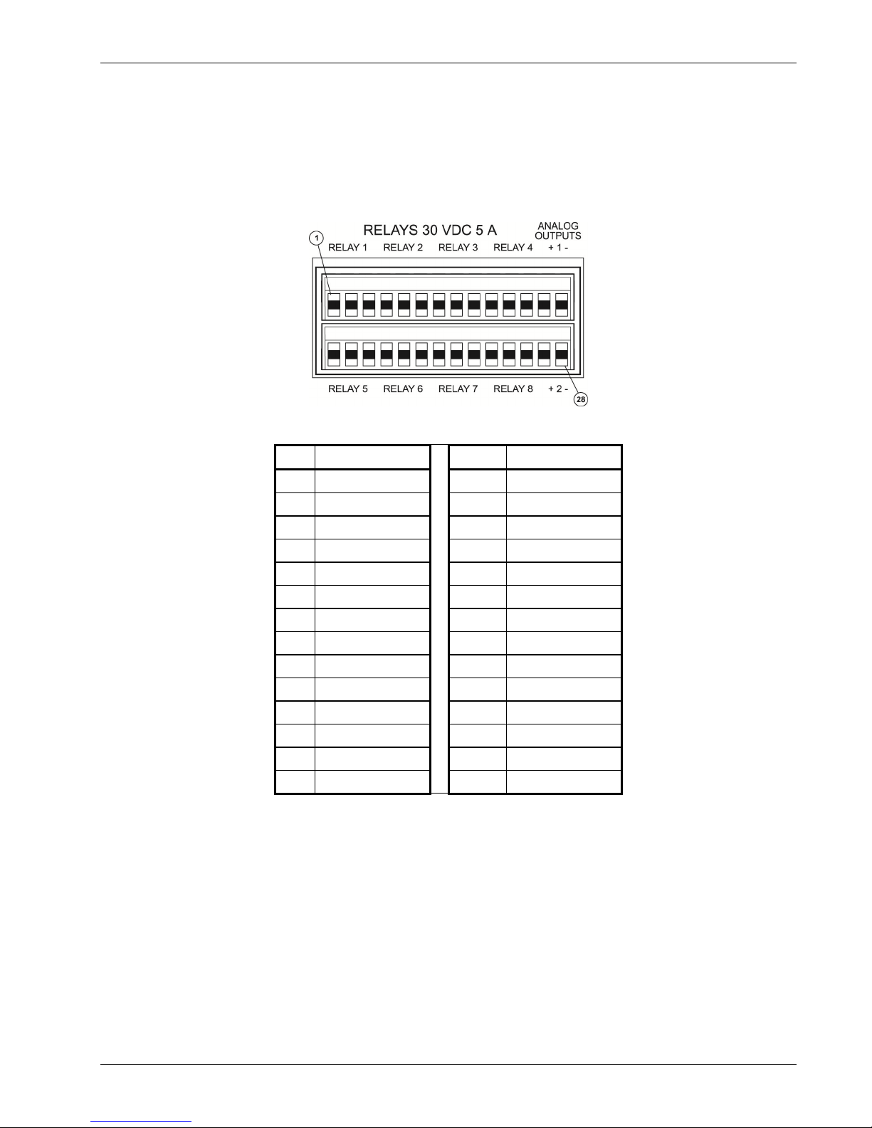
Lake Shore Model 218 Temperature Monitor User’s Manual
3.3.3 Terminal Block (Model 218S only)
The terminal block on the Model 218S rear panel contains signals for analog outputs and alarm
relays. The terminal block connectors are detachable; remove the top or bottom half from the
instrument for convenient wire installation. Use up to 12 AWG stranded copper wire with the
terminals. Smaller wire is suitable for most applications. See Figure 3-4.
F-218-3-4.eps
PIN DESCRIPTION PIN DESCRIPTION
1 Relay 1 NC 15 Relay 5 NC
2 Relay 1 COM 16 Relay 5 COM
3 Relay 1 NO 17 Relay 5 NO
4 Relay 2 NC 18 Relay 6 NC
5 Relay 2 COM 19 Relay 6 COM
6 Relay 2 NO 20 Relay 6 NO
7 Relay 3 NC 21 Relay 7 NC
8 Relay 3 COM 22 Relay 7 COM
9 Relay 3 NO 23 Relay 7 NO
10 Relay 4 NC 24 Relay 8 NC
11 Relay 4 COM 25 Relay 8 COM
12 Relay 4 NO 26 Relay 8 NO
13 Analog 1 Signal 27 Analog 2 Signal
14 Analog 1 Gnd 28 Analog 2 Gnd
Figure 3-4. Terminal Block Connectors
Installation 3-7

Lake Shore Model 218 Temperature Monitor User’s Manual
3.3.3.1 RELAYS (MODEL 218S only)
The Model 218 has eight relays most commonly associated with the alarm feature. If a relay is
inactive (Off), it is in its normal state of open or closed. When the relay is active (On), it is in the
opposite state. The relay contacts are isolated from the instrument ground. Connect to the relay
contacts through the terminal block (refer to Paragraph 3.3.3).
3.3.3.2 Analog Outputs (MODEL 218S only)
Analog Output 1 and 2 on the Model 218S rear panel are voltage outputs that can be used for
monitor applications (Figure 3-4). Their most basic function is a temperature monitor where they put
out a voltage proportional to temperature.
Both analog outputs are variable DC voltage sources that can vary from –10 V to +10 V. The
resolution of the analog output is 1.25 mV or 0.0125% of full scale. They can drive a resistive load
of no less than 1 k. The output is short protected so the instrument is not harmed if resistance is
too small. It is not recommended because the additional load on instrument power supplies causes
noise on internal circuits.
It is not recommended to attach the analog output ground to a ground outside the instrument. The
output should be read by an instrument with an isolated or differential input wherever possible.
Connecting to an external ground can cause noise in the analog output voltage or the sensor input
measurement. If this cannot be avoided, try to keep the chassis of the two instruments at the same
potential with a ground strap. Connect to the analog out contacts through the terminal block (refer
to Paragraph 3.3.3).
3.3.4 Computer Interfaces
Refer to Chapter 6 for details about the IEEE-488 (Model 218S ONLY) and serial computer
interfaces. Refer to also Chapter 5 for details on connecting the serial port to a printer.
3-8 Installation
 Loading...