

Lakeshore 211 User Manual
Rev. 1.6 P/N 119-043 02 March 2011
User’s Manual
Model 211
Temperature Monitor
Serial Numbers 21A0000 and Subsequent
Lake Shore Cryotronics, Inc.
575 McCorkle Boulevard
Westerville, Ohio 43082-8888 USA
E-Mail Addresses:
sales@lakeshore.com
service@lakeshore.com
Visit Our Website:
www.lakeshore.com
Fax: (614) 891-1392
Telephone: (614) 891-2243
Methods and apparatus disclosed and described herein have been developed solely on company funds of Lake Shore
Cryotronics, Inc. No government or other contractual support or relationship whatsoever has existed which in any way affects
or mitigates proprietary rights of Lake Shore Cryotronics, Inc. in these developments. Methods and apparatus disclosed herein
may be subject to U.S. Patents existing or applied for. Lake Shore Cryotronics, Inc. reserves the right to add, improve, modify,
or withdraw functions, design modifications, or products at any time without notice. Lake Shore shall not be liable for errors
contained herein or for incidental or consequential damages in connection with furnishing, performance, or use of this material.

Lake Shore Model 211 User’s Manual
A
LIMITED WARRANTY STATEMENT – WARRANTY PERIOD: ONE (1) YEAR
1. Lake Shore warrants that this Lake Shore product (the ―Product‖) will be free from defects in materials
and workmanship for the Warranty Period specified above (the ―Warranty Period‖). If Lake Shore receives
notice of any such defects during the Warranty Period and the Product is shipped freight prepaid, Lake Shore
will, at its option, either repair or replace the Product if it is so defective without charge to the owner for
parts, service labor or associated customary return shipping cost. Any such replacement for the Product may
be either new or equivalent in performance to new. Replacement or repaired parts will be warranted for only
the unexpired portion of the original warranty or 90 days (whichever is greater).
2. Lake Shore warrants the Product only if it has been sold by an authorized Lake Shore employee, sales
representative, dealer or original equipment manufacturer (OEM).
3. The Product may contain remanufactured parts equivalent to new in performance or may have been
subject to incidental use.
4. The Warranty Period begins on the date of delivery of the Product or later on the date of installation of the
Product if the Product is installed by Lake Shore, provided that if you schedule or delay the Lake Shore
installation for more than 30 days after delivery the Warranty Period begins on the 31st day after delivery.
5. This limited warranty does not apply to defects in the Product resulting from (a) improper or inadequate
maintenance, repair or calibration, (b) fuses, software and non-rechargeable batteries, (c) software,
interfacing, parts or other supplies not furnished by Lake Shore, (d) unauthorized modification or misuse, (e)
operation outside of the published specifications or (f) improper site preparation or maintenance.
6. To the extent allowed by applicable law, the above warranties are exclusive and no other warranty or
condition, whether written or oral, is expressed or implied. Lake shore specifically disclaims any implied
warranties or conditions of merchantability, satisfactory quality and/or fitness for a particular purpose with
respect to the product. Some countries, states or provinces do not allow limitations on an implied warranty,
so the above limitation or exclusion might not apply to you. This warranty gives you specific legal rights and
you might also have other rights that vary from country to country, state to state or province to province.
7. To the extent allowed by applicable law, the remedies in this warranty statement are your sole and
exclusive remedies.
8. Except to the extent prohibited by applicable law, in no event will lake shore or any of its subsidiaries,
affiliates or suppliers be liable for direct, special, incidental, consequential or other damages (including lost
profit, lost data or downtime costs) arising out of the use, inability to use or result of use of the product,
whether based in warranty, contract, tort or other legal theory, and whether or not lake shore has been
advised of the possibility of such damages. Your use of the Product is entirely at your own risk. Some
countries, states and provinces do not allow the exclusion of liability for incidental or consequential
damages, so the above limitation may not apply to you.
9. Except to the extent allowed by applicable law, the terms of this limited warranty statement do not
exclude, restrict or modify, and are in addition to, the mandatory statutory rights applicable to the sale of the
product to you.
CERTIFICATION
Lake Shore certifies that this product has been inspected and tested in accordance with its published
specifications and that this product met its published specifications at the time of shipment. The accuracy
and calibration of this product at the time of shipment are traceable to the United States National Institute of
Standards and Technology (NIST); formerly known as the National Bureau of Standards (NBS), or to a
recognized natural standard.
TRADEMARK ACKNOWLEDGEMENT
Manufacturers and sellers claim many designations as trademarks to distinguish their products. Where those
designations appear in this manual and Lake Shore was aware of a trademark claim, the designations appear
in initial capital letters with a ™ or
®
symbol.
CalCurve™, Cernox™, Duo-Twist™, Quad-Lead™, Quad-Twist™, Rox™, and SoftCal™ are
trademarks of Lake Shore Cryotronics, Inc.
Copyright © 2002, 2005-2011 by Lake Shore Cryotronics, Inc. All rights reserved. No portion of this
manual may be reproduced, stored in a retrieval system, or transmitted, in any form or by any means,
electronic, mechanical, photocopying, recording, or otherwise, without the express written permission of
Lake Shore.

Lake Shore Model 211 User’s Manual
B
ELECTROMAGNETIC COMPATIBILITY ADDENDUM
Electromagnetic Compatibility (EMC) of electronic equipment is a growing concern
worldwide. Emissions of and immunity to electromagnetic interference is now part of most
electronics design and manufacture. To qualify for the CE mark, the Model 211 meets the
generic requirements of the European EMC Directive 89/336/EEC as a Class B product.
The instrument was tested under normal operating conditions with sensor and interface cables
attached. If the installation and operating instructions in the User's Manual are followed there
should be no degradation in EMC performance.
Pay special attention to instrument cabling. Improperly installed cabling may defeat even the
best EMC protection. For the best performance from any precision instrument, follow the
grounding and shielding instructions in the User's Manual. In addition, the installer of the
Model 211 should consider the following:
• Leave no unused or unterminated cables attached to the instrument.
• Make cable runs as short and direct as possible.
• Do not tightly bundle cables that carry different types of signals.
FIRMWARE LIMITATIONS
Lake Shore has worked to ensure that the Model 211 firmware is as free of errors as possible,
and that the results you obtain from the instrument are accurate and reliable. However, as with
any computer-based software, the possibility of errors exists.
In any important research, as when using any laboratory equipment, results should be carefully
examined and rechecked before final conclusions are drawn. Neither Lake Shore nor anyone
else involved in the creation or production of this firmware can pay for loss of time,
inconvenience, loss of use of the product, or property damage caused by this product or its
failure to work, or any other incidental or consequential damages. Use of our product implies
that you understand the Lake Shore license agreement and statement of limited warranty.
FIRMWARE LICENSE AGREEMENT
The firmware in this instrument is protected by United States copyright law and international
treaty provisions. To maintain the warranty, the code contained in the firmware must not be
modified. Any changes made to the code is at the user’s risk. Lake Shore assumes no
responsibility for damage or errors incurred as result of any changes made to the firmware.
Under the terms of this agreement you may only use the Model 211 firmware as physically
installed in the instrument. Archival copies are strictly forbidden. You may not decompile,
disassemble, or reverse engineer the firmware. If you suspect there are problems with the
firmware, return the instrument to Lake Shore for repair under the terms of the Limited
Warranty specified above. Any unauthorized duplication or use of the Model 211 firmware in
whole or in part, in print, or in any other storage and retrieval system is forbidden.

Lake Shore Model 211 User’s Manual
C
This Page Intentionally Left Blank

Lake Shore Model 211 User’s Manual
Table of Contents
i
TABLE OF CONTENTS
Chapter/Paragraph Title Page
1 INTRODUCTION ..................................................................... 1-1
1.0 GENERAL .................................................................................. 1-1
1.1 DESCRIPTION ........................................................................... 1-1
1.2 SPECIFICATIONS ..................................................................... 1-3
1.3 SAFETY SUMMARY ................................................................ 1-8
1.4 SAFETY SYMBOLS .................................................................. 1-9
2 INSTALLATION ...................................................................... 2-1
2.0 GENERAL .................................................................................. 2-1
2.1 INSPECTION AND UNPACKING ............................................ 2-1
2.2 REAR PANEL DEFINITION ..................................................... 2-2
2.3 POWER INPUT CONNECTOR ................................................. 2-2
2.4 EXTERNAL POWER SUPPLY ................................................. 2-3
2.5 CABLE CLAMP ......................................................................... 2-3
2.6 SENSOR INPUT ......................................................................... 2-3
2.6.1 Input/Output Connector ............................................................ 2-4
2.6.2 Sensor Lead Cable .................................................................... 2-4
2.6.3 Shielding Sensor Leads ............................................................ 2-5
2.6.4 Instrument Grounding ............................................................... 2-5
2.6.5 Sensor Polarity .......................................................................... 2-6
2.6.6 4-Lead Sensor Measurement .................................................... 2-6
2.6.7 2-Lead Sensor Measurement .................................................... 2-7
2.6.8 Lowering Measurement Noise .................................................. 2-7
2.7 ANALOG OUTPUT ................................................................... 2-8
2.8 RELAYS ..................................................................................... 2-8
2.9 PANEL MOUNTING ................................................................. 2-9
3 OPERATION ............................................................................. 3-1
3.0 GENERAL .................................................................................. 3-1
3.1 INSTRUMENT POWER ............................................................ 3-1
3.2 DISPLAY DEFINITION ............................................................. 3-1
3.3 LED ANNUNCIATORS and DISPLAY MESSAGES ............... 3-2
3.4 KEYPAD DEFINITION ............................................................. 3-3
3.4.1 Key Descriptions ...................................................................... 3-3
3.4.2 General Keypad Operation ....................................................... 3-3
3.5 INPUT SETUP ............................................................................ 3-4
3.5.1 Input Type ................................................................................ 3-4
3.5.2 Curve Selection ........................................................................ 3-5
3.5.3 Display Units Selection ............................................................ 3-6
3.6 ALARM SETUP and OPERATION ........................................... 3-6
3.7 RELAY SETUP .......................................................................... 3-7

Lake Shore Model 211 User’s Manual
ii
Table of Contents
TABLE OF CONTENTS (continued)
Chapter/Paragraph Title Page
3.8 ANALOG OUTPUT SETUP ...................................................... 3-8
3.9 ANALOG OUTPUT TO TEMPERATURE CONVERSION ..... 3-9
3.10 LOCKING AND UNLOCKING THE KEYPAD ..................... 3-10
3.11 RESETTING THE MODEL 211 TO DEFAULT VALUES ..... 3-10
3.12 CHECKING CODE DATE REVISION .................................... 3-10
3.13 CURVE ENTRY AND STORAGE .......................................... 3-11
3.13.1 Curve Header Parameters ....................................................... 3-11
3.13.2 Curve Breakpoints ................................ ................................ .. 3-12
4 REMOTE OPERATION .......................................................... 4-1
4.0 GENERAL .................................................................................. 4-1
4.1 SERIAL INTERFACE OVERVIEW .......................................... 4-1
4.1.1 Physical Connection ................................................................. 4-1
4.1.2 Hardware Support ..................................................................... 4-2
4.1.3 Character Format ...................................................................... 4-3
4.1.4 Message Strings ........................................................................ 4-3
4.1.5 Message Flow Control .............................................................. 4-4
4.1.6 Serial Interface Basic Program ................................................. 4-5
4.1.6.1 Visual Basic Serial Interface Program Setup ......................... 4-5
4.1.6.2 Program Operation ............................................................... 4-10
4.1.7 Trouble Shooting .................................................................... 4-10
4.2 SERIAL INTERFACE COMMAND SUMMARY ................... 4-11
4.2.1 Interface Commands (In Alphabetical Order) ........................ 4-14
5 SERVICE ................................................................................... 5-1
5.0 GENERAL .................................................................................. 5-1
5.1 CONTACTING LAKE SHORE .................................................. 5-1
5.2 RETURNING PRODUCTS TO LAKE SHORE ........................ 5-2
5.3 ERROR MESSAGES .................................................................. 5-2
5.3.1 Instrument Hardware Errors ..................................................... 5-2
5.3.2 Limit Errors .............................................................................. 5-3
5.4 OPENING THE ENCLOSURE .................................................. 5-3
5.5 CONNECTOR DEFINITIONS ................................................... 5-4
5.5.1 Serial Interface Cable Wiring ................................................... 5-6
5.6 CALIBRATION PROCEDURE ................................................. 5-7
5.6.1 Equipment Required for Calibration ......................................... 5-7
5.6.2 Diode/Resistor Sensor Input Calibration .................................. 5-7
5.6.2.1 Sensor Input Calibration Setup and Serial Communication
Verification ............................................................................ 5-7

Lake Shore Model 211 User’s Manual
Table of Contents
iii
TABLE OF CONTENTS (continued)
Chapter/Paragraph Title Page
5.6.2.2 10 µA Current Source Calibration and 1 mA Current Source
Verification ............................................................................ 5-8
5.6.2.3 Input Gain Calibration ........................................................... 5-8
5.6.3 Analog Output Calibration and Verification........................... 5-10
5.6.3.1 Analog Output Voltage Mode Calibration ........................... 5-10
5.6.3.2 Analog Output Current Mode Calibration ........................... 5-11
5.6.4 Calibration Specific Interface Commands .............................. 5-13
6 OPTIONS AND ACCESSORIES ............................................ 6-1
6.0 GENERAL .................................................................................. 6-1
6.1 MODELS .................................................................................... 6-1
6.2 ACCESSORIES .......................................................................... 6-1
6.3 WIRES ........................................................................................ 6-2
6.4 SENSORS ................................................................................... 6-2
Appendix A CURVE TABLES ....................................................... A-1
A1.0 GENERAL ................................................................................. A-1
Appendix B REGULATORY DECLARATIONS ........................ A-5
B1.0 General ....................................................................................... A-5
B1.1 Model 211 CE Declaration of Conformity ................................. A-6
B1.2 Model 211 RoHS Declaration of Conformity............................. A-7
B1.3 Power Supply CE Declaration, P/N 109-132 ............................. A-8
B1.4 Power Supply RoHS Declaration, P/N 109-132 ......................... A-9
B1.5 CE Declarations for Discontinued Power Supplies .................. A-10
B1.6 RoHS Declarations for Discontinued Power Supplies ............. A-12
Appendix C MENU STRUCTURE .............................................. A-13

Lake Shore Model 211 User’s Manual
iv
Table of Contents
LIST OF ILLUSTRATIONS
Figure No. Title Page
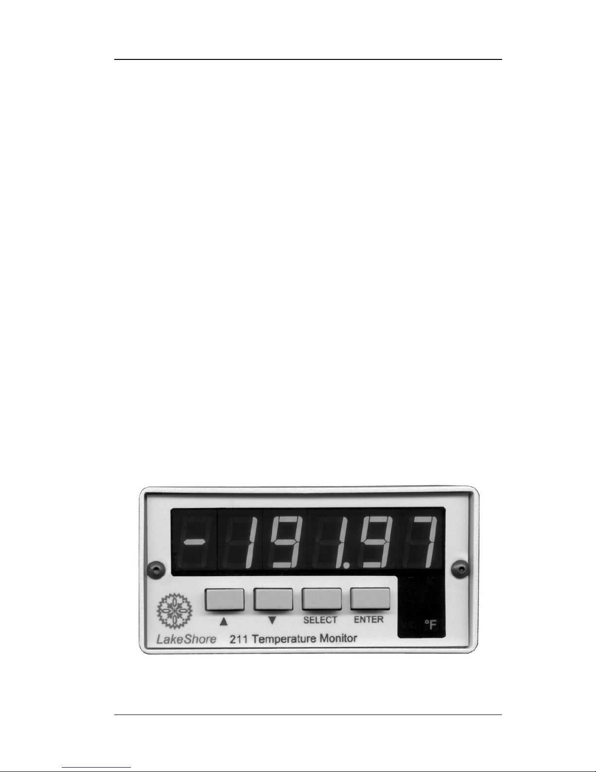
Figure 1-1. Model 211 Front Panel ............................................................ 1-1
Figure 2-1. Model 211 Rear Panel ............................................................. 2-2
Figure 2-2. Power Connector ..................................................................... 2-3
Figure 2-3. Input/Output Connector ........................................................... 2-4
Figure 2-4. Panel Mounting Details ........................................................... 2-9
Figure 2-5. 2111 and 2112 Panel Mount Adapters .................................. 2-10
Figure 3-1. Model 211 Display .................................................................. 3-2
Figure 5-1. Power Connector ..................................................................... 5-4
Figure 5-2. Input/Output Connector ........................................................... 5-4
Figure 5-3. RS-232 (DTE) Connector ........................................................ 5-5
LIST OF TABLES
Table No. Title Page
Table 1-1. Temperature Range of Typical Lake Shore Sensors ................ 1-2
Table 1-2. Sensor Input Performance Chart ............................................... 1-6
Table 3-1. Sensor Input Types ................................................................... 3-4
Table 3-2. Standard Curves ........................................................................ 3-5
Table 3-3. Analog Output Range Scales .................................................... 3-9
Table 3-4. Analog Output Scales in Sensor Units ...................................... 3-9
Table 3-5. Conversion Parameters for Temperature in K .......................... 3-9
Table 3-6. Model 211 Default Values ...................................................... 3-10
Table 3-7. Recommended Curve Parameters ........................................... 3-12
Table 4-1. Serial Interface Specifications .................................................. 4-3
Table 4-2. Serial Interface Program Control Properties ............................. 4-6
Table 4-3. Visual Basic Serial Interface Program ...................................... 4-8
Table 4-4. Interface Commands (Alphabetical Listing) ........................... 4-13
Table 5-1. Calibration Table for Resistive Ranges .................................... 5-9
Table A-1. Lake Shore DT-470 Silicon Diode (Curve 10) ....................... A-1
Table A-2. Lake Shore DT-670 Silicon Diode ......................................... A-2
Table A-3. CTI Curve C Silicon Diode .................................................... A-3
Table A-4. Lake Shore PT-100/-1000 Platinum RTD Curves .................. A-4
Lake Shore Model 211 User’s Manual
Introduction 1-1
CHAPTER 1
INTRODUCTION
1.0 GENERAL
This chapter provides an introduction to the Model 211 Temperature
Monitor. The Model 211 was designed and manufactured in the United
States of America by Lake Shore Cryotronics, Inc. A general description is
provided in Paragraph 1.1, specifications in Paragraph 1.2, safety summary
in Paragraph 1.3, and safety symbols in Paragraph 1.4.
1.1 DESCRIPTION
The Lake Shore single-channel Model 211 Temperature Monitor provides
the accuracy, resolution, and interface features of a benchtop temperature
monitor in an easy to use, easily integrated, compact instrument. With
appropriate sensors, the Model 211 measures temperature from 1.4 to 800 K
and in difficult sensing conditions, including high vacuum and magnetic
fields. Alarms, relays, user-configurable analog voltage or current output,
and a serial interface are standard features on the Model 211. Backed by the
Lake Shore tradition of excellence in cryogenic and precision temperature
measurement for science and industry, the Model 211 is a good choice for
liquefied gas storage/monitoring, cryopump control, cryo-cooler, and
materials science applications, and for applications that require greater
accuracy than thermocouples allow.
211_LED_Front.bmp
Figure 1-1. Model 211 Front Panel

Lake Shore Model 211 User’s Manual
1-2 Introduction
Description (Continued)
The Model 211 Temperature Monitor supports diode temperature sensors
and resistance temperature detectors (RTDs). The Model 211 can be
configured for the type of sensor in use from the instrument front panel.
Four-lead differential measurement and 24-bit analog-to-digital conversion
ensure high accuracy and 5-digit measurement resolution. Temperature data
can be read up to seven times per second over computer interface; the
display is updated twice each second.
The Model 211 converts voltage or resistance to temperature units based on
temperature response curve data for the sensor in use. Standard temperature
response curves for silicon diodes and platinum RTDs are included in
instrument firmware. The Model 211 also provides non-volatile memory for
one 200-point temperature response curve, which can be entered via the
serial interface. Measurements are available in temperature units K, °C, °F,
or sensor units V or .
With an RS-232C serial interface and other interface features, the Model
211 is valuable as a stand-alone monitor and is easily integrated into other
systems. Setup and every instrument function can be performed via serial
interface or the front panel of the Model 211. High and low alarms can be
used in latching mode for error limit detection and in non-latching mode in
conjunction with relays to perform simple on-off control functions. The
analog output can be configured for either 0 to 10 V or 4 to 20 mA output.
Table 1-1. Temperature Range of Typical Lake Shore Sensors*
Diodes
Model
Useful Range
Silicon Diodes
DT-670
1.4 – 500 K
GaAlAs Diode
TG-120
1.4 – 475 K
Positive Temperature Coefficient (PTC) RTDs
100 Platinum RTD
PT-100, 250 full scale
30 – 675 K
100 Platinum RTD
PT-100, 500 full scale
30 – 800 K
Rhodium-Iron RTD
RF-800-4
1.4 – 400 K
Negative Temperature Coefficient (NTC)† RTDs
Germanium RTD
GR-200A-1000
2 – 100 K
Germanium RTD
GR-200A-250
1.2 – 40 K
Carbon-Glass RTD
CGR-1-500
3 – 325 K
Cernox™ RTD
CX-1050 AA or SD
3.5 – 325 K
Cernox™ RTD
CX-1030 AA or SD
2 – 325 K
High-Temperature Cernox™ RTD
CX-1030-SD-HT
2 – 420 K
Rox™ Ruthenium Oxide RTD
RX-102A
2 – 40 K
Rox™ Ruthenium Oxide RTD
RX-202A
3 – 40 K
* Sensors sold separately.
†
Single excitation current may limit the low temperature range of NTC resistors.

Lake Shore Model 211 User’s Manual
Introduction 1-3
1.2 SPECIFICATIONS
Thermometry
Number of Inputs: 1
Measurement Type: 4-lead differential
Excitation: Constant current, 10 µA or 1 mA
Isolation: Measurement is not isolated from chassis ground
A/D Resolution: 24-bit
Input Accuracy: Sensor dependent; refer to Table 1-2
Measurement Resolution: Sensor dependent; refer to Table 1-2
Maximum Update Rate: 7 rdg/s
Supported Sensors: Diodes: Silicon, GaAlAs;
RTDs: 100 Platinum, 1000 Platinum, Cernox™, Carbon-Glass, Rox™
Standard Curves: DT-470, DT-670, CTI Curve C, PT-100, PT-1000
User Curve: One 200-point CalCurve™ or user curve in non-volatile memory
Settings: Sensor Type, Sensor Curve
Input Connector: DB-25
Front Panel
Display Type: 5-digit LED
Display Units: K, °C, °F, V,
Display Update Rate: 2 rdg/s
Temperature Display Resolution: 0.001° between 0 – 99.999°,
0.01° between 100 – 999.99°, 0.1° above 1000°
Sensor Units Display Resolution: Sensor dependent to 5 digits
Display Annunciators: K, °C, °F, V/
Keys: Select, Enter, s (Up Arrow), t (Down Arrow)
Front Panel Features: Display Units, Display Brightness,
Keypad Lockout, Instrument Reset
Interface
Serial Interface:
Format: RS-232C
Baud Rate: 9600 baud
Reading Rate: To 7 rdg/s
Special Features: User Curve Entry, LabView™ Driver
Connector: DE-9
Alarms:
Number: 2, High and Low
Settings: High Setpoint, Low Setpoint, Dead band,
Latching or Non-Latching, Alarm On/Off
Actuators: Display message, relays
Lake Shore Model 211 User’s Manual
1-4 Introduction
Interface (Continued)
Relays:
Number: 2
Contacts: Normally Open (NO), Normally Closed (NC), and Common (C)
Contact Rating: 30 VDC at 1 A
Settings: manually off, manually on, follows alarms
Connector: DB-25 (shares input connector)
Analog Output:
Isolation: Output is not isolated from chassis ground
Update Rate: 7 rdg/s
Voltage
Current
Range:
0 – 10 V
4 – 20 mA
Resolution:
0.15 mV
0.3 µA
Accuracy:
±1.25 mV
±5.0 µA
Minimum Load Resistance:
500 (short-
circuit protected)
NA
Compliance Voltage:
NA
10 V
Load Regulation
NA
±0.02% rdg
0 to 500
Scales:
Temperature
Sensor Units (Fixed by type)
0 – 20 K
0 – 100 K
0 – 200 K
0 – 325 K
0 – 475 K
0 – 1000 K
Diodes: 1 V = 1V
100 Platinum: 1 V = 100
1000 Platinum: 1 V = 1000
NTC Resistor: 1 V = 1000
Settings: Voltage or current, scale
Connector: DB-25 (shares input connector)
General
Ambient Temperature Range: 15 – 35 °C (59 – 95 °F) at rated accuracy,
10 – 40 °C (50 – 104 °F) at reduced accuracy
Power Requirement: Regulated +5 VDC at 400 mA, Barrel Plug 5.5mm OD x
2.1mm ID x 9.9mm L
Size: 96 mm W × 48 mm H × 166 mm D (3.8 × 1.9 × 6.5 in)
Mounting: Panel mount into 91 mm W × 44 mm H (3.6 × 1.7 in) cutout
Weight: 0.45 kg (1 lb)
Approval: CE mark, RoHS compliant

Lake Shore Model 211 User’s Manual
Introduction 1-5
Power Supply (109-132)
Power requirements: 100-240 VAC, 50 or 60 Hz, 0.3 A max
Output: +5 V at 1.2 A
Size: 40.5 mm W × 30.0 mm H × 64 mm D (1.6 in × 1.2 in × 2.5 in)
Weight: 0.15 kg (0.33 lb)
Ordering Information
Part Number Description
211S Model 211 temperature monitor, single channel
211N Model 211 with no power supply
Accessories included with the Model 211 Temperature Monitor
109-132 100-240 V, 6 W power supply (universal input,
interchangeable input plugs)
G-106-253 Sensor input mating connector (DB-25)
G-106-264 Shell for sensor input mating connector
G-110-110 Rubber feet
0-204 Cable clamp
— Calibration certificate
MAN-211 User’s manual
Options and Accessories
2111 Single ¼-DIN panel mount adapter (see Figure 2-5)
2112 Dual ¼-DIN panel mount adapter (see Figure 2-5)
8000 CalCurve™ , CD-ROM (included with calibrated sensor)
8001-211 CalCurve™, factory installed
CAL-211-CERT Instrument recalibration with certificate
CAL-211 DATA Instrument recalibration with certificate and data

Lake Shore Model 211 User’s Manual
1-6 Introduction
Table 1-2. Sensor Input Performance Chart
Sensor Type
Silicon Diode
GaAlAs Diode
Temperature Coefficient
Negative
Negative
Sensor Units
volts (V)
volts (V)
Input Range
0 – 2.5 V
0 – 7.5 V
Sensor Excitation (Constant Current)
10 µA ±0.01%
10 µA ±0.01%
Display Resolution (Sensor Units)
100 µV
100 µV
Example Lake Shore Sensor
DT-670-SD
with 1.4H calibration
TG-120SD
with 1.4H calibration
Temperature Range
1.4 – 475 K
1.4 – 475 K
Standard Sensor Curve
DT-670
Requires calibration
Typical Sensor Sensitivity
–31.6 mV/K at 4.2 K
–1.73 mV/K at 77 K
–2.3 mV/K at 300 K
–2.12 mV/K at 500 K
–180 mV/K at 10 K
–1.25 mV/K at 77 K
–2.75 mV/K at 300 K
–2.75 mV/K at 475 K
Measurement Resolution:
Sensor Units
Temperature Equivalence
20 µV
0.6 mK at 4.2 K
11.6 mK at 77 K
8.7 mK at 300 K
9.4 mK at 500 K
20 µV
1 mK at 10 K
16 mK at 77 K
10 mK at 300 K
10 mK at 475 K
Electronic Accuracy:
Sensor Units
Temperature Equivalence
±160 µV ±0.01% rdg
±10 mK at 4.2 K
±152 mK at 77 K
±94 mK at 300 K
±80 mK at 500 K
±160 µV ±0.02% rdg
±6 mK at 10 K
±300 mK at 77 K
±150 mK at 300 K
±110 mK at 475 K
Temperature Coefficient
±10 µV ±5 PPM
of reading per °C
±20 µV ±5 PPM
of reading per °C
Temperature Accuracy
including electronic accuracy,
CalCurve™ and calibrated
sensor
±31 mK at 4.2 K
±267 mK at 77 K
±154 mK at 300 K
±140 mK at 500 K
±21 mK at 10 K
±390 mK at 77 K
±140 mK at 300 K
±210 mK at 475 K
Magnetic Field Use
Recommended for
T > 60 K & B < 3 T
Recommended for
T > 4.2 K & B < 5 T

Lake Shore Model 211 User’s Manual
Introduction 1-7
Table 1-2. Sensor Input Performance Chart (Continued)
100 Platinum RTD
500 Full Scale
1000 Platinum RTD
Cernox™ RTD
Positive
Positive
Negative
ohms ()
ohms ()
ohms ()
0 – 500
0 – 5000
0 – 7500
1 mA ±0.3%
1 mA ±0.3%
10 µA ±0.01%
10 m
100 m
100 m
PT-103 with
14J calibration
PT-1001*
with 1.4J calibration
CX-1050-SD
with 4L calibration
30 – 800 K
30 – 800 K
3.5 – 400 K
DIN 43760
Scaled from DIN 43670
Requires calibration
0.19 /K at 30 K
0.42 /K at 77 K
0.39 /K at 300 K
0.35 /K at 675 K
0.33 /K at 800 K
1.9 /K at 30 K
4.2 /K at 77 K
3.9 /K at 300 K
3.3 /K at 800 K
–770 /K at 4.2 K
–1.5 /K at 77 K
–0.1 /K at 300 K
2 m
10.6 mK at 30 K
10 mK at 77 K
10 mK at 300 K
10 mK at 675 K
10 mK at 800 K
20 m
10.6 mK at 30 K
10 mK at 77 K
10 mK at 300 K
10 mK at 800 K
50 m
1 mK at 4.2 K
33.3 mK at 77 K
500 mK at 300 K
±0.004 ±0.02% rdg
±25 mK at 30 K
±18 mK at 77 K
±70 mK at 300 K
±162 mK at 675 K
±187 mK at 800 K
±0.06 ±0.04% rdg
±40 mK at 30 K
±33 mK at 77 K
±135 mK at 300 K
±370 mK at 800 K
±0.1 ±0.04% rdg
±1 mK at 4.2 K
±88 mK at 77 K
±1.144 K at 300 K
±0.2 m ±5 PPM
of reading per °C
±2.0 m ±5 PPM
of reading per °C
±20 m ±15 PPM
of reading per °C
±45 mK at 30 K
±38 mK at 77 K
±105 mK at 300 K
±262 mK at 675 K
±287 mK at 800 K
±60 mK at 30 K
±53 mK at 77 K
±170 mK at 300 K
±470 mK at 800 K
±9 mK at 4.2 K†
±138 mK at 77 K†
±1.284 K at 300 K†
Recommended for
T > 40 K & B < 2.5 T
Recommended for
T > 40 K & B < 2.5 T
Recommended for
T > 2 K & B < 19 T
* No longer available from Lake Shore.
† Specified accuracy includes no effects of thermal EMF voltages.
An error of 3 m results from each 1 µV of thermal EMF voltage.
In well-designed systems, thermal EMF voltage should be <10 µV.

Lake Shore Model 211 User’s Manual
1-8 Introduction
1.3 SAFETY SUMMARY
Observe these general safety precautions during all phases of instrument
operation, service, and repair. Failure to comply with these precautions or
with specific warnings elsewhere in this manual violates safety standards of
design, manufacture, and intended instrument use. Lake Shore Cryotronics,
Inc. assumes no liability for Customer failure to comply with these
requirements.
The Model 211 protects the operator and surrounding area from electric
shock or burn, mechanical hazards, excessive temperature, and spread of
fire from the instrument.
The Model 211 is designed for indoor use only. Improper use of the
instrument may pose a hazard to the operator and surrounding area.
The power supply included with the Model 211 meets or exceeds the
European Union Standard, EN-60950.
Do Not Operate in an Explosive Atmosphere
Do not operate the instrument in the presence of flammable gases or fumes.
Operation of any electrical instrument in such an environment constitutes a
definite safety hazard.
Keep Away from Live Circuits
Operating personnel must not remove instrument covers. Refer component
replacement and internal adjustments to qualified maintenance personnel.
Do not replace components with power cable connected. To avoid injuries,
always disconnect power and discharge circuits before touching them.
Do Not Substitute Parts or Modify Instrument
Do not install substitute parts or perform any unauthorized modification to
the instrument. Return the instrument to an authorized Lake Shore
Cryotronics representative for service and repair to ensure that safety
features are maintained.
Cleaning
Do not submerge instrument. Clean only with a damp cloth and mild
detergent — exterior only.
Lake Shore Model 211 User’s Manual
Introduction 1-9
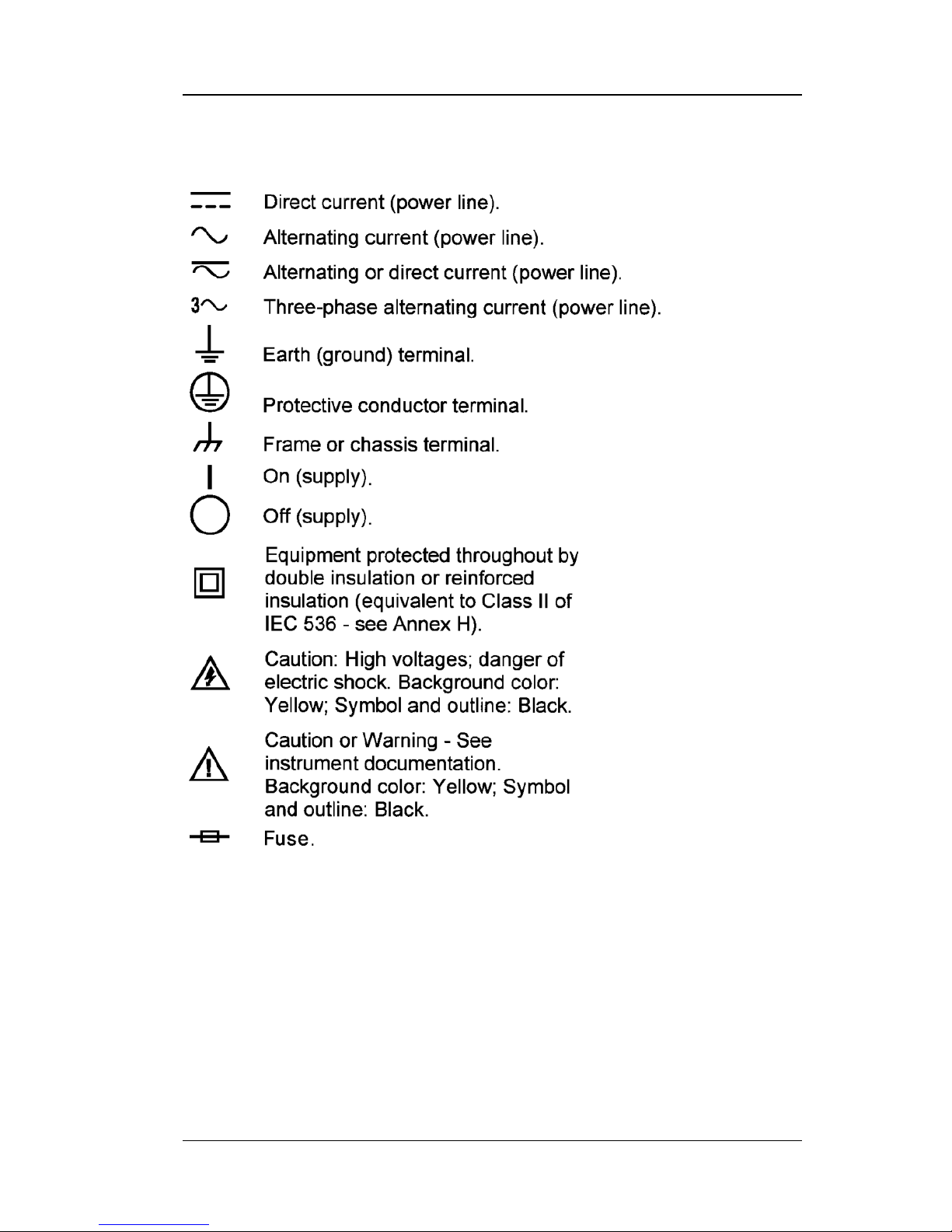
1.4 SAFETY SYMBOLS

Lake Shore Model 211 User’s Manual
1-10 Introduction
This Page Intentionally Left Blank

Lake Shore Model 211 User’s Manual
Installation 2-1
CHAPTER 2
INSTALLATION
2.0 GENERAL
This chapter provides general installation instructions for the Model 211
Temperature Monitor. To ensure the best possible performance and to
maintain operator safety, please read the entire chapter before installing and
operating the instrument. Refer to Chapter 3 for operating instructions.
Refer to Chapter 4 for computer interface installation and operation.
2.1 INSPECTION AND UNPACKING
Inspect shipping containers for external damage before opening. Photograph
any container that has significant damage before opening it. If there is
visible damage to the contents of the container, contact the shipping
company and Lake Shore immediately, preferably within 5 days of receipt
of goods. Keep all damaged shipping materials and contents until instructed
to either return or discard them.
Open the shipping container and keep the container and shipping materials
until all contents have been accounted for. Check off each item on the
packing list as it is unpacked. Instruments may be shipped as several parts.
The items included with the Model 211 are listed as follows.
Items Included with Model 211 Temperature Monitor:
Model 211 Instrument
Model 211 User’s Manual
Input/Output Mating Connector and Shell
Panel Mount Hardware Installed at Factory
Universal Input Power Supply (interchangeable plug style)
Cable Clamp
Rubber Feet
Contact Lake Shore immediately if there is a shortage of parts or
accessories. Lake Shore is not responsible for any missing items if not
notified within 60 days of shipment.
Inspect all items for both visible and hidden damage that occurred during
shipment. If damage is found, contact Lake Shore immediately for
instructions on how to file a proper insurance claim. Lake Shore products
are insured against damage during shipment but a timely claim must be
filed before Lake Shore will take further action. Procedures vary slightly
with shipping companies. Keep all shipping materials and damaged
contents until instructed to either return or discard them.
Lake Shore Model 211 User’s Manual
2-2 Installation
Inspection and Unpacking (Continued)
If the instrument must be returned for recalibration, replacement or repair, a
returned goods authorization (RGA) number must be obtained from a
factory representative before it is returned. The Lake Shore RGA procedure
is given in Paragraph 5.2.
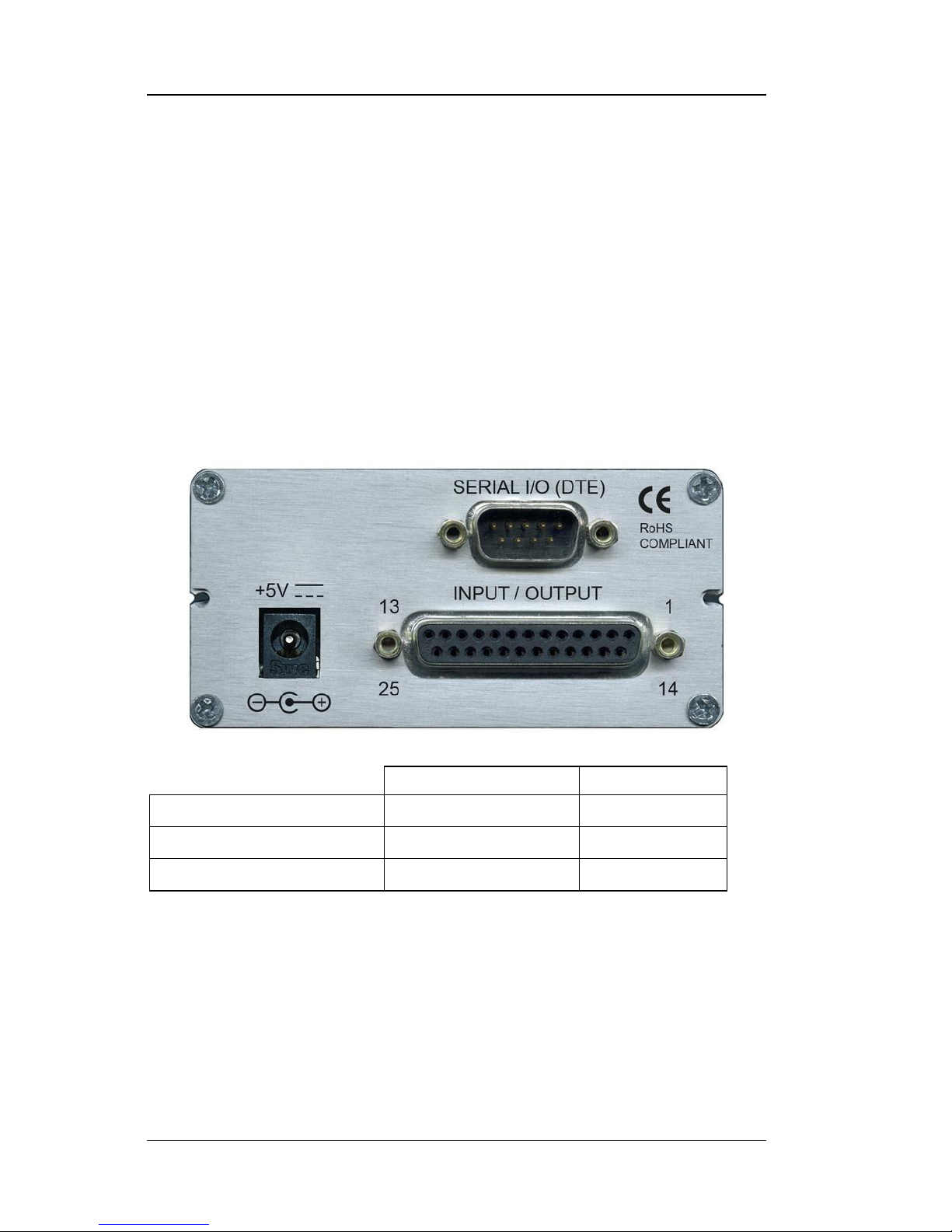
2.2 REAR PANEL DEFINITION
This paragraph describes the connectors on the rear panel of the Model 211.
See Figure 2-1. Readers are referred to paragraphs that contain installation
instructions and connector pin-outs for each feature. A summary of
connector pin-outs is provided in Paragraph 5.5.
CAUTION: Only make rear panel connections with power supply
disconnected.
211_Rear.jpg
Description
Details
POWER 5V DC
Paragraph 2.3
Figure 5-1
SERIAL I/O (DTE) DE-9
Paragraph 4.1.1
Figure 5-3
INPUT/OUTPUT DB-25
Paragraph 2.6.1
Figure 5-2
Figure 2-1. Model 211 Rear Panel
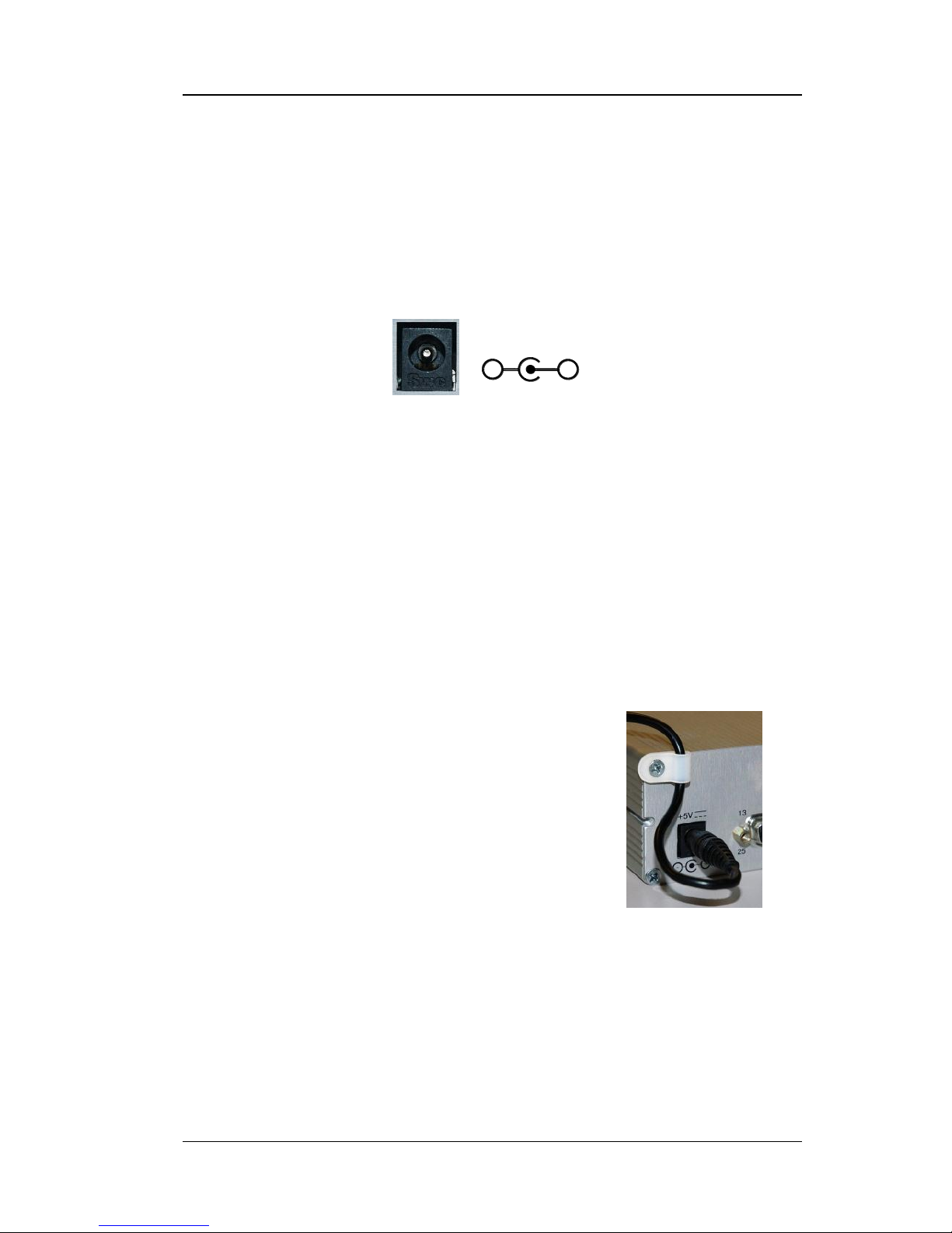
2.3 POWER INPUT CONNECTOR
Power is supplied to the Model 211 through a coaxial connector located on
the rear panel of the instrument. There is no power switch on the
instrument, so it is off when not plugged in, or on when plugged in. Make
sensor connections before applying power to the instrument.
Lake Shore Model 211 User’s Manual
Installation 2-3
Power Input Connector (Continued)
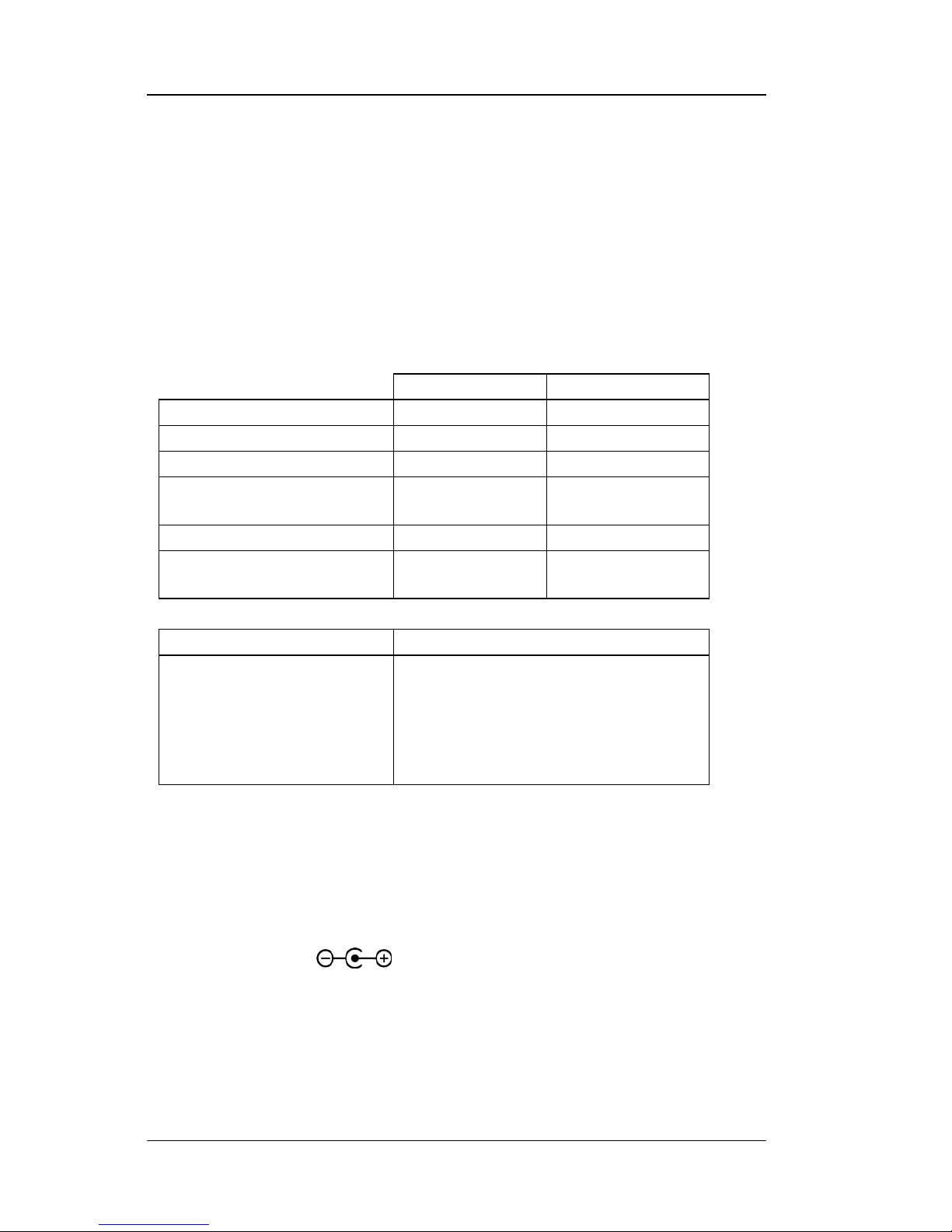
The instrument requires +5 VDC at 400 mA. The coaxial connector accepts
a barrel plug 5.5mm OD x 2.1mm ID x 9.9mm L. Refer to Figure 2-2 for
polarity.
WARNING: To prevent electrical fire or shock hazards, do not expose this
instrument, or its power supply, to rain or excess moisture.
+
–
Figure 2-2. Power Connector
2.4 EXTERNAL POWER SUPPLY
The Model 211 comes with the universal input power supply, Lake Shore
P/N 109-132. It can accept input voltages from 100 to 240 VAC (±10%),
50 to 60 Hz. For input power, it has interchangeable plugs to accommodate
power receptacles in different countries. It has a barrel plug for the output.
It can output +5 V at 0 to 1.2 A. The power supply is CE certified and meets
or exceeds the following safety standards: UL 60950-1 and EN 60950. To
change plugs, press the pad on the side of the plug, pull off the old plug and
snap in the new plug.
2.5 CABLE CLAMP
To avoid inadvertent disconnection from the power
supply, Lake Shore supplies a cable clamp that the
user may attach to the cord and the instrument
chassis. It is a part of the accessories kit supplied
with the unit. To install the clamp, remove the
screw at the top left rear of the unit, position the
cord and clamp as shown in the photo and reinstall
the screw.
2.6 SENSOR INPUT
This paragraph details how to connect diode and resistor sensors to the
Model 211 input. Refer to Paragraph 3.5 to configure the input. Sensor
installation instructions are provided in the Lake Shore Temperature
Measurement and Control Catalog.
Lake Shore Model 211 User’s Manual
2-4 Installation
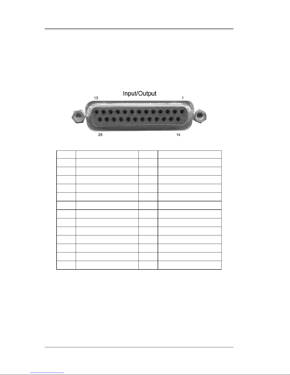
2.6.1 Input/Output Connector
Sensors are connected to the Model 211 through the Input/Output connector
on the rear panel of the instrument. The Input/Output connector is also used
for the analog output and relay connections. Refer to Figure 2-3 for pin
descriptions.
P-211-2-3.bmp
Pin
Description
Pin
Description
1
No Connection
— — 2
Shield
14
Shield
3
I+
15
I–
4
V+
16
V– 5 Shield
17
Shield
6
Analog Output Signal
18
Analog Output Ground
7
No Connection
19
No Connection
8
Low Alarm COM
20
Low Alarm NO
9
Low Alarm NC
21
No Connection
10
No Connection
22
No Connection
11
High Alarm COM
23
High Alarm NO
12
High Alarm NC
24
No Connection
13
No Connection
25
No Connection
Figure 2-3. Input/Output Connector
2.6.2 Sensor Lead Cable
The sensor lead cable used outside the cooling system can be much
different from what is used inside. Between the instrument and vacuum
shroud, heat leak is not a problem, but errors from noise pick up need to be
minimized. Larger conductor, 22 to 28 AWG stranded copper wire is
recommended because it has low resistance yet remains flexible when
several wires are bundled in a cable.

Lake Shore Model 211 User’s Manual
Installation 2-5
Sensor Lead Cable (Continued)
The arrangement of wires in a cable is also important. For best results, twist
voltage leads, V+ and V– together and twist current leads I+ and I–
together. Cover the twisted pairs of voltage and current leads with a braided
or foil shield connected to the shield pin of the instrument. This type of
cable is available through local electronics suppliers. Instrument
specifications are given assuming 10 feet of sensor cable. Longer cables,
100 feet or more, can be used but environmental conditions may degrade
accuracy and noise specifications.
2.6.3 Shielding Sensor Leads
Shielding the sensor lead cable is important to keep external noise from
entering the measurement. The sensor lead cable should be shielded
whenever possible. In many systems, it is impractical to shield the sensor
leads inside the cryostat. In theses cases, the cable shield should still be
used on the room temperature sensor leads up to the cryostat.
A shield is most effective when it is near the measurement potential, so the
Model 211 offers a shield pin on the Input/Output Connector that stays
close to the measurement. The shield pin is tied to chassis ground and
should be used as the connection point for the sensor cable shield.
Depending on how the instrument is grounded, the shield may or may not
need to be terminated at the opposite end. See Paragraph 2.6.4 below on
instrument grounding.
2.6.4 Instrument Grounding
The Model 211 does not provide isolation between measurement circuits
and chassis ground. The measurement leads have a finite impedance to
chassis ground and should not be tied to ground outside the instrument or an
error in reading may result. The Model 211 has the best noise performance
when the chassis is tied to earth ground. This connection should be made at
only one point so as to avoid ground loops.
If the sensor leads are shielded, the cable shield should be tied to the shield
pins on the Input/Output connector but should not be terminated at the other
end.
The standard power supply (109-132) does not connect the common pins to
earth ground. The connection should be made externally. If the sensor leads
are shielded, one end of the cable shield can be tied to the cryostat ground
while the other end is tied to the shield pins on the Input/Output connector.
If the sensor leads are not shielded, the instrument chassis should be
strapped to earth ground.
Lake Shore Model 211 User’s Manual
2-6 Installation
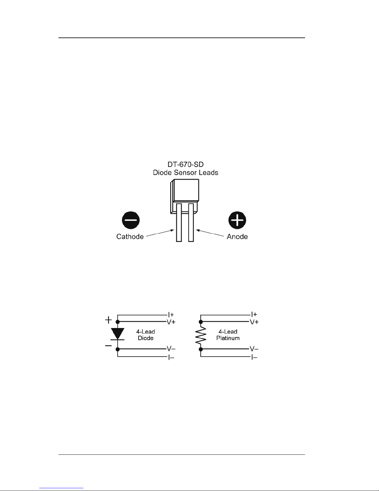
2.6.5 Sensor Polarity
Lake Shore sensors ship with instructions that indicate which sensor leads
are which. It is important to follow these instructions for plus and minus
leads (polarity) as well as voltage and current when applicable. Diode
sensors do not operate in the wrong polarity. They look like an open circuit
to the instrument. 2-lead resistors can operate with any lead arrangement
and the sensor instructions may not specify polarity. 4-lead resistors may
depend more on lead arrangement. Follow any specified lead assignment for
four lead resistors. Mixing leads could give a reading that appears correct,
but is not the most accurate.
2.6.6 4-Lead Sensor Measurement
All sensors, including both 2-lead and 4-lead can be measured with a 4-lead
technique. 4-lead measurement eliminates the effect of lead resistance on
the measurement. If it is not taken out, lead resistance is a direct error when
measuring a sensor.
In a 4-lead measurement, current leads and voltage leads run separately to
the sensor. With separate leads, there is little current in the voltage leads so
their resistance does not enter into the measurement. Resistance in the
current leads will not change the current as long as the voltage compliance
of the current source is not reached. When 2-lead sensors are used in 4-lead
measurements, the short leads on the sensor have an insignificant resistance.
Lake Shore Model 211 User’s Manual
Installation 2-7
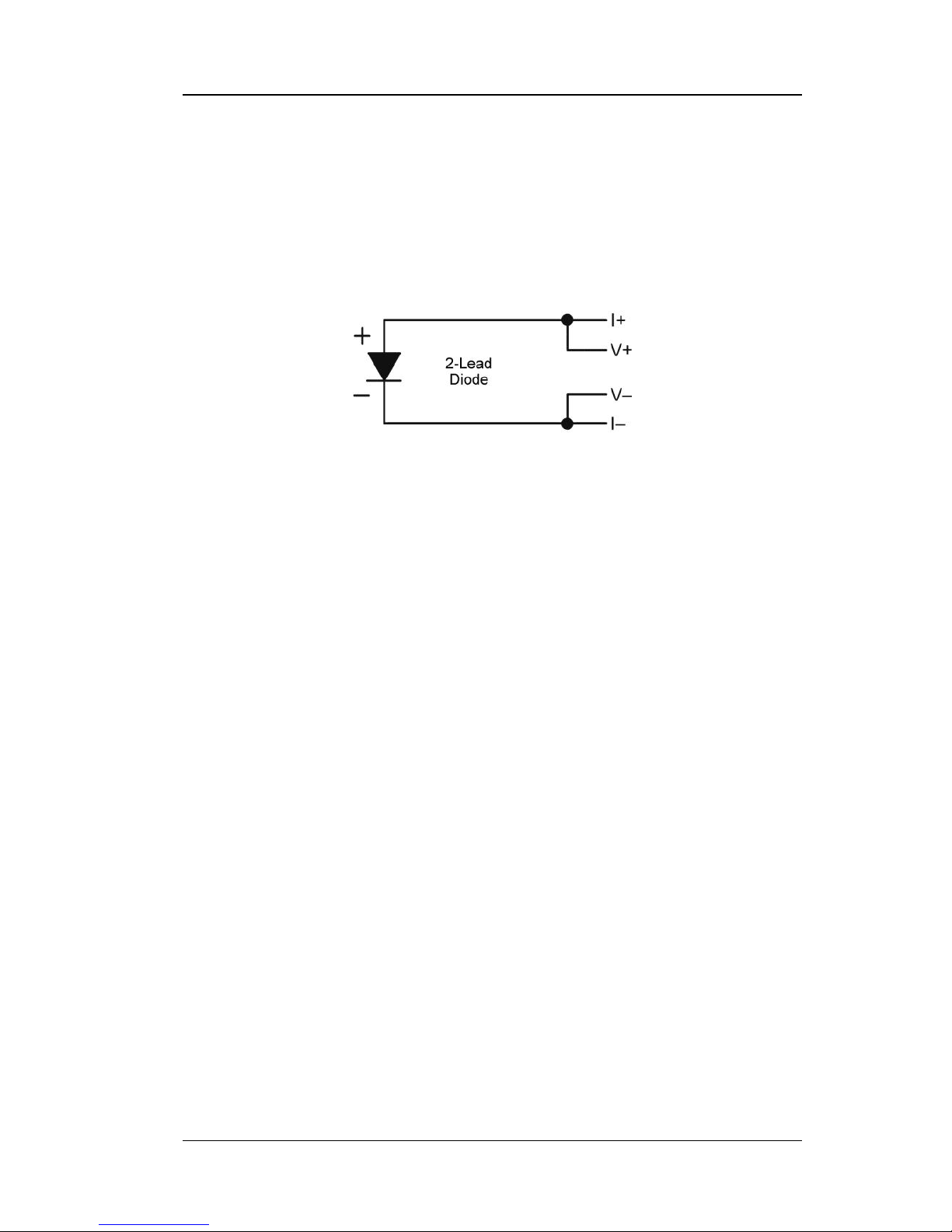
2.6.7 2-Lead Sensor Measurement
Sometimes a crowded cryogenic system forces users to read sensors in a
2-lead configuration because there are not enough feedthroughs or room for
lead wires. If this is the case, plus voltage to plus current and minus voltage
to minus current leads are attached at the back of the instrument or at the
vacuum feedthrough.
The error in a resistive measurement is the resistance of the lead wire run
with current and voltage together. If the leads contribute 2 or 3 to a 5 k
reading, the error can probably be tolerated. When measuring voltage for
diode sensors the error in voltage can be calculated as the lead resistance
times the current, typically 10 µA. For example: a 10 lead resistance
times 10 µA results in a 0.1 mV error in voltage. Given the sensitivity of a
silicon diode at 4.2 K the error in temperature would be only 3 mK. At 77 K
the sensitivity of a silicon diode is lower so the error would be close to
50 mK. Again, this may not be a problem for every user.
2.6.8 Lowering Measurement Noise
Good instrument hardware setup technique is one of the least expensive
ways to reduce measurement noise. The suggestions fall into two
categories: (1) Do not let noise from the outside enter into the measurement,
and (2) Let the instrument hardware features work to their best advantage.
• Use 4-lead measurement whenever possible.
• Do not connect sensor leads to chassis or earth ground.
• Use twisted shielded cable outside the cooling system.
• Attach the shield pin on the sensor connector to the cable shield.
• Do not attach the cable shield at the other end of the cable, not even to
ground without taking precautions to prevent ground loops.
• Run different inputs and outputs in their own shielded cable.
• Use twisted wire inside the cooling system.
• Consider ground strapping the instrument chassis to other instruments or
computers.

Lake Shore Model 211 User’s Manual
2-8 Installation
2.7 ANALOG OUTPUT
The Analog Output available on the rear panel of the Model 211 can be
configured as either a voltage or current output that can be used for monitor
and control applications. Its most basic function is a temperature monitor
where it puts out a voltage or current that is proportional to temperature.
Refer to Paragraph 3.8 to configure the analog output.
In voltage mode the analog output can vary from 0 – 10 V with a resolution
of 0.15 mV or 0.0015% of full scale. The output can drive a resistive load
of no less than 500 . The output is short-circuit protected so the instrument
is not harmed if the load resistance is too small. However, this practice is
not recommended as the additional load on the instrument power supply
causes noise on internal circuits.
In current mode, the analog output can vary from 4 to 20 mA with a
resolution of 0.3 µA or 0.0015% of full scale. The output is limited by a
10 V compliance voltage so the largest resistive load that the output can
drive in current mode is 500 .
The output for the analog output is available from Pins 6 and 18 of the
Input/Output connector. See Figure 2-3. The terminal marked analog output
signal is the output voltage terminal; the terminal marked analog output
ground is the ground and is attached to chassis ground inside the instrument.
It is not recommended to attach the analog output ground to a ground
outside the instrument. The output should be read by an instrument with an
isolated or differential input wherever possible. Connecting to an external
ground can cause noise in the analog output voltage or the sensor input
measurement. If this cannot be avoided, try to keep the chassis of the two
instruments at the same potential with a ground strap.
2.8 RELAYS
The Model 211 has two relays, labeled high and low. The relays are most
commonly associated with the alarm feature. The relays can also be placed
in manual mode and controlled directly by the user from the front panel or
over the computer interface. Refer to Paragraph 3.7 and the RELAY
command in Chapter 4.
Normally Open (NO), Normally Closed (NC), and Common (COM)
contacts are available for each relay. All contacts (including common) are
isolated from the measurement and chassis grounds of the instrument. If a
relay is inactive (Off), it will be in its normal state of open or closed. When
the relay is active (On), it will be in the opposite state. Relay connections
are available on the Input/Output connector. See Figure 2-3.
Lake Shore Model 211 User’s Manual
Installation 2-9
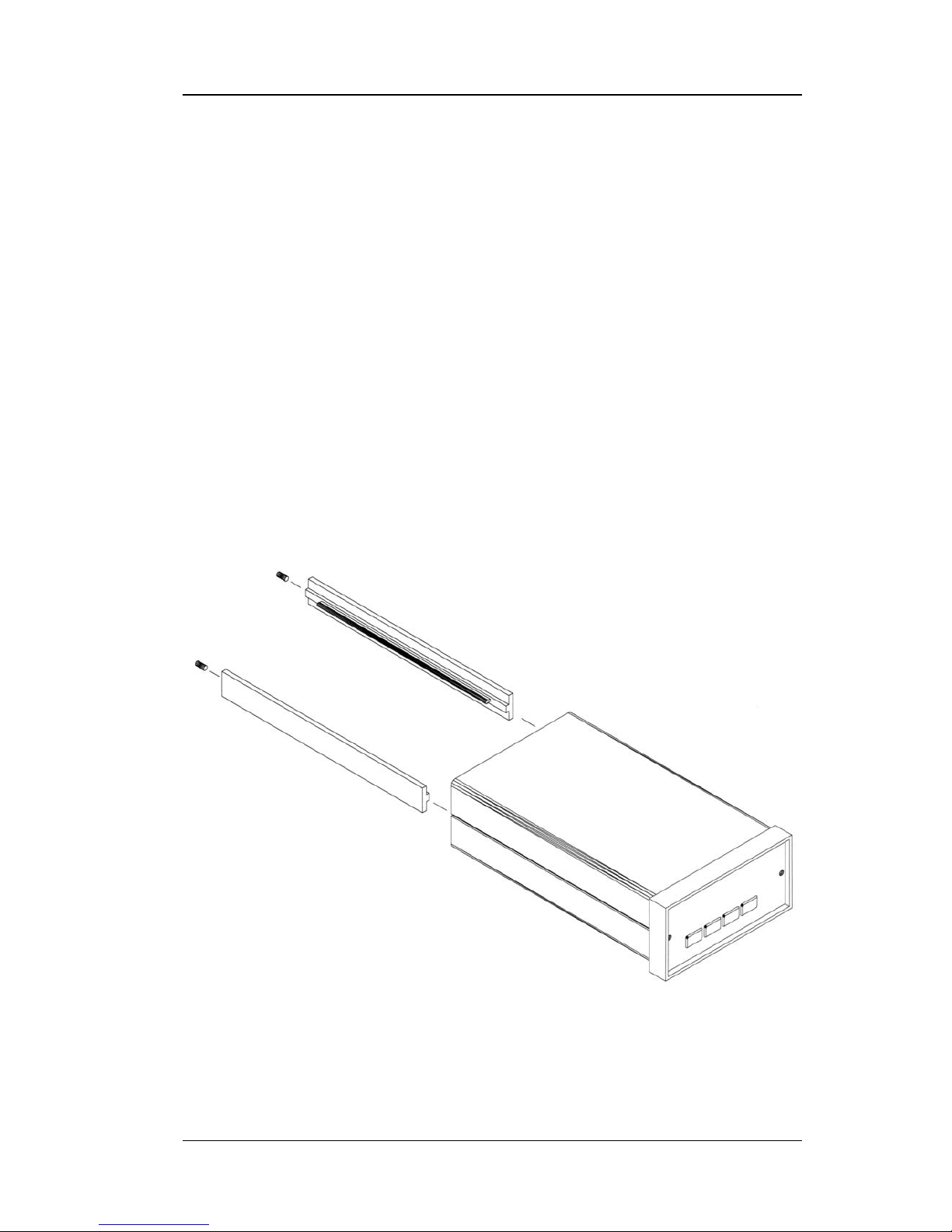
2.9 PANEL MOUNTING
The Model 211 can be easily panel mounted using the panel mount brackets
included. The Model 211 fits in a 91 × 44 mm (3.6 × 1.7 in) cutout. To
panel-mount the instrument, unplug the unit and use a
1
⁄
16
-inch hex wrench
to remove the two set screws holding the brackets in place. Remove the two
panel mount brackets by sliding them towards the rear of the unit. Place the
unit into the panel cutout. Slide the two panel mount brackets back into the
case of the instrument. Reinstall the two set screws and tighten them until
the instrument is secure.
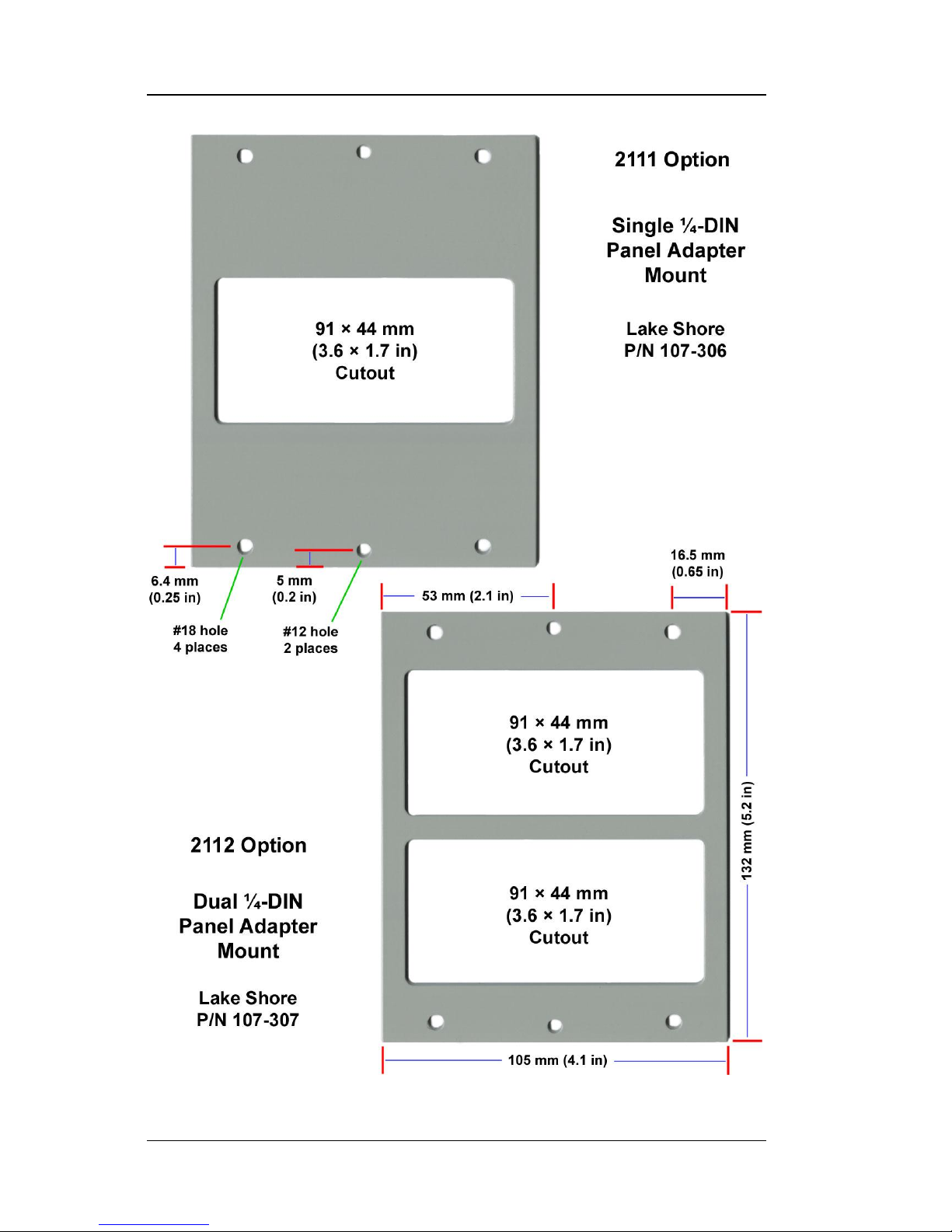
The Model 211 can also be purchased with either of two panel mount
adapters. The Model 2111 or 2112 will mount one or two temperature
monitors in a ¼-DIN cutout measuring 105 mm wide × 132 mm high
(4.1 × 5.2 in). See Figure 2-5.
Panel.bmp
Figure 2-4. Panel Mounting Details
Lake Shore Model 211 User’s Manual
2-10 Installation
Figure 2-5. 2111 and 2112 Panel Mount Adapters

Lake Shore Model 211 User’s Manual
Operation 3-1
CHAPTER 3
OPERATION
3.0 GENERAL
This chapter provides operating instructions for most features of the Model
211 Temperature Monitor. Corresponding computer interface instructions
for these features are provided in Chapter 4.
3.1 INSTRUMENT POWER
The Model 211 is powered on by plugging in the power supply. There is no
power switch on the instrument. When the Model 211 is powered on, every
segment on the display will illuminate for a few seconds to indicate
instrument initialization. Most of the instrument setup parameter values are
retained when powered off with one exception. The latching alarm will reset
itself on power-up. When the instrument is powered on for the first time,
parameter values are set to their defaults, listed in Table 3-6.
When initialization is complete, the instrument will begin its normal reading
cycle and temperature or sensor units readings should appear on the display.
Messages will appear in the reading location on the display if the
measurement input has not been fully configured. Messages listed in
Paragraph 5.3.1, Instrument Hardware Errors, are related to the instrument
hardware, and may require help from Lake Shore service. The messages
listed in Paragraph 5.3.2, Limit Errors, do not indicate a problem with the
instrument, and will disappear when input setup is complete.
The Model 211 should be allowed to warm up for a minimum of 30 minutes
to achieve rated accuracy.
3.2 DISPLAY DEFINITION
The Model 211 has a 6-digit LED display capable of showing both numeric
and character data. In normal operation, the display shows the current
sensor reading in sensor units or temperature units. The four annunciators
below the right hand side of the display indicate what units the display is
reading. Other display configurations appear during parameter setting and
data entry operations. These displays are illustrated in their individual
operation paragraphs.
 Loading...