

Page 1
Environmental Contamination
When performing routine maintenance, the system's fluid is commonly
exposed to environmental contamination. Exercise caution during
routine maintenance to prevent this type of contamination. Be sure to
change breather filter and systems air filter regularly.
Self-Generation Contamination
Self-generated contamination is a product of wear, cavitation, fluid
breakdown and corrosion. Systems that are carefully flushed,
maintained, and have fresh fluid added, mainly have self-generated
contamination. In this case, proper filtration can prevent fluid component
malfunction.
Lake Monitors 8809 Industrial Drive, Franksville, WI 53126
toll free: 800.850.6110 fax: 262.884.9810
www.lakemonitors.com
©2007 AW-Lake Company. All rights reserved. CVMAN-907 MWR
Rev. 05/24/12
Installation, Operating
& Maintenance Manual
Page 2
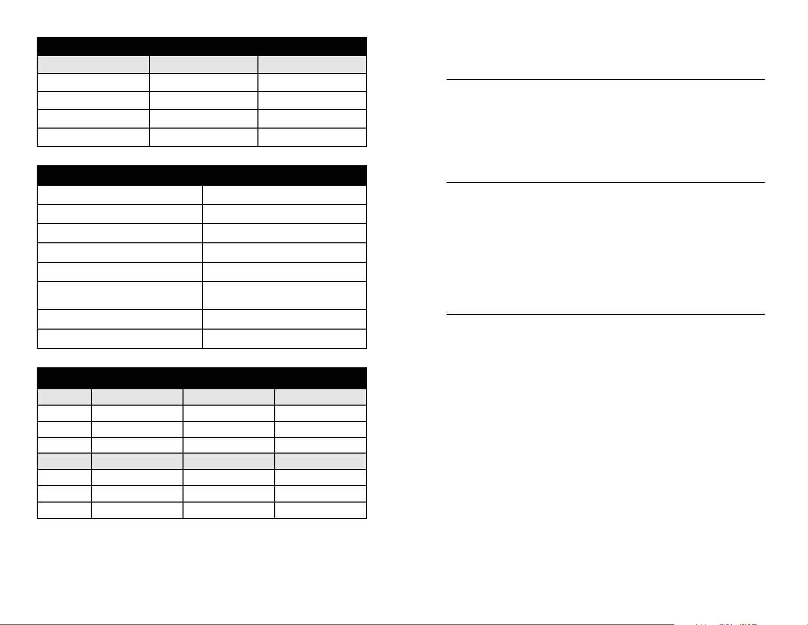
Materials of Construction (Wetted Components)
ClearView H2O
End Ports Brass Brass
Seals Buna-N Buna-N
Spring Stainless Steel Stainless Steel
Indicator and Casing Polycarbonate Polysulphone
ClearView +
CONTAMINATION AND FILTRATION
Recommended Filtration
The manufacturer recommends system filtration of at least 74 micron
filter or a 200 mesh screen. It has been found that if inadequate filtration
has caused meter failure, it will normally fail in the open position. Some
systems may require a magnetic filter. IMPORTANT: Meter damage
caused by excessive contamination is not covered under warranty.
Performance
Measuring accuracy: ±5% of full-scale
Repeatability: ±1% of full-scale
Flow Measuring Range: 1-30 GPM (5-110 LPM)
Turn Down Ratio (All Ranges:) 10:1
Maximum operating pressure: 325 PSIG (22.4 bar)
Maximum operating temperature:
Pressure Differential: See graph on right.
Filtration requirements: 74 Micron (200 U.S. mesh) min.
ClearView H2O: 200°F (93°C)
ClearView+: 250°F (121°C)
Mechanical Dimensions*
DIM ½" Male ¾" Male 1" Male
A 2-7/16" (62mm) 2-7/16" (62mm) 2-7/16" (62mm)
B 7-11/16" (195mm) 8-1/32" (204mm) 8-3/32" (206mm)
Port Size NPTF ½", SAE #8 NPTF ¾", SAE #12 NPTF 1", SAE #16
DIM ½" Female ¾" Female 1" Female
A 2-7/16" (62mm) 2-7/16" (62mm) 2-7/16" (62mm)
B 7-5/32" (182mm) 7-9/16" (192mm) 7-9/16" (192mm)
Port Size NPTF ½", SAE #8 NPTF ¾", SAE #12 NPTF 1", SAE #16
*Refer to Figure 1 at right.
Stabilized Contamination
The goal of filtration is to create effective protection from system
contamination. Proper filtration stabilizes contamination to allow fluid
components to function properly. A fluid system is considered
stabilized when, “contamination in” equals “contamination out”. Proper
filtration must reduce initial contamination to a stabilized level within
an acceptable time period. the system should be stabilized in time to
prevent premature wear or damage to meter components.
Contamination Sources
Fresh Fluid
When fresh fluid is stored in holding tanks, it may be contaminated
with scale or metal flakes from inside the tank. To prevent this type of
contamination, be sure to filter fresh fluid before adding to the system.
New Machinery Contamination
When building new machines, a certain amount of built-in
contamination is unavoidable. Typical built-in contamination consists
of dust, dirt, chips, fiber, and sand, flushing solutions, moisture, weld
splatters and pipe sealants. Flushing the system before operation can
reduce contamination, but cannot eliminate it totally.
Unless the system is flushed at a high velocity, some contamination
will not be dislodged until the system is in operation. System
contamination can cause fluid component malfunction.
(2)
(7)
Page 3
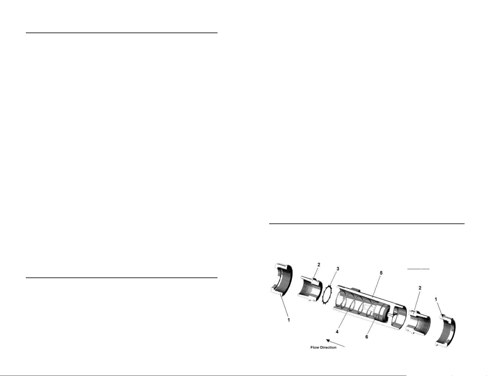
tubular, with all internal wetted parts sealed within the body casing
(5). Running through the center of the body casing is a tapered center
shaft which is centered in the bore. Encircling the shaft is a sharpedged, floating metering poppet (6). The metering poppet is held in
the “no flow” position by the biased return spring (4). As the flow
moves through the meter it creates a pressure differential across the
floating orifice disk, forcing the disk and transfer magnet against the
return spring. As flow increases, the pressure differential across the
metering poppet increases, forcing poppet to move along the tapered
center shaft. As flow decreases, the biased return spring forces the
poppet down the tapered center shaft, returning to the “no flow” position.
Reading the Meter
Notice the black reference line which runs 360° around the metering
poppet. This reference line moves under the scale in direct relation to
the movement of the poppet. When fluid is flowing, the flow rate
through the meter is read by lining up the black reference line with
the closest rate line on the flow scale.
Specific Gravity or Density Effect
Basic Application Information
The flow meter can be installed directly in the fluid line without flow
straighteners or special piping. The meter is used to measure the flow
rate of most liquids which do not contain particles greater than 74 micron.
1) The casing and union retainers are made of either Polycarbonate
or Polysulphone materials permitting use with a variety of media.
Use of mild detergent to clean the meter body is encouraged to
prevent damaging the label or associated components.
2) The meter may be mounted in the most convenient location, in any
orientation to allow easy access for reading and maintenance.
3) The ClearView™meter should NOT be mounted near hot pipes or
equipment which can cause damage to the pressure vessel.
4) The ClearView™meter should not be mounted in a manner such
that piping misalignment or other system components can exert
force or produce a bending moment on the pressure vessel.
5) To retain accuracy and repeatability internal moving parts are
closely toleranced and require filtration of at least 74 micron or a
200 mesh screen.
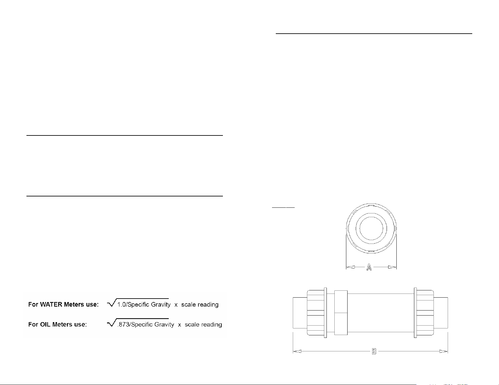
Standard meters are calibrated for either WATER with a specific gravity of
1.0 or OIL with a specific gravity of .873. The floating disk meter is
affected by fluid density as are most other similar type meters. Lake’s
meters have less of this effect because of the sharpness of the floating
orifice disks being used. The indicated flow reading will read high for
heavier fluids and low for lighter fluids. A corrective factor can be applied
to the standard scale or a special scale can be added at a slight
additional costs. When measuring fluids with other specific gravities, the
basic equations below can be used to develop corrected readings.
(6)
Figure 1:
Mechanical Dimensions
(3)
Page 4
Warning and Precautionary Areas
1) The meters are designed to operate in systems that flow in only
one direction: the direction of the arrow on the flow scale.
Attempting operation in the reverse direction may cause damage
to the meter or other system components.
2) The pressure vessel and its associated components are made of
Polycarbonate on the ClearViewH2O™meter. Polycarbonate can
be safely cleaned with soap and water. However, many other
cleaning agents can damage Polycarbonate, causing discoloration
or crazing. If you are unsure of your cleaning agent, call the
General Electric Polycarbonate Compatibility Reference Line at
800-845-0600.
3) When installing ClearView™meters onto threaded pipe caution
should be taken not to over tighten the pipe connections or intro
duce torque on the main body of the meter. The meter main body
may rupture if over-tightened.
4) The ClearView™meter should not be used in systems where the
assembled piping is not supported. Externally applied piping forces
may cause the meter to rupture or malfunction.
5) Operating Temperature: In standard meters, several components
have a maximum temperature rating (see specifications).
6) Operating Pressure: All meters are tested at a burst pressure three
times of operating pressure. Meters should not be used over the
operating pressure rating.
7) Thread seal tape: Caution should be used when using thread seal
tape on pipe thread joints. Leave at least 1/8" (3mm) of pipe
thread exposed from end of pipe when applying tape.
Basic Installation Information
ter in front of meter and in a location that allows easy access for routine maintenance. Refer to “Warnings and Precautionary Areas” for
additional information.
INSTALLATION DOS AND DON'TS
To obtain satisfactory operation from a Lake flow meter, the following
points should be considered:
DO:
n install a pressure gauge near the inlet of the meter
n place throttling valves at the outlet of the meter
n use pipe sealer on the connections
n install solenoid valves at meter outlet (as far downstream as possible)
n mount in any orientation: vertical, horizontal or upside down
DO NOT:
n place restrictions between the meter’s pressure gauge meter inlet
n use in systems where reverse flow is possible
n use pipe dope or thread seal paste on the connections
n place meter in non-aligned piping
n over-flow the meter by more than 150% of maximum reading
n operate at pressures and temperatures greater than specified
OPERATION
Operating Principles
Lake has developed a line of unique flow meters which combine the
simplicity of a sharp-edged orifice disk and a variable area flow meter.
See Figure 2 "Flow Meter Cross Section" below. The meters are
Figure 2:
Flow Meter Cross Section
The meters are mounted in-line and are direct reading. The meters
can be mounted in a vertical or horizontal position as long as the fluid
is flowing in the direction of the arrow on the flow scale. No straight
pipe is required before or after the meter. In fact, 90° elbows can be
installed on both ends without any noticeable flow variation. When
installing a meter, apply “Thread Seal Tape” on pipe threads, DO NOT
apply pipe dope or Thread seal paste. If tape is used, be sure to
leave 1/8" (3 mm) of pipe thread exposed on end of pipe. Position fil-
(4)
(5)
 Loading...