

Page 1

Ceiling mount
S24512BPX
Coverage area
SPECIFICATIONS
Model S24512BPX
Frequency, MHz 2400-2500 /5150-5850
Gain, dBi 3 dBi Typical for 2.4 GHz6
Elevation Plane Beamwidth 50° @ 2400-2500 MHz
20° @ 5150-5850 MHz
Azimuth Plane Beamwidth 360°
Wind Surface Area ft.
2 (m2
Wind Survivability, mph (kph) 125 (200)
Weight, lb. (kg) 0.30 (0.14)
Height, in. (cm) 9.6 (24.5)
Nominal Impedance, Ohms 50
VSWR 2.0:1 nominal
Power Handling, Watts 10
Radiating Element PC board
Enclosure Polycarbonate
Feed Reverse polarity SMA (male)
LAIRD TECHNOLOGIES, P.O. BOX 4680, MANCHESTER, NEW HAMPSHIRE
03108, WARRANTS TO THE ORIGINAL CONSUMER PURCHASER FOR TWO YEARS
FROM DATE OF PURCHASE THAT EACH LAIRD TECHNOLOGIES ANTENNA IS FREE OF
DEFECTS IN MATERIAL OR WORKMANSHIP. IF, IN THE JUDGMENT OF LAIRD,
ANY SUCH ANTENNA IS DEFECTIVE, THEN LAIRD TECHNOLOGIES WILL, AT
ITS OPTION, REPAIR OR REPLACE THE ANTENNA AT ITS EXPENSE WITHIN THIRTY
DAYS OF THE DATE THE ANTENNA IS RETURNED (AT PURCHASER'S EXPENSE) TO
LAIRD OR ONE OF ITS AUTHORIZED REPRESENTATIVES. THIS WARRANTY IS
IN LIEU OF ALL OTHER EXPRESSED WARRANTIES, ANY IMPLIED WARRANTY IS
LIMITED IN DURATION TO ONE YEAR. LAIRD TECHNOLOGIES SHALL NOT BE
LIABLE FOR ANY INCIDENTAL OR CONSEQUENTIAL DAMAGES WHICH MAY RESULT
FROM A DEFECT. SOME STATES DO NOT ALLOW LIMITATIONS ON HOW LONG AN
IMPLIED WARRANTY LASTS OR EXCLUSIONS OR LIMITATIONS OF INCIDENTAL OR
CONSEQUENTIAL DAMAGES, SO THE ABOVE LIMITATION AND EXCLUSION MAY NOT\
APPLY TO YOU. THIS WARRANTY GIVES YOU SPECIFIC LEGAL RIGHTS, AND YOU
MAY ALSO HAVE OTHER RIGHTS WHICH VARY FROM STATE TO STATE. THIS
WARRANTY DOES NOT EXTEND TO ANY PRODUCTS WHICH HAVE BEEN SUBJECT
TO MISUSE, NEGLECT, ACCIDENT OR IMPROPER INSTALLATION, ANY REPAIRS OR
ALTERATIONS OUTSIDE OF THE LAIRD TECHNOLOGIES FACTORY WILL NULLIFY
THIS WARRANTY.
SPECIFIC
LAIRD TECHNOLOGIES shall not be liable for any incidental or
consequential damages which may result from a defective, or use, or improper
email: sales@cushcraft.com - web: www.cushcraft.com
or otherwise or installation, improper or otherwise.
Please contact your vendor for technical support and warranty service
48 PERIMETER ROAD, MANCHESTER, NH 03103
Tel: 603-627-7877-Fax: 603-627-1764
LIMITED WARRANTY
ATIONS SUBJECT
Warranty and Liability
6 dBi Typical for 5.5 GHz
)0.07 (0.006)
36" (91.4 cm) Plenum
O CHANGE WITHOUT NOTICE
T
S24512BPX
2.4 and 5.5 GHz High Performance Antenna
Important Notice: Please read all instructions
carefully before attempting to install and use this
product.
SAFETY
The S24512BPX and all associated equipment should
be installed in accordance with applicable local and
national electrical code guidelines to ensure safe
operation.
LOCATION
For best results, mount the S24512BPX at ceiling or
roof level near the center of the coverage area. A lineof-sight path between the antenna and active floor
location generally works best. Although 2.4 GHz signals
penetrate cubical dividers and interior partitions with little
attenuation, reinforced block walls, banks of metal
cabinets, or steel shelving may attenuate signals or
cause multipath, a condition where reflected signals
interfere with the primary signal. Avoid mounting next
to a column or vertical support that could create a shadow
zone of reduced coverage to one portion of the room.
Each antenna comes with a ceiling-tile support-runner
mount and a U-bolt style pole mount.
APPLICATIONS
Laird Technologies' S24512BPX is a ruggedized
performance omnidirectional collinear antenna
highused for 2.4 and 5.5 GHz RF-distribution systems.
Its flattened radiation pattern focuses energy along
the horizontalplane to provide extended coverage
in
large rooms or vaulted areas (see Figure-1).
The S24512BPX may also be pole-mounted for
use in exterior locations.
164-00009_GF_AA
Page 2
MOUNTING
MOUNTING (cont.)
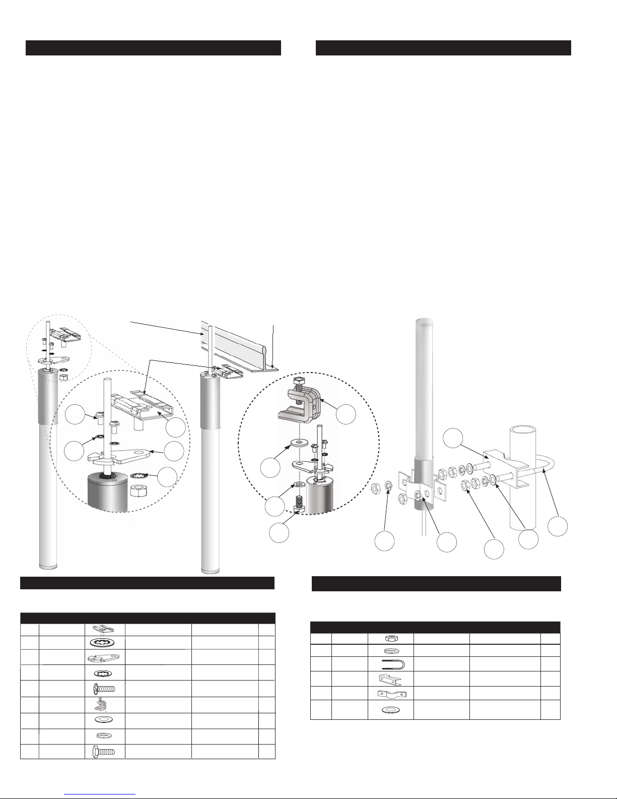
To install the antenna using the ceiling bracket:
1. Find the antenna bracket (77). Also, find two #6 phillips head screws (90)
and two #6 lock washers (89). Use the #6 hardware to secure the antenna
bracket to the antenna base (see Figure-1).
2. Find the tile runner bracket (HK). Remove the 1/4" - 20 hex nut and flat
washer from the bracket's carriage bolt in preparation for mounting.
Discard the flat washer-this will not be used.
3. Find the 1/4" lock washer (16). Insert the antenna bracket onto the
threaded end of the tile-bracket bolt (Figure-1). Install the 1/4"
lock washer and nut loosely-the halves of the tile bracket must slide
freely for final installation.
4. Clamp the ceiling bracket onto the support runner and tighten the 1/4"
mounting nut using a 7/16" wrench or adjustable wrench. Secure the
coaxial cable along the support runner using tape or cable ties.
5. If installing one antenna, attach the connector to the AP unit's Primary
antenna connection. If installing a diversity system, attach the leads
from the two antennas to the AP unit's Primary and Secondary jacks.
To install the antenna using the I-beam bracket:
1. For I-beam installations, first install bracket plate (77) as described
in Step-1.Next, referring to Figure-1A, install I-beam clamp (80) to the
bracket plate using flat washer (04), lock washer (84), and short 1/4"-20
bolt (55). Tighten the clamp bolt to secure antenna in place on beam.
FIGURE 1
Ceiling Support Runner
Loosened Bracket
Squeeze bracket onto
runner and tighten nut.
To install the antenna using the pole mount bracket:
1. Find the U-bolt (05), mast clamp (26), plus two 5/16" nuts (18) lock
washers (19) and (02) flat washers.
2. At the top of the pipe, using a 1/2" wrench or adjustable wrench, secure
the U-bolt to the clamp using the hardware provided (see Figure-2).
3. Find two more 5/16" nuts (18). Install these nuts by turning them down
against the nuts securing the U-bolt to the mast.
4. Find two antenna clamps (48), plus two 5/16" lock washers (19) and
the two remaining 5/16" nuts (18).
5. Sandwich the antenna between the two clamps at its base and slide
this assembly onto the U-bolt (Figure-2). Secure in place using
hardware provided.
6. Secure the coaxial cable along the mast or pole using tape or cable
ties.
7. If installing one antenna, attach the connector to the AP unit's Primary
antenna connection. If installing a diversity system, attach the leads
from the two antennas to the AP unit's Primary and Secondary jacks.
Note: for outside mounting or in wet environments,
make sure antenna is vertically mounted with weep holes
facing down.
FIGURE 2
FIGURE 1A
90
2 Places
89
2 Places
HK
77
04
16
Ceiling mount uses the
BPXCHK hardware kit
CONTENTS
BPXCHK (hardware kit for suspended ceiling mounting).
K EY P /N DIS PL AYDE SC S IZE QTY
HK S 2403B HH K GR ID BR AC KE T – 1
16 01021 6 INT . TOO TH 1/4” (00. 0 ) 1
77 19557 7 B R ACK E T 1
89 01558 9 INT. TOOTH 2
90 01559 0 S S MAC HINE #6-32 x 1 /4 ”
80 19498 0 I -BE AM CL AMP __ __ 1
04 01010 4 FL AT W AS HE R 1/4” 1
84 0 10084 S PL IT L OC K 1 /4 1
WA SH E R
55 015 655 HE X HE AD B O LT
L OC K W AS HE R
P LATE –
L OC K WASH E R #6
P HILL IPS SC R EW
1/4 X 20 X 1/2 1
2
84
55
Pole mount uses the
80
BPXPHK hardware kit
26
05
19
4 Places
48
2 Places
18
6 Places
02
2 Places
CONTENTS
BPXPHK (hardware kit for pole/mast mounting).
K E Y P /N DIS P LA Y DE S C SIZ E QT Y
18 010118 S S HE X NUT 5/16” x 18 (0 0.0) 6
19 010119 S S LO CK 5 /16” x (00 .0) 4
05 0104 05 U-B OLT –1
26 1957 26 V-B RA CK E T –1
48 1955 48 BA S E –2
02 0134 02 FL AT WAS HE R 5/16 2
WAS HE R
BR A CK E T
 Loading...