

Page 1
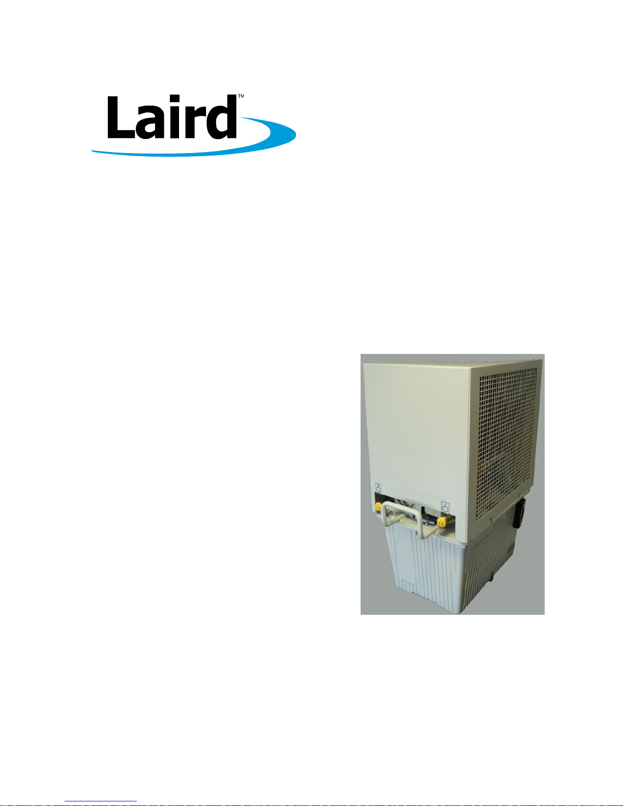
Operation Manual
Oil-Air Cooling Unit OL 4503
Version 2.0
Page 2

Laird Technologies GmbH
Borsigstrasse 1
D-24568 Kaltenkirchen
www.lairdtech.com
Protection Notice
Dissemination as well as copying of this document, utilization or posting of its contents is not permitted
unless formally granted. Violations entail claims for compensation. All copyrights, including rights due to
patent grant or registration of a utility model or design, are reserved.
All product names used in this manual are trademarks of the corresponding manufacturers.
Technical modifications subject to change.
Page 3

Table of Contents
3
Laird Technologies GmbH
Operation Manual (Translation)
Date: 06-Jul-2015
Version: 2.0
Oil-Air Cooling Unit OL 4503
1264.00
Table of Contents
1 About this Manual ............................................................................................................................ 6
1.1 Terms of Guarantee .............................................................................................................................6
1.2 Contact Information ..............................................................................................................................7
2 Product Identification ....................................................................................................................... 8
2.1 Unit Specifications ................................................................................................................................8
2.2 Identification Plate ................................................................................................................................8
3 Safety Regulations ........................................................................................................................... 9
3.1 Hazard classes ......................................................................................................................................9
3.2 Safety Symbols .....................................................................................................................................9
3.3 Hints for Safe Operation .................................................................................................................. 10
3.3.1 Prevent Hazards ..................................................................................................................................................... 10
3.3.2 Hints Regarding the Electrical Equipment .............................................................................................................. 10
3.3.3 Environmental Issues .............................................................................................................................................. 11
3.3.4 Protective Clothing .................................................................................................................................................. 11
3.4 Safety Equipment .............................................................................................................................. 11
3.4.1 Safety and Signalling Equipment included in the Unit ............................................................................................ 11
3.4.2 Guards ..................................................................................................................................................................... 12
3.4.3 Caution Label .......................................................................................................................................................... 13
3.5 In Case of Accidents ......................................................................................................................... 13
4 Product Description ....................................................................................................................... 14
4.1 Intended Use ...................................................................................................................................... 14
4.2 Non-Conformity with the Intended Use........................................................................................ 14
4.3 Unit Components ............................................................................................................................... 15
4.4 Specifications ...................................................................................................................................... 16
4.5 Setting-up Requirements ................................................................................................................. 17
4.5.1 Installation Location................................................................................................................................................. 17
4.5.2 Environmental Conditions ....................................................................................................................................... 17
4.5.3 Infrastructure ........................................................................................................................................................... 17
5 Transport .......................................................................................................................................... 18
5.1 Safety Indications for Transport and Setting-up ........................................................................ 18
5.2 Transportation of the unit ................................................................................................................. 18
5.3 Unpacking ............................................................................................................................................ 18
Page 4

Table of Contents
4
Laird Technologies GmbH
Operation Manual (Translation)
Date: 06-Jul-2015
Version: 2.0
Oil-Air Cooling Unit OL 4503
1264.00
6 Initial Operation ............................................................................................................................... 19
6.1 Safety Indications Related to Initial Operation ........................................................................... 19
6.2 Setting to Work ................................................................................................................................... 19
6.2.1 Placement ............................................................................................................................................................... 19
6.2.2 Cooling Circuit Connection and Filling .................................................................................................................... 20
6.2.3 Electrical Connections ............................................................................................................................................ 22
6.2.4 Carrying out Setting-to-Work .................................................................................................................................. 23
6.3 Daily Start-up ...................................................................................................................................... 23
6.4 Setting-to-Work after Storage ......................................................................................................... 23
7 Controlling the Unit ........................................................................................................................ 24
7.1 Safety Indications for Controlling the Unit ................................................................................... 24
7.2 Switching on the Unit ....................................................................................................................... 24
7.3 Switching off the Unit ....................................................................................................................... 24
7.4 Settings ................................................................................................................................................. 25
7.4.1 Pressure Setting on the Angle-type Safety Valve .................................................................................................. 25
7.4.2 Setting the Thermostat............................................................................................................................................ 26
8 Disruptions ....................................................................................................................................... 27
8.1 Disrupt Operation ............................................................................................................................... 27
8.1.1 Trouble Shooting ..................................................................................................................................................... 27
9 Maintenance and Cleaning ......................................................................................................... 28
9.1 Maintenance Schedule ................................................................................................................... 28
9.2 Cleaning of Heat Exchanger ........................................................................................................... 28
9.3 Refilling of Coolant ............................................................................................................................. 28
9.4 Cleaning of Unit Casing ................................................................................................................... 29
10 Repair ............................................................................................................................................... 29
11 Dismounting, Disposal, Storage ................................................................................................. 30
11.1 Temporary Placing out of Operation ............................................................................................. 30
11.2 Re-packaging the Unit ...................................................................................................................... 30
11.3 Storing the Unit ................................................................................................................................... 30
11.4 Disposal ................................................................................................................................................ 31
11.5 Disposal of Operating Materials ..................................................................................................... 31
11.6 Return of the Unit to LAIRD ............................................................................................................ 31
12 Wear Parts and Spare Parts ....................................................................................................... 32
Page 5

Table of Contents
5
Laird Technologies GmbH
Operation Manual (Translation)
Date: 06-Jul-2015
Version: 2.0
Oil-Air Cooling Unit OL 4503
1264.00
Addendum ............................................................................................................................................. 34
Performance chart ....................................................................................................................................... 34
Flow scheme ................................................................................................................................................. 35
Wiring diagram .............................................................................................................................................. 36
History of Changes
Date
Index
Reason for Change
Name
Page
29-Nov-13
1.0
First version
Edom/Pfeiffer
06-Jul-15
2.0
Spare part numbers changed
Dany/Bitenaite
p. 33
Page 6

About this Manual
Terms of Guarantee
6
Laird Technologies GmbH
Operation Manual (Translation)
Date: 06-Jul-2015
Version: 2.0
Oil-Air Cooling Unit OL 4503
1264.00
1 About this Manual
This document is the English translation of the original Operation Manual in German language for the Oil-Air
Cooling Unit OL 4503 (called unit in the following). It is based on German safety regulations. In your country
other regulations may apply.
This Operational Manual addresses the needs of the user of the unit. Its intention is to allow the safe
operation of the unit. Thus, it should be read carefully and be kept in a space accessable for the users of the
unit at any time.
All chapters of this Operation Manual can be read independently and thus can be used for look-up purposes.
1.1 Terms of Guarantee
General sale and delivery terms of LAIRD apply. The buyer accepts these terms, at the latest when signing
the contract of purchase.
The particular terms of guarantee and duration of guarantee of the unit in question can be taken from the
contract documents as well as from the order confirmation.
Warranty claims and liability are excluded in case of one of the following situations:
Use of the unit in an unintended way
Inaccurate installation, putting into service, operation, repair or maintenance of the product by people
that are not fully authorized
Use of the product despite of defect, wrongly implemented or non-functional safety devices or
protective gear
Unauthorized or forbidden modifications by the user concerning the electrical equipment of the unit
Unauthorized or forbidden modifications by the user concerning the mechanical structure of the unit
Unauthorized or forbidden modifications by the user concerning the operating parameters
Use of unauthorized tools
Use of unauthorized operating supplies
Exceedance of mandatory maintenance intervals
Cases of disaster caused by foreign matter influence or act of nature beyond control
PLEASE NOTE
Any form of unintended use of the unit and any structural change caused by the user without prior
authorization in written form by LAIRD will lead to the termination of warranty as well the termination of the
declaration of conformation and will free LAIRD from product liability. This concern includes safety devices
as well.
In case of authorized changes or when adding optional equipment it is the sole responsibility of the customer
to assure the accurate implementation of the safety devices required.
Page 7

About this Manual
Contact Information
7
Laird Technologies GmbH
Operation Manual (Translation)
Date: 06-Jul-2015
Version: 2.0
Oil-Air Cooling Unit OL 4503
1264.00
1.2 Contact Information
If you have questions with respect to this unit please use the contact information given below. Always
communicate the following:
Your name and address
Name of contact at your address
Product data as on identification plate: Type of unit, serial number and year of manufacture
Company contact:
Mail:
Laird Technologies GmbH
Borsigstrasse 1
D-24568 Kaltenkirchen
Deutschland
Internet:
http://www.lairdtech.com
E-Mail:
info-lcs@lairdtech.com
Phone:
+49 4191 9993-0
Fax:
+49 4191 9993-33
Page 8

Product Identification
Unit Specifications
8
Laird Technologies GmbH
Operation Manual (Translation)
Date: 06-Jul-2015
Version: 2.0
Oil-Air Cooling Unit OL 4503
1264.00
2 Product Identification
2.1 Unit Specifications
Manufacturer
Laird Technologies GmbH
Type of product
Oil-air cooler
Type of unit
OL 4503
Article number
1264.00
Table 1: Unit specifications
2.2 Identification Plate
The identification plate is attached on the top of the coolant container below the unit cover.
Fig. 1: Position of identification plate
1
Identification plate
Fig. 2: Unit specific identification plate
1
Unit type
2
Article number
3
Serial number
4
Electrical specification
5
Date of manufacture
1
1
2
4
3
5
Page 9

Safety Regulations
Hazard classes
9
Laird Technologies GmbH
Operation Manual (Translation)
Date: 06-Jul-2015
Version: 2.0
Oil-Air Cooling Unit OL 4503
1264.00
3 Safety Regulations
3.1 Hazard classes
In this document safety instructions are using standardized representation and symbols. Depending on the
probability of their incidence and the severeness of consequences three hazard classes are used.
DANGER
Reference to direct danger for humans.
Inobservance will lead to irreversible injuries or exitus.
CAUTION
Reference to noticeable danger for humans or possible damage to property.
Inobservance may lead to reversible injuries or to damage to property.
3.2 Safety Symbols
In this Operation Manual concrete safety instructions are given in order to point out unpreventable residual
risks when operating the unit. These risks include danger for
Human beings
The unit and other equipment
The environment
The safety symbols used in this manual are indicated below. The main reason for their use is to point the
reader to the safety instruction given in the text field beside.
Symbol
Meaning
Warning with respect to general danger or damage to property
Warning with respect to electrical hazard
Table 2: Warning signs
Symbol
Meaning
This symbol indicates the requirement of wearing safety gloves
This symbol indicates the requirement of disconnecting from mains.
Table 3: Signs giving orders
Page 10

Safety Regulations
Hints for Safe Operation
10
Laird Technologies GmbH
Operation Manual (Translation)
Date: 06-Jul-2015
Version: 2.0
Oil-Air Cooling Unit OL 4503
1264.00
3.3 Hints for Safe Operation
PLEASE NOTE
Conduct inspections on a regular time base
This will ensure that the appropriate measures will be carried out indeed.
The unit is operation save. It was built according to the state-of-the-art.
Despite this the unit could cause hazards if it
is used in a way it was not intended for
is used improperly
is operated under unsuitable conditions
3.3.1 Prevent Hazards
Hazards can be prevented by safety-conscious and anticipatory behaviour of staff.
Everybody working with the unit should keep the following in mind:
Make this Operation Manual available for everybody at the operation site of the unit in a complete and
perfectly readable state!
Use the unit exclusively for what it was intended!
The unit must be operational and errorfree. Check the condition of the unit before working with it and
within a regular time frame.
Make sure that nobody can injure himself by any part of the unit!
Any disruption or recognizable change concerning the unit should be reported to the responsible
person.
Stick to accident prevention regulations as well as any regional regulations!
3.3.2 Hints Regarding the Electrical Equipment
DANGER
Danger to life through electrical shock when working on the electrical equipment of the unit!
Switch off the unit before starting your work!
Disconnect the unit from mains by pulling the mains plug!
Verify that the installation is dead (volt-free)!
Carry out earthing or short circuiting!
When working on electrical installations the following principles should be observed:
Works on the electrical installations may only be accomplished by qualified electrical staff!
When connecting electrical equipment to mains regional regulations have to be observed. Be aware of
the wiring diagram information.
The unit is powered by electricity. Electrical shock hazard exists, if the electrical installations are
defective or the insulation fails during operation.
When switched-off the unit is not disconnected from mains. This is only the case when the mains plug
is pulled.
Any changes regarding the control elements of the unit can have an influence on the save operation.
All intended changes must be authorized by the manufacturer.
After the implementation of a change the operativeness of the safeguards must be verified.
Page 11

Safety Regulations
Safety Equipment
11
Laird Technologies GmbH
Operation Manual (Translation)
Date: 06-Jul-2015
Version: 2.0
Oil-Air Cooling Unit OL 4503
1264.00
No unauthorized changes on the unit are allowed. All intended changes must be authorized by the
manufacturer.
3.3.3 Environmental Issues
Environmentally concious and anticipatory behaviour of staff avoids environmentally hazardous impacts.
The following principles apply for environmentally conscious behaviour:
Environmentally hazardous substances must not get into the soil or into the drains. They should be
kept in appropriate containers.
Environmentally hazardous substances must be brought to utilization or disposal according to regional
regulations.
When dealing with working fluids always keep aware of the safety data sheet of the corresponding
manufacturer.
3.3.4 Protective Clothing
When doing a job that leads to contact of the skin with the coolant (e.g. filling-up of the coolant container):
Wear safety gloves made of PVC, neoprene or nitrile rubber
3.4 Safety Equipment
PLEASE NOTE
The safety equipment listed below must be integrated in the local control environment by the customer,
unless otherwise noted. These tasks must be carried out solely by trained experts. All information required
can be taken from the wiring diagram shown in the addendum.
Safety equipment must not be modified, removed or taken out of operation. All parts of the safety equipment
must be accessible at all times.
3.4.1 Safety and Signalling Equipment included in the Unit
The unit is equipped with safety equipment at critical spots:
The filling level of the coolant container is indicated in an inspection glass.
The circulated oil amount is controlled by a flow control device (flow switch) that must be integrated in
the potential-free safety circuit of the device that is to be cooled.
The oil temperature is controlled by a thermostat. When the oil temperature exceeds the maximum
setpoint this is indicated by the potential-free safety circuit.
The maximum pump pressure is limited by an angle-type safety valve that bypasses the oil stream
when the pressure pre-set is exceeded.
Page 12

Safety Regulations
Safety Equipment
12
Laird Technologies GmbH
Operation Manual (Translation)
Date: 06-Jul-2015
Version: 2.0
Oil-Air Cooling Unit OL 4503
1264.00
Fig. 3: Safety equipment
1
Thermostat
2
Flow control device (flow switch)
3
Angle-type safety valve
4
Inspection glass, level indicator
3.4.2 Guards
Direct access to hazardous parts or areas of the unit is restricted by the unit cover. The cover may only be
removed for the purpose of maintenance or repair works and shall be replaced prior to taking the unit back to
operation. The cover is fixed by four screws which can be unscrewed using a metric AF10 wrench.
Fig. 4: Guard
1
Unit cover
1
2
3
4
1
Page 13

Safety Regulations
In Case of Accidents
13
Laird Technologies GmbH
Operation Manual (Translation)
Date: 06-Jul-2015
Version: 2.0
Oil-Air Cooling Unit OL 4503
1264.00
3.4.3 Caution Label
Danger spots on the unit are indicated corresponding to German safety regulation BGV A8 "Sicherheits- und
Gesundheitsschutzkennzeichnung am Arbeitsplatz"
Caution labels on the unit must be easily readable at all times. Illegible caution labels must be exchanged
without delay.
Fig. 5: Caution labels on the unit
1
Hint for using the correct cap on oil filler
3.5 In Case of Accidents
Should you or an other person be injured when working with the unit:
Stay calm!
Give first aid!
Call the company’s first-aider without exception!
First aid at accidents with oil
The unit employs oil as a coolant in a closed-loop configuration. In case of damage oil can leak from the
circuit and cause hazards.
Long term or repeated contact with skin without appropriate cleaning may obstruct the skin pores and
may lead to irregularities as oil acne or folliculitis.
When exposed to oil always observe the safety data sheet of the manufacturer.
1
Page 14

Product Description
Intended Use
14
Laird Technologies GmbH
Operation Manual (Translation)
Date: 06-Jul-2015
Version: 2.0
Oil-Air Cooling Unit OL 4503
1264.00
4 Product Description
4.1 Intended Use
The oil-air cooler OL 4503 is used for the cooling of an oil circuit. Oil circulates between the cooling unit and
the device to be cooled. The oil is recooled by an air-cooled heat exchanger. The maximum cooling capacity
depends on the ambient air temperature (see page 16 ).
The unit is exclusively intended for use in industrial and commercial environments.
The intended use also includes the observance and following of all hints given in this Operation Manual.
4.2 Non-Conformity with the Intended Use
Operation of the unit under improper operational conditions is not permitted, since otherwise the operation
safety can not be granted.
When using the unit in a way not compliant with the intended use, hazardous situations may occur.
Operation of the unit is not permitted under the following conditions:
The unit is used for a purpose other than the one it is intended for.
The unit or parts of it are damaged, the electrical installation is not correct or the insulation is broken.
Protective or safety equipment is not functional or defect, improperly installed or missing.
The unit is not working properly.
The unit was modified without authorization or modified in a way that is not permitted.
Controlling devices were modified in a way that is not permitted.
Operational parameters were changed in a way that is not permitted.
Operation in areas exposed to explosion hazards.
Operation with cooling media not according to specification.
Use of unauthorized tools.
Exceedance of the compulsary maintenance intervals.
PLEASE NOTE
The manufacturer is not liable for damage occuring when using the unit in a way it was not intended.
When using the unit in a way it was not intended for, the manufactorer’s waranty given by LAIRD will
expire.
Page 15

Product Description
Unit Components
15
Laird Technologies GmbH
Operation Manual (Translation)
Date: 06-Jul-2015
Version: 2.0
Oil-Air Cooling Unit OL 4503
1264.00
4.3 Unit Components
Additional information can be retrieved from the flow scheme shown in the addendum. The unit consists of
the following main components:
Fig. 6: Main components
1
Cooling circuit
2
Coolant container
3
Sheet-metal hood
Cooling Circuit
In the cooling circuit the coolant (i.e. the oil) is driven by the pump to the device that is to be cooled and back
via the return flow. The heat is dissipated into the ambient air by an air-cooled heat exchanger. Exceedance
of the maximum pump pressure is prevented by a bypass circuit.The oil temperature is controlled by an
electronic thermostat. Oil throughput is controlled by a flow control device.
Fig. 7: Main components
1
Stop valve
2
Fan 3 Oil drain screw
2
1
3
1
3
2
Page 16

Product Description
Specifications
16
Laird Technologies GmbH
Operation Manual (Translation)
Date: 06-Jul-2015
Version: 2.0
Oil-Air Cooling Unit OL 4503
1264.00
4.4 Specifications
Dimensions and weight
Length:
650 mm
Width:
350 mm
Height:
750 mm
Weight:
49.6 kg (empty)
Coolant capacity:
23 liters (Shell Diala S3-ZXIG)
Table 4: Dimensions and weight
Performance data
Cooling capacity:
4500 Watts at 22.8 K difference between the
oil outlet temperature and the ambient air
temperature
Pump capacity:
> 22 lpm at 3.5 bar
Mains voltage:
230 VAC 10% 50/60 Hz
Power input:
785 Watts (P
max
; 230 V; 50 Hz)
1058 Watts (P
max
; 230 V; 60 Hz)
Table 5: Performance data
Environmental conditions
Operating temperature:
-10°C ... +40°C
Storage temperature:
-25°C ... +70°C
Relative humidity:
20% … 90%
Table 6: Environmental conditions
Settings
Flow control device
14.0 ± 0.3 lpm
Thermostat
55 ± 3 °C
Maximum pressure
9.0 +0.5/-0.2 bar
Table 7: Settings
Page 17

Product Description
Setting-up Requirements
17
Laird Technologies GmbH
Operation Manual (Translation)
Date: 06-Jul-2015
Version: 2.0
Oil-Air Cooling Unit OL 4503
1264.00
4.5 Setting-up Requirements
4.5.1 Installation Location
The location must be even.
When choosing the installation location the following must be kept in mind: the flow of the cooling air
must not be restricted, forward and back flow connections must be easily accessable and all hoses
must be installed without sharp bends.
4.5.2 Environmental Conditions
CAUTION
Risk of damage through unsuitable environmental conditions!
Damage to the unit and corrosion damage may result and are not covered by manufacturer’s
liability.
The unit is only authorized for use in indoor environments.
The unit must not be stored or operated in agressive, humid environments.
The unit must not be stored or operated outdoor.
Pay attention to the environmental conditions as given in the specifications on page 16.
4.5.3 Infrastructure
The following infrastructure is required for connecting the unit:
Parameter
Rated value
Operating voltage
230 VAC
Table 8: Required infrastructure
Page 18

Transport
Safety Indications for Transport and Setting-up
18
Laird Technologies GmbH
Operation Manual (Translation)
Date: 06-Jul-2015
Version: 2.0
Oil-Air Cooling Unit OL 4503
1264.00
5 Transport
5.1 Safety Indications for Transport and Setting-up
CAUTION
Risk of injury by lifting the unit!
The weight of the unit is more than 50 kg.
Do not lift the unit manually.
Always use proper auxiliary means such as a forklift or a jack lift.
CAUTION
Risk of damage by improper transportation!
Transport the unit in upright position.
Do not tilt the unit or expose it to impacts.
5.2 Transportation of the unit
The unit is delivered shrinked in foil on a transportable pallet. Leave the unit on the pallet until bringing it into
service. Use a forklift or jacklift for transportation to the installation location.
5.3 Unpacking
Remove the foil before setting up the unit.
Inspect the unit with regard to:
Damage caused by transportation
Completeness of delivery
Lift the unit with a forklift or jack lift off the transportable pallet.
Dispose of the packaging material in accordance with regional regulations
PLEASE NOTE
LAIRD advises to keep the transportable pallet for later transportation of the unit.
Page 19

Initial Operation
Safety Indications Related to Initial Operation
19
Laird Technologies GmbH
Operation Manual (Translation)
Date: 06-Jul-2015
Version: 2.0
Oil-Air Cooling Unit OL 4503
1264.00
6 Initial Operation
6.1 Safety Indications Related to Initial Operation
CAUTION
Danger of malfunction caused by faulty connections during initial operation!
Before switching on the unit make sure that:
All safety equipment of the unit is implemented and functional.
All connections were properly made.
Nobody is endangered by the start-up of the unit.
Please follow the rules in chapter Safety Regulations on page 9.
6.2 Setting to Work
6.2.1 Placement
Fig. 8: Minimum clearance for air entrance and air exit
1
Ventilation grid
1) Move the unit to its installation location as mentioned in chapter 5.2
2) Place the unit in a way that air entrance and air exit are not obstructed. Wall clearance must not be less
than 0.5 m, otherwise cooling capacity may be restricted
PLEASE NOTE
In case of storage of the unit at temperatures lower than 5°C or higher than 40°C for longer periods please
wait 3 hours prior to initial operation to allow for temperature adjustment.
1
min. 0.5 m
min. 0.5 m
1
Page 20

Initial Operation
Setting to Work
20
Laird Technologies GmbH
Operation Manual (Translation)
Date: 06-Jul-2015
Version: 2.0
Oil-Air Cooling Unit OL 4503
1264.00
6.2.2 Cooling Circuit Connection and Filling
CAUTION
Risk of damage by using improper cooling hoses!
This may lead to damage to persons, damage to the unit or corrosion damage.
When choosing cooling hoses pay attention to sufficient burst strength and compatibility with coolant.
Only use cooling hoses without any signs of damage.
The cooling hoses are connected to the unit by means of screwed hose nipples.
Oil inlet and oil outlet are indicated with respective symbols.
Fig. 9: Labelling of oil inlet and oil outlet
PLEASE NOTE
When operating the unit make sure only to use the operation coolant container cap. This cap allows for
pressure equilibrium in the cooling system (breathing). Save the transportation cap for later transportation
purposes (e.g. when sending the unit back for repair).
Oil Inlet
Oil Outlet
Page 21

Initial Operation
Setting to Work
21
Laird Technologies GmbH
Operation Manual (Translation)
Date: 06-Jul-2015
Version: 2.0
Oil-Air Cooling Unit OL 4503
1264.00
Fig. 10: Operation cap, transportation cap, filler plug of coolant container
1
Operation cap
2
Transportation cap
3
Filler plug of coolant container
1) Unscrew the four screws of the unit cover using a metric AF10 wrench and remove the cover.
2) Remove the caps from the hose nipples of oil inlet and oil outlet.
3) Connect a hose to the hose nipples for oil inlet and oil outlet and secure it with a hose clamp,
respectively.
4) Connect the hoses to the corresponding nipples of the device to be cooled.
PLEASE NOTE
When connecting the cooling hoses pay attention to flow direction. Follow the documentation released by
the manufacturer of the device to be cooled.
5) Remove the transportation cap on the coolant container using an appropriate wrench.
6) Fill the coolant container with oil up to a filling level indicated roughly in the center of the inspection glass.
Use a funnel in order not to moisten any current-carrying components with oil
7) Close the coolant container using the operation cap supplied on delivery.
1
2
3
Page 22

Initial Operation
Setting to Work
22
Laird Technologies GmbH
Operation Manual (Translation)
Date: 06-Jul-2015
Version: 2.0
Oil-Air Cooling Unit OL 4503
1264.00
6.2.3 Electrical Connections
DANGER
Danger to life by electrical shock when working on the electrical equipment of the unit!
Switch off the unit before starting your work!
Disconnect the unit from mains by pulling the mains plug!
Verify that the installation is dead (volt-free)!
Carry out earthing or short-circuiting!
CAUTION
Risk of damage through improper connections!
Improper integration of the unit into the safety circuit of the device to be cooled will lead to the
inoperativeness of the safety equipment listed in chapter 3.4.
All required connections must be incorporated according to the wiring diagram shown in the addendum.
Ensure that all connected safety equipment is properly functioning!
All tasks should be carried out only by expert staff.
PLEASE NOTE
The unit is delivered without a mains cable. The electrical connection as well as the integration into the
safety circuit of the device to be cooled are the customer’s responsibility and must be accomplished by
expert staff.
Information required can be taken from the specifications listed on page 16 and the wiring diagram
available in the addendum.
After implementing the mains cable connect the unit to mains by inserting the mains plug.
Page 23

Initial Operation
Daily Start-up
23
Laird Technologies GmbH
Operation Manual (Translation)
Date: 06-Jul-2015
Version: 2.0
Oil-Air Cooling Unit OL 4503
1264.00
6.2.4 Carrying out Setting-to-Work
CAUTION
Lack of coolant may destroy the pump!
Operate the unit only when the filling level of the coolant container is correct!
Check the filling level of the coolant container regularly!
After connecting the cooling circuit, filling the coolant container and finishing the electrical connection follow
the steps below for the setting-to-work of the unit:
1) Open the stop valve.
2) Let the unit run for about 1 minute in order to de-aerate the pump.
3) Switch off the unit.
4) Close the stop valve.
5) Let the unit run for about 10 minutes in order to fill and de-aerate the cooling circuit.
6) Switch off the unit.
7) Check the filling level using the inspection glass. Fill up oil, if required, until a liquid level in the center of
the inspection glass. Use a funnel in order not to moisten any current-carrying components with oil.
8) Remount the unit cover.
DANGER
Danger to life by electrical shock caused by improperly mounted grounding washer!
Mount the grounding washer at the position of one of the four screws securing the unit cover!
Make sure that the screws are properly tightened!
This is to make sure that the grounding washer cannot get loose by vibrations during operation which could
lead to the situation of the unit cover carrying current.
9) Switch on the unit again and check the compliance with the operational parameters.
The unit is ready for use.
6.3 Daily Start-up
Switch on the unit about 1 minute prior to using the equipment that is to be cooled.
6.4 Setting-to-Work after Storage
Setting-to-work after storage will have to follow the same procedures as required for initial operation (see
chapter 6.2).
Page 24

Controlling the Unit
Safety Indications for Controlling the Unit
24
Laird Technologies GmbH
Operation Manual (Translation)
Date: 06-Jul-2015
Version: 2.0
Oil-Air Cooling Unit OL 4503
1264.00
7 Controlling the Unit
The unit is controlled by using the controls of the equipment that is to be cooled.
All alarm and error signalling is only indicated on the control panel of the equipment that is to be cooled.
7.1 Safety Indications for Controlling the Unit
CAUTION
Lack of coolant may destroy the pump!
Operate the unit only when the oil filling indication on the coolant container is correct!
Check the oil filling indication regularly!
Also pay attention to the hints given in the chapter Safety indications on page 9.
7.2 Switching on the Unit
The unit is ready for switching on.
1) Switch on the unit about 1 minute prior to operation of the device to be cooled using the appropriate
control of that device.
2) Check the compliance with the required operational data according to the specifications listed on page
16.
The unit is running.
7.3 Switching off the Unit
1) Switch off the unit using the control of the device to be cooled.
2) Close all valves that may exist along the hoses running to and from the unit
The unit is out of operation.
Page 25

Controlling the Unit
Settings
25
Laird Technologies GmbH
Operation Manual (Translation)
Date: 06-Jul-2015
Version: 2.0
Oil-Air Cooling Unit OL 4503
1264.00
7.4 Settings
The angle-type safety valve and the thermostat are set to the specified values by the manufacturer. Should
any modification be required, please follow the steps indicated below.
Fig. 11: Angle-type safety valve
1
Cover nut
2
Counter nut
3
Adjusting screw
4
Wrench to be used here for fixation
7.4.1 Pressure Setting on the Angle-type Safety Valve
PLEASE NOTE
A small amount of oil may leak from the valve.
The unit is switched off.
1) Loosen cover nut using a metric AF36 wrench and dismount. Use second wrench of the same size at
point 4 in Fig. 10 for holding the valve in place.
2) Loosen counter nut by turning it anticlockwise (use a AF36 wrench).
3) Set adjusting screw to the pressure value required:
Screwing in will increase the pressure setpoint.
Screwing out will decrease the pressure setpoint.
4) Tighten counter nut by turning it clockwise.
5) Re-install cover nut and tighten.
Pressure setting is accomplished.
6) Operate unit and check pressure.
If the intended pressure value is not yet reached, repeat the whole procedure.
1
2 3 2
4
Page 26

Controlling the Unit
Settings
26
Laird Technologies GmbH
Operation Manual (Translation)
Date: 06-Jul-2015
Version: 2.0
Oil-Air Cooling Unit OL 4503
1264.00
7.4.2 Setting the Thermostat
Fig. 12: Thermostat
1
Knob of thermostat
Increase the temperature setpoint
1) Turn the knob clockwise.
The switch-off temperature is set to a higher value.
Decrease the temperature setpoint
1) Turn the knob counter-clockwise.
The switch-off temperature is set to a lower value.
1
Page 27

Disruptions
Disrupt Operation
27
Laird Technologies GmbH
Operation Manual (Translation)
Date: 06-Jul-2015
Version: 2.0
Oil-Air Cooling Unit OL 4503
1264.00
8 Disruptions
8.1 Disrupt Operation
The most common reason for disrupt operation of the unit is improper maintenance. Maintenance should be
carried out regularly according to the maintenance intervals defined in chapter 9.
In case of disruption start with checking the follwing:
fan polluted or blocked?
coolant polluted?
Low coolant contents because of leakage, evaporation or an extended cooling circuit with long hoses?
More help can be found in the following paragraph.
In case you do not succeed in identifying the problem cause by means of this manual please contact the
service department of LAIRD.
8.1.1 Trouble Shooting
For trouble shooting you may rely on the follwing:
Alarm and error signalling within the safety circuit of the device to be cooled
Wiring diagram
Flow scheme
Trouble shooting table (see below)
Problem
Possible reason
Countermeasure
The unit does not start
Mains cable
plugged in?
Insert mains plug→ page 22
The unit is running, but
cooling capacity is not
available or too low
External hoses
sharply bent?
Pay attention to smooth bends when hoses are
connected
Unit properly
located?
Clearance to walls not less than 0.5 m → page 19
Coolant hoses
connected?
Connect hoses considering flow direction→ page 20
Is there flow in
cooling circuit?
Flow is signalled potential-free by the safety
equipment of the unit and can be visualized in the
range of controls of the device to be cooled.
Fan turning?
Cover the ventilation grid next to the fan with a sheet
of paper. If the paper is sucked and hold by the air
flow, the fan works properly
Ambient
temperature too
high?
Check specifications →page 16
Noisy unit
Contents in coolant
container low.
Refill coolant
Table 9: Trouble shooting list
Page 28

Maintenance and Cleaning
Maintenance Schedule
28
Laird Technologies GmbH
Operation Manual (Translation)
Date: 06-Jul-2015
Version: 2.0
Oil-Air Cooling Unit OL 4503
1264.00
9 Maintenance and Cleaning
Diligent maintenance is the prime factor for assuring an error-free and efficient operation of the unit.
Operating personnel can perform these tasks when properly trained.
9.1 Maintenance Schedule
Device
Activityt
Interval
Criteria
Tools
Performer
Heat Exchanger
Clean
Minimum weekly
(if required, daily)
Plate fins and
ventilation grids
not polluted
AF10 wrench,
compressed-air,
vaccum cleaner
Operating
personnel
Coolant container
Check filling
Weekly
Coolant indication
in the center of
inspection glass
Funnel, measuring
cup
Operating
personnel
Coolant quality
Inspect
visually
Weekly
Absence of
cloudiness or
floating particles
Inspection glass
on coolant
container
Operating
personnel
Table 10: Maintenance schedule
9.2 Cleaning of Heat Exchanger
Cooling capacity is reduced to a large extend, if the heat exchanger is polluted. The heat exchanger must be
checked for pollution regularly and be cleaned, if required.
For cleaning the heat exchanger follow these steps:
1) Switch off the unit.
2) Unscrew the four screws holding the unit cover with a AF10 wrench and remove the cover.
3) Clean the heat exchanger using compressed air opposite to the direction of air entrance into the unit
(i.e. from the inside out).
4) Remove any pollution from the ventilation grids using a vacuum cleaner.
5) Remount the unit cover.
The unit is ready for operation.
9.3 Refilling of Coolant
Since the cooling circuit is an open circuit, evaporation of coolant may occur. Thus the filling level of the
coolant container has to be checked regularly, and coolant might have to be refilled as described in chapter
6.2.2 on page 20.
Page 29

Repair
Cleaning of Unit Casing
29
Laird Technologies GmbH
Operation Manual (Translation)
Date: 06-Jul-2015
Version: 2.0
Oil-Air Cooling Unit OL 4503
1264.00
9.4 Cleaning of Unit Casing
CAUTION
Risk of damage due to the use of improper cleansing material!
When using aggressive or abrasive cleaning agents corrosion may occur as result of a damaged
paint film.
For cleaning the device casing only use mild cleaning agents (e.g.dish washing detergents)!
Use clean and lintless cloth for cleaning!
Regularly remove dirt from the casing of the unit to prevent corrosion damage and clogging of the air grids.
Pay attention that all the labels at the unit are always clean and legible.
10 Repair
PLEASE NOTE
Do not carry out any repair work on the unit. Send the unit back to the LAIRD service department (for
contact see page 7).
Page 30

Dismounting, Disposal, Storage
Temporary Placing out of Operation
30
Laird Technologies GmbH
Operation Manual (Translation)
Date: 06-Jul-2015
Version: 2.0
Oil-Air Cooling Unit OL 4503
1264.00
11 Dismounting, Disposal, Storage
11.1 Temporary Placing out of Operation
For placing the unit out of operation for maintenance or repair follow the steps below:
1) Switch off the unit.
2) Close all valves that may be incorporated in the cooling circuit.
3) Disconnect all hoses to and from the unit.
4) Place a collection container of sufficent volume (23 liters minimum) close to the drain screw.
5) Loosen the drain screw with a 10 mm Allen key and remove it.
6) Let the coolant container run empty into the collection container. To empty the coolant container
completely the unit must be tilted.
PLEASE NOTE
The coolant has to be collected and disposed of according to applicable regulations.
7) Re-attach the drain screw and clean the unit.
The unit is placed out of operation.
11.2 Re-packaging the Unit
In order to prevent spilling of residual coolant from the coolant container during transport the transport cap
must be attached.
The unit has been switched off, emptied (see chaper 11.1) and the unit cover has been
removed.
1) Remove the operation cap from the coolant container.
2) Attach the transport cap.
3) Remount the unit cover.
4) Put the protection caps on the hose clamps.
5) Lift the unit with a forklift or jacklift and place the transportable pallet under it.
6) Enclose the unit including the transportable pallet with shrinking foil and shrink the foil tight.
The unit is ready for transportation.
11.3 Storing the Unit
The storage area must be even and the unit should not stand on an edge or other obstructive object.
The environmental conditions for storage of the unit or parts of it can be found in the specification paragraph
on page 16.
Page 31

Dismounting, Disposal, Storage
Disposal
31
Laird Technologies GmbH
Operation Manual (Translation)
Date: 06-Jul-2015
Version: 2.0
Oil-Air Cooling Unit OL 4503
1264.00
11.4 Disposal
The unit was manufactured mainly from recycable material.
Make sure the components of the unit end up at a qualified company for disposal and recycling.
Contact LAIRD for take back of end-of-life units (see company contact on page 7) or ask a company
destined for disposal and recycling.
11.5 Disposal of Operating Materials
The operating materials of the unit can be hazardous to the environment and to health.
Make sure the operating materials are disposed of or recycled according to local regulations.
Also, the safety specifications of the coolant manufacturer must be obeyed.
11.6 Return of the Unit to LAIRD
PLEASE NOTE
Declaration of decontamination
Before re-shipment of the unit a declaration of decontamination must be sent to LAIRD.
Page 32

Wear Parts and Spare Parts
Return of the Unit to LAIRD
32
Laird Technologies GmbH
Operation Manual (Translation)
Date: 06-Jul-2015
Version: 2.0
Oil-Air Cooling Unit OL 4503
1264.00
12 Wear Parts and Spare Parts
Spare parts must comply with the technical specifications defined by LAIRD. Original LAIRD parts are
subject to strict obligations and fulfill these requirements.
LAIRD does not provide warranty service in case of damages caused by the use of spare parts made by
manufacturers other than LAIRD.
PLEASE NOTE
Identification data concerning the unit and spare parts
The type of unit and the article number can be found on the identification plate of the unit. The
corresponding numbers shown in drawings 12 and 13 as well as the part description are listed in the spare
part list (table 11).
Please direct your inquiries and orders to LAIRD (contact see page 7) with the following detailed information:
Type of unit
Article number
Serial number
Part description
Quantity
Shipping details
Fig. 13: Spare part overview part 1
3
10
9
7
6
2
8
1
Page 33

Wear Parts and Spare Parts
Return of the Unit to LAIRD
33
Laird Technologies GmbH
Operation Manual (Translation)
Date: 06-Jul-2015
Version: 2.0
Oil-Air Cooling Unit OL 4503
1264.00
Fig. 14: Spare part overview part 2
Pos.
Qty
Description
Article No.
1 1 Motor pump unit KA1-26-230-2
95205237.00
2 1 Thermostat AMFS-13
95160001.00
3 1 Axial fan S4E 330-AP 18-31
95251655.00
4 1 Starter capacitor for fan
95290709.00
5 1 Starter capacitor for pump
95290735.00
6 1 Stop valve ¼“
96521001.00
7 1 Angle-type safety valve
96121014.00
8 1 Inspection glass
93300201.00
9 1 Flow switch
95140572.00
10 1 Control head for flow switch
95140567.00
Table 11: Spare parts
4
5
Page 34

Addendum
Performance chart
34
Laird Technologies GmbH
Operation Manual (Translation)
Date: 06-Jul-2015
Version: 2.0
Oil-Air Cooling Unit OL 4503
1264.00
Addendum
Performance chart
Cooling capacity versus difference between entering air and supplied coolant temperatures
Leistungsdiagramm OL 4503
10
15
20
25
30
2,5 3 3,5 4 4,5 5 5,5 6 6,5
Leistung (KW)
D
t Temp. Lufteintritt / Öl-Vorlauf (°C)
Page 35

Addendum
Flow scheme
35
Laird Technologies GmbH
Operation Manual (Translation)
Date: 06-Jul-2015
Version: 2.0
Oil-Air Cooling Unit OL 4503
1264.00
Flow scheme
Page 36

Addendum
Wiring diagram
36
Laird Technologies GmbH
Operation Manual (Translation)
Date: 06-Jul-2015
Version: 2.0
Oil-Air Cooling Unit OL 4503
1264.00
Wiring diagram
 Loading...